

40.020.959 - rev. 01-2007
BX 3 / 9 / 15
GEBRUIKERSHANDLEIDING
USER MANUAL
BEDIENUNGSANLEITUNG
MANUEL DE L'UTILISATEUR
MANUAL DEL USUARIO
инструкция пользователя
motralec
4 rue Lavoisier . ZA Lavoisier . 95223 HERBLAY CEDEX
Tel. : 01.39.97.65.10 / Fax. : 01.39.97.68.48
Demande de prix / e-mail : service-commercial@motralec.com
www.motralec.com

/i
A
THERMOBILE
B
C
D
E
F
G
H
I
MODEL
VOLTS
INPUT
CURRENT
FREQUENCY
PROTECTION
PROD. NR:
Fabr.year 2006
THERMOBILE Ind. B.V. Breda, Holland
- 1 - - 2 -
1
2
3
- 3 - - 4 -
BX 3
230 V 3~
3 kW
13,2 A
50 Hz
IP X4
40.107.092
Serial nr: 49.0039
4
A
5
6
A
B
A
- 5 -
2 40.020.959 - rev. 01 - 2007 BX3 / BX9 / BX15
C
D
B
E
A
F
D
D
- 6 -
/i
G
BX3 / BX9 / BX15 40.020.959 - rev. 01 - 2007 3

Nederlands................................... 5
English .......................................12
Deutsch ......................................19
Français......................................26
Español ......................................34
Русский язык ............................ 42
4 40.020.959 - rev. 01 - 2007 BX3 / BX9 / BX15
Nederlands
All
Nederlands
Inhoud
Veiligheidsinstructies................................... 6
Introductie ................................................... 7
Voorbereidingen.......................................... 7
Gebruik ....................................................... 8
Onderhoud .................................................. 9
Storingen..................................................... 9
Reserveonderdelen................................... 10
Technische informatie ............................... 10
EG-Verklaring van overeenstemming ........11
Voorwoord
Deze handleiding bevat de
gebruiksaanwijzing voor de op de kaft
vermelde kachel. De informatie in deze
handleiding is belangrijk voor een juist en
veilig gebruik van de kachel.
Identificatie van het product (fig. 1)
Het identificatieplaatje is bevestigd op de
zijkant van de kachel. Het identificatieplaatje
bevat de volgende gegevens:
A Model
B Voltage
C Input
D Stroom
E Frequentie
F Beschermingsgraad tegen stof en vocht
G Productiecode
H Jaar van fabricage
I Serienummer
Milieu
Let op
De kachel is gemaakt van diverse
metalen en kunststoffen. De kachel
bevat tevens elektronische
onderdelen, die als elektronisch afval
moeten worden behandeld. Neem
contact op met uw dealer voor
nadere informatie.
een van toepassing in de
Europese Unie
Afvalverwijdering van elektrische
& elektronische apparatuur voor
zakelijk gebruik.
Voor nadere informatie aangaande
het wegwerpen van producten voor
zakelijke doeleinden aan het einde
van hun levensduur, wordt u verzocht
contact op te nemen met uw dealer
of distributeur in uw land. Dit product
mag niet samen met of in de vorm
van commercieel afval worden
weggegooid.
Service en technische ondersteuning
Neem voor informatie over de kachel contact
op met uw dealer of met de fabrikant.
Zorg dat u de volgende gegevens bij de hand
hebt: type en serienummer van de kachel.
Garantie en aansprakelijkheid
Voor garantie en aansprakelijkheid, zie de
algemene garantiebepalingen.
BX3 / BX9 / BX15 40.020.959 - rev. 01 - 2007 5
Nederlands
1 VEILIGHEIDSINSTRUCTIES
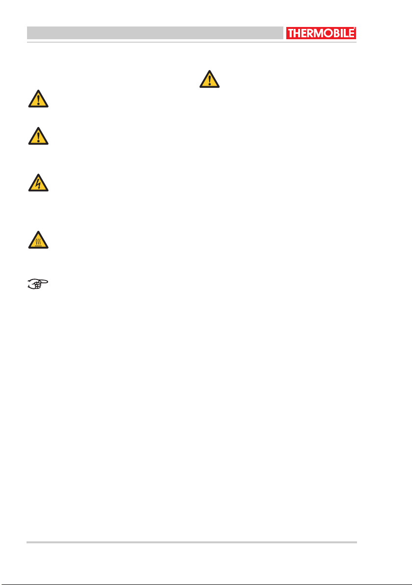
1.1 Pictogrammen in deze handleiding VOORZICHTIG
Wijst op gevaar voor beschadiging
van de apparatuur.
WAARSCHUWING
Wijst op een gevaarlijke situatie, die
de dood of ernstige verwondingen tot
gevolg kan hebben.
WAARSCHUWING
Schakel bij onderhouds- of
reparatiewerkzaamheden aan de
heteluchtkachel altijd de elektrische
stroom uit!
Heet
Sommige vlakken kunnen heet zijn!
Wacht met onderhoud totdat deze
onderdelen voldoende zijn afgekoeld.
Suggesties en tips om de uitvoering
van de betreffende taken of
handelingen te vereenvoudigen.
1.2 Gebruik dit product waarvoor het bestemd is
De in deze handleiding beschreven kachels
zijn ontworpen voor de verwarming van
bouwplaatsen en -keten, opslagplaatsen,
winkels kantoren en huizen.
1.3 Algemene instructies WAARSCHUWING
• Lees deze handleiding
zorgvuldig door, alvorens de
kachel te gebruiken.
• Bewaar dit document bij de
kachel.
• Volg de beschreven procedures.
• Sluit de kachel alleen aan op een
goed geaard stopcontact dat
voldoet aan de in het land
geldende normen. Raadpleeg bij
twijfel een deskundige.
• Zorg bij gebruik van een
verlengkabel dat deze zwaar
genoeg is voor de kachel.
• Rol een kabelhaspel volledig uit.
• Dek de kachel niet af. Laat de
lucht IN- en UITLAAT vrij.
• Steek geen voorwerpen in de
kachel.
• Plaats geen brandbare
voorwerpen voor de kachel, houd
voldoende afstand.
• Gebruik de kachel niet in
explosiegevaarlijke ruimtes of in
ruimtes met agressieve gassen
zoals ammoniak, lijm, verfverdunners.
• Voer uitsluitend reparatie- en
onderhoudswerkzaamheden uit
als de kachel voldoende is
afgekoeld, en nadat de steker uit
de contactdoos is verwijderd.
• Reinig de binnenkant van de
kachel nooit met water, maar
gebruik perslucht.
• Maak bij zichtbare gebreken de
kachel direct spanningsloos en
laat de kachel repareren door
een deskundige.
• Houd steeds rekening met de
geldende veiligheidsvoorschriften ter preventie van
gevaar en ongevallen.
6 40.020.959 - rev. 01 - 2007 BX3 / BX9 / BX15

Nederlands
2 INTRODUCTIE
2.1 Doel
Deze draagbare kachel werkt elektrisch en is
voorzien van een ventilator. De kachel is
ontworpen voor (eventueel vaste) horizontale
binnenopstelling.
2.2 Werkingsprincipe
In de kachel zijn verwarmingselementen
gemonteerd.
De ventilator blaast lucht over de
verwarmingselementen.
De ventilator kan zowel continu als
thermostatisch bestuurd worden.
Bij oververhitting schakelt de
maximaalthermostaat de kachel uit.
Oververhitting ontstaat als de luchtstroom te
laag is of als de koker aan de binnenzijde
vervuild is. Na het afkoelen schakelt de
kachel vanzelf weer in (automatische reset).
Zorg daarna voor een betere luchtstroom.
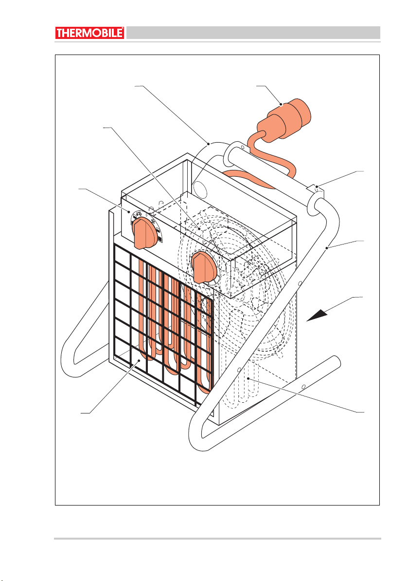
2.3 Hoofdcomponenten (Fig. 4)
A Bedieningspaneel
B ventilator
C Draagbeugel
D Netspanningssteker
E Ophangogen
F Luchtinlaatrooster
G Verwarmingselementen
H Luchtuitblaasrooster
A Keuzeschakelaar
* 0 = Uit
1 = Ventileren (BX 9 beperkte
capaciteit).
2 = Verwarmen, halve of 2/3
capaciteit. (Ventilator wordt
thermostatisch bestuurd).
3 = Verwarmen, maximale capaciteit.
(Ventilator wordt thermostatisch
bestuurd.)
4 = Ventileren, niet verwarmen.
(BX9 ventileert maximaal).
5 = Verwarmen, halve of 2/3
capaciteit. (Ventilator wordt continu
bestuurd).
6 = Verwarmen, maximale capaciteit.
(Ventilator wordt continu bestuurd).
B Regelthermostaat, traploos instelbaar
van 0 - 35 °C
3 VOORBEREIDINGEN
3.1 Verpakking verwijderen
1. Verwijder de verpakking van de kachel.
2. Controleer de inhoud op eventuele
schade.
3. Lees de gebruiksaanwijzing.
2.4 Regelthermostaat
De kachel heeft een regelthermostaat die de
kachel uitschakelt als de vooraf ingestelde
temperatuur van de omgevingslucht wordt
bereikt.
De kachels BX9 en BX15 hebben een
thermostaat met dubbele schakelcapaciteit.
2.5 Bedieningspaneel (fig. 3)
De kachel is uitgevoerd met een 7-standen
keuzeschakelaar (A) en een
regelthermostaat (B).
BX3 / BX9 / BX15 40.020.959 - rev. 01 - 2007 7
Nederlands
3.2 Installatie
1. Controleer of de kachel op de juiste
spanning / frequentie wordt aangesloten.
WAARSCHUWING
Kachel niet aansluiten indien de
spanning / frequentie afwijkt van de
waarden zoals vermeld op de
typeplaat.
2. Zorg voor een stabiele opstelling van de
kachel.
Plaats de kachel altijd horizontaal
met de voetdoppen onder.
3. Maak gebruik van de ophangogen indien
de kachel wordt opgehangen.
Respecteer in dit geval de maten die
vermeld staan op sticker (B), fig. 2 & 5.
4GEBRUIK
4.1 Inschakelen (fig. 3)
Verwarmen:
1. Zet de keuzeschakelaar (A) op stand 2 of
3 voor intermitterend verwarmen
(thermostatisch bestuurd).
2. Zet de keuzeschakelaar op 5 of 6 voor
continu verwarmen.
4.2 Uitschakelen (fig. 3)
1. Zet de keuzeschakelaar (A) op stand 0.
4.3 Temperatuur regelen (fig. 4)
1. Draai de thermostaatknop (A) in de juiste
stand voor de gewenste
omgevingstemperatuur.
Ventileren:
1. Zet de keuzeschakelaar (A) op stand 1.
(Alleen BX 9 ventileert beperkt.)
2. Zet de keuzeschakelaar op stand 4.
(Ook BX 9 ventileert nu volledig.)
Het wisselen van 2 fasedraden in de
steker heeft geen invloed op de
werking van de 3-fasen kachel.
De NUL pen van 5-polige steker niet
gebruiken.
8 40.020.959 - rev. 01 - 2007 BX3 / BX9 / BX15
Nederlands
5 ONDERHOUD
/i
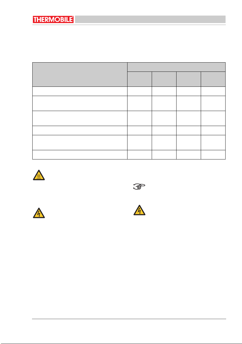
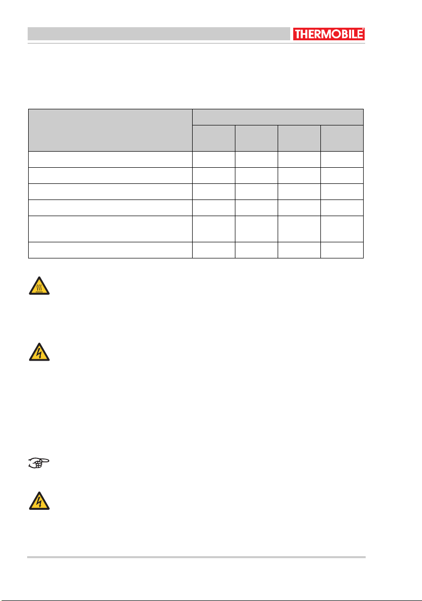
5.1 Onderhoudstabel
Registreer na elk winterseizoen het
onderhoud in de annex achterin dit boek.
Beschrijving Periode
Iedere
week
Iedere
maand
Ieder half
jaar
Ieder jaar
Verwijder stof en aanslag van de kachel. X
Controleer de kachel (in een schone
Dealer
omgeving).
Controleer de kachel (in een stoffige
Dealer
omgeving).
Controleer en reinig het inlaatrooster X
Controleer de ventilator op juiste werking, vuil
X
en beschadigingen.
Controleer de bedrading van de kachel. X
Heet
6STORINGEN
Raak het uitblaasrooster niet aan!
Wacht met het onderhoud totdat dit is
afgekoeld.
Let op als de netspanning
ingeschakeld is tijdens het
storingzoeken.
5.2 Algemeen
WAARSCHUWING
Neem de netspanningssteker uit de
contactdoos tijdens het onderhoud.
WAARSCHUWING
Neem de netspanningssteker uit de
contactdoos tijdens een reparatie.
Als de kachel voor langere tijd opgeslagen
wordt:
1. Schakel de kachel uit.
2. Neem de netspanningssteker uit de
contactdoos.
3. Reinig de kachel.
BX3 / BX9 / BX15 40.020.959 - rev. 01 - 2007 9
Nederlands
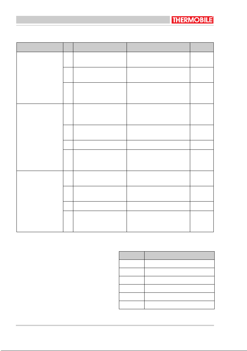
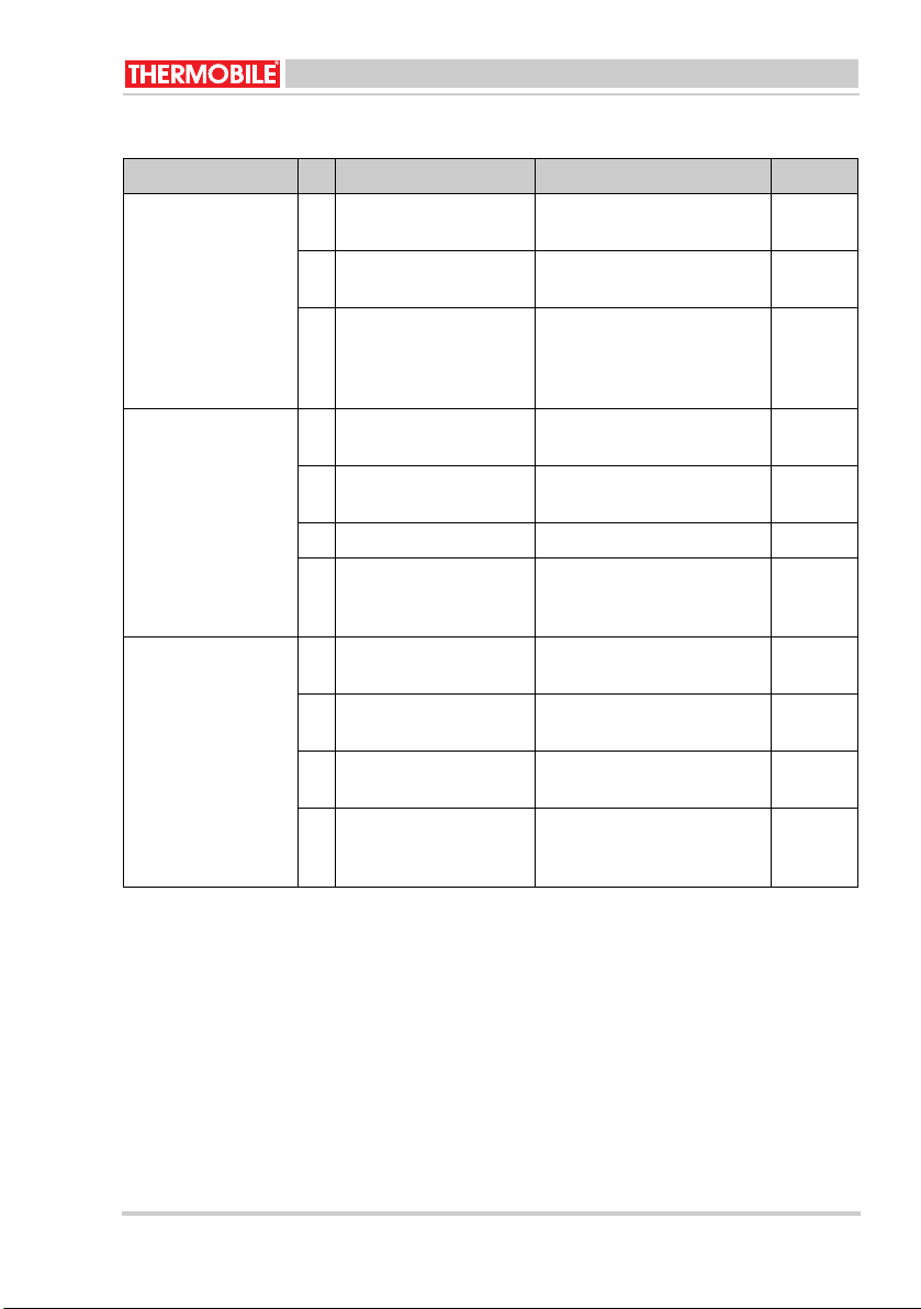
6.1 Tabel storingzoeken
/i
Storing Oorzaak Oplossing Actie
De kachel werkt niet. 1 De kachel heeft geen
spanning.
2 Defect in het bedie-
ningspaneel.
3 Fase - NUL draden ver-
Controleer de elektrische
Gebruiker
aansluiting.
Repareer of vervang het
Dealer
bedieningspaneel.
Herstel de verbinding. Gebruiker
wisseld in een 5-polige
steker/contrasteker.
Ventilator draait niet,
geen warmte.
4 De thermostaat is inge-
steld op een te lage
Corrigeer de instelling. Gebruiker
temperatuur.
5 Zekering defect in uw
installatie.
Vervang de zekering.
(Draai deze goed vast.)
Gebruiker
6 Ventilatormotor stuk. Vervang de ventilatormotor. Dealer
7 Kabel of verlengkabel
Herstel de verbinding. Gebruiker
afgekneld.
(Draad onderbroken).
Stand 2, 3: ventilator
draait normaal, weinig warmte 50%.
8 Zekering defect in uw
installatie.
9 Kabel of verlengkabel
Vervang de zekering.
Gebruiker
(Draai deze goed vast.)
Herstel de verbinding. Gebruiker
defect.
10 Kachel werkt op 2 fasen. Herstel de verbinding. Gebruiker
11 Eén losse of verbrande
Herstel de verbinding. Gebruiker
draad in de steker/contra-verlengkabel.
Noteer de onderhoudsgegevens in tabel A in
de annex achterin dit boek.
7 RESERVEONDERDELEN
Raadpleeg de dealer voor het gebruik van
reserveonderdelen.
8.1 Uitleg van het elektrische schema
/i
Pos. Beschrijving
A Verwarmingselement
B Ventilatormotor
C Keuzeschakelaar
8 TECHNISCHE INFORMATIE
• Zie voor technische specificaties tabel B
in de annex achterin dit boek.
• Zie voor het elektrische schema het
D Regelthermostaat
E Maximaalthermostaat
F Serieweerstand
schema C in de annex achterin dit boek.
10 40.020.959 - rev. 01 - 2007 BX3 / BX9 / BX15
9 EG-VERKLARING VAN
OVEREENSTEMMING
THERMOBILE INDUSTRIES B.V.,
Konijnenberg 80, NL-4825 BD BREDA,
verklaart geheel onder eigen
verantwoordelijkheid dat de producten:
ELEKTRISCHE LUCHTVERHITTERS BX3 /
BX9 / BX15
voldoen aan de volgende EG-richtlijnen:
Machinerichtlijn: 98/37/EEC
Laagspanningsrichtlijn: 72/23/EEC
EMC-richtlijn: 89/336/EEC
Nederland, Breda,
01-10-2007
R.E. Merkenhof
Managing Director
Nederlands
BX3 / BX9 / BX15 40.020.959 - rev. 01 - 2007 11
English
Onl
English
Contents
Safety instructions .....................................13
Introduction................................................14
Preparations ..............................................14
Use ............................................................14
Maintenance ..............................................16
Faults.........................................................16
Spare parts ................................................17
Technical information.................................17
EU Declaration of conformity .....................18
Foreword
This manual contains the instructions for use
of the heater shown on the cover. The
information in this manual is important for the
correct and safe use of the heater.
Identification of the product
The identification plate is attached to the side
of the heater. The identification plate contains
the following data:
A Model
B Voltage
C Input
D Current
E Frequency
F Protection level against dust and
moisture
G Production code
H Year of manufacture
I Serial number
Environment
Note
The heater is made of various metals
and synthetic materials. The heater
also contains electronic parts, which
must be treated as electronic waste.
Please contact your dealer for further
information.
y applicable to the European
Union
Waste disposal of electric &
electronic equipment for business
use.
For further information regarding the
disposal of products for business use
at the end of their life span, please
contact your dealer or distributor in
your country. This product may not
be disposed of together with
commercial waste or as commercial
waste.
Service and technical support
Please contact your dealer or the
manufacturer for information about the
heater. Make sure you have the following
data at hand: type and serial number of the
heater.
Warranty and liability
For warranty and liability, see the general
warranty regulations.
12 40.020.959 - rev. 01 - 2007 BX3 / BX9 / BX15
English
1 SAFETY INSTRUCTIONS
1.1 Pictograms in this manual Caution
Indicates risk of damage to the
appliance.
Warning
Indicates a dangerous situation that
may lead to death or serious injuries.
Warning
Always switch off power when
performing maintenance or repairs on
the convector heater!
Hot
Some surfaces may be hot! Wait until
these parts have sufficiently cooled
down before performing
maintenance.
Suggestions and tips to facilitate the
specified tasks or actions.
1.2 Use this product for its intended use
The heaters described in this manual have
been designed for heating building sites and
huts, storage places, shops, offices and
homes.
1.3 General instructions Warning
• Read this manual carefully
before using the heater.
• Keep this document with the
heater.
• Follow the described procedures.
• Only connect the heater to a
socket that has been correctly
earthed that meets the standards
that apply in the relevant country.
Consult an expert if in any doubt.
• Make sure that any extension
cable used has the required
weight for the heater.
• Fully unwind a cable reel.
• Do not cover the heater. Make
sure the air INLET and OUTLET
are not obstructed.
• Do not insert any objects into the
heater.
• Do not place any inflammable
objects in front of the heater and
make sure you keep sufficient
distance.
• Do not use the heater in rooms
where there is an explosion risk
or in rooms where there are
aggressive gases such as
ammonia, glue or paint thinners.
• Only perform repair and
maintenance activities when the
heater has sufficiently cooled
down and after removing the plug
from the socket.
• Never clean the inside of the
heater using water but use
compressed air.
• Make sure you immediately
disconnect the power supply
when there are visible faults or
defects and have the heater
repaired by an expert.
• At all times take into account the
applicable safety regulations with
regard to the prevention of
danger and accidents.
BX3 / BX9 / BX15 40.020.959 - rev. 01 - 2007 13
English
2 INTRODUCTION
2.1 Purpose
This portable heater works electrically and is
equipped with a fan. The heater has been
designed for horizontal indoor installation
(which can be permanent).
2.2 Principle of operation
Heating elements have been installed in the
heater.
The fan blows air over the heating elements.
The fan can be controlled continuously and
thermostatically.
The maximum thermostat switches off the
heater when overheated. Overheating occurs
when the air flow is too low or when the shaft
is dirty on the inside. Once it has cooled
down, the heater will switch on automatically
(automatic reset).
Make sure thereafter that there is better air
flow.
2.3 Main components (Fig. 4)
A Operating panel
BFan
C Supporting bracket
D Mains plug
E Suspension eyes
F Air-inlet grid
G Heating elements
H Air-outlet grid
2.4 Control thermostat
The heater has a control thermostat that
switches off the heater when the ambient
temperature set in advance has been
reached.
The BX9 and BX15 heaters have a
thermostat with double switching capacity.
2 = Heat, half or 2/3 capacity. (The
fan is thermostatically controlled.)
3 = Heat, maximum capacity. (The
fan is thermostatically controlled.)
4 = Ventilate, do not heat
(BX9 ventilates to full capacity)
5 = Heat, half or 2/3 capacity. (The
fan is continuously controlled.)
6 = Heat, maximum capacity. (The
fan is continuously controlled.)
B Control thermostat, infinitely variable
from 0 - 35 °C
3 PREPARATIONS
3.1 Remove packaging
1. Remove packaging from the heater.
2. Check the contents for any damage.
3. Read the instructions for use.
3.2 Installation
1. Check whether the heater is connected
to the correct voltage/frequency.
Warning
Do not connect the heater if the
voltage/frequency deviates from the
values as listed on the nameplate.
2. Make sure that the heater has a stable
set-up.
Always set the heater horizontally
with the foot caps at the bottom.
3. Use the suspension eyes if the heater is
being suspended. Respect in this case
the sizes listed on the label (B), figs. 2 &
5.
2.5 Operating panel (fig. 3)
The heater has a 7-position selector switch
(A) and a control thermostat (B).
A Selector switch
* 0 = Off
1 = Ventilate (BX 9 limited capacity).
14 40.020.959 - rev. 01 - 2007 BX3 / BX9 / BX15
4USE
4.1 Switching on (fig. 3)
Heat:

1. Set the selector switch (A) to position 2 or
3 for intermittent heating (thermostatically
controlled).
2. Set the selector switch to position 5 or 6
for continuous heating.
Ventilate:
1. Set the selector switch (A) to position 1.
(Only BX 9 ventilates to a limited degree.)
2. Set the selector switch to position 4.
(The BX 9 will now also fully ventilate.)
Exchanging 2 phase wires in the plug
will not influence the operation of the
3-phase heater.
Do not use the ZERO pin of the 5pole connector.
4.2 Switching off (fig. 3)
1. Set the selector switch (A) to position 0.
4.3 Regulating the temperature (fig. 4)
1. Turn the thermostat button (A) to the
correct position for the required ambient
temperature.
English
BX3 / BX9 / BX15 40.020.959 - rev. 01 - 2007 15
English
5 MAINTENANCE
/i
5.1 Maintenance table
Use the annex at the back of this manual to
record the maintenance after each winter.
Description Period
Weekly Monthly Every six
Annually
months
Remove dust and deposits from the heater. X
Check the heater (in a clean environment). Dealer
Check the heater (in a dusty environment). Dealer
Check and clean the inlet grid. X
Check the correct operation of the fan and
X
check for dirt and damages.
Check the heater's wiring. X
Hot
Do not touch the outlet grid!
Wait until it has cooled down before
performing maintenance.
5.2 General
Warning
Remove the mains plug from the
socket during maintenance.
For long-term storage of the heater:
1. Switch off the heater.
2. Remove the mains plug from the socket.
3. Clean the heater.
6FAULTS
Make sure that the mains voltage is
connected during troubleshooting.
Warning
Remove the mains plug from the
socket during repair work.
16 40.020.959 - rev. 01 - 2007 BX3 / BX9 / BX15
English
6.1 Troubleshooting table
/i
Fault Cause Solution Action
The heater is not
functioning.
1 The heater has no volt-
age.
2 Defect in the operating
panel.
3 Phase - exchange the
Check the electrical connec-
User
tion.
Repair or replace the operat-
Dealer
ing panel.
Repair the connection. User
ZERO wires in a 5-pole
connector/female connector.
The fan does not turn
and there is no heat.
4 The thermostat is set to
a too low temperature.
5 Fuse is faulty in your
system.
Correct the settings. User
Replace the fuse. (Make sure
User
it is tight.)
6 Fan motor is broken. Replace the fan motor. Dealer
7 Cable of the extension
Repair the connection. User
cable has been pinched.
(Wire interrupted.)
Positions 2 and 3:
The fan turns as normal but there is little
heat, 50%.
8 Fuse is faulty in your
system.
9 Cable of the extension
cable faulty.
10 Heater functions on 2
Replace the fuse. (Make sure
User
it is tight.)
Repair the connection. User
Repair the connection. User
phases.
11 One loose or burnt cable
Repair the connection. User
in the plug/counter
extension cable.
Record the maintenance details in table A in
the annex at the back of this manual.
7 SPARE PARTS
Contact the dealer for the use of spare parts.
8 TECHNICAL INFORMATION
• For technical specifications, see table B
in the annex at the back of this manual.
• For the electrical circuit diagram, refer to
diagram C in the annex at the back of this
manual.
BX3 / BX9 / BX15 40.020.959 - rev. 01 - 2007 17

English
8.1 Explanation of the electrical circuit diagram
/i
Pos. Description
A Heating element
B Fan motor
CSelector switch
D Control thermostat
E Maximum thermostat
F Series resistance
9 EU DECLARATION OF
CONFORMITY
THERMOBILE INDUSTRIES B.V.,
Konijnenberg 80, NL-4825 BD BREDA,
assumes full responsibility when declaring
that products:
BX3 /BX9 / BX15 ELECTRICAL AIR
HEATERS
meet the following EU directives:
Machine directive: 98/37/EEC
Low voltage directive: 72/23/EEC
EMC directive: 89/336/EEC
The Netherlands, Breda,
01-10-2007
R.E. Merkenhof
Managing Director
18 40.020.959 - rev. 01 - 2007 BX3 / BX9 / BX15

Deutsch
Gilt
n
G
e
n
Gilt
Deutsch
Inhalt
Sicherheitshinweise .................................. 20
Einführung................................................. 21
Vorbereitungen.......................................... 22
Verwendung.............................................. 22
Wartung..................................................... 23
Störungen.................................................. 23
Ersatzteile ................................................. 24
Technische Informationen......................... 25
EG-Konformitätserklärung ........................ 25
Vor wort
Dieses Handbuch enthält die
Bedienungsanleitung für den auf dem
Umschlag aufgeführten Heizer. In dieser
Betriebsanleitung sind wichtige
Informationen in Bezug auf die
ordnungsgemäße und sichere Funktion des
Heizers enthalten.
Identifikation des Produktes
Das Typenschild ist an der Seite des Heizers
befestigt. Auf dem Typenschild finden Sie die
folgenden Daten:
A Modell
B Spannung
C Input
DStrom
E Frequenz
F Schutzklasse gegen Staub und
Feuchtigkeit
G Herstellungscode
H Herstellungsjahr
I Seriennummer
Entsorgung
Hinweis
Der Heizer besteht aus
verschiedenen Metallen und
Kunststoffen. Der Heizer enthält
ferner elektronische Komponenten,
die als elektronischer Abfall zu
entsorgen sind. Weiterführende
Informationen hält Ihr Fachhändler
für Sie bereit.
nur für die Europäische Union
nur für die Europäische Union
Abfallentsorgung von elektrischer
Abfallentsorgung von elektrischer
elektronischer Ausrüstung für den
und elektronischer Ausrüstung für
gewerblichen Gebrauch.
den gewerblichen Gebrauch.
Für weitere Informationen über die E
Für weitere Informationen über die
Entsorgung von Produkten für den
von Produkten für den gewerblichen
gewerblichen Gebrauch am Ende
Ende ihrer Lebensdauer nehmen Sie
ihrer Lebensdauer nehmen Sie bitte
mit Ihrem Händler oder Vertrieb in Ihr
Kontakt mit Ihrem Händler oder
Dieses Produkt darf weder zusamme
Vertrieb in Ihrem Land auf. Dieses
als Hausmüll entsorgt werden.
Produkt darf weder zusammen mit
noch als Hausmüll entsorgt werden.
Kundendienst und technische Unterstützung
Weitere Informationen zum Heizer hält Ihr
Händler oder Hersteller bereit. Achten Sie
darauf, dass Sie dann folgende Angaben zur
Hand haben: Typ und Seriennummer des
Heizers.
Garantie und Haftung
Die Bestimmungen in Bezug auf die Garantie
und Haftung finden Sie unter den
allgemeinen Garantiebedingungen.
BX3 / BX9 / BX15 40.020.959 - rev. 01 - 2007 19

Deutsch
1 SICHERHEITSHINWEISE
1.1 Piktogramme in dieser Betriebsanleitung
Vor sich t
Gefahr einer Produktbeschädigung
Achtung
Gefährliche Situationen, die den Tod
oder ernsthafte Verletzungen zur
Folge haben können.
Achtung
Bei Wartungs- oder
Reparaturarbeiten am Heizer immer
die Stromversorgung ausschalten!
Heiß
Einige Flächen können heiß sein!
Warten Sie mit der Ausführung der
Wartungsarbeiten, bis diese Bereiche
abgekühlt sind.
Hinweise und Tipps, um die
Ausführung der betreffenden
Aufgaben oder Handlungen zu
vereinfachen.
1.2 Das Produkt darf nur gemäß seinem bestimmungsgemäßen Verwendungszweck betrieben werden.
Die in dieser Anleitung beschriebenen Heizer
sind auf das Heizen von Baustellen und
Baubaracken, Lagerplätzen, Geschäften,
Büros und Häusern ausgelegt.
1.3 Allgemeine Anweisungen Achtung
• Lesen Sie zunächst dieses
Handbuch aufmerksam durch,
bevor Sie den Heizer zum
Einsatz bringen.
• Bewahren Sie dieses Dokument
in unmittelbarer Nähe des
Heizers auf.
• Befolgen Sie die beschriebene
Verfahrensweise.
• Den Heizer nur an eine korrekt
geerdete Steckdose
anschließen, die den national
geltenden Normen entspricht. Im
Zweifelsfall einen Experten zu
Rate ziehen.
• Bei Verwendung eines
Verlängerungskabels darauf
achten, dass es der Leistung des
Heizers entspricht.
• Kabelwinde vollständig abrollen.
• Den Heizer nicht abdecken. EIN-
und AUSTRITT der Luft
freilassen.
• Keine Gegenstände in den
Heizer stecken.
• Keine brennbaren Gegenstände
vor den Heizer stellen,
ausreichend großen Abstand
einhalten.
• Den Heizer nicht in
explosionsgefährlichen Räumen
oder Räumen mit aggressiven
Gasen wie Ammoniak, Leim und
Farbverdünnern verwenden.
• Führen Sie ausschließlich
Reparatur- und
Wartungsarbeiten aus, wenn der
Heizer ausreichend abgekühlt ist
und nachdem der Stecker aus
der Steckdose gezogen wurde.
• Die Innenseite des Heizers
keinesfalls mit Wasser reinigen,
sondern mit Druckluft.
20 40.020.959 - rev. 01 - 2007 BX3 / BX9 / BX15

Deutsch
Achtung
• Bei sichtbaren Mängeln den
Heizer sofort spannungsfrei
machen und von einem
Fachmann reparieren lassen.
• Die geltenden
Sicherheitsvorschriften zur
Vermeidung von Gefahren und
Unfällen jederzeit beachten.
2 EINFÜHRUNG
2.1 Ziel
Dieser tragbare Heizer funktioniert elektrisch
und ist mit Ventilator ausgestattet. Der Heizer
ist auf (eventuell ortsfeste) horizontale
Innenaufstellung ausgelegt.
2.2 Funktionsprinzip
Im Heizer sind Heizelemente angebracht.
Ein Ventilator bläst Luft über die
Heizelemente.
Der Ventilator kann sowohl kontinuierlich als
auch mittelst Thermostat gesteuert werden.
Bei Überhitzung schaltet der
Maximalthermostat den Heizer aus.
Überhitzung tritt ein, wenn der Luftstrom zu
gering ist oder die Innenseite des Köchers
verschmutzt ist. Nach dem Abkühlen schaltet
sich der Heizer selbsttätig wieder ein (AutoReset).
Sorgen Sie dann für einen besseren
Luftstrom.
2.3 Hauptkomponenten (Abb. 4)
A Bedienpult
B Ventilator
C Tragebügel
D Netzstecker
E Hängeösen
F Lufteintrittsgitter
G Heizelemente
H Luftaustrittsgitter
2.4 Regelthermostat
Der Heizer besitzt ein Regelthermostat, der
ihn ausschaltet, sobald die Umgebungsluft
die zuvor eingestellte Temperatur erreicht.
Die Heizer BX9 und BX15 sind mit einem
Thermostat mit doppelter Schaltleistung
ausgestattet.
2.5 Bedienpult (Abb. 3)
Der Heizer ist mit einem Wahlschalter (A) mit
7 Positionen und einem Regelthermostat (B)
augestattet.
BX3 / BX9 / BX15 40.020.959 - rev. 01 - 2007 21

Deutsch
AWahlschalter
*0 = Aus
1 = Ventilieren (BX 9 begrenzte
Leistung).
2 = Heizen, halbe oder 2/3 Leistung.
(Ventilator mit Thermostatsteuerung.)
3 = Heizen, maximale Leistung.
(Ventilator mit Thermostatsteuerung.)
4 = Ventilieren (nicht heizen).
(BX9 ventiliert maximal).
5 = Heizen, halbe oder 2/3 Leistung.
(Ventilator mit kontinuierlicher
Steuerung.)
6 = Heizen, maximale Leistung.
(Ventilator mit kontinuierlicher
Steuerung.)
B Regelthermostat, stufenlos einstllbar von
0-35 °C
3 VORBEREITUNGEN
3.1 Verpackung entfernen
1. Entfernen Sie die Verpackung des
Heizers.
2. Überprüfen Sie den Inhalt auf eventuelle
Beschädigungen.
3. Lesen Sie aufmerksam die
Betriebsanleitung.
3.2 Installation
1. Überprüfen, ob der Heizer an die
korrekte Spannung/Frequenz
angeschlossen wird.
Achtung
Heizer nicht anschließen, wenn die
Spannung/Frequenz von den auf
dem Typenschild vermerkten Werten
abweicht.
2. Sorgen Sie für eine stabile Aufstellung
des Heizers.
Den Heizer mit Hilfe der Füße
horizontal aufstellen.
3. Beim Aufhängen des Heizers Hängeösen
verwenden. In dem Fall sind die auf dem
Aufkleber (B), Abb. 2 & 5, genannten
Maße zu beachten.
4 VERWENDUNG
4.1 Einschalten (Abb. 3)
Heizen:
1. Den Wahlschalter (A) auf Position 2 oder
3 für intermittierendes Heizen einstellen
(Thermostatgesteuert).
2. Den Wahlschalter zur kontinuierlichen
Heizung auf 5 oder 6 einstellen.
Ventilieren:
1. Schalten Sie den Wahlschalter (A) auf 1.
(Nur BX 9 ventiliert eingeschränkt.)
2. Schalten Sie den Wahlschalter auf 4.
(Auch BX 9 ventiliert jetzt vollständig.)
Der Austausch von zwei
Phasendrähten hat keinen Einfluss
auf die Funktionsweise des 3Phasen-Heizers.
Den NULL-Stift des 5-poligen
Steckers nicht verwenden.
4.2 Ausschalten (Abb. 3)
1. Schalten Sie den Wahlschalter (A) auf 0.
4.3 Temperatur einstellen (Abb. 4)
1. Den Thermostatschalter (A) für die
gewünschte Umgebungstemperatur in
die entsprechende Position drehen.
22 40.020.959 - rev. 01 - 2007 BX3 / BX9 / BX15

Deutsch
5 WARTUNG
/i
5.1 Wartungstabelle
Registrieren Sie bitte nach jeder
Wintersaison die Wartungsarbeiten im
Anhang des Handbuchs.
Beschreibung Periode
Wöchentlich
Monatlich Alle halbe
Jahre
Jährlich
Staub und Beschlag vom Heizer entfernen. X
Den Heizer kontrollieren (in einer sauberen
Händler
Umgebung).
Den Heizer kontrollieren (in einer staubigen
Händler
Umgebung).
Das Eintrittgitter kontrollieren und reinigen. X
Den Ventilator auf korrekte Funktionsweise,
X
Verschmutzung und Beschädigungen hin
überprüfen.
Die Verdrahtung des Heizers kontrollieren. X
Heiß
6 STÖRUNGEN
Das Ausblasgitter auf keinen Fall
berühren!
Nehmen Sie die Wartungsarbeiten
erst in Angriff, wenn es ausreichend
abgekühlt ist.
Passen Sie auf, wenn bei der
Störungssuche die Netzspannung
eingeschaltet ist.
Achtung
5.2 Allgemein
Achtung
Ziehen Sie während der Reparatur
den Netzstecker aus der Steckdose.
Ziehen Sie während der Wartung den
Netzstecker aus der Steckdose.
Falls der Heizer für längere Zeit gelagert
wird:
1. Schalten Sie den Heizer aus.
2. Ziehen Sie den Netzspannungsstecker
aus der Steckdose.
3. Reinigen Sie den Heizer.
BX3 / BX9 / BX15 40.020.959 - rev. 01 - 2007 23

Deutsch
6.1 Tabelle Störungssuche
/i
Störung Ursache Lösung Hand-
lung
Der Heizer funktioniert nicht.
1 Der Heizer hat keine
Spannung.
Kontrollieren Sie den elektrischen Anschluss.
2 Defekt am Bedienpult. Reparieren oder ersetzen Sie
Benutzer
Händler
das Bedienpult.
3 Phase-Null-Drähte in
Verbindung reparieren. Benutzer
einem 5-poligen Stecker/Gegenstecker vertauscht.
Ventilator läuft nicht,
keine Wärme.
4 Der Thermostat ist auf
eine zu niedrige Tempe-
Korrigieren Sie die Einstel-
lung.
Benutzer
ratur eingestellt.
5 Sicherung Ihrer Anlage
defekt.
6 Ventialtormotor ist
beschädigt.
7 Kabel oder Verlänge-
Sicherung ersetzen. (Fest
Benutzer
anziehen.)
Den Ventilatormotor austau-
Händler
schen.
Verbindung reparieren. Benutzer
rungskabel abgeklemmt. (Draht
unterbrochen.)
Position 2, 3: Ventilator läuft normal,
wenig Wärme, 50 %.
8 Sicherung Ihrer Anlage
defekt.
9 Kabel oder Verlänge-
Sicherung ersetzen. (Fest
Benutzer
anziehen.)
Verbindung reparieren. Benutzer
rungskabel defekt.
10 Heizer arbeitet mit 2
Verbindung reparieren. Benutzer
Phasen.
11 Ein lockerer oder ver-
Verbindung reparieren. Benutzer
brannter Draht im Stecker/Gegenstecker oder
im Verlängerungskabel.
Notieren Sie die ausgeführten
Wartungsdaten in der Tabelle A im Anhang
im hinteren Teil dieses Handbuchs.
7 ERSATZTEILE
Wenden Sie sich für die Verwendung von
Zubehörteilen an Ihren Händler.
24 40.020.959 - rev. 01 - 2007 BX3 / BX9 / BX15

Deutsch
8 TECHNISCHE INFORMATIONEN
• Die technischen Daten finden Sie in
Tabelle B im Anhang im hinteren Teil
dieses Handbuchs.
• Den Schaltplan finden Sie unter
Schaltplan C im Anhang im hinteren Teil
dieses Handbuchs.
8.1 Erklärungen zu den Schaltplänen
/i
Pos. Beschreibung
A Heizelement
B Ventilatormotor
C Wahlschalter
D Regelthermostat
E Maximalthermostat
F Serienwiderstand
9 EG-KONFORMITÄTSERKLÄRUNG
THERMOBILE INDUSTRIES B.V.,
Konijnenberg 80, NL-4825 BD BREDA,
erklärt in eigener Verantwortung, dass die
Produkte:
ELEKTRISCHE LUFTHEIZER BX3 /BX9 /
BX15
den nachstehenden EG-Richtlinien genügen:
Maschinenrichtlinie: 98/37/EG
Niederspannungsrichtlinie: 72/23/EG
EMC-Richtlinie: 89/336/EG
Niederlande, Breda,
01-10-2007
R.E. Merkenhof
Managing Director
BX3 / BX9 / BX15 40.020.959 - rev. 01 - 2007 25

Français
Applicabl
Français
Table des matières
Consignes de sécurité ...............................27
Introduction................................................28
Préparations ..............................................29
Emploi........................................................29
Entretien ....................................................31
Pannes.......................................................31
Pièces de rechange...................................32
Renseignements techniques .....................32
Déclaration de conformité CE....................33
Préface
Ce manuel comprend le mode d’emploi de
l’appareil de chauffage mentionné sur la
couverture. Les renseignements contenus
dans ce manuel sont importants pour un
emploi correct et sûr de l’appareil de
chauffage.
Identification du produit
La plaquette d'identification est fixée sur le
côté de l’appareil de chauffage. La plaquette
d'identification contient les données
suivantes:
A Modèle
B Voltage
CEntrée
D Courant
E Fréquence
F Classe de protection contre la poussière
et l’humidité
G Code de production
H Année de fabrication
I Numéro de série
Environnement
Remarque
L’appareil de chauffage d'air chaud
est constitué de divers métaux et
plastiques. Le générateur contient
également des pièces électroniques,
lesquelles doivent être traitées
comme déchets électroniques.
Contactez votre concessionnaire
pour plus de renseignements.
e uniquement dans
l’Union européenne
Mise au rebut des équipements
électriques et électroniques à
usage commercial
Pour obtenir de plus amples
informations relatives à la mise au
rebut de produits à usage
commercial à la fin de leur durée de
vie, veuillez contacter votre
revendeur ou distributeur dans votre
pays. Ce produit ne doit pas être jeté
avec les déchets commerciaux ou
comme déchet commercial.
Service et support technique
Pour plus de renseignements sur l’appareil
de chauffage, contactez votre
concessionnaire ou le fabricant. Préparer les
données suivantes: type et numéro de série
de l’appareil de chauffage.
Conditions de garantie et responsabilité
Pour la garantie et la responsabilité, voir les
conditions générales de garantie.
26 40.020.959 - rev. 01 - 2007 BX3 / BX9 / BX15

Français
1 CONSIGNES DE SÉCURITÉ
1.1 Pictogrammes dans ce manuel Précaution
Signifie le risque d'endommagement
de l'appareil.
Avertissement
Signifie une situation dangereuse,
pouvant causer la mort ou des
blessures graves.
Avertissement
Lors de travaux d'entretien ou de
réparation sur le générateur d'air
chaud, il faut toujours couper le
courant électrique !
Chaud
Certaines surfaces risquent d'être
chaudes ! Attendre que ces pièces
refroidissent suffisamment avant
d’entreprendre l’entretien.
Suggestions et conseils afin de
simplifier l'exécution de certaines
tâches ou activités.
1.2 Ce produit ne doit être utilisé qu'aux fins auxquelles il a été destiné.
Les appareils de chauffage décrits dans ce
manuel sont conçus pour le chauffage des
chantiers et baraques de chantier, entrepôts,
magasins, bureaux et habitations.
1.3 Consignes générales Avertissement
• Lire attentivement ce manuel
avant de mettre l’appareil de
chauffage en service.
• Conserver ce document près de
l’appareil de chauffage.
• Suivre les procédures décrites.
• Raccorder l’appareil de
chauffage à une prise de courant
correctement mise à la terre, qui
répond aux normes en vigueur
dans le pays. En cas de doute,
consultez un professionnel.
• En cas d’utilisation d’un câble
prolongateur, s’assurer qu'il est
suffisamment solide pour
l'appareil de chauffage.
• Déroulez complètement un
dévidoir de câble.
• Ne pas recouvrir l’appareil de
chauffage. Assurez-vous que
l'ADMISSION ET
L'ÉVACUATION sont dégagées.
• N’insérer aucun objet dans
l’appareil de chauffage.
• Ne placer aucun objet
inflammable sur l’appareil de
chauffage ; garder une distance
suffisante.
• Ne pas utiliser l’appareil de
chauffage dans locaux à
atmosphère explosible ni dans
des locaux contenant des
sources de gaz agressives
comme l'ammoniaque, la colle et
les diluants de peinture.
• N’effectuer de travaux de
réparation et d'entretien que si
l’appareil de chauffage a
suffisamment refroidi et qu’après
avoir retiré la fiche de la prise de
courant.
• Ne jamais nettoyer à l'eau
l’intérieur de l’appareil de
chauffage ; utiliser plutôt de l’air
comprimé.
BX3 / BX9 / BX15 40.020.959 - rev. 01 - 2007 27

Français
Avertissement
• En cas de constat d’anomalies
visibles sur l’appareil de
chauffage, le mettre
immédiatement hors tension et le
faire réparer par un
professionnel.
• Observer toujours la
réglementation de sécurité en
vigueur en matière de prévention
des risques et des accidents.
2 INTRODUCTION
2.1 But
Cet appareil de chauffage portable
fonctionne sur courant électrique et est
équipé d’un ventilateur. L’appareil de
chauffage est conçu pour une (éventuelle)
installation horizontale à l'intérieur.
2.2 Principe de fonctionnement
L’appareil de chauffage abrite des éléments
chauffants.
Le ventilateur souffle l’air par-dessus les
éléments chauffants.
Le ventilateur peut fonctionner aussi bien en
mode continu qu'en mode régulé par
thermostat.
En cas de surchauffe, le thermostat
maximum éteint l’appareil de chauffage. La
surchauffe survient si la circulation d'air est
trop faible ou si l’intérieur du tube est
encrassé. Après avoir refroidi, l’appareil de
chauffage se remet automatiquement en
marche (réinitialisation automatique).
Assurer ensuite une meilleure circulation
d’air.
2.3 Principaux composants (fig. 4)
A Panneau de commande
B ventilateur
C Étrier de support
D Fiche secteur
E Anneaux de suspension
F Grille d’admission d’air
G Éléments chauffants
H Grille de sortie d'air
2.4 Thermostat de régulation
L’appareil de chauffage possède un
thermostat de régulation qui éteint l’appareil
lorsque la température programmée de l’air
ambiant est atteinte.
Les appareils de chauffage BX9 et BX15
possèdent un thermostat à double capacité
de commutation.
28 40.020.959 - rev. 01 - 2007 BX3 / BX9 / BX15

Français
2.5 Panneau de commande (fig. 3)
Les appareils de chauffage sont équipés d’un
interrupteur-sélecteur à 7 positions (A) et
d’un thermostat de régulation (B).
A Interrupteur-sélecteur
* 0 = Arrêt
1 = Ventilation (BX 9 capacité
limitée).
2 = Chauffage, moitié ou 2/3 de
capacité. (le ventilateur fonctionne en
mode régulé par thermostat).
3 = Chauffage, capacité maximale (le
ventilateur fonctionne en mode
régulé par thermostat).
4 = Ventilation, sans chauffage
(BX9 ventile au maximum).
5 = Chauffage, moitié ou 2/3 de
capacité. (le ventilateur fonctionne en
mode continu).
6 = Chauffage, capacité maximale (le
ventilateur fonctionne en mode
continu).
B Thermostat de régulation, réglable en
continu de 0 à 35 °C
3PRÉPARATIONS
3.1 Enlever l'emballage
1. Enlever l'emballage de l’appareil de
chauffage.
2. Examinez le contenu quant à un éventuel
dommage.
3. Lisez le manuel d’utilisation.
3.2 Installation
1. Assurez-vous que l'appareil de chauffage
est branché à la tension/fréquence
appropriées.
Avertissement
Ne pas brancher l'appareil de
chauffage si la tension / fréquence
sont différentes des valeurs
indiquées sur la plaque
d'identification.
2. Assurer une installation stable de
l’appareil de chauffage.
Placez toujours l’appareil de
chauffage horizontalement sur des
bouchons de pied.
3. Utiliser les anneaux de suspension si
l'appareil de chauffage doit être
suspendu. Auquel cas, il faut respecter
les dimensions mentionnées sur
l’autocollant (B), fig. 2 & 5.
4EMPLOI
4.1 Mise en service (fig. 3)
Chauffage :
1. Mettre l’interrupteur-sélecteur (A) en
position 2 ou 3 pour chauffer par
intermittence (mode régulé par
thermostat).
2. Mettez l’interrupteur-sélecteur en position
5 ou 6 pour chauffer en mode continu.
Ventilation :
1. Mettre l’interrupteur-sélecteur (A) en
position 1.
(Sauf que le modèle BX 9 ventile de
manière limitée.)
BX3 / BX9 / BX15 40.020.959 - rev. 01 - 2007 29

Français
2. Mettre l’interrupteur-sélecteur en position
4.(Le modèle BX 9 ventile alors au
maximum.)
La permutation des 2 fils de phase
dans la fiche n'affecte pas le
fonctionnement l'appareil de
chauffage triphasé.
Ne pas utiliser la broche NEUTRE du
contacteur à 5 broches.
4.2 Arrêt (fig. 3)
1. Mettre l’interrupteur-sélecteur (A) en
position 0.
4.3 Réglage de la température (fig. 4)
1. Tourner le bouton du thermostat (A) dans
la position correspondant à la
température ambiante désirée.
30 40.020.959 - rev. 01 - 2007 BX3 / BX9 / BX15

Français
5 ENTRETIEN
/i
5.1 Table d'entretien
Après chaque hiver, il faut noter l'entretien
sur le tableau situé en annexe à la fin de ce
manuel.
Désignation Période
Chaque
semaine
Enlever la poussière et le tartre de l’appareil
Chaque
mois
X
de chauffage.
Contrôler l’appareil de chauffage (dans un
environnement propre).
Contrôler l’appareil de chauffage (dans un
environnement poussiéreux).
Vérifier et nettoyer la grille d’admission X
S’assurer que le ventilateur fonctionne correctement et n'est ni encrassé ni
endommagé.
Contrôler le câblage de l’appareil de
chauffage.
Chaud
6 PANNES
Ne pas toucher la grille de soufflage !
Attendre qu’elle refroidisse avant
d’entreprendre l’entretien de
l’appareil.
Veiller à ce que l’appareil soit sous
tension pendant la recherche de
pannes.
X
Chaque
semestre
Concessionnaire
Chaque
année
Concessionnaire
X
5.2 Généralités
Avertissement
Avant de procéder à l'entretien,
retirer la fiche secteur de la prise de
Avertissement
Avant de procéder à une réparation,
retirer la fiche secteur de la prise de
courant.
courant.
En cas d’entreposage prolongé de l’appareil
de chauffage :
1. Éteindre l’appareil de chauffage.
2. Retirer la fiche secteur de la prise de
courant.
3. Nettoyer l’appareil de chauffage.
BX3 / BX9 / BX15 40.020.959 - rev. 01 - 2007 31

Français
6.1 Tableau recherche des pannes
/i
Panne Cause Remède Action
L’appareil de chauffage ne fonctionne
pas.
1 L’appareil de chauffage
n'a pas de tension.
2 Défaillance dans le pan-
neau de commande.
3 Les fils phase et NEU-
Vérifier le raccordement
Utilisateur
électrique.
Réparer ou remplacer le panneau de commande.
Concessionnaire
Réparer le raccordement. Utilisateur
TRE sont permutés
dans une fiche/contrefiche à 5 broches.
Le ventilateur ne
tourne pas, pas de
production de chaleur.
4 Le thermostat est réglé
à une température trop
basse.
5 Le fusible de votre ins-
tallation est défectueux.
6 Le moteur du ventilateur
est défectueux.
7 Le câble ou le câble pro-
Corriger le réglage. Utilisateur
Remplacer le fusible. (Il faut
Utilisateur
bien le visser.)
Remplacer le moteur du ven-
tilateur.
Concessionnaire
Réparer le raccordement. Utilisateur
longateur est écrasé.
(Rupture de fil).
Positions 2, 3 : le
ventilateur tourne
normalement mais
donne peu de chaleur 50%.
8 Le fusible de votre ins-
tallation est défectueux.
9 Le câble ou le câble pro-
longateur est défectueux.
10 L’appareil de chauffage
Remplacer le fusible. (Il faut
Utilisateur
bien le visser.)
Réparer le raccordement. Utilisateur
Réparer le raccordement. Utilisateur
fonctionne sur 2 phases.
11 Présence d’un fil déta-
Réparer le raccordement. Utilisateur
ché ou brûlé dans la
fiche / contre-fiche du
câble prolongateur.
Noter les données d'entretien dans la table A
en annexe à la fin de ce manuel.
7 PIÈCES DE RECHANGE
Consulter le revendeur pour l’utilisation des
pièces de rechange.
8 RENSEIGNEMENTS TECHNIQUES
• Pour les spécifications techniques, voir le
tableau B en annexe à la fin de ce
manuel.
• Pour le circuit électrique, voir le schéma
en annexe à la fin de ce manuel.
32 40.020.959 - rev. 01 - 2007 BX3 / BX9 / BX15

Français
8.1 Explication du schéma électrique
/i
Pos. Désignation
A Élément chauffant
B Moteur du ventilateur
C Interrupteur-sélecteur
D Thermostat de régulation
E Thermostat maximum
F Résistance série
9 DÉCLARATION DE CONFORMITÉ
CE
THERMOBILE INDUSTRIES B.V.,
Konijnenberg 80, NL-4825 BD BREDA,
affirme entièrement sous sa propre
responsabilité que les produits :
APPAREILS DE CHAUFFAGE
ÉLECTRIQUES BX3 /BX9 / BX15
répondent aux directives CE suivantes:
Directive relative aux machines : 98/37/EEC
Directive pour tension basse: 72/23/EEC
Directive EMC: 89/336/EEC
Pays-Bas, Breda,
01-10-2007
R.E. Merkenhof
Managing Director
BX3 / BX9 / BX15 40.020.959 - rev. 01 - 2007 33

Español
Sól
j
Español
Índice
Instrucciones de seguridad........................35
Introducción ...............................................36
Preparaciones............................................37
Uso ............................................................37
Mantenimiento ...........................................39
Fallos .........................................................39
Piezas de repuesto....................................40
Información técnica....................................41
Declaración CE de conformidad................41
Prólogo
Este manual contiene las instrucciones de
uso del generador de aire caliente que se
muestra en la portada. La información de
este manual es importante para el uso
correcto y seguro del generador.
Identificación del producto
La placa de identificación está fijada en el
lateral del generador. En la placa de
identificación figuran los siguientes datos:
A Modelo
B Tensión
C Entrada
D Corriente
E Frecuencia
F Nivel de protección contra el polvo y la
humedad
G Código de fabricación
H Año de fabricación
I Número de serie
Medio ambiente
Nota
El generador de aire caliente está
fabricado de diversos materiales
metálicos y sintéticos. El generador
también contiene componentes
electrónicos, que tienen que tratarse
como desechos electrónicos.
Póngase en contacto con su
distribuidor para obtener más
información.
o aplicable en la Unión Europea
Desecho de residuos de equipos
eléctricos y electrónicos para uso
empresarial.
Para más información sobre el
desecho de productos para uso
empresarial al final de su vida útil,
póngase en contacto con el
distribuidor de su país.
Este producto no puede desecharse
unto con residuo comercial ni como
residuo comercial.
Servicio y asistencia técnica
Póngase en contacto con su distribuidor o
con el fabricante para obtener información
sobre el generador de aire caliente.
Asegúrese de tener a mano los siguientes
datos: el modelo y el número de serie del
generador.
Garantía y responsabilidad
Consulte los términos de garantía y
responsabilidad en las reglas generales de
garantía.
34 40.020.959 - rev. 01 - 2007 BX3 / BX9 / BX15
Español
1 INSTRUCCIONES DE SEGURIDAD
1.1 Símbolos utilizados en este manual
Precaución
Indica un riesgo de daños en el
aparato.
Advertencia
Indica una situación peligrosa que
puede provocar la muerte o lesiones
graves.
Advertencia
¡Desconecte siempre la alimentación
eléctrica cuando realice trabajos de
mantenimiento o reparaciones en el
generador de aire caliente por
convección!
Caliente
¡Algunas superficies pueden estar
calientes! Espere hasta que estos
componentes se hayan enfriado lo
suficiente antes de realizar el
mantenimiento.
Sugerencias y consejos para facilitar
las tareas o acciones especificadas.
1.2 Utilice este producto para su uso previsto
Los generadores de aire caliente descritos
en este manual se han diseñado para
calentar obras y barracones, almacenes,
comercios, oficinas y hogares.
1.3 Instrucciones generales Advertencia
• Lea este manual detenidamente
antes de utilizar el generador.
• Mantenga este documento con el
generador.
• Siga los procedimientos
descritos.
• Conecte el generador
únicamente a una toma de
corriente que tenga una toma de
tierra correcta que cumpla las
normas aplicables en el país
correspondiente. Consulte con
un experto en caso de duda.
• Asegúrese de que los cables
alargadores que se utilicen
tengan el peso adecuado para el
generador.
• Desenrolle totalmente una
bobina de cable.
• No cubra el generador.
Asegúrese de que la ENTRADA
y la SALIDA de aire no estén
obstruidas.
• No introduzca objetos en el
generador.
• No coloque objetos inflamables
delante del generador y
asegúrese de mantener la
distancia suficiente.
• No utilice el generador en
recintos donde haya riesgo de
explosión o en recintos donde
hay gases agresivos como
amoniaco, pegamento o
disolventes de pintura.
• Las actividades de reparación y
mantenimiento únicamente
deben realizarse cuando el
generador de aire caliente se
haya enfriado lo suficiente y
después de haber sacado el
enchufe de la toma de corriente.
• Nunca limpie el interior del
generador con agua. Utilice para
ello aire comprimido.
BX3 / BX9 / BX15 40.020.959 - rev. 01 - 2007 35

Español
Advertencia
• Asegúrese de desconectar
inmediatamente el suministro
eléctrico cuando haya fallos o
defectos visibles y haga que un
experto repare el generador.
• Tenga en cuenta en todo
momento los reglamentos de
seguridad aplicables con
respecto a la prevención de
riesgos y accidentes.
2 INTRODUCCIÓN
2.1 Propósito
Este generador portátil funciona con
electricidad y está equipado con un
ventilador. El generador se ha diseñado para
la instalación horizontal en interior (que
puede ser permanente).
2.2 Principio de funcionamiento
Se han instalado elementos calefactores en
el generador.
El ventilador sopla aire sobre los elementos
calefactores.
El ventilador puede controlarse de forma
continua o termostáticamente.
El termostato máximo desconecta el
generador cuando se sobrecalienta. El
sobrecalentamiento se produce cuando el
flujo de aire es demasiado bajo o cuando el
eje está sucio en el interior. Cuando se haya
enfriado, el generador se conectará
automáticamente (restablecimiento
automático).
Asegúrese posteriormente que haya un
mejor flujo de aire.
2.3 Componentes principales (fig. 4)
A Panel de manejo
B Ventilador
C Soporte de apoyo
D Enchufe de red
E Orejetas de suspensión
F Rejilla de entrada de aire
G Elementos calefactores
H Rejilla de salida de aire
2.4 Termostato de control
El generador tiene un termostato de control
que desconecta el generador cuando se
alcanza la temperatura ambiente
seleccionada con antelación.
Los generadores BX9 y BX15 tiene un
termostato con doble capacidad de
conmutación.
36 40.020.959 - rev. 01 - 2007 BX3 / BX9 / BX15

Español
2.5 Panel de manejo (fig. 3)
El generador tiene un interruptor selector de
7 posiciones (A) y un termostato de control
(B).
A Interruptor selector
* 0 = desconectado
1 = ventilación (BX 9 capacidad
limitada).
2 = calentamiento, mitad o 2/3 de
capacidad. (El ventilador se controla
mediante termostato).
3 = calentamiento, capacidad
máxima. (El ventilador se controla
mediante termostato).
4 = ventilación, sin calor
(BX9 ventila a plena capacidad)
5 = calentamiento, mitad o 2/3 de
capacidad. (El ventilador se controla
de forma continua).
6 = calentamiento, capacidad
máxima. (El ventilador se controla de
forma continua).
B Termostato de control, variable
infinitamente de 0 - 35 °C
3 PREPARACIONES
3.1 Desembalaje
1. Retire el embalaje del generador.
2. Compruebe el contenido para ver si
presenta daños.
3. Lea las instrucciones de uso.
3.2 Instalación
1. Compruebe si el generador está
conectado a la tensión/frecuencia
correcta.
Advertencia
No conecte el generador si la
tensión/frecuencia se desvía de los
valores indicados en la placa de
características.
2. Asegúrese de que el generador tenga
una base estable.
Coloque siempre el generador
horizontalmente con los pies en la
parte inferior.
3. Utilice las orejetas de suspensión si se
suspende el generador. En este caso,
respete los tamaños indicados en la
etiqueta (B), figs. 2 y 5.
4USO
4.1 Conexión (fig. 3).
Calentamiento:
1. Sitúe el interruptor selector (A) en la
posición 2 ó 3 para un calentamiento
intermitente (controlado mediante
termostato).
2. Sitúe el interruptor selector en la posición
5 a 6 para un calentamiento continuo.
Ventilación:
1. Sitúe el interruptor selector (A) en la
posición 1.
(Sólo BX 9 ventila a un nivel limitado).
2. Sitúe el interruptor selector en la posición
4.
(El BX 9 también ventilará totalmente
ahora).
El cambio de hilos bifásicos en el
enchufe no influirá en el
funcionamiento del generador
trifásico.
No utilice la patilla CERO del
conector de 5 polos.
BX3 / BX9 / BX15 40.020.959 - rev. 01 - 2007 37

Español
4.2 Desconexión (fig. 3)
1. Sitúe el interruptor selector (A) en la
posición 0.
4.3 Regulación de la temperatura (fig.
4)
1. Gire el botón del termostato (A) a la
posición correcta para la temperatura
ambiente deseada.
38 40.020.959 - rev. 01 - 2007 BX3 / BX9 / BX15

Español
5 MANTENIMIENTO
/i
5.1 Tabla de mantenimiento
Utilice el anexo de la parte posterior de este
manual para registrar las operaciones de
mantenimiento después de cada invierno.
Descripción Período
Semanal Mensual Semestral Anual
Retire el polvo y los depósitos del generador. X
Compruebe el generador (en un entorno
limpio).
Compruebe el generador (en un entorno con
polvo).
Distribuidor
Distribuidor
Compruebe y limpie la rejilla de entrada. X
Compruebe el correcto funcionamiento del
X
ventilador y compruebe la presencia de
suciedad y daños.
Compruebe el cableado del generador. X
Caliente
6FALLOS
¡No toque la rejilla de salida!
Espere hasta que se haya enfriado
antes de realizar el mantenimiento.
Asegúrese de que la tensión de red
esté conectada durante la
localización de averías.
5.2 Aspectos generales
Advertencia
Retire el enchufe de red de la toma
de corriente durante el
mantenimiento.
Advertencia
Retire el enchufe de red de la toma
de corriente durante el trabajo de
reparación.
Para un periodo prolongado de
almacenamiento del generador:
1. Desconecte el generador.
2. Retire el enchufe de red de la toma de
corriente.
3. Limpie el generador.
BX3 / BX9 / BX15 40.020.959 - rev. 01 - 2007 39

Español
6.1 Tabla de localización de averías
/i
Fallo Causa Solución Acción
El generador no funciona.
1 El generador no tiene
tensión.
2 Defecto en el panel de
manejo.
3 Fase - cambio de los
Compruebe la conexión eléc-
Usuario
trica.
Repare o sustituya el panel
de manejo.
Distribuidor
Repare la conexión. Usuario
hilos CERO en un
conector de 5 polos/
conector hembra.
El ventilador no gira
y no hay calor.
4 El termostato está ajus-
tado a una temperatura
Corrija los ajustes. Usuario
demasiado baja.
5 Fusible fundido en el
sistema.
Sustituya el fusible. (Asegú-
rese de que quede apre-
Usuario
tado).
6 El motor del ventilador
está roto.
7 Cable del cable alarga-
Sustituya el motor del venti-
lador.
Distribuidor
Repare la conexión. Usuario
dor pellizcado. (hilo interrumpido).
Posiciones 2 y 3: El
ventilador gira normalmente pero hay
poco calor, 50%.
8 Fusible fundido en el
sistema.
9 Cable del cable alarga-
Sustituya el fusible. (Asegú-
rese de que quede apre-
tado).
Repare la conexión. Usuario
Usuario
dor defectuoso.
10 El generador funciona
Repare la conexión. Usuario
en 2 fases.
11 Hay un cable suelto o
Repare la conexión. Usuario
quemado en el cable
alargador del enchufe/
contador.
Registre los detalles de mantenimiento en la
tabla A en el apéndice que se incluye al final
de este manual.
7 PIEZAS DE REPUESTO
Contacte con el distribuidor para el uso de
piezas de repuesto.
40 40.020.959 - rev. 01 - 2007 BX3 / BX9 / BX15

Español
8 INFORMACIÓN TÉCNICA
• Para conocer las especificaciones
técnicas, consulte la tabla B del apéndice
que se incluye al final de este manual.
• Para conocer los diagramas eléctricos,
consulte el diagrama C del apéndice que
se incluye al final de este manual.
8.1 Explicación del diagrama del
circuito eléctrico
/i
Pos. Descripción
A Elemento calefactor
B Motor del ventilador
C Interruptor selector
D Termostato de control
E Termostato máximo
F Resistencia en serie
9 DECLARACIÓN CE DE
CONFORMIDAD
THERMOBILE INDUSTRIES B.V.,
Konijnenberg 80, NL-4825 BD BREDA,
asume plena responsabilidad al declarar que
los productos:
GENERADORES DE AIRE CALIENTE
ELÉCTRICOS BX3 /BX9 / BX15
cumplen con las siguientes directivas CE:
Directiva sobre maquinaria: 98/37/CEE
Directiva de baja tensión: 72/23/CEE
Directiva sobre compatibilidad
electromagnética (EMC): 89/336/CEE
Holanda, Breda,
01-10-2007
R.E. Merkenhof
Director ejecutivo
BX3 / BX9 / BX15 40.020.959 - rev. 01 - 2007 41

Русский язык
П
Содержание
Инструкции по технике безопасности.....43
Введение ..................................................44
Подготовка к работе.................................45
Эксплуатация ...........................................45
Техническое обслуживание.....................47
Неисправности .........................................47
Запасные части........................................49
Техническая информация .......................49
EС-Декларация соответствия .................49
Окружающая среда
Примечание
Нагреватель сделан из различных
металлов и синтетических
материалов. Воздухонагреватель
содержит электронные части,
которые должны рассматриваться
как электронные отходы. Для
получения подробной информации
свяжитесь со своим дилером.
Предисловие
Данное руководство содержит инструкции
по использованию воздухонагревателя,
указанного на обложке. Информация,
содержащаяся в данном руководстве,
необходима для правильной и безопасной
эксплуатации нагревателя.
Маркировка изделия (рис. 1)
Маркировочная табличка закреплена
сбоку нагревателя.
Маркировочная
табличка содержит следующие данные:
A Модель
B Напряжение
C Вход
D То к
E Частота
F Уровень защиты от пыли и влаги
G Код изделия
H Год выпуска
I Серийный номер
Обслуживание и техническая
поддержка
Для получения информации о нагревателе
свяжитесь со своим дилером или
производителем. Позаботьтесь о том,
чтобы под рукой имелись следующие
данные: тип и серийный номер
нагревателя.
рименимо только в
Европейском Союзе
Утилизация отходов
электрического и электронного
оборудования,
предназначенного для
промышленного применения.
За дополнительной информацией
в отношении утилизации изделий,
предназначенных для
промышленного применения по
истечении срока эксплуатации,
обращайтесь к дилеру или
дистрибьютору в своей стране.
Данное изделие не подлежит
утилизации с коммерческим
мусором или в качестве
коммерческого мусора.
Гарантия и ответственность
По вопросам гарантии и ответственности
см. общие гарантийные условия.
42 40.020.959 - rev. 01 - 2007 BX3 / BX9 / BX15

1 Инструкции по технике
безопасности
1.3 Общие указания
ОСТОРОЖНО
1.1 Пиктограммы в данном
руководстве
ВНИМАНИЕ
Указы ва ет на опасность
повреждения оборудования.
ОСТОРОЖНО
Указывает на опасную ситуацию,
которая может привести к смерти
или тяжелым травмам.
ОСТОРОЖНО
Всегда отключайте подачу
электропитания при проведении
технического обслуживания или
ремонта конвекционного
воздухонагревателя!
Горячо!
Некоторые поверхности могут быть
горячими! Не начинайте
техническое обслуживание до тех
пор, пока эти части не остынут в
достаточной мере.
Советы и предложения по
упрощению проведения
поставленных задач или действий.
1.2 Используйте данное изделие
только по его назначению
Нагреватели, описанные в настоящем
руководстве, предназначены для обогрева
строительных площадок и временных
укрытий, хранилиц, магазинов, офисов и
жилых помещений.
• Внимательно прочитайте
данное руководство перед
началом использования
воздухонагревателя.
• Храните данный документ
вместе с воздухонагревателем.
• Точн о выполняйте описанные
процедуры.
• Подключайте
воздухонагреватель только к
розетке, заземленной должным
образом, соответствующей
стандартам, действующим в
данной стране. При наличии
сомнений обратитесь к
специалисту.
• Проверьте, чтобы
используемый кабель
удлинителя, имел вес
соответствующий весу
нагревателя
• Полностью размотайте бобину
с кабелем.
• Не накрывайте
воздухонагреватель.
Проверьте чтобы ВХОДНОЕ и
ВЫХОДНОЕ отверстия не
были заблокированы.
• Не вставляйте какие-либо
предметы в нагреватель.
• Не ставьте какие-либо горючие
предметы перед нагревателем
и держитесь на почтительном
расстоянии от нагревателя.
• Не используйте нагреватель в
помещениях, где существует
риск взрыва
помещениях, в которых
присутствуют агрессивные
газы, например, аммиак, пары
клея или растворителей.
.
или в
BX3 / BX9 / BX15 40.020.959 - rev. 01 - 2007 43

ОСТОРОЖНО
2 Введение
• Тех нич еск ое обслуживание и
ремонт воздухонагревателя
проводите только после его
достаточного остывания и
после того, как вилка удалена
из розетки.
• Не мойте внутреннюю часть
воздухонагревателя водой, для
этой цели испольуйте только
сжатый воздух.
• При обнаружении видимых
повреждений или дефектов
немедленно отключите
питание устройства и
обратитесь к специалисту для
проведения ремонта
• Для предотвращения создания
опасных ситуаций и
несчастных случаев постоянно
учитывайте применимые
инструкции по технике
безопасности.
.
2.1 Назначение
Портативный воздухонагреватель
работает от электричества и оснащен
вентилятором. Воздухонагреватель
предназначен для установки в помещении
в горизонтальном положении (нагреватель
можно установить стационарно).
2.2 Принцип действия
В нагревателе установлены
нагревательные элементы.
Вентилятор продувает воздух над
нагревательными элементами.
Вентилятор может управляться
непрерывно и с помощью термореле.
При перегреве ограничительный
термостат автоматически отключает
воздухонагреватель. Перегрев
при низкой интенсивности воздушного
потока либо при загрязнении внутреннего
вала. После охлаждения
воздухонагреватель включается
автоматически (автоматическая
перезагрузка).
После этого проверьте, что интенсивность
потока воздуха улучшилась.
2.3 Основные элементы (рис. 4)
A Панель управления
BFan
C Опорный кронштейн
D Вилка сетевого кабеля
E Проушины для подвески
F Решет ка воздухозаборника
G Нагревательные элементы
H Решет ка выходного отверстия
происходит
2.4 Управляющий термостат
Нагреватель
термостатом, который отключает
воздухонагреватель при достижении
заранее заданной температуры
окружающего воздуха.
Воздухонагреватели BX9 и BX15
оснащены термостатом с двойным
переключением.
44 40.020.959 - rev. 01 - 2007 BX3 / BX9 / BX15
оснащен управляющим

2.5 Панель управления (рис. 3)
Воздухонагреватель оснащен 7позиционным переключателем (A) и
управляющим термостатом (B).
A Переключатель
*0 = Выкл (Off)
1 = Вентилирование (BX 9
ограниченная мощность).
2 = Нагревание, половина или 2/3
мощности. (Вентилятор
управляется с помощью
термореле).
3 = Нагревание, максимальная
мощность. (Вентилятор
управляется с помощью
термореле).
4 = Вентилирование, без нагрева
(BX9 вентилирование на полной
мощности)
5 = Нагревание, половина или 2/3
мощности. (Вентилятор
управляется непрерывно).
6 = Нагревание
мощность. (Вентилятор
управляется непрерывно).
, максимальная
3.2 Монтаж
1. Проверьте чтобы воздухонагреватель
был подключен к сети с
соответствующим напряжением/
частотой.
ОСТОРОЖНО
Не подключайте
воздухонагреватель к источнику
питания, характеристики которого
отличаются от тех, которые
перечислены на паспортной
табличке.
2. Проверьте, чтобы воздухонагреватель
находился в устойчивом положении.
Всегда устанавливайте
воздухонагреватель
горизонтально, ножки должны быть
направлены вниз.
3. При подвешивании
воздухонагревателя используйте
проушины для подвески. В этом
случае придерживайтесь размеров,
приведенных на ярлыке (В
), рис. 2 & 5.
B Управляющий термостат, с
непрерывной регулировкой
температуры в диапазоне 0-35 °C
3 Подготовка к работе
3.1 Распаковка
1. Распакуйте нагреватель.
2. Проверьте содержимое упаковки на
наличие повреждений.
3. Прочтите инструкции по эксплуатации.
BX3 / BX9 / BX15 40.020.959 - rev. 01 - 2007 45
4 Эксплуатация
4.1 Включение (рис. 3)
Тепло:
1. Поверните пакетный переключатель
(А) в положение 2 или 3 для
периодического нагревания
(управляется с помощью термореле).
2. Поверните пакетный в положение 5
или 6 для непрерывного нагревания.
Вентиляция:
1. Поверните пакетный переключатель
(А) в положение 1.
(Модель BX 9 осуществляет
вентилирование только в
ограниченной степени).
2. Поверните пакетный переключатель в
положение 4.

(Модель BX 9 осуществляет также
полную вентиляцию).
Изменение положения 2 фазовых
проводов в вилке не влияет на
функционирование трехфазного
воздухонагревателя.
Не используйте нулевой (ZERO)
штыревой контакт 5-полюсного
разъема.
4.2 Выключение (рис. 3)
1. Поверните пакетный переключатель
(А) в положение 0.
4.3 Регулирование температуры
(рис. 4)
1. Поверните ручку термостата (А) в
положение требуемого значения
температуры окружающего воздуха.
46 40.020.959 - rev. 01 - 2007 BX3 / BX9 / BX15
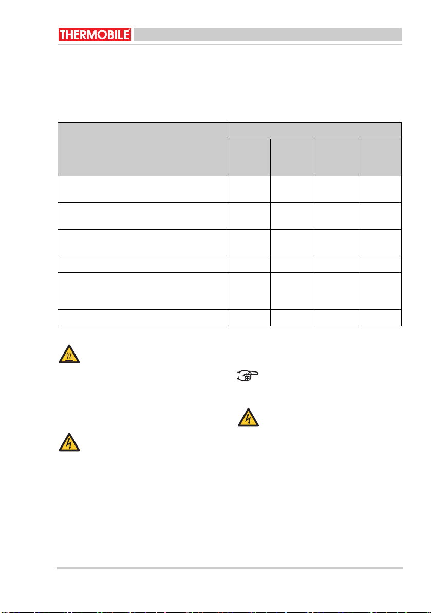
5 Техническое обслуживание
/i
5.1 Таблица техобслуживания
После каждого зимнего сезона
регистрируйте проведение техосмотра в
приложении в конце данного руководства.
Описание Период
Еженеде
льно
Ежемеся
чно
Каждые
шесть
Ежегодно
месяцев
Уда л и т е пыль и загрязнения с
X
воздухонагревателя.
Проверьте воздухонагреватель (в чистом
Дилер
месте).
Проверьте воздухонагреватель (в пыльном
Дилер
месте).
Проверьте и почистите входную решетку.X
Проверьте правильность
X
функционирования вентилятора,
проверьте наличие грязи и повреждений.
Проверьте электропроводку нагревателя.X
Горячо!
6 Неисправности
Не прикасайтесь к решетке
выходного отверстия!
Не начинайте техническое
обслуживание до тех пор, пока
решетка не остынет.
При поиске неисправности
проверьте, чтобы питание было
подключено.
ОСТОРОЖНО
5.2 Общие положения
ОСТОРОЖНО
Во время проведения технического
Во время проведения ремонта
извлекайте сетевую вилку из
розетки.
обслуживания извлекайте сетевую
вилку из розетки.
При долговременном хранении
нагревателя:
1. Выключите нагреватель.
2. Выньте контактную вилку из гнезда
питания.
3. Произведите чистку нагревателя.
BX3 / BX9 / BX15 40.020.959 - rev. 01 - 2007 47

6.1 Таблица поиска неисправностей
/i
Неисправность Причина Устранение Действие
Воздухонагревател
ь не работает.
1 Не подается
напряжение.
2 Дефект в панели
управления.
Проверьте подачу
электроэнергии.
Отремонтировать или
заменить панель
Пользова
тель
Дилер
управления.
3 Фаза - изменить
нулевые (ZERO)
Отремонтируйте
соединение.
Пользова
тель
провода в 5-полюсном
разъеме/ гнездовом
разъеме.
Вентилятор не
вращается, тепло
не выделяется.
4 Термостат установлен
на слишком низкую
температуру.
5 Плавкий
предохранитель в
системе неисправен.
Переустановите
термостат.
Замените плавкий
предохранитель.
(проверьте плотность
Пользова
тель
Пользова
тель
затяжки).
6 Двигатель
вентилятора
Замените двигатель
вентилятора.
Дилер
неисправен.
7 Пробит сетевой кабель
или кабель
Отремонтируйте
соединение.
Пользова
тель
удлинителя. (проводка
нарушена).
Положения 2 и 3:
Вентилятор
вращается
нормально, но
выделяется мало
тепла 50%.
8 Плавкий
предохранитель в
системе неисправен.
9 Неисправен сетевой
кабель или кабель
Замените плавкий
предохранитель.
(проверьте плотность
затяжки).
Отремонтируйте
соединение.
Пользова
тель
Пользова
тель
удлинителя.
10 Воздухонагреватель
функционирует при 2
Отремонтируйте
соединение.
Пользова
тель
фазах.
11 Один ослабленный
или сгоревший кабель
Отремонтируйте
соединение.
Пользова
тель
в вилке/гнезде кабеля
удлинителя.
48 40.020.959 - rev. 01 - 2007 BX3 / BX9 / BX15

Запишите подробности проведенного
обслуживания в таблицу в приложении A,
расположенного в конце данного
руководства .
7 Запасные части
По вопросам использования запасных
частей обратитесь к дилеру.
8 Техническая информация
• Тех нич еские характеристики
приведены в таблице В, которая
находится в приложении в конце
настоящего руководства.
• Электросхемы приведены в разделе С
в приложении к данному руководству.
8.1 Разъяснения электросхем.
/i
Поз. Описание
A Нагревательный элемент
B Мотор вентилятора
C Переключатель
D Управляющий термостат
E Защитный термостат
F Последовательное
сопротивление
9EС-Декларация соответствия
THERMOBILE INDUSTRIES B.V.,
Konijnenberg 80, NL-4825 BD BREDA с
полной ответственностью заявляет, что
изделия:
BX3 /BX9 / BX15 ЭЛЕК ТРИЧЕСКИЕ
ВОЗДУХОНАГРЕВАТЕЛИ
соответствуют следующим директивам
ЕС:
Нормативам по машиностроению: 98/37/
EEC
Нормативам по низкому напряжению: 72/
23/EEC
ЕМС-нормативам: 89/336/EEC
Голландия, г. Бреда,
01-10-2007
R.E. Merkenhof
Управляющий директор
BX3 / BX9 / BX15 40.020.959 - rev. 01 - 2007 49

/i
A
Datum Omschrijving: Onderhoud of Storing Actie door
Date Description: Maintenance or Failure Action by
Datum Beschreibung: Wartung oder Fehler Aktion durch
Date Description: Entretien ou Erreur Action par
Fecha Descripcíon Mantenimiento o fallo Accíon por
Дата Описание: устранение неисправности Выполнено
50 40.020.959 - rev. 01 - 2007 BX3 / BX9 / BX15

Datum Omschrijving: Onderhoud of Storing Actie door
Date Description: Maintenance or Failure Action by
Datum Beschreibung: Wartung oder Fehler Aktion durch
Date Description: Entretien ou Erreur Action par
Fecha Descripcíon Mantenimiento o fallo Accíon por
Дата Описание: устранение неисправности Выполнено
C: AGA 111
/i
BX3 / BX9 / BX15 40.020.959 - rev. 01 - 2007 51

B
Spanning
Voltage
Spannung
Tension
Tensión
Напряжение
Frequentie
Frequency
Frequenz
Fréquence
Frecuancia
Частота
Stroom max
Current max
Strom max
Courant max
Corriente max
Макс. сила тока
Capaciteit
Heat output
Wärmeleistung
Pouvoir thermique
Capacidad
Объем
Motorvermogen
Electric motor
Elektromotor
Moteur électrique
Motor eléctrico
Электродвигатель
Kabel
Cable
Kabel
Câble
Cable
Кабель
BX3 BX9 BX15
V / Fase
230 / 1 400 / 3 400 / 3
V / Phase
V / Phase
V / Phase
V / Fase
V / фаза
Hz 50 50 50
A 8,9 - 13,2 6,8 - 13,3 11,1 - 21,9
kcal/h 1720 / 2580 3870 / 7749 6450 / 12900
W327070
Aantal aders / mm
No. of cores / mm
Anzahl
Adressen / mm
Nombre de
2
fils / mm
Nº de hilos / mm
К-во жил / mm
2
3 / 2.5 4 / 2.5 4 / 4
2
2
2
2
52 40.020.959 - rev. 01 - 2007 BX3 / BX9 / BX15

Steker
Power plug
Stecker
Fiche d’alimentation
Enchufe eléctrico
Вилка сетевого кабеля
Luchtverplaatsing
Heated air flow
Heissluftleistung
Débit d’air chauffé
Flujo de aire calentado
Поток нагретого воздуха
Delta T
Delta T
Delta T
Delta T
T delta
Дельта Т
Geluid op 2 m afstand
Noise at a distance of 2 m
Schallpegel in
2 m Abstand
Niveau de bruit à 2 m de
distance
Ruido a una
distancia de 2 m
Уровень шума на
расстоянии 2 м
Omgevingstemp.
Ambient temperature
Umgebungs-temperatur
Température ambiante
Temperatura ambiente
Температура
окружающего воздуха
Breedte
Width
Breite
Largeur
Anchura
Ширина
BX3 BX9 BX15
CEE Euro 5P.16 5P.32
3
m
/h 220 700/900 1000
°C 38 36/28 42
dB(A) 444255
Max. °C 404040
mm 28 35 52
BX3 / BX9 / BX15 40.020.959 - rev. 01 - 2007 53

Lengte
mm 37 37 39
Length
Länge
Longeur
Longitud
Длина
Hoogte
mm 33 45 48
Height
Höhe
Hauteur
Altura
Высота
Gewicht
kg 6,5 11,5 15
Weight
Gewicht
Poids
Peso
Вес
Isolatieklasse
Insulation class
Isolationsklasse
Classe d’isolation
Clase de aislamiento
Класс изоляции
CE Ja
Zekering in zekeringkast
A162535
Fuse in cabinet
Sicherung in
Sicherungskasten
Fusible dans l'armoire
Fusible en armario
Предохранитель в Эл.
шкафу
/i
BX3 BX9 BX15
IP44 IP44 IP44
Ja
Yes
Ja
Oui
Sí
Да
Yes
Ja
Oui
Sí
Да
Ja
Yes
Ja
Oui
Sí
Да
54 40.020.959 - rev. 01 - 2007 BX3 / BX9 / BX15

MODEL Stand Verwarmings capaciteit kW A / aantal fasen
MODEL Position Heat output kW A / number of phases
MODELL Position Wärmeleistung kW A / Anzahl Phasen
MODÈLE Position Pouvoir thermique kW A / Nombre des
phases
MODELO Posición Capacidad kW A / Número de fases
МОДЕЛЬ Положен
ие
BX3 1 0 0.28 / 1
2 2 8,9 / 1
3 3 13.2 / 1
4 0 0.28 / 1
5 2 8,9 / 1
6 3 13.2 / 1
BX9 1 0 0.28 / 2
2 4,5 9 / 3
3 9 13.5 / 3
4 0 0.28 / 2
5 4,5 9 / 3
6 9 13.5 / 3
BX15 1 0 0.28 / 2
2 7,5 11,1 / 3
3 15 21,9 / 3
4 0 0.28 / 2
5 7,5 11,1 / 3
6 15 21,9 / 3
Объем kW A / количество фазах
BX3 / BX9 / BX15 40.020.959 - rev. 01 - 2007 55

C: (BX3: 230 V / 50 Hz)
A
B
M
11a22a33a44a55a66a77a8
C
D
E
8a
1
2
3
4
5
6
7
8
230V~
56 40.020.959 - rev. 01 - 2007 BX3 / BX9 / BX15

C: (BX9: 400 V / 3 Ph / 50 Hz)
A
B
M
9a
1
2
3
4
5
6
7
8
9
2
1
C
1a
D
E
33a44a55a66a77a88a9
2a
F
313211
12
L1L2L
3
400V3~
BX3 / BX9 / BX15 40.020.959 - rev. 01 - 2007 57

C: (BX15: 400 V / 3 Ph / 50 Hz)
A
3111 21 41
D
B
M
3212 22 42
2134
C
2a1a 3a 4a 5a 6a 7a 8a 9a
E
L1L2L
400V3~
56789
F
3
1
2
3
4
5
6
7
8
9
58 40.020.959 - rev. 01 - 2007 BX3 / BX9 / BX15

© 2007 Thermobile Industries B.V.
Alle rechten voorbehouden. De verstrekte informatie mag niet worden verveelvoudigd en/of
openbaar gemaakt op welke wijze dan ook (elektronisch of mechanisch), zonder schriftelijke
toestemming van Thermobile Industries B.V. Thermobile Industries B.V. kan niet aansprakelijk
worden gesteld voor schade die voortkomt of verband houdt met afwijkingen in deze
handleiding.
© 2007 Thermobile Industries B.V.
All rights reserved. The available information has been prepared to a high level of care, but
Thermobile Industries B.V. cannot be held liable for possible errors in the information or the
consequences thereof. The information provided herein may not be reproduced and/or
published in any form, by print, (electronically or mechanically) without the prior written
authorisation of Thermobile Industries B.V.
© 2007 Thermobile Industries B.V.
Alle Rechte vorbehalten. Die verfügbare Information wurde mit großer Sorgfalt vorbereitet.
Thermobile Industries B.V. kann jedoch für eventuelle Fehler in der Information oder den
Konsequenzen daraus nicht haftbar gemacht werden. Die gelieferte Information darf ohne die
vorherige schriftliche Genehmigung von Thermobile Industries B.V. weder reproduziert, noch in
irgendeiner Weise durch Drucken (elektronisch oder mechanisch) veröffentlicht werden.
© 2007 Thermobile Industries B.V.
Tous les droits réservés. L’ensemble des informations disponibles a été préparé avec un soin
extrême. Cependant, Thermobile Industries B.V. décline toute responsabilité à l’égard des
erreurs possibles ou de leurs conséquences. Les informations fournies ici ne peuvent être
reproduites ou publiées sous quelque forme que ce soit, voire imprimées (électroniquement ou
mécaniquement) sans l’autorisation écrite préalable de Thermobile Industries B.V.
© 2007 Thermobile Industries B.V.
Todos los derechos reservados. La información disponible se ha preparado con sumo cuidado
pero, en caso de errores en dicha información, Thermobile Industries B.V. no será considerada
responsable de los mismos ni de las consecuencias derivadas de éstos. La información aquí
contenida no puede ser reproducida ni publicada en forma alguna, mediante impresión
(electrónica o mecánica) sin la previa autorización por escrito de Thermobile Industries B.V.
© 2007 Thermobile Industries B.V.
Воспроизводство и издание информации из данного руководства каким бы то ни было
способом: перепечаткой, фотопечатью, микрофильмом или любыми другими средствами
Thermobile Industries B.V. (электронными или механическими
письменного разрешения компании Thermobile Industries B.V. запрещено.
) без предварительного
motralec
4 rue Lavoisier . ZA Lavoisier . 95223 HERBLAY CEDEX
Tel. : 01.39.97.65.10 / Fax. : 01.39.97.68.48
Demande de prix / e-mail : service-commercial@motralec.com
www.motralec.com
BX3 / BX9 / BX15 40.020.959 - rev. 01 - 2007 59
 Loading...