

THERMOBILE Bio Energy Series, Bio Energy 2 User Manual

40.020.953 - rev. 05 - 2015
/i
A
B
C
E
D
F
G
H
THERMOBILE
Type.......................................................
Cap Max. Mj/h........................................
Cap Max. kW.........................................
3
Airflow m
/h...........................................
Volt/Hz/Amp...........................................
Prod. code.............................................
Fabr.year 0000 Serial nr: 00.0000
Made by THERMOBILE Ind. B.V. Breda, Holland
- 1 - - 2 -
A B C DEF
R Q P O N M L K J
S
- 3 - - 4 -
AT400/500
A
AT-400
000
00
0
000/00/0,00
00.000.000
G H I
D
C
B
E
B
C
A
A
B
J
C
D
E
F
G
H
I
- 5 -
2
40.020.953 - rev.
05 - 2015
Bio Energy series
/i
B
A
C
D
A
- 6 - - 7 -
ABCDEF
- 8- - 09 -
B
C
B A
C
B
A
- 10 - - 11 -
Bio Energy series
40.020.953 - rev.
05 - 2015
D
C
B
A
3

Nederlands ..................................................5
English.......................................................17
Deutsch......................................................29
Français.....................................................43
Español......................................................56
Русский язык.............................................70
4
40.020.953 - rev. 05 - 2015
Bio Energy series

Nederlands
All
Inhoud
Veiligheidsinstructies................................... 6
Introductie ................................................... 6
Voorbereidingen.......................................... 8
Gebruik ....................................................... 9
Onderhoud .................................................. 9
Storingen................................................... 13
Reserveonderdelen................................... 15
Technische informatie ............................... 15
Installatie van accessoires ........................ 15
EG-Verklaring van overeenstemming ....... 16
Nederlands
Milieu
Let op
De kachel is gemaakt van diverse
metalen en kunststoffen. De kachel
bevat tevens elektronische
onderdelen, die als elektronisch afval
moeten worden behandeld. Neem
contact op met uw dealer voor
nadere informatie.
een van toepassing in de
Europese Unie
Voorwoord
Deze handleiding bevat de
gebruiksaanwijzing voor de op de kaft
vermelde kachels. De informatie in deze
handleiding is belangrijk voor een juist en
veilig gebruik van de kachel.
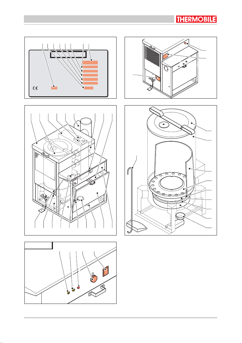
Identificatie van het product (fig. 1)
Het identificatieplaatje is bevestigd op de
zijkant van de kachel. Het identificatieplaatje
bevat de volgende gegevens:
A Jaar van fabricage
B Serie nummer
C Productie code
D Spanningsgegevens
E Luchtverplaatsing
F Capaciteit max (kW)
G Capaciteit max (Mj/h)
H Type kachel
Service en technische ondersteuning
Neem voor informatie over de kachel contact
op met uw dealer of met de fabrikant. Zorg
dat u de volgende gegevens bij de hand hebt:
type en serie nummer van de kachel.
Garantie en aansprakelijkheid
Voor garantie en aansprakelijkheid, zie
algemene garantiebepalingen.
Afvalverwijdering van elektrische
& elektronische apparatuur voor
zakelijk gebruik.
Voor nadere informatie aangaande
het wegwerpen van producten voor
zakelijke doeleinden aan het einde
van hun levensduur, wordt u verzocht
contact op te nemen met uw dealer
of distributeur in uw land. Dit product
mag niet samen met of in de vorm
van commercieel afval worden
weggegooid.
Bio Energy series
40.020.953 - rev. 05 - 2015
5
Nederlands
1 VEILIGHEIDSINSTRUCTIES
1.1 Pictogrammen in deze handleiding
VOORZICHTIG
Wijst op gevaar voor beschadiging
van de apparatuur.
WAARSCHUWING
Wijst op een gevaarlijke situatie, die
de dood of ernstige verwondingen tot
gevolg kan hebben.
WAARSCHUWING
Schakel bij onderhouds- of
reparatiewerkzaamheden aan de
kachel altijd de elektrische stroom uit!
Heet
Sommige vlakken kunnen heet zijn!
Wacht met onderhoud totdat deze
onderdelen voldoende zijn afgekoeld.
Suggesties en tips om de uitvoering
van de betreffende taken of
handelingen te vereenvoudigen.
1.2 Pictogrammen op de stationaire
plantaardige olie of biodiesel
gestookte kachel (fig. 2)
A Waarschuwing voor de hoeveelheid te
gebruiken olie.
Instructie om de branderschaal niet op
een koud oppervlak te plaatsen.
B Oververhittingsthermostaat.
C Instructie voor opnieuw ontsteken.
D Standen van de brander: laag en hoog.
1.3 Gebruik dit product waarvoor het
bestemd is
De stationaire plantaardige olie of biodiesel
gestookte kachel is ontworpen voor
verwarming van werkplaatsen bij
mechanisatiebedrijven, verwarmen en
vorstvrij houden van hallen, opslagloodsen
en magazijnen en voor de verwarming van
garagewerkplaatsen en magazijnen.
1.4 Algemene instructies
Waarschuwing
• Lees deze handleiding zorg-
vuldig door, alvorens de kachel
te gebruiken.
• Bewaar dit document bij de
kachel.
• Volg de beschreven procedures.
• Leun nooit op de kachel.
• Zorg dat er licht ontvlam
materiaal op voldoende afstand
van de kachel b
- bovenzijde en zijkanten
150 mm
- voorkant 900 mm
- achterkant en schoorsteen
450 mm
• Zet de kachel niet op ee
brandbare vloer.
• Zorg dat er voldoende lucht is
voor een goede verbranding.
• Voer uitsluitend reparatie- en
onderhoudswerkzaamheden uit
als de kachel voldoende is
afgekoeld, en nadat de stekker
uit de contactdoos is verwijderd.
2 INTRODUCTIE
2.1 Doel
Deze stationaire plantaardige olie of biodiesel
gestookte kachels hebben een thermische
beveiliging, warmtewisselaar, verbrandingsluchtventilator, schoorsteenaansluiting met Tstuk en regelklep voor de trek en een warmeluchtventilator.
De kachels zijn getest op zeeniveau bij een
temperatuur van 20 °C.
2.2 Werkingsprincipe
De stationaire plantaardige olie of biodiesel
gestookte kachel is uitgevoerd met drie
elektromotoren.
baar
lijft:
n
6
40.020.953 - rev. 05 - 2015
Bio Energy series

Nederlands
De eerste elektromotor drijft een brandstofpomp aan, die de brandstof uit de brandstoftank trekt.
De tweede elektromotor drijft de verbrandingsluchtventilator aan, die de verbrandingslucht in de verbrandingskamer blaast.
De derde elektromotor drijft de warmeluchtventilator aan, die de omgevingslucht om de
verbrandingskamer en de warmtewisselaar
blaast. De lucht wordt verwarmd en in de te
verwarmen ruimte geblazen.
Op een branderschaal wordt handmatig
plantaardige olie of biodiesel gegoten, die
met een brandende papierprop wordt ontstoken. Zodra de branderschaal op temperatuur is, schakelt een thermostaat de brandstofpomp in; de controlamp gaat branden. De
brandstofpomp pompt de plantaardige olie of
biodiesel op de branderschaal. De plantaardige olie of biodiesel verdampt door de temperatuur van de branderschaal. De gevormde gasdamp verbrandt. Een thermostaat
schakelt de motor van de warmeluchtventilator in om de warme lucht in de te verwarmen omgeving te blazen.
De maximaalthermostaat schakelt de brandstofpomp uit als de kachel te heet wordt.
De brandstofpomp wordt uitgeschakeld als
de kachel wordt uitgeschakeld.
De warmeluchtventilator draait tot de verbrandingsluchtthermostaat de ventilator uitschakelt: hierdoor wordt de kachel gekoeld.
De maximaal thermostaat schakelt de kachel
uit als de temperatuur te hoog wordt.
De brandstoftoevoer heeft een overloop
waardoor bij een verstopte brandstofleiding
de plantaardige olie of biodiesel terugvloeit in
de brandstoftank.
Een overloopbeveiliging schakelt de
brandstofpomp uit als de branderschaal
overloopt.
2.3 Hoofdcomponenten stationaire
plantaardige olie of biodiesel
gestookte kachel (fig. 3)
ADeksel
B Branderkamer
C Warmtewisselaar
D Maximaal thermostaat
E Thermostaten
F T-stuk met trekregelaar
G Warmeluchtventilator
H Verbrandingsluchtventilator
I Vulfilter
J Bedieningspaneel
K Brandstoftank
L Aftapkraan
M Brandstoffilter
N Brandstofpomp
O Identificatieplaatje
P Retourleiding
Q Schuiflade
R Brandstofopvoerpijp
S Brandstoftoevoerpijp
2.4 Hoofdcomponenten brander (fig.
4)
A Deksel verbrandingskamer
B Branderkamer
C Vlamkeerschot
D Branderring
E Afdichtkoord
F Branderschaal
G Verdamper
H Bodem branderkamer
I Overloopbeveiliging
J Schep
2.5
Bedieningspaneel (fig. 5)
A Controlelamp geel
B Controlelamp geel
C Controlelamp rood
D Grendel brandstoftank
E Wipschakelaar:
- 0: De pomp is uitgeschakeld
- 1: Lage pompsnelheid
- 2: Hoge pompsnelheid
2.6 Thermostaat
De kachel heeft de volgende thermostaten:
• Pompthermostaat:
Als de verbrandingssch
voorverwarmd is, start de brandstofpomp
op.
• Warmeluchtthermostaat:
De thermostaat st
warmeluchtventilator als de kachel een
bepaalde temperatuur heeft bereikt.
aal voldoende
art de
Bio Energy series
40.020.953 - rev. 05 - 2015
7
Nederlands
• Maximaal thermostaat:
De thermostaat stopt de brandstofpomp
als de warmeluchttemperatuur te hoog
wordt.
2.7 Accessoires
• Schoorsteen met regenkap
3 VOORBEREIDINGEN
3.1 Verpakking verwijderen
1. Verwijder de verpakking van de kachel.
2. Verwijder de delen die los in
de
verbrandingskamer liggen.
3. Verwijder de verpakking van de delen die
los in de verbrandingskamer liggen.
3.2 Installatie
1. Zorg ervoor dat de kachel horizont
aal
staat.
2. Breng de ond
erdelen van de
verbrandingskamer op de juiste wijze
aan, zie fig. 4.
3. Monteer de veschillende handgrepen
aan het deksel en de schuif, zie fig. 3.
Schuif de tankgrendel omhoog, zie fig. 6
4.
(C).
5. Trek de brandstoftank naar voren.
6. Vul de brandstoftank altijd door
het
tankfilter met plantaardige olie of
biodiesel, tot het niveau 25 mm beneden
de bovenkant van de tank wordt bereikt.
VOORZICHTIG
In de stationaire plantaardige olie of
biodiesel gestookte kachels mogen
alleen de volgende oliesoorten
verbrand worden:
• Plantaardige olie
• Biodiesel
7. Sluit de brandstoftank: zorg dat deze
vergrendeld is.
8. Zorg ervoor dat de verwar
mde lucht
ongehinderd kan worden uitgeblazen.
9. Zorg dat brandbare stoffen voldoende ver
van de kachel verwijderd zijn, zie 1.4.
10. Zorg voor voldoende ventilatie: het
maximale luchtverbruik voor verbranding
3
75 m
is
/uur.
11. Controleer de vloeroppervlakte: deze
moet minimaal 60 m
2
bedragen.
12. Installeer de schoorsteen (5.5 m en een
regenkap).
13. Zorg ervoor dat de wipschakelaar in de
stand 0 staat.
14. Controleer de voedingsspanning
: zie het
identificatieplaatje.
15. Steek de steker in de contactdoos.
3.3 Voorbereiden voor opstarten
1.
Zet de wipschakelaar in stand “0”.
Zet de knop wips
2.
chakelaar van de
brandstofpomp in de stand “1”, zie (fig.5).
3. Tap eventueel condenswater af uit de
brandstoftank, zie fig. 3 (L).
4.
Open de schuiflade: druk het pedaal (A)
omlaag en ho
veiligheid
ud het ingedrukt, licht de
(B) op, draai de knop (C) linksof rechtsom en laat het pedaal los, zie
fig. 6 Trek de schuiflade (D) naar voren.
5. Controleer of de branderschaal en de
bodem van de verbrandingskamer
schoon en afgekoeld zijn.
6. Maak de br
anderschaal en de bodem
van de verbrandingskamer eventueel
schoon.
7. Giet 0.3 liter plantaardige olie of biodiesel
op de branderschaal, zie fig. 4 (F).
WAARSCHUWING
Giet nooit plantaardige olie of
biodiesel op een warme
branderschaal.
De branderschaal moet afgekoeld
zijn!
8. Maak een prop papier en steek deze aan.
9. Leg de brandende prop op de
branderschaal.
10. Schuif het schuifpaneel dicht.
11. Controleer door het bovendeksel of er
geen vlam is rond het afdichtkoord en
tussen de bodem en de
verbrandingskamer, zie fig. 4.
8
40.020.953 - rev. 05 - 2015
Bio Energy series
Nederlands
3.4 Opstarten
Zet de wipschakelaar in stand “1”, zie fig.
1.
5(E).
Als de branderschaal de juiste
temperatuur heef
brandstofpomp
t bereikt, begint de
te draaien en de
controlelamp brandt.
2. Gedurende de eerste 20 - 30 minuten
moet de brandstofpomp een lage
opbrengst hebben.
De gele controlelamp brandt, zie fig. 5
(A).
3.
Zet de wipschakelaar in de stand “2”,
(voor hoge opbrengst) zie fig. 5(E). De
rode cont
rolelamp brandt, zie fig. 5 (C).
4 GEBRUIK
4.1 Tijdens bedrijf
Heet
Raak de schoorsteen en
uitblaasopening niet aan! De
schoorsteen en de uitblaasopening
worden heet tijdens bedrijf!
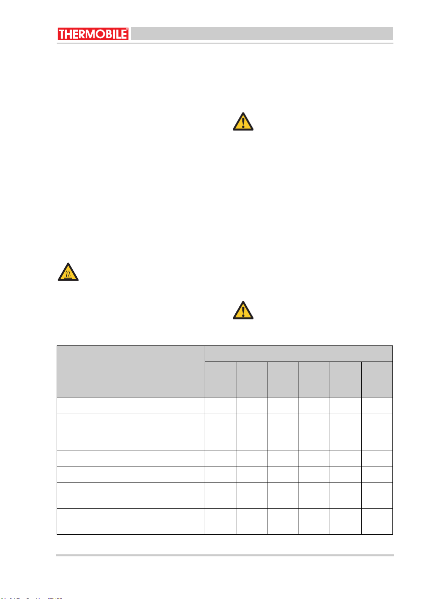
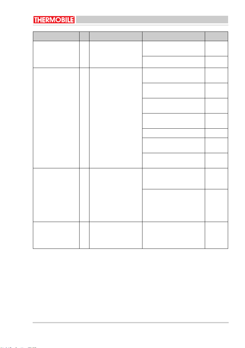
Beschrijving Periode
Elke
12 uur
Reinig de branderschaal. X
Tap condens(water) af van de brandstoftank, als de plantaardige olie of biodiesel
water bevat.
Reinig de branderkamer. X
Reinig de branderring. X
Reinig de binnenzijde van de branderka-
X
mer en verdamper met een staalborstel.
Reinig de gaten in de bodem van de ver-
X
damper met een staalborstel.
4.2 Uitschakelen
Uitschakelen van verwarming:
1. Zet de wipschakelaar in de “0” stand.
De brandstofpomp stopt.
De controlamp gaat uit.
VOORZICHTIG
Na het uitschakelen blijft de kachel
nog enkele minuten branden, totdat
de brandstof op de branderschaal
opgebuikt is. Ondertussen blijven de
warmeluchtventilator en de
verwarmingsluchtventilator draaien.
Deze ventilatoren koelen de kachel
tot deze voldoende is afgekoeld (na
10 tot 30 minuten).
De beide ventilatoren zullen
ongeveer gelijktijdig stoppen.
5 ONDERHOUD
5.1 Onderhoudstabel
Registreer na elk winterseizoen het
onderhoud in de tabel achterin dit boek.
WAARSCHUWING
Reinig de branderschaal altijd voor
het opstarten van de kachel.
/i
Iedere
week
Iedere
maand
Ieder
half
jaar
Ieder
jaar
Iedere
twee
jaar
X
Bio Energy series
40.020.953 - rev. 05 - 2015
9
Nederlands
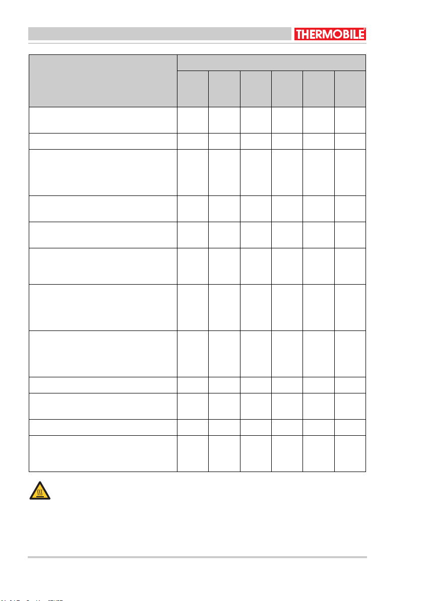
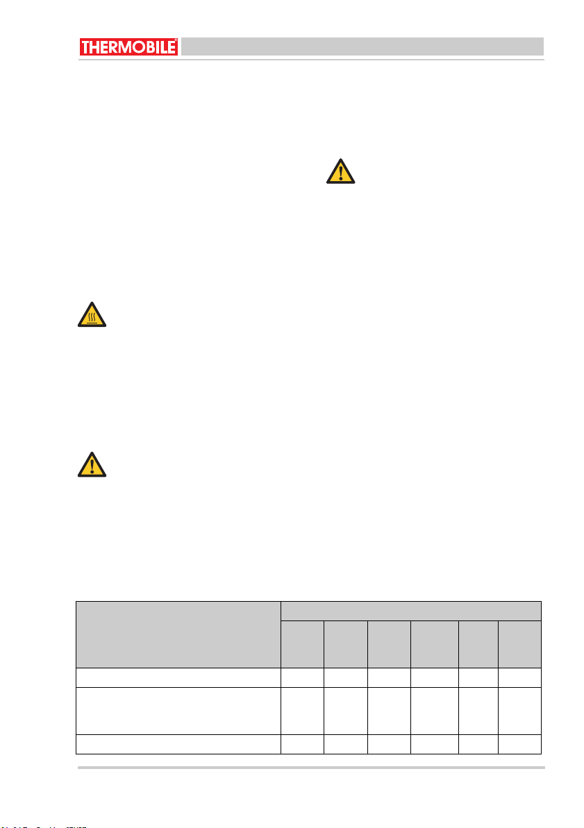
Beschrijving Periode
Elke
12 uur
Reinig de olieoverlooppijp in de bodem
van de verbrandingskamer, zie fig. 4 (I)
Controleer de olieleidingen op lekkage. X
Reinig de brandstoftank, het toevoerfilter
en het brandstoffilter.
De brandstoftank kan eenvoudig verwijderd worden.
Controleer de verbrandingsluchtventilator en reinig deze, indien nodig.
Controleer de warmeluchtventilator en
reinig deze, indien nodig.
Reinig de schoorsteenklep in het T-stuk,
zie fig. 8 (A).
De aanbevolen trek is 2 mmwk.
Controleer de afdichting tussen bodem
en de verdamper op lekkage.
Stel de druk op het afdichtkoord af, of
vervang de afdichting.
Vervang het afdichtkoord in de bodem.
Controleer de afdichtring op lekkage.
Stel de druk op het afdichtkoord af bij
lekkage.
Reinig de warmtewisselaar. X
Reinig het T-stuk van de schoorsteen,
zie “schoor-steenklep reinigen”.
Controleer de bedrading van de kachel. X
Reinig de warmtewisselaar.
Bouw de warmtewisselaar uit voor een
goede reiniging.
Iedere
week
Iedere
maand
X
Dealer
X
Ieder
half
jaar
X
X
X
X
Ieder
jaar
X
X
Iedere
twee
jaar
Heet
Raak de schoorsteen en de
branderkamer niet aan!
Wacht met onderhoud totdat de
schoorsteen en de branderkamer zijn
afgekoeld.
10
40.020.953 - rev. 05 - 2015
Bio Energy series
Nederlands
5.2 Algemeen
WAARSCHUWING
Sluit de elektrische stroom uit tijdens
onderhoud.
Als de kachel voor langere tijd opgeslagen
wordt:
1. Schakel de kachel uit.
2. Neem de elektrische aansluiting los.
3. Reinig de kachel.
4. Reinig de verbrandingskamer met
doek met olie, om de verbrandingskamer
te beschermen tegen corrosie.
WAARSCHUWING
Laat de kachel bij warm weer niet
branden om nutteloos olie te
verbranden.
5.3 Reinigen verbrandingskamer (fig.
4)
1. Open het deksel van de
verbrandingskamer, zie fig. 4 (A).
2. Verwijder de branderring (D) met de haak
van de schep (J).
3. Reinig de branderring met e
staalborstel.
4. Verwijder de branderschaal (F) met de
haak van de schep.
5. Reinig de branderschaal met een
schraper.
6. Reinig de binnenkant van de
branderkamer (B) en de verdamper (G)
met de voorkant van de schep.
Zorg dat de gaten in de verdamper
open zijn voor de toevoer van
verbrandingslucht.
7. Verwijder eventuele roetdeeltjes van de
bodem van de branderkamer.
8. Reinig
9. Reinig de brandstoftoevoerleiding (N)
10. Breng alle delen in de omgekeerde
het overlooppijpje in de
verdamper inwendig met een kleine
borstel (diameter 4 mm).
met een borstel (binnendiameter 8.5 mm
3”), zie fig. 3.
(0.3
volgorde aan.
een
en
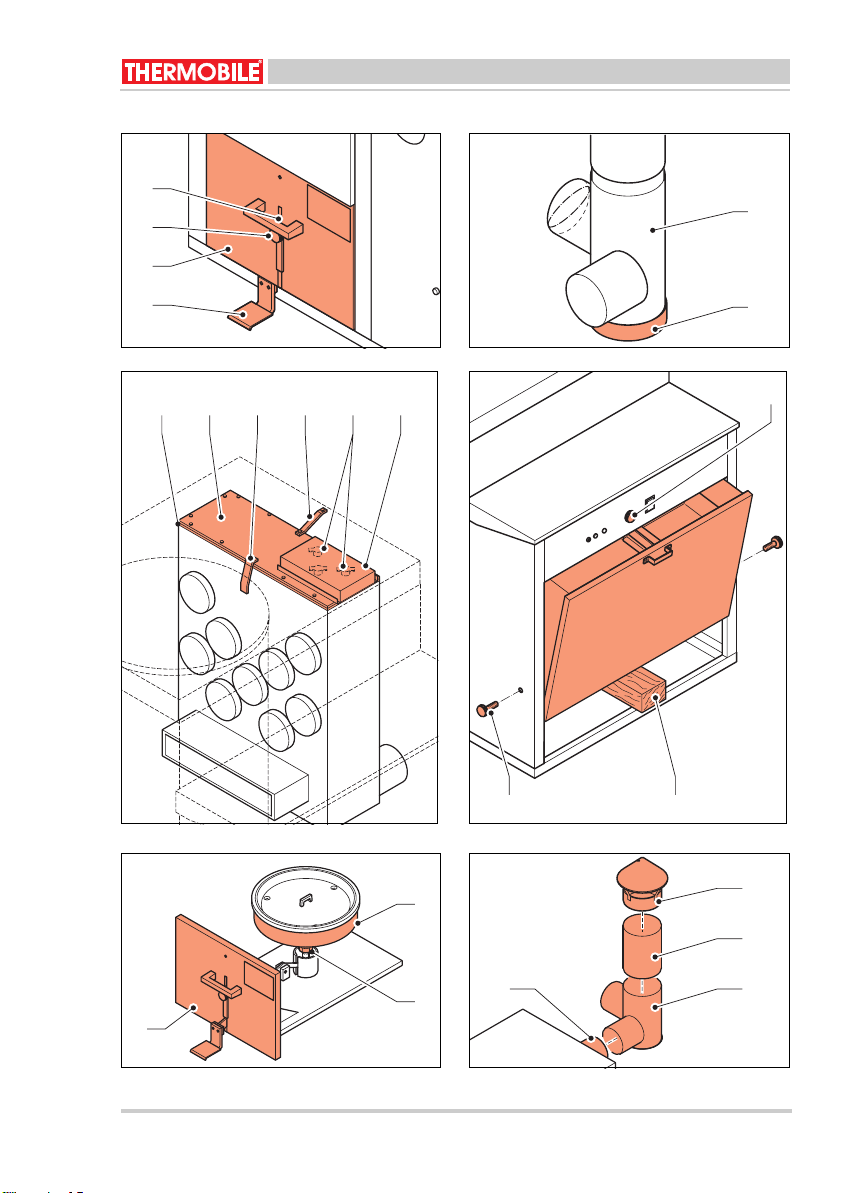
5.4 Reinigen warmtewisselaar (fig. 9)
1.
Neem de elektrische aansluiting van de
kachel los.
2. Open het deksel, zie fig. 3 (A).
3. Schroef de thermostaat beugel (A) los.
4. Neem de bedrading van beide
thermostaten (B) los.
5. Verwijder bevestigingsstrip (C).
6. Verwijder bevestigingsstrip (D).
7. Verwijder het deksel (E) van
warmtewisselaar.
8. Reinig de binnenkant van de
warmtewisselaar met een borstel en e
stofzuiger.
9. Breng het deksel weer aan op de
warmtewisselaar.
Breng altijd een nieuwe pakking (F)
aan tussen het deksel en de
warmtewisselaar.
Breng alle delen in de omgekeerde volgorde
aan.
Breng de bedrading van de
thermostaten aan volgens het
elektrisch schema. Beide
thermostaten zijn gelijk.
5.5 Uitbouwen warmtewisselaar (fig.
9)
Neem de elektrische aansluiting van de
1.
kachel los.
Verwijder het T-stuk (A) van de
2.
schoorsteen, zie fig. 3 (F).
3. Verwijder het deksel, zie fig. 3 (A).
4. Schroef de thermostaat beugel (A) los.
5. Neem de bedrading van beide
thermostaten (B) los.
6. Verwijder bevestigingsstrip (C).
7. Verwijder bevestigingsstrip (D).
8. Verwijder de brandstofopvoerpijp, zie fig.
3 (S).
9. Schroef de steun van de overloopbeker
los en leg overloopbeveiliging op de
bodem van de kach
10. Verwijder de verbrandingsluchtv
(H) met motorsteun, zie fig. 3.
de
en
el.
entilator
Bio Energy series
40.020.953 - rev. 05 - 2015
11

Nederlands
11. Schroef het achterpaneel van de kachel
los en draai het 180° naar de
brandstoftank.
Ondersteun het achterpaneel tijdelijk in
deze stand.
12. Verwijder het huis van de
verbrandingsluchtventilator.
WAARSCHUWING
Verander de instelling van de klep
in dit huis niet.
13. Schroef het frame van de branderkamer
los van de grondplaat van de kachel.
14. Til de branderkamer met de
warmtewisselaar uit de kachel.
Doe dit met twee personen.
15. Schroef de verbinding van de
branderkamer en de warmtewisselaar
los.
16. Verwijder de strip tussen de
branderkamer en de warmtewissleaar.
17. Trek de warmtewisselaar van de
branderkamer.
18. Verwijder boven- en onderdeksel van de
warmtewisselaar.
19. Reinig de warmtewisselaar inwendig met
een borstel en verwijder vuil met een
stofzuiger.
20. Breng het boven- en onderdeksel weer
aan op de warmtewisselaar.
Breng altijd een nieuwe pakkingen
aan tussen het boven- en
onderdeksel en de warmtewisselaar.
Bouw de kachel in de omgekeerde volgorde
op.
Breng de bedrading van de
thermostaten aan volgens het
elektrisch schema. Beide
thermostaten zijn gelijk.
5.6 Reinigen schoorsteen (fig. 8)
1. Verwijder het bodemdeksel (B) van het Tstuk (A).
2. Reinig de schoo
onder met een draadster.
3. Controleer de aansluitingen op lekkage.
4. Controleer de schoorsteendelen op
roest.
VOORZICHTIG
Roest geeft aan dat er
chloorhoudende materialen verbrand
zijn.
Chloorhoudende materialen
beschadigen de kachel ernstig.
Hierdoor vervalt de garantie.
Neem contact op met uw dealer voor
instructies om de plantaardige olie of
biodiesel op chloor te testen.
Breng het bodemdeksel weer aan.
5.7 Wegnemen brandstoftank (fig. 10)
1. Tap de brandstoftank af via de aftap, zie
fig. 3 (L).
2. Schuif de tankgrendel omhoog, zie fig. 10
(C).
3. Ondersteun de brandstoftank me
houten klos (A).
4. Verwijder de zwarte kartelbout (B) aan de
linker en rechter zijde van de
brandstoftank.
5. Verwijder de brandstoftank met be
handen door de tank aan de onderzijde
vast te pakken.
6. Verwijder de houten klos.
7. Laat de brandstoftank voorzichtig zakken
en draai de brandstoftank uit de kachel.
Verwijder de brandstoftank
voorzichtig: het brandstofsysteem is
in de brandstoftank aangebracht.
Installeer de brandstoftank in de omgekeerde
volgorde.
5.8 Afstellen druk afdichtingskoord
(fig. 11)
1. Open het schuifpaneel (A), zie 3.3.
2. Draai de moer (B) los.
rsteen van boven tot
t een
ide
12
40.020.953 - rev. 05 - 2015
Bio Energy series
Nederlands
3. Draai de bodem (C) van de verdamper
6STORINGEN
iets omhoog of omlaag (afhankelijk van
de situatie).
4. Draai de moer (B) aan.
5. Schuif het schuifpaneel in de kachel.
Controleer of het afdichtkoord goed
afdicht als de kachel brandt.
Zorg dat de stroom is ingeschakeld
en de brandstoftank vol is, voordat u
begint met storingzoeken.
WAARSCHUWING
Sluit de elektrische stroom af tijdens
reparatie!
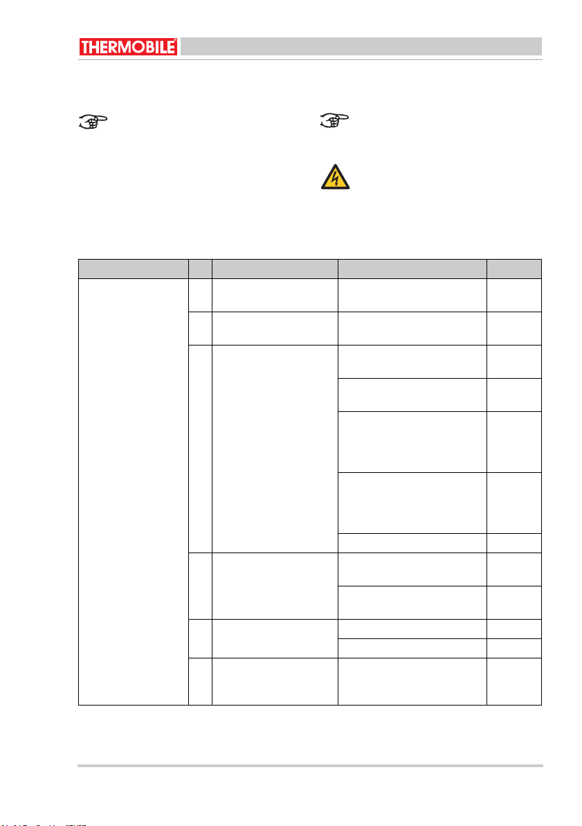
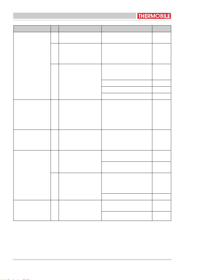
6.1 Tabel storingzoeken
/i
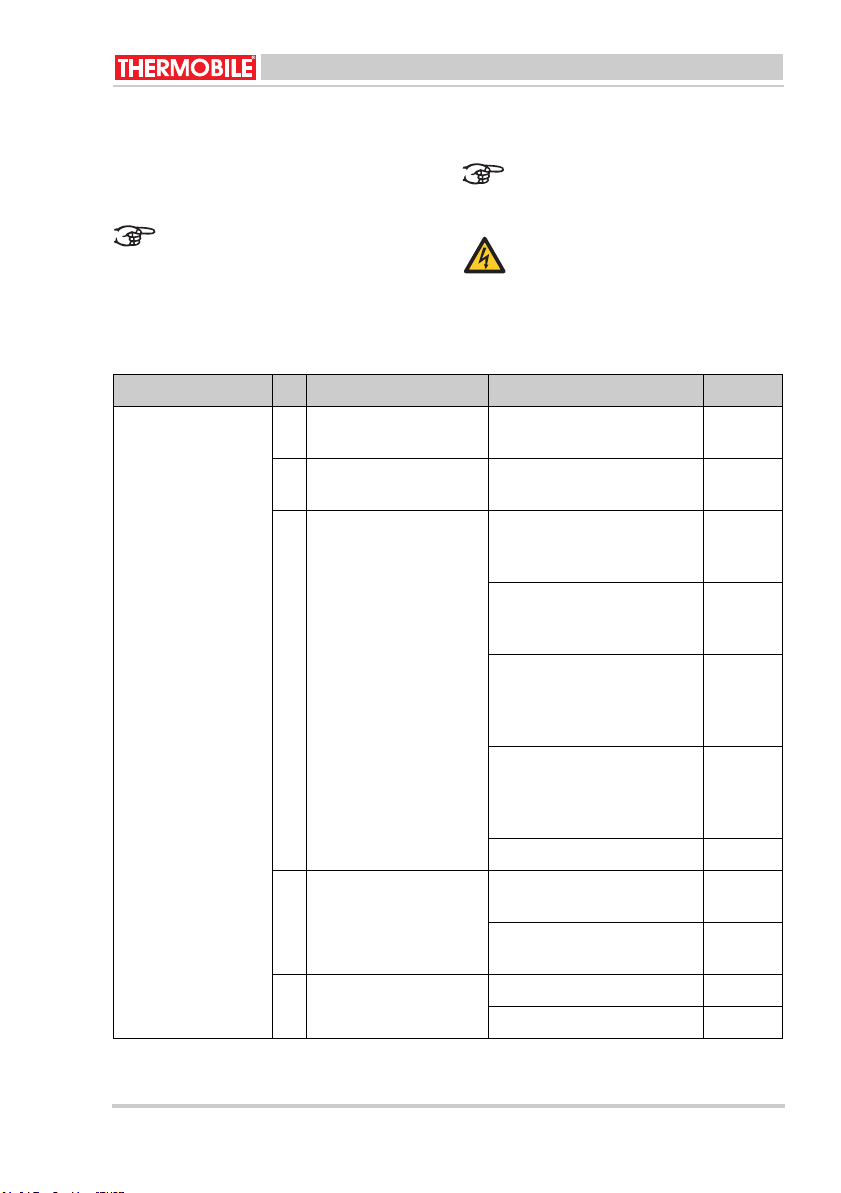
Storing Oorzaak Oplossing Actie
De vlam dooft direct
na het aansteken; de
controlelamp brandt
niet.
1 De kachel heeft geen
spanning.
2 De brandstofpomp is
niet ingeschakeld.
3 De motor en de pomp
werken niet.
Controleer de elektrische
aansluiting.
Zet de schakelaar in stand
“1”, zie fig. 5 (A).
Verwarm de brandstof (maxi-
0
maal 50
C) of verdun deze
Gebruiker
Gebruiker
Gebruiker
met biodiesel.
Controleer de pompthermos-
Dealer
taat en vervang deze, indien
nodig.
Controleer de overloopbe-
Gebruiker
veiligingsschakelaar door de
overloopkom een paar keer
op en neer te bewegen.
Controleer of de pompas
Gebruiker
handmatig gedraaid kan worden. Reinig de pomp als dit
niet kan.
Controleer de pompmotor. Dealer
4 De pompthermostaat
heeft de volledige temperatuur nog niet
bereikt.
5 De maximaal thermos-
taat is defect.
Laat de kachel afkoelen.
Gebruiker
Start de kachel opnieuw op.
Vervang de pompthermos-
Dealer
taat.
Reset de thermostaat. Gebruiker
Vervang de thermostaat. Gebruiker
Bio Energy series
40.020.953 - rev. 05 - 2015
13

Nederlands
Storing Oorzaak Oplossing Actie
De vlam dooft direct
na het aansteken; de
controlelamp brandt
niet.
De vlam dooft direct
na het aansteken; de
controlelamp brandt .
De verbrandingsluchtventilator blijft
draaien, terwijl de
warmeluchtventilator
gestopt is en de
kachel is afgekoeld.
Er is roetvorming in
de verbrandingskamer en in de
schoorsteen.
6 De overloopbeveiliging
is vol met plantaardige
olie of biodiesel.
7 Er is water of bezinksel
in de brandstoftank.
8 De brandstoftoevoerpijp
is verstopt: de brandstof
stroomt terug in de
brandstoftank via de
retourleiding.
9 De trek in de schoor-
steen in niet goed.
10 De verbrandingsther-
mostaat is defect.
11 De verbrandingslucht-
ventilator werkt niet.
12 Er is onvoldoende toe-
voer van verbrandingslucht.
13 De schoorsteen heeft
een te grote of onregelmatige trek.
Reinig de overloop kom,
branderschaal en bodem van
de verdamper.
Reinig de brandstoftank en
het brandstoffilter, zie fig. 3.
Reinig de brandstoftoevoerpijp, of vervang deze indien
nodig.
Controleer of de schoorsteen
aangebracht is volgens
opgave, zie “schoorsteen”.
Controleer de schoorsteen
op lekkage.
Reinig de schoorsteen, indien nodig.
Zie storingen: 3 en 4.
Vervang de verbrandingsthermostaat.
Controleer de motor en vervang deze, indien nodig.
Reinig de gaten in de verdamper.
Controleer de werking van de
verbrandingsluchtventilator.
Breng een schoorsteenklep
aan, zie “schoorsteen”.
Stel de schoorsteen af op de
juiste druk, zie § 5.3.
Zie storingen: 9, 12 en 13.
Gebruiker
Gebruiker
Gebruiker
Gebruiker
Gebruiker
Gebruiker
Gebruiker
Dealer
Gebruiker
Gebruiker
Dealer
14
40.020.953 - rev. 05 - 2015
Bio Energy series
Nederlands
Storing Oorzaak Oplossing Actie
Er is lekkage tussen
de bodem op het
schuifpaneel en de
verdamper.
De vlam dooft direct
na het aansteken.
De kachel maakt een
brommend geluid.
Er is onverbrande
plantaardige olie of
biodiesel op de branderschaal.
14 Er is lekkage tussen de
bodem op het schuifpaneel en de verdamper.
15 De trek in de schoor-
steen is te laag.
16 Er is te veel plantaar-
dige olie of biodiesel bij
het opstarten.
Stel de druk in op het afdichtkoord.
Vervang het afdichtkoord. Gebruiker
Controleer alle verbindingen
in de schoorsteen.
Controleer of de trekafstelling dicht staat.
Controleer de schoorsteen
op verstopping.
Verminder het aantal bochten.
Verhoog de schoorsteen. Gebruiker
Isoleer de schoorsteen buiten het gebouw.
Controleer de schoorsteen,
zie “schoorsteen”.
Verminder bij een nieuwe
start de hoeveelheid plantaardige olie of biodiesel.
Lage temperatuur voor de
enkelwandige schoorsteen,
bijvoorbeeld bij vorst.
Het geluid zal ophouden als
de temperatuur oploopt.
Zie storingen: 2, 11, 12, 13
en 14.
Gebruiker
Gebruiker
Gebruiker
Gebruiker
Gebruiker
Gebruiker
Gebruiker
Gebruiker
Gebruiker
Noteer de onderhoudsgegevens in tabel A in
de annex achterin dit boek.
7 RESERVEONDERDELEN
Voor het gebruik adviseren wij om
reserveonderdelen op voorraad te hebben,
zie tabel B in de annex achterin dit boek.
Bio Energy series
40.020.953 - rev. 05 - 2015
8 TECHNISCHE INFORMATIE
• Zie voor de technische specificaties tabel
C in de annex achterin dit boek.
9 INSTALLATIE VAN ACCESSOIRES
9.1 Schoorsteen (fig. 12)
De kachel heeft een aansluiting voor een
schoorsteen.
15

Nederlands
1. Schuif een T-stuk (A) direct over de
aansluiting (B).
2. Schuif de schoorsteenpijp (C) op het Tstuk.
3. Schroef de schoorsteenpijp met dr
ie
schroeven vast op het T-stuk.
VOORZICHTIG
De schoorsteen moet aan de
onderstaande eisen voldoen.
• De schoorsteen moet naar boven wijzen.
• De schoorsteen (of ee
n deel daarvan)
mag nooit horizontaal lopen. Een hoek
van 45° is aanvaardbaar.
• Een horizontale verleng
ansluiting aan de kachel is
a
ing van de
niet
toegestaan.
• Bij het gebruik van een pijp onder 45°,
moeten er pijpstukken met een lengte
van minimaal 1 m voor en na de
schuinlopende pijp toegepast worden.
• De schoorsteen moet minimaal 0,5 m
boven het hoogste punt van een gebouw
uitsteken.
• Houd het verticale deel, direct na de
kachel, zo lang mogelijk voordat de
schoorsteen door de wand heen naar
buiten gevoerd wordt.
4. Breng de volgende pijpstukken aan.
5. Plaats een hoed (D) op het uiteinde van
d
e schoorsteen.
9.2 Diameter schoorsteen
/i
BIO ENERGY 2
150 mm
10 EG-VERKLARING VAN
OVEREENSTEMMING
De EG-Verklaring van overeenstemming kunt
u vinden op www.thermobile.nl.
16
40.020.953 - rev. 05 - 2015
Bio Energy series

English
Onl
Contents
Safety instructions..................................... 18
Introduction ............................................... 18
Preparations.............................................. 20
Use............................................................ 21
Maintenance ............................................. 21
Faults ........................................................ 25
Spare parts................................................ 27
Technical information ................................ 27
Installing accessories................................ 28
EC Declaration of conformity .................... 28
English
Environment
Note
The heater is made of various metals
and synthetic materials. The heater
also contains electronic parts, which
must be treated as electronic waste.
Please contact your dealer for further
information.
y applicable to the European
Union
Preface
This manual contains instructions for use of
the stationary used oil fired heaters as shown
on the cover. The information in this manual
is important for the correct and safe use of
the heater.
Identification of the product (fig. 1)
The identification plate is attached to the side
of the heater. The identification plate contains
the following data:
A Year of manufacture
B Serial number
C Production code
D Voltage data
E Air displacement
F Capacity max (kW)
G Capacity max (MJ/h)
H Type of heater
Service and technical support
Please contact your dealer or the
manufacturer for information about the
heater. Make sure you have the following
data at hand: type and serial number of the
stationary used oil fired heater.
Warranty and liability
For warranty and liability, see general
warranty regulations.
Waste disposal of electric &
electronic equipment for business
use.
For further information regarding the
disposal of products for business use
at the end of their life span, please
contact your dealer or distributor in
your country. This product may not
be disposed of together with
commercial waste or as commercial
waste.
Bio Energy series
40.020.953 - rev. 05 - 2015
17
English
1 SAFETY INSTRUCTIONS
1.1 Pictograms in this manual
Caution
Indicates risk of damage to the
appliance.
Warning
Indicates a dangerous situation, that
can lead to death or serious injuries.
Warning
Always switch off power when
performing maintenance or repairs on
the hot air heater!
Hot
Some surfaces may be hot! Wait until
these parts have sufficiently cooled
down before performing
maintenance.
Suggestions and tips to simplify the
carrying out of the specified tasks or
actions.
1.2 Pictograms on the stationary
vegetable oil or biodiesel fired
heater (fig. 2)
A Warning for quantity of oil to be used.
Instruction not to put the burner dish on a
cold surface.
B Overheating thermostat.
C Instruction for re-ignition.
D Positions of the burner: low and high.
1.4 General instructions
Warning
• Read this manual carefully
before using the heater.
• Keep th
• Follow the described procedures.
• Never lean against the heater.
• Keep highly
• Do not put the heater on an
• Make sure there is enough air for
• Only perform repa
2 INTRODUCTION
2.1 Purpose
These stationary vegetable oil or biodiesel
fired heaters are direct fired heaters with
thermal protection, heat exchanger,
combustion air fan, flue stack connection with
T-piece and draught regulator and hot air fan.
The hot air heaters have been tested at sea
level at a temperature of 20 °C.
is document with the
heater.
materials at adequate distance
from the heater:
- top and sides 150 mm
- front 900 mm
- back and flue 450 mm
inflammable floor.
good combustion.
maintance work when the heater
has sufficiently cooled down, and
after removing the plug fr
socket.
inflammable
ir and
om the
1.3 Use this product for its intended
use
The stationary vegetable oil or biodiesel fired
heater has been designed for heating
workshops at mechanization companies,
heating and frost protection of halls, transit
sheds and warehouses, plus the heating of
garage workshops and stores.
18
40.020.953 - rev. 05 - 2015
Bio Energy series

English
2.2 Working principle
The stationary vegetable oil or biodiesel fired
heater is equipped with three electric motors.
The first electric motor drives a fuel pump,
which extracts fuel from the fuel tank.
The second electric motor drives the combustion air ventilator, which blows the combustion air into the combustion chamber.
The third electic motor drives the hot air fan,
which blows the surrounding air around the
combustion chamber and heat exchanger.
The hot air is blown into the space to be
heated.
Vegetable oil or biodiesel is poured manually
onto a burner dish, which is ignited with a
burning paper pellet. As soon as the burner
dish is at the right temperature, the pump
thermostat activates the fuel pump; the
control light flashes on. The fuel pump pumps
the vegetable oil or biodiesel onto the burner
dish. The vegetable oil or biodiesel evaporates due to the temperature of the burner
dish. The gas vapour burns. A thermostat
switches on the hot air fan motor to blow hot
air into the space to be heated.
The pump thermostat switches off the fuel
pump when a failure causes the heater to
overheat.
The fuel pump is switched off when the
heater is switched off.
The hot air ventilator runs until the combustion air thermostat switches the ventilator off:
this allows the heater to cool down.
The maximum thermostat switches the heater off when the temperature gets too high.
The fuel supply has an overflow that ensures
that the vegetable oil or biodiesel flows back
into the fuel tank when the fuel pipe is
blocked.
The overflow protection switches the fuel
pump off when the burner dish overflows.
2.3 Main components of the stationary
vegetable oil or biodiesel fired
heater (fig. 3)
A Cover
B Combustion chamber
C Heat exchanger
D Maximum thermostat
E Thermostats
F T-piece with draught regulator
G Hot air fan
H Combustion air fan
I Fill filter
J Operating panel
K Fuel tank
LDrain cock
M Fuel filter
N Fuel pump
O Identification plate
P Return line
QDrawer
R Fuel pipe
S Fuel supply pipe
2.4 Main components of the
burner(fig. 4)
A Combustion chamber cover
B Combustion chamber
C Flame trap
D Burner ring
ESeal cord
F Burner dish
G Vaporiser
H Bottom of combustion chamber
I Overflow protection
JShovel
Control panel (fig. 5)
2.5
A Indicator light, yellow
B Indicator light, yellow
C Indicator light, red
D Bolt fuel tank
E Rocker switch:
- 0: The pump is switched off
- 1: Low pump speed
- 2: High pump speed
2.6 Thermostat
The heater has the following thermostats:
• Pump thermostat
When the burner dish is sufficiently preheated, the fuel pump starts up.
Bio Energy series
40.020.953 - rev. 05 - 2015
19
English
• Hot air thermostat:
The thermostat starts the hot air fan
w
hen the heater reaches a certain
temperature.
• Maximum thermostat
The thermostat stops the fuel pump when
the hot air temperature get
s too high.
2.7 Accessories
•Flue with rain cap
3 PREPARATIONS
3.1 Removing the packaging
1. Remove packaging from the hot air
heater
2. Remove the loose parts from
the
combustion chamber.
3. Remove packaging from the loose parts
in the combustion chamber.
3.2 Installation
1. Ensure that the heater is positio
ned
horizontally.
2. Correctly assemble the parts of the
combustion chamber, see fig. 4.
3. Attach the various handles to the cover
and the drawer, see fig. 3.
Push the tank bolt up, see fig. 6 (C).
4.
5. Pull the fuel tank forward.
6. Always fill the fuel tank through the t
ank
filter with vegetable oil or biodiesel until
the level is 25 mm below the top of the
tank.
Caution
Only the following oil types may be
used in the stationary vegetable oil or
biodiesel fired heaters:
• Vegetable oil
• Biodiesel
. Check the floor surface: th
11
at least 60 m
2
.
is needs to be
12. Install the flue (5.5 m and a rain cap).
13. Make sure the rocker switch is positioned
at 0.
14. Check the supply volt
identification pla
age: see
te.
15. Insert the plug in the socket.
3.3 Preparing for start-up
1. Switch the rocker switch to "0".
Switch control (E) of the fuel pump to
2.
"1", see (fig. 5).
3. Drain possible water of condensation
from the fuel tank, see fig. 3 (L).
4. Open the drawer: Push pedal (A) dow
n
and keep it down, lift safety (B) up, turn
control (C) left or right and let go of the
pedal, see fig. 6. Pull drawer (D) forward.
5. Check whether the bur
the combustion chamber
floor of
ner dish and the
are
clean and cooled down.
6. Clean the burner dish and the floor of the
combustion chamber if necessary.
7. Pour 0.3 litre of vegetable oil or bi
odiesel
onto the burner dish, see fig. 4 (F).
Warning
Never pour vegetable oil or
biodiesel onto a hot burner dish.
The burner dish must be cool!
8. Form a paper pellet and light it.
9. Drop the burning pellet on the burner
dish.
10. Close the drawer.
11. Check through the upper cover that there
is no flame around the
seal cord an
d
between the bottom and the combustion
chamber, see fig. 4.
7. Close the fuel tank: Ensure that it is
locked.
8. Ensure that the hot air can flow out freely.
9. Ensure that inflammable materials are
at
a sufficient distance from the heater, see
1.4.
10. Ensure there is sufficient ventilation: the
maximum air consumption is 75 m
20
3
/hour.
40.020.953 - rev. 05 - 2015
Bio Energy series
English
3.4 Start up
Switch the rocker switch to "1", see fig. 5
1.
(E).
When the burner dish has reached
right temp
erature, the fuel pump starts
the
running and the control light is on.
2. During the first 20 - 30 minutes the fuel
pump should have a low capacity. The
yellow control light is on, see fig. 5 (A).
Switch the rocker switch to "2", see fig. 5
3.
(E). The red control light is on, see fig. 5
(C).
4USE
4.1 During operation
Hot
Do not touch the flue stack or blower
outlet! The flue stack and blower
outlet get hot during operation!
4.2 Switching off
Switch off heating:
1. Switch the rocker switch to "0".
The fuel pump stops running.
The control light turns off.
Caution
After switching off the heater it will
run for several minutes, until the fuel
on the burner dish is used up. In the
meantime the hot air fan and the
distributor fan keep running. These
fans cool the heater until it has
sufficiently cooled down (after 10 to
30 minutes).
Both fans will stop around the same
time.
Description Period
Every
12
hours
Clean the burner dish. X
Drain (water of) condensation from the
fuel tank, when the vegetable oil or
biodiesel contains water.
Clean the combustion chamber. X
5 MAINTENANCE
5.1 Maintenance table
Use the table in this manual to record the
maintenance after each winter.
Warning
Always clean the burner dish before
starting the heater.
/i
Week-lyMonth-lyEvery
six
months
Annually
Every
two
years
X
Bio Energy series
40.020.953 - rev. 05 - 2015
21

English
Description Period
Every
12
hours
Clean the burner ring. X
Clean the combustion chamber and the
vaporiser with a steel brush.
Clean the combustion chamber and the
vaporiser with a steel brush.
Clean the oil overflow pipe in the floor of
the combustion chamber, see fig. 4 (I)
Check the oil pipes for leakage. X
Clean the fuel tank, the supply filter and
the fuel filter.
The fuel tank can easily be removed.
Check the combustion air fan and clean
if necessary.
Check the hot air fan and clean if necessary.
Clean the flue stack valve in the T-piece,
see fig. 8 (A).
The recommended draught is 2 mmwk.
Check the seal between the bottom and
the vaporiser for leakage.
Adjust the pressure on the seal cord, or
replace the seal.
Replace the seal cord in the bottom.
Check the seal ring for leakage.
Adjust the pressure on the seal cord in
case of a leakage.
Clean the heat exchanger. X
Clean the flue stack T-piece, see "clean-
ing the flue stack valve".
Check the heater's wiring. X
Clean the heat exchanger.
Take the heat exchanger apart for a
good cleaning.
X
X
Week-lyMonth-lyEvery
six
months
X
X
X
X
Dealer
X
X
Annually
X
X
Every
two
years
22
40.020.953 - rev. 05 - 2015
Bio Energy series
English
Hot
Do not touch the flue stack or
combustion chamber!
Do not perform maintenance until the
flue and combustion chamber have
cooled down.
5.2 General
Warning
Switch off power during maintenance.
When the heater is stored long-term:
1. Switch off the heater.
2. Disconnect the power plug.
3. Clean the heater.
4. Use an oily
chamber, to protect the combustion
chamber against corrosion.
5.3 Cleaning the combustion
1. Open the cover of the combustion
chamber, see fig. 4 (A).
2. Remove the burner ring (D) with the hook
of the shovel (J).
3. Clean the burner ring with a steel brush.
4. Remove the burner dish (F) with the hook
of the shovel.
5. Clean the burner dish with a scraper.
6. Clean the inside of
chamber (
the front of the shovel.
7. Remove any soot particles from the floor
of the combustion chamber.
8. Clean the inside of the overflow pipe in
the vaporiser with a small brush
(diameter 4 mm).
cloth to clean the combustion
Warning
Do not operate the heater in hot
weather to burn oil.
chamber(fig. 4)
B) and the vaporiser
the combustion
Ensure that the holes in the vaporiser
remain open for combustion air
supply.
(G) with
9. Clean the fuel supply line (N) with a
brush (inner diameter 8.5 mm (0.33”),
see fig. 3.
10. Install all parts in reverse order.
5.4 Cleaning the heat exchanger (fig.
9)
1. Disconnect the power connection fr
the heater.
2. Open the cover, see fig. 3 (A).
3. Unscrew the thermostat clamp (A).
4. Disconnect the wiring from
thermostats (B).
5. Remove safety strip (C).
6. Remove safety strip (D).
7. Remove cover (E) fr
exchanger.
8. Clean the inside of the heat exchanger
with a brush and vacuum cleaner.
9. Reposition the cover on
exchanger.
Always fit a new gasket (F) between
the cover and the heat exchanger.
Install all parts in reverse order.
Connect the wiring of the thermostats
according to the electrical circuit
diagram. The thermostats are equal.
5.5 Taking the heat exchanger apart
(fig. 9)
1. Disconnect the power connection from
the heater.
2. Remove the T-piece (A) from the flue,
see fig. 3 (
3. Remove the cover, see fig. 3 (A).
4. Unscrew the thermostat clamp (A).
5. Disconnect the wiring from
thermostats (B).
6. Remove safety strip (C).
7. Remove safety strip (D).
8. Remove the fuel supply pipe, see fig. 3
(S).
Unscrew the overflow cup support and
9.
put the overflow protection on the floor of
the heater.
F).
both
om the heat
the heat
both
om
Bio Energy series
40.020.953 - rev. 05 - 2015
23
English
10. Remove the combustion air fan (H) with
motor support, see fig. 3.
11. Unscrew the back panel from the
and turn it 180° to the fuel tank.
Temporarily support the back panel in
this position.
12. Remove the casing of
fan.
Warning
Do not change the position of the
valve in the casing.
13. Unscrew the frame of the combustion
chamber from the heater baseplate.
14. Lift the combustion chamber with
xchanger from the heater.
e
Do this with another person.
15. Unscrew the connection
combustion chamber and the heat
exchanger.
16. Remove the strip between t
combustion chamber and the heat
exchanger.
17. Pull the heat exchanger
combustion chamber.
18. Remove upper and lower covers of the
heat exchanger.
19. Clean the heat exchanger inter
a brush and remove dirt with a vacuum
cleaner.
20. Reposition the upper and lower covers
on the heat exchanger.
Always fit new gaskets between the
upper and lower covers and the heat
exchanger.
the combustion air
of the
from the
heater
heat
he
nally with
5.6 Cleaning the flue (fig. 8)
1. Remove the bottom cover (B) of the Tpiece (A).
2. Clean the flue from top to bo
flue brush.
3. Check the connections for leakage.
4. Check the flue parts for rust.
Caution
Rust formation indicates that chlorine
containing materials have been
burnt.
Chlorine containing materials
seriously damage the heater. This
may void your warranty.
Contact your dealer for instructions
on how to test vegetable oil or
biodiesel for chlorine.
Reposition the bottom cover.
5.7 Remove the fuel tank(fig. 10)
1. Drain the fuel tank through the drai
cock, see fig. 3 (L).
2. Push the tank bolt up, see fig. 10 (C).
3. Support the fuel tank with a woo
block (
A).
4. Remove the black knurled bolt (B) on
left and right side of the fuel tank.
5. Remove the fuel tank using both hands
by grasping the bottom of the tank.
6. Remove the wooden block.
7. Gently lower the fuel tank and take the
fuel tank from the heater.
Remove the fuel tank with care: the
fuel system is installed in the fuel
tank.
Install the fuel tank in reverse order.
ttom with a
n
den
the
Assemble the heater in reverse order.
Connect the wiring of the thermostats
according to the electrical circuit
diagram. The thermostats are equal.
24
40.020.953 - rev. 05 - 2015
5.8 Adjusting the pressure of the seal
cord (fig. 11)
1. Open the control panel (A), see 3.3.
2. Unscrew nut (B).
3. Turn the bottom (C) of the vapor
slightly up or down (depending on the
situation).
Bio Energy series
iser
English
4. Unscrew nut (B).
6FAULTS
5. Push the control panel in the heater.
Check whether the seal cord seals
properly when the heater is running.
Ensure that the power is switched on,
and the fuel tank is full, before you
start troubleshooting.
Warning
Switch off power during
maintenance!
6.1 Troubleshooting table
/i
Fault Cause Solution Action
The flame extinguishes immediately
after ignition; the
control light is off.
1 The heater has no volt-
age.
2 The fuel pump is not
switched on.
3 The motor and pump do
not work.
Check the electrical connection.
Position the switch to "1", see
fig. 5 (A).
Heat the fuel (maximum 50
C) or thin it with biodiesel.
Check the pump thermostat
0
User
User
User
Dealer
and replace if necessary.
Check the overflow protec-
User
tion switch by moving the
overflow basin up and down
a few times.
Check whether the pump
User
shaft can be turned manually.
Clean the pump if this is not
possible.
Check the pump motor. Dealer
4 The pump thermostat
has not reached the
right temperature yet.
Let the heater cool down.
Restart the heater.
Replace the pump thermo-
User
Dealer
stat.
5 The maximum thermo-
stat is defective.
6 The overflow protection
is full of vegetable oil or
biodiesel.
Reset the thermostat. User
Replace the thermostat. User
Clean the overflow basin,
User
burner dish and the bottom of
the vaporiser.
Bio Energy series
40.020.953 - rev. 05 - 2015
25
English
Fault Cause Solution Action
The flame extinguishes immediately
after ignition; the
control light is on.
The air combustion
fan keeps running,
while the hot air fan
has stopped and the
heater has cooled
down.
There is soot formation in the combustion chamber and in
the flue.
There is soot formation in the combustion chamber and in
the flue.
There is leakage
between the bottom
of the control panel
and the vaporiser.
7 There is water or sedi-
ment in the fuel tank.
8 The fuel supply pipe is
blocked: The fuel flows
back into the fuel tank
through the return pipe.
9 There is no proper flue
draught.
10 The combustion thermo-
stat is defective.
11 The combustion air fan
does not work.
12 There is insufficient sup-
ply of combustion air.
13 The flue draught is too
high or irregular.
14 There is leakage
between the bottom of
the control panel and
the vaporiser.
Clean the fuel tank and the
fuel filter, see fig. 3.
Clean the fuel supply pipe or
replace if necessary.
Check whether the flue is fitted according to the instructions, see "flue".
Check the flue for leakage. User
Clean the flue if necessary. User
See faults: 3 and 4.
Replace the combustion
thermostat.
Check the motor and replace
if necessary.
Clean the holes in the vaporiser.
Check the operation of the
combustion air fan.
Position a flue stack valve,
see "flue".
Adjust the flue to the correct
pressure, see § 5.3.
See faults: 9, 12 and 13..
Adjust the pressure on the
seal cord.
Replace the seal cord. User
User
User
User
User
Dealer
User
User
Dealer
User
26
40.020.953 - rev. 05 - 2015
Bio Energy series

English
Fault Cause Solution Action
The flame extinguishes directly after
ignition.
The heater makes a
humming sound.
There is unburnt vegetable oil or biodiesel
on the burner dish.
15 The flue draught is too
low.
16 There is too much vege-
table oil or biodiesel at
start-up.
Check all connections in the
flue.
Check whether the draught
regulator is off.
Check the flue for blockage. User
Reduce the number of
bends.
Raise the flue. User
Insulate the flue outside the
building.
Check the flue, see "flue". User
Reduce the quantity of vege-
table oil or biodiesel with a
new start-up.
Low temperature for single
walled flue, for instance in
case of frost.
The sound will stop when the
temperature rises.
See faults: 2, 11, 12, 13 and
14.
User
User
User
User
User
User
Record the maintenance details in table A in
the appendix of this manual.
7 SPARE PARTS
Before use we advise you to have spare parts
in store, see table B in the appendix of this
manual.
8 TECHNICAL INFORMATION
• See for technical specifications table C in
the appendix of this manual.
Bio Energy series
40.020.953 - rev. 05 - 2015
27
English
9 INSTALLING ACCESSORIES
9.1 Flue (fig. 12)
The heater has a flue stack connection.
1. Push a T-piece (A) directly over th
e
connection (B).
2. Push the flue pipe (C) on the T-piece.
3. Use three screws to secure
the flue pipe
to the T-piece.
Caution
The flue must meet the following
requirements.
• The flue must point upwards.
• The flue (or any part of it)
may not be
positioned horizontally. A 45° angle is
acceptable.
• It is not allowed to lengthen the flue
connection horizontally.
• When a pipe is used at 45°, pipe
pieces
of at least 1 m must be fitted in front of
and at the back of the slanting pipe.
• The flue must stick out at least 0.5 m
above the apex of the building.
• Keep the vertical part at the ba
ck of the
heater as long as possible before leading
it outside through the wall.
4. Fit the following pipe pieces.
5. Place a cap (D) on the end of the flue.
9.2 Diameter of flue
/i
BIO ENERGY 2
150 mm
10 EC DECLARATION OF
CONFORMITY
For the EC declaration of conformity, go to
www.thermobile.nl.
28
40.020.953 - rev. 05 - 2015
Bio Energy series
 Loading...