

/i
A
B
C
E
D
F
G
H
THERMOBILE
Type.......................................................
Cap Max. Mj/h........................................
Cap Max. kW.........................................
3
/h...........................................
Airflow m
Volt/Hz/Amp...........................................
Prod. code.............................................
Fabr.year 0000
Made by THERMOBILE Ind. B.V. Breda, Holland
- 1 - - 2 -
A B
C DE
AT-400
000
00
0
000/00/0,00
00.000.000
Serial nr: 00.0000
F
A
G H I
B
C
D
A
B
J
C
R Q P NO M L K J
S
- 3 - - 4 -
AB
AT400
AT500
D
E
F
G
H
I
A B C D
- 5 - - 6 -
2 40.020.943 - rev. 04 - 2011 AT 400 - 500-US series
/i
B
A
C
D
A
- 7 - - 8 -
ABCDEF
B
C
- 9 - - 10 -
A
- 11 - - 12 -
AT 400 - 500-US series 40.020.943 - rev. 04 - 2011 3
B A
D
C
C
B
A
B

English.........................................................5
Français.....................................................19
Español......................................................35
4 40.020.943 - rev. 04 - 2011 AT 400 - 500-US series
English
English
Contents
Safety instructions....................................... 5
Introduction................................................. 7
Preparations................................................ 8
Use............................................................ 10
Maintenance ..............................................11
Faults........................................................ 14
Spare parts................................................ 17
Technical information ................................ 17
Installing accessories................................ 17
Standards and guidelines.......................... 18
Preface
This manual contains instructions for use of
the stationary used oil fired heaters as shown
on the cover. The information in this manual
is important for the correct and safe use of
the heater.
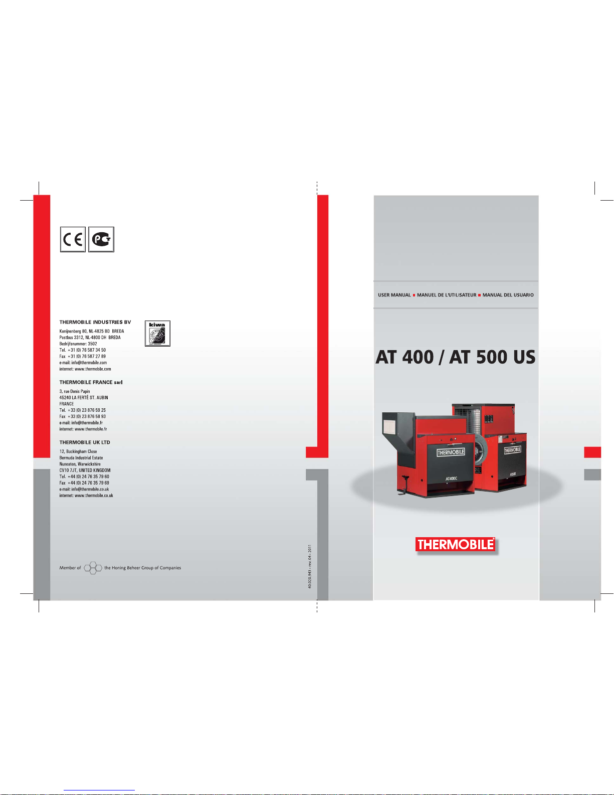
Identification of the product (fig. 1)
The identification plate is attached to the side
of the heater. The identification plate contains
the following data:
A Year of manufacture
B Serial number
C Production code
D Voltage data
E Air displacement
F Capacity max (kW)
G Capacity max (MJ/h)
H Type of machine
Service and technical support
Please contact your dealer or the
manufacturer for information about the
heater. Make sure you have the following
data at hand: type and serial number of the
stationary used oil fired heater.
Warranty and liability
For warranty and liability, see general
warranty regulations.
Environment
Note
The heater is made of various metals
and synthetic materials. The heater
also contains electronic parts, which
must be treated as electronic waste.
Please contact your dealer for further
information.
1 SAFETY INSTRUCTIONS
1.1 Pictograms in this manual
Caution
Indicates risk of damage to the
appliance.
Warning
Indicates a dangerous situation, that
can lead to death or serious injuries.
Warning
Always switch off power when
performing maintenance or repairs on
the hot air heater!
Hot
Some surfaces may be hot! Wait until
these parts have sufficiently cooled
down before performing
maintenance.
Suggestions and tips to simplify the
carrying out of the specified tasks or
actions.
1.2 Pictograms on the stationary used
oil fired heater (fig. 2)
A Warning for quantity of oil to be used
Instruction not to put the burner dish on a
cold surface
B Overheating thermostat
C Instruction for re-ignition.
D Positions of the burner: low and high.
AT 400 - 500-US series 40.020.943 - rev. 04 - 2011 5
English
1.3 Use this product for its intended
use
The stationary used oil fired hot air heater
has been designed for heating of workshops
at mechanization companies, heating and
frost protection of halls, transit sheds and
warehouses and heating of garage
workshops.
Caution
If the heater will be installed indoors,
make sure that there is proper
ventilation in the room. Make sure the
flue gas can only flow to an outside
source separate from the room.
1.4 General instructions
Warning
• Make sure that the heater is
properly installed, adjusted and
maintained.
• For all service and adjustments
contact qualified, competent and
authorized persons.
• Do not make any modifications to
the heater without the prior
written consent of the
manufacturer.
• Make sure to always follow the
local standards and guidelines as
well as the local requirements,
concerning environmental
quality, fuel, fire and electrical
safety.
• Read this manual carefully
before using the heater.
• Keep this document with the
heater.
• Follow the described procedures.
• Never lean against the heater.
Warning
• Do not create a fire hazard by
storing or using highly
inflammable materials near the
heater. Keep these materials at
adequate distance from the
heater:
- top and sides 6 inch (150
mm)
- front 35 inch (890 mm)
- back and flue 18 inch (460
mm)
• Make sure there is enough air for
proper combustion.
• Make sure that the convector
heater has cooled down
sufficiently and that the plug has
been removed from the socket
before carrying out any repair or
maintenance work.
1.5 Additional safety
Warning
• Connect the heater only to a
120 V / 60 Hz power supply.
• Replace fuses only with identical
spares.
• The heater must be grounded.
6 40.020.943 - rev. 04 - 2011 AT 400 - 500-US series

English
Warning
• Use only the following types of
fuel:
• Automatic transmission oil
• Crankcase oil
•Diesel oil
• Hydraulic oil
• Domestic fuel oil
• Do not add the following
materials to the used oil:
• Anti-freeze
• Carburettor cleaner
• Paint thinner
• Parts washer solvents
• Gasoline
• Transformer oil
• Oil additives
• Any other inappropriate or
hazardous material
• Do not fill the tank while the
heater operates.
2 INTRODUCTION
2.1 Purpose
These stationary used oil fired heaters are
direct fired heaters with thermal protection,
heat exchanger, combustion air fan, flue
stack connection with T-piece and draught
regulator and hot air fan.
The A T 500 is equipped with a connection for
a room thermostat
The hot air heaters have been tested at sea
level at a temperature of 68 °F.
2.2 Working principle
The stationary used oil fired heater is
equipped with three electric motors.
The first electric motor drives a fuel pump,
which extracts fuel from the fuel tank.
The second electric motor drives the
combustion air ventilator, which blows the
combustion air into the combustion chamber.
The third electic motor drives the hot air fan,
which draws the surrounding air around the
combustion chamber and heat exchanger.
The hot air is blown into the space to be
heated.
Diesel oil is poured manually on a burner
dish, which is ignited with a burning paper
pellet. As soon as the burner dish is at the
right temperature, the pump thermostat
activates the fuel pump; the control light
flashes on. The fuel pump pumps the used oil
onto the burner dish. The used oil evaporates
due to the temperature of the burner dish.
The gas vapour burns. A thermostat switches
on the hot air fan motor to blow hot air into
the space to be heated.
The pump thermostat switches off the fuel
pump when a failure causes the heater to
overheat.
The fuel pump is switched off when the
heater is switched off.
The hot air ventilator runs until the
combustion air thermostat switches off the
ventilator: this allows the heater to cool down.
The maximum thermostat switches off the
heater when the temperature gets too high.
The fuel supply has an overflow that ensures
that the used oil flows back into the fuel tank
when the fuel pipe is blocked.
The overflow protection switches off the fuel
pump when the burner dish overflows.
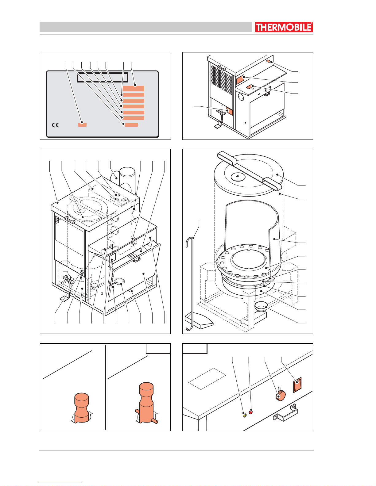
2.3 Main components of the stationary
used oil fired heater (fig. 3)
ACover
B Combustion chamber
C Heat exchanger
D Maximum thermostat
E Thermostats
F T-piece with draught regulator
G Hot air fan
H Combustion air ventilator
I Fill filter
J Control panel
K Fuel tank
LDrain cock
M Fuel filter
N Fuel pump
O Identification plate
P Return line
QDrawer
R Fuel pipe
S Fuel supply pipe
AT 400 - 500-US series 40.020.943 - rev. 04 - 2011 7

English
2.4 Main components of the burner
(fig. 4)
A Cover combustion chamber
B Combustion chamber
C Flame trap
D Burner ring
ESeal cord
F Burner dish
G Vaporiser
H Bottom combustion chamber
I Overflow protection
JShovel
2.5 Control panel (fig. 6)
A Indicator light, yellow
B Indicator light, red
C Bolt fuel tank
D Rocker switch:
- 0: The pump is switched off
- 1: The pump is in operation
- 2: High pump speed (only for AT 500)
2.6 Thermostat
The heater has the following thermostats:
• Pump thermostat
When the burner dish is sufficiently preheated, the fuel pump starts up.
• Hot air thermostat:
The thermostat starts the hot air fan
when the heater reaches a certain
temperature.
• Maximum thermostat
The thermostat stops the fuel pump when
the hot air temperature gets too high.
2.7 Accessories
•Flue with rain cap
3 PREPARATIONS
3.1 Removing the packaging
1. Remove packaging from the hot air
heater
2. Remove packaging from the loose parts
in the combustion chamber.
3.2 Installation
1. Ensure that the heater is positioned
horizontally.
2. Correctly attach the parts of the
combustion chamber, see fig. 4.
3. Attach the various handles to the cover
and the drawer, see fig. 3.
4. Push the tank bolt up, see fig. 5 (D).
5. Pull the fuel tank forward.
6. Fill the fuel tank through the tank filter
with used oil, until the level of used oil is
1 inch below the top of the tank.
Caution
Only the following oil types may be
used in the stationary used oil fired
heaters:
• Automatic transmission oil
•Diesel oil
• Hydraulic oil
• Oil for household use
Note
• Install the equipment in the US
according to the following
publications of the National Fire
Protection Association:
• NFPA #30: Flammable and
Combustible
• Liquids Code
• NFPA #31: Oil Burning
Equipment
• NFPA #88A: Parking
Structures
• NFPA #88B: Repair Garages
• NFPA #211: Chimneys,
Fireplaces and Vents
• Local codes may require that the
heater is mounted at a minimum
of 8 feet (2.4 m) off the ground.
This is especially the case when
there are possible combustible or
flamable fumes in the room.
Refer to NFPA #88B.
• Install the equipment in Canada
according to the following
standard: CSA B139, installation
Code for Oil Burning Equipment.
8 40.020.943 - rev. 04 - 2011 AT 400 - 500-US series

English
Place the heater on a location with
respect to the following:
• Possibility of unobstructed, even
heat distribution.
• Safe and easy access for
servicing.
• Unobstructed passage for shop
vehicles and equipment.
• Proper clearances for
combustibles. Refer to the safety
section.
• Adequate combustion air per
local codes. The room must be
ventilated to provide sufficient
combustion-air. The maximum air
consumption is 12 USG/h (46 m
h)
• Proper installation of the stack.
• The structure in which the heater
is located requires the following
minimum dimensions:
• height from the point of
location of the heater: 15 feet
(4.5 m).
• length and width: 20 feet
(6 m).
• floor area: 400 square feet
2
(36 m
)
• Possibility to place the heater on
a combustible flooring.
• If the heater is installed at an
elevation, a permanent platform,
including stairs and railings, must
be provided to facilitate regular
maintenance.
7. Close the fuel tank: Ensure that it is
locked.
8. Ensure that the hot air can flow out freely.
9. Ensure that inflammable materials are at
a sufficient distance from the heater, see
1.4.
10. Ensure there is sufficient ventilation: the
maximum air consumption is 2650 ft
3
/
hour.
11. Check the floor surface: this needs to be
at least 645 ft
2
.
12. Install the flue (18 ft and a rain cap).
13. Make sure the rocker switch is positioned
at 0.
14. Check the supply voltage: see
identification plate.
15. Place the plug in the socket.
3.3 Preparing for start-up
1. Switch the rocker switch to "0".
2. Only for the AT 400:
Switch control (A) of the fuel pump to
"low", see (fig. 5).
3. Drain possible water of condensation
from the fuel tank, see fig. 3 (L).
4. Open the drawer: Push pedal (A) down
and keep it down, lift safety (B) up, turn
3
/
control (C) left or right and let go of the
pedal, see fig. 7. Pull drawer (D) forward.
5. Check whether the burner dish and the
floor of the combustion chamber are
clean and cold.
6. Clean the burner dish and the floor of the
combustion chamber if necessary.
7. Pour 0.3 litre of diesel oil onto the burner
dish, see fig. 4 (F).
Warning
Never pour diesel oil onto a hot
burner dish.
The burner dish must be cool!
8. Form a paper pellet and light it.
9. Drop the burning pellet on the burner
dish.
10. Close the drawer.
1 1. Check through the upper cover that there
is no flame around the seal cord and
between the bottom and the combustion
chamber, see fig. 4.
AT 400 - 500-US series 40.020.943 - rev. 04 - 2011 9
English
3.4 Starting up
Warning
• Never pour diesel oil onto a hot
burner dish. The burner dish
must be cool and clean!
• Do not start the heater if the fan
still runs. The heater is cooling
down.
• Do not start the heater if excess
oil has accumulated in or near
the heater.
Caution
Do not switch on the convector
heater if there is no fuel, or if the
connected fuel tank is empty.
Caution
Only the following oil types may be
used in the stationary used oil fired
heaters:
• Automatic transmission oil
• Crankcase oil
• Diesel oil
• Hydraulic oil
• Domestic fuel oil
1. Switch the rocker switch to "2", see fig. 6
(D).
When the burner dish has reached the
right temperature, the fuel pump starts
running and the control light is on.
2. During the first 20 - 30 minutes the fuel
pump should have a low capacity.
For AT 400:
Position the rocker switch to "low", see
fig. 5 (A).
For AT 500:
The yellow control light is on, see fig. 6
(A).
3. Set the pump regulator to high capacity if
maximum capacity is desired.
For AT 400:
Switch the rocker switch to "high", see
fig. 5 (B).
For AT 500:
Switch the rocker switch to "2", see fig. 6
(D).The red control light is on, see
fig.6(B).
4USE
4.1 During operation
Caution
• Do not operate the heater in hot
weather to burn oil.
• Do not burn used oils other than
generated on the premiss of the
owner, unless written
authorization is obtained from the
regulatory authority.
Hot
Do not touch the flue stack or blower
outlet! The flue stack and blower
outlet get hot during operation!
4.2 Switching off
Switch off heating:
1. Switch the rocker switch to "0".
The fuel pump stops running.
The control light turns off.
Caution
After switching off the heater it will
run for several minutes, until the fuel
on the burner dish is used up. In the
meantime the hot air fan and the
distributor fan keep running. These
fans cool the heater until it has
sufficiently cooled down (after 10 to
30 minutes).
Both fans will stop around the same
time.
10 40.020.943 - rev. 04 - 2011 AT 400 - 500-US series
5 MAINTENANCE
English
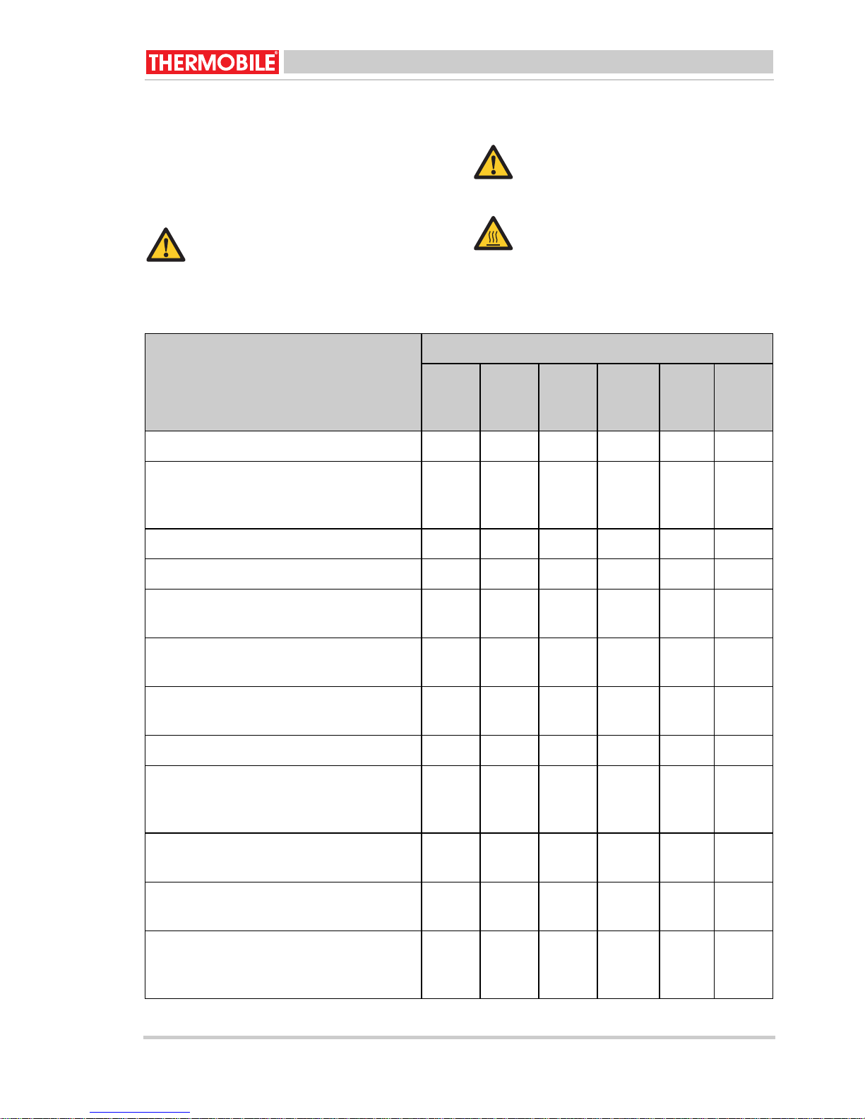
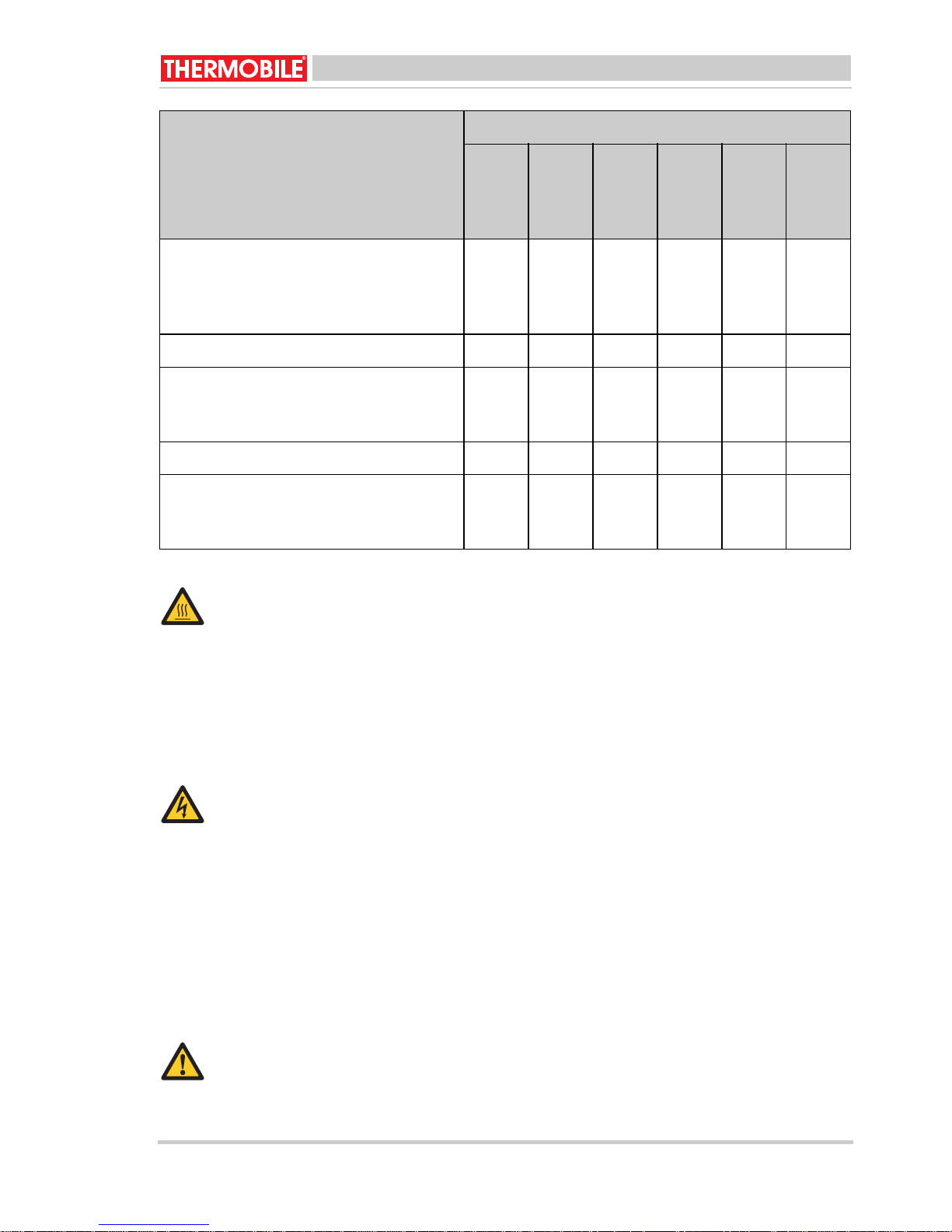
5.1 Maintenance table
Use the table in this booklet to record
performed maintenance after each winter
season.
Warning
For all service and adjustments
contact qualified, competent and
authorized persons.
Description Period
Every
12
hours
Clean the burner dish. X
Drain (water of) condensation from the
fuel tank, when the waste oil contains
water.
Clean the combustion chamber. X
Warning
Always clean the combustion
chamber before starting the heater.
Hot
Do not touch the flue and air outlet!
Wait until the flue and the air outlet
have cooled down sufficiently before
carrying out any maintenance.
/i
Week-lyMonth-lyEvery
six
months
X
Annually
Every
two
years
Clean the burner ring. X
Clean the combustion chamber and the
X
vaporiser with a steel brush.
Clean the combustion chamber and the
X
vaporiser with a steel brush.
Clean the overflow pipe in the floor of
X
the combustion chamber. See fig. 4(I).
Check the oil pipes for leakage. X
Clean the fuel tank, the supply filter and
the fuel filter.
The fuel tank can easily be removed.
Check the combustion air fan and clean
if necessary.
Check the hot air fan and clean if necessary.
Clean the flue stack valve in the T-piece,
Dealer
see fig. 8 (A).
The recommended draught is 2 mmwk.
X
X
X
AT 400 - 500-US series 40.020.943 - rev. 04 - 2011 11
English
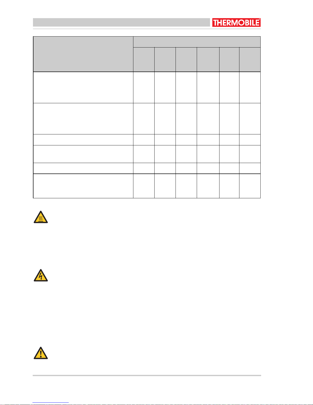
Description Period
Every
12
hours
Check the seal between the bottom and
Week-lyMonth-lyEvery
six
months
X
the vaporiser for leakage.
Adjust the pressure on the seal cord, or
replace the seal.
Replace the seal cord in the bottom.
X
Check the seal ring for leakage.
Adjust the pressure on the seal cord in
case of a leakage.
Clean the heat exchanger. X
Clean the flue stack T-piece, see "clean-
ing the flue stack valve".
Check the heater's wiring. X
Clean the heat exchanger.
Take the heat exchanger apart for a
good cleaning.
Annually
X
X
Every
two
years
Hot
Do not touch the flue stack or
combustion chamber!
Do not perform maintenance until the
flue and combustion chamber have
cooled down.
5.2 General
Warning
Switch off the power supply before
carrying out any repairs!
When the heater is stored long-term:
1. Switch off the heater.
2. Disconnect the power plug.
3. Clean the heater.
4. Use an oily cloth to clean the combustion
chamber, to protect the combustion
chamber against corrosion.
Warning
Do not operate the heater in hot
weather to burn oil.
5.3 Cleaning the combustion
chamber(fig. 4)
1. Open the cover of the heater, see fig. 4
(A).
2. Remove the burner ring (D) with the hook
of the shovel (J).
3. Clean the burner ring with a steel brush.
4. Remove the burner dish (F) with the hook
of the shovel.
5. Clean the burner dish with a scraper.
12 40.020.943 - rev. 04 - 2011 AT 400 - 500-US series
English
6. Clean the inner side of the combustion
chamber (B) and the vaporiser (G) with
the front of the shovel.
Note
• Used oils can contain heavy
metallic compounds and foreign
materials. These materials stay
as a residu when burned.
Therefore it is necessary to take
care when using, cleaning and
maintaining the heater.
• Wear protective gear when
cleaning the inside of the heater:
• Respirator for fine particles
• Rubber gloves
• Safety goggles
• Protective clothing
• Ensure that the holes in the
combustion chamber wall remain
open for combustion air supply.
7. Remove any soot pieces from the floor of
the combustion chamber.
8. Clean the inside of the pipe in the
vaporiser with a small brush (diameter 4
mm).
9. Clean the fuel supply line (N) with a
brush (inner diameter 0.33 in), see fig. 3.
10. Install all parts in reversed order.
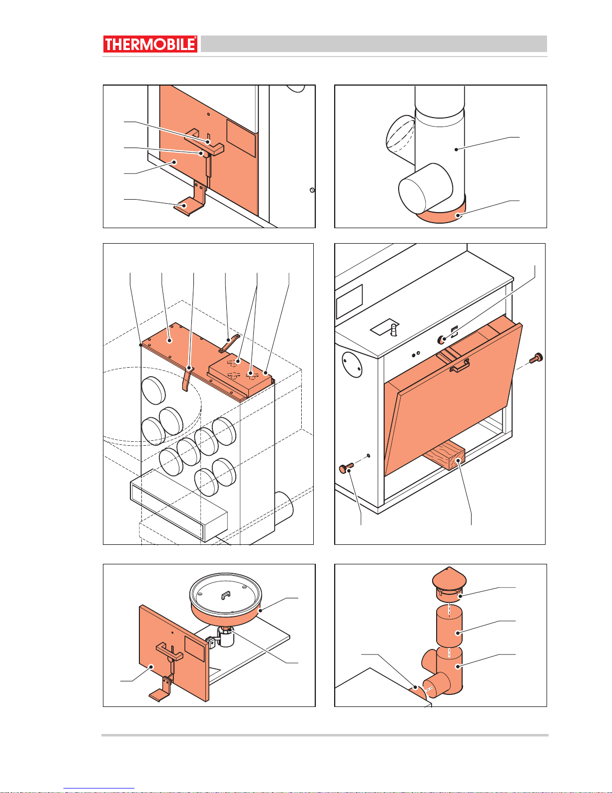
5.4 Cleaning the heat exchanger (fig.
9)
1. Disconnect the power connection from
the heater.
2. Open the cover, see fig. 3 (A).
3. Unscrew the thermostat clamp (A).
4. Take the wiring off both thermostats (B).
5. Remove safety strip (C).
6. Remove safety strip (D).
7. Remove cover (E) from the heat
exchanger.
8. Clean the inner side of the heat
exchanger with a brush and vacuum
cleaner.
9. Re-install the cover of the heat
exchanger.
Always attach a new gasket (F)
between the cover and the heat
exchanger.
Install all parts in reversed order.
Apply the wiring of the thermostats
according to the electrical circuit
diagram. The thermostats are equal.
5.5 Taking t he heat exchanger apart
(fig. 9)
1. Disconnect the power connection from
the heater.
2. Remove the T-piece (A) from the flue,
see fig. 3 (F).
3. Remove the grate, see fig. 3 (A).
4. Unscrew the thermostat clamp (A).
5. Take the wiring off both thermostats (B).
6. Remove safety strip (C).
7. Remove safety strip (D).
8. Remove the fuel supply pipe, see fig. 3
(S).
9. Unscrew the overflow cup support and
put the overflow protection on the floor of
the heater.
10. Remove the combustion air fan (H) with
motor support, see fig. 3.
11. Unscrew the back panel from the heater
and turn it 180° to the fuel tank.
Temporarily support the back panel in
this position.
12. Remove the casing of the combustion air
fan.
Warning
Do not change the position of the
valve in the casing.
13. Unscrew the frame of the combustion
chamber from the groundplate of the
heater.
AT 400 - 500-US series 40.020.943 - rev. 04 - 2011 13

English
14. Lift the combustion chamber with heat
exchanger from the heater.
Do this with another person.
15. Unscrew the connection of the
combustion chamber and the heat
exchanger.
16. Remove the strip between the
combustion chamber and the heat
exchanger.
17. Pull the heat exchanger from the
combustion chamber.
18. Remove upper and lower cover of the
heat exchanger.
19. Clean the heat exchanger internally with
a brush and remove dirt with a vacuum
cleaner.
20. Re-install the upper and lower cover of
the heat exchanger.
Always apply new gaskets between
the upper and lower cover and the
heat exchanger.
Re-install the heater in reversed order.
Apply the wiring of the thermostats
according to the electrical circuit
diagram. The thermostats are equal.
Reposition the bottom cover.
5.7 Removing the fuel tank (fig. 10)
1. Drain the fuel tank through the drain
cock, see fig. 3 (L).
2. Push the tank bolt up, see fig. 10 (C).
3. Support the fuel tank with a woo den reel
(A).
4. Remove the black knurled bolt (B) on the
left and right side of the fuel tank.
5. Remove the fuel tank using both hands
by grasping the bottom of the tank.
6. Remove the wooden reel.
7. Gently lower the fuel tank and take the
fuel tank from the heater.
Remove the fuel tank with care: the
fuel system is installed in the fuel
tank.
Install the fuel tank in reversed order.
5.8 Adjusting the pressure of the seal
cord (fig. 11)
1. Open the control panel (A), see 3.3.
2. Unscrew nut (B).
3. Turn the bottom (C) of the vaporiser
slightly up or down (depending on the
situation).
4. Unscrew nut (B).
5. Push the control panel in the heater.
5.6 Cleaning the flue (fig. 8)
1. Remove the bottom cover (B) of the T-
Check whether the seal cord seals
properly when the heater is running.
piece (A).
2. Clean the flue from top to bottom with a
flue brush.
3. Check the connections for leakage.
4. Check the flue parts for rust.
Caution
Rust formation indicates that chlorine
6 FAULTS
Warning
For all service and adjustments
contact qualified, competent and
authorized persons.
containing materials have been
burnt.
Chlorine containing materials
seriously damage the heater. This
may void your warranty.
Contact your dealer for instructions
on how to test waste oil for chlorine.
Warning
Switch off the power supply before
carrying out any repairs!
Ensure that the power is switched on,
and the fuel tank is full, before you
start troubleshooting.
14 40.020.943 - rev. 04 - 2011 AT 400 - 500-US series
English
6.1 Troubleshooting table
/i
Fault Cause Solution Action
The flame is extinguished immediately
after ignition; the
control light is off.
1 The heater has no volt-
age.
2 The fuel pump is not
switched on.
3 The motor and pump
are not functioning.
Check the electric connec-
User
tion.
Position the switch to "1", see
User
fig. 5 (A).
Dilute the waste oil with die-
User
sel oil when the waste oil is
too viscous.
Check the pump thermostat
Dealer
and replace if necessary.
Check the overflow protec-
User
tion switch by moving the
overflow basin a few times
from left to right.
Check whether the pump
User
axis can be turned manually.
Clean the pump if this is not
possible.
Check the pump motor. Dealer
The flame is extinguished immediately
after ignition; the
control light is on.
4 The pump thermostat
has not reached the
right temperature yet.
5 The maximum thermo-
stat is defective.
6 The overflow protection
is full of waste oil.
7 There is water or sedi-
ment in the fuel tank.
8 The fuel supply pipe is
blocked: The fuel flows
back into the fuel tank
through the return pipe.
Let the heater cool down.
User
Restart the heater.
Replace the pump thermo-
Dealer
stat.
Reset the thermostat. User
Replace the thermostat. User
Clean the overflow basin,
User
burner dish and the bottom of
the vaporiser.
Clean the fuel tank and the
User
fuel filter, see fig. 3.
Clean the fuel supply pipe or
User
replace if necessary.
AT 400 - 500-US series 40.020.943 - rev. 04 - 2011 15
English
Fault Cause Solution Action
The flame is extinguished immediately
after ignition; the
control light is on.
The air combustion
fan keeps running,
while the hot air fan
has stopped and the
heater has cooled
down.
There is soot formation in the combustion chamber and in
the flue.
There is soot formation in the combustion chamber and in
the flue.
9 There is no proper flue
draught.
10 The combustion thermo-
stat is defective.
11 The combustion air fan
is not functioning.
12 There is insufficient sup-
ply of combustion air
Check whether the flue is fit-
User
ted according to the description, see "flue".
Check the flue for leakage. User
Clean the flue if necessary. User
See faults: 3 and 4.
Replace the combustion
User
thermostat.
Check the motor and replace
Dealer
if necessary.
Clean the holes in the vapor-
User
iser.
Check the functioning of the
User
combustion air fan.
There is leakage
between the bottom
of the control panel
and the vaporiser.
The flame goes out
directly after ignition.
13 The flue draught is too
high or irregular.
14 There is leakage
between the bottom of
the control panel and
the vaporiser.
15 The flue draught is too
low.
Position a flue stack valve,
Dealer
see "flue".
Adjust the flue to the right
pressure, see § 5.3.
See faults: 9, 12, and 13.
Adjust the pressure on the
User
seal cord.
Replace the seal cord. User
Check all connections in the
User
flue.
Check whether the draught
User
regulator is off.
Check the flue for blockage. User
Reduce the number of
User
bends.
Heighten the flue. User
16 40.020.943 - rev. 04 - 2011 AT 400 - 500-US series
English
Fault Cause Solution Action
The flame goes out
directly after ignition.
The heater makes a
humming sound.
The flue draught is too
low.
16 There is too much diesel
oil at start up.
There is unburnt fuel
on the burner dish.
Record the maintenance details in table A in
the appendix of this manual.
7 SPARE PARTS
Before use we advise you to have spare parts
in store, see table B in the appendix of this
manual.
Isolate the flue outside the
User
building.
Check the flue, see "flue". User
Reduce the amount of diesel
User
oil.
Low temperatures for single
User
walled flue, for instance in
case of frost.
The sound will stop when the
temperature rises.
See faults: 2, 11, 12, 13 and
14.
8 TECHNICAL INFORMATION
• See for technical specifications table C in
the appendix of this manual.
9 INSTALLING ACCESSORIES
9.1 Flue (fig. 12)
The heater has a flue stack connection.
1. Push a T-piece (A) directly over the
connection (B).
2. Push the flue pipe (C) on the T-piece.
3. Use three screws to screw the flue pipe
to the T-piece.
AT 400 - 500-US series 40.020.943 - rev. 04 - 2011 17
Caution
The flue must meet the following
requirements.
• The flue must be pointed upwards.
• The flue (or any part of it) may not be
positioned horizontally. A 45° angle is
acceptable.
• It is not allowed to lenghten the flue
connection horizontally.
• When a pipe is used under 45°, pipe
pieces of at least 3.2 ft must be fitted in
front of and at the back of the slanting
pipe.
English
• The flue must stick out at least 1.6 ft
above the apex of the building.
• Keep the vertical part at the back of the
heater as long as possible before leading
it outside through the wall.
4. Fit the following pipe pieces.
5. Place a cap (D) at the end of the flue.
9.2 Diameter flue
/i
AT 400 AT 500
6 inch 8 inch
10 STANDARDS AND GUIDELINES
For the standards and guidelines, go to
www.thermobile.nl.
18 40.020.943 - rev. 04 - 2011 AT 400 - 500-US series

Français
Français
Table des matières
Consignes de sécurité .............................. 19
Introduction............................................... 21
Préparations.............................................. 22
Emploi....................................................... 25
Entretien.................................................... 25
Erreurs...................................................... 30
Pièces détachées...................................... 34
Caractéristiques techniques...................... 34
Installation accessoires............................. 34
Normes et directives................................. 34
Avant-propos
Ce manuel contient les instructions
d'utilisation des générateurs alimentés à
l'huile à utilisation fixe présentés en
couverture. Pour une utilisation correcte et
sans risque du générateur, veuillez lire
attentivement les informations de ce manuel.
Identification du produit (fig. 1)
La plaque signalétique est fixée sur le côté
du générateur. Elle indique les données
suivantes :
A Année de fabrication
B Numéro de série
C Code de production
D Données de tension
E Déplacement d'air
F Capacité max (kW)
G Capacité max (MJ/h)
H Type de machine
Environnement
Remarque
Le générateur se compose de
plusieurs métaux et matériaux
synthétiques. Le générateur contient
également des pièces électroniques
qui doivent être traitées comme des
déchets électroniques. Veuillez
contacter votre revendeur pour en
savoir plus.
1 CONSIGNES DE SÉCURITÉ
1.1 Pictogrammes de ce manuel
Précaution
Indique le risque de dommages à la
machine.
Avertissement
Indique une situation dangereuse,
qui peut provoquer la mort ou des
blessures graves.
Avertissement
Toujours couper l'alimentation avant
tout entretien ou réparation sur le
générateur!
Chaud
Certaines surfaces peuvent être
chaudes ! Faire refroidir
suffisamment ces pièces avant tout
action d'entretien.
Maintenance et support technique
Pour obtenir des informations sur le
générateur, veuillez contacter le revendeur
ou le fabricant. Assurez-vous de disposer
des informations suivantes : type et numéro
de série du générateur alimenté à l'huile à
utilisation fixe.
Garantie et responsabilité
Pour des conditions de garantie, voir les
conditions générales de garantie.
AT 400 - 500-US series 40.020.943 - rev. 04 - 2011 19
Suggestions et conseils pour
effectuer plus aisément les tâches ou
activités en question.
1.2 Pictogrammes sur le générateur à
l'huile à utilisation fixe (fig. 2)
A Avertissement de quantité d'huile à
utiliser
Instruction pour ne pas placer le plateau
brûleur sur une surface froide
B Thermostat de surchauffe
C Instructions de rallumage.
D Positions du brûleur : bas et haut.

Français
1.3 Utilisez ce produit pour son usage
prévu
Le générateur d'air chaud alimenté à l'huile
pour utilisation fixe a été conçu pour le
chauffage des ateliers des sociétés
d'usinage, le chauffage et la protection contre
le gel des halls, zones de transit et entrepôts
et le chauffage des ateliers automobiles.
Précaution
Si le générateur est installé à
l'intérieur, assurez-vous que la pièce
est correctement ventilée. Assurezvous que les gaz de refoulement
peuvent uniquement passer dans une
source externe à la pièce.
1.4 Consignes générales
Avertissement
• Assurez-vous de l'installation, du
réglage et de l'entretien corrects
du générateur.
• Pour tout entretien ou réglage,
contactez des personnes
qualifiées, compétentes et
agréées.
• N'apportez aucune modification
au générateur sans l'accord écrit
préalable du fabricant.
• Assurez-vous de toujours
respecter les normes et
directives locales ainsi que les
obligations locales relatives à
l'environnement, la qualité, les
carburants, les incendies et la
sécurité électrique.
• Lisez attentivement ce manuel
avant d'utiliser le générateur.
• Conservez ce document près du
générateur pour toute utilisation
ultérieure.
• Suivez les procédures décrites.
• Ne vous appuyez jamais contre
le générateur.
Avertissement
• Ne créez aucun risque d'incendie
en stockant ou en utilisant des
matériaux hautement
inflammables à proximité du
générateur. Conservez ces
matériaux à une distance
adéquate du générateur :
- haut et côtés 6 pouce (150
mm)
- avant 35 pouce (890 mm)
- arrière et tuyau de cheminée
8 pouce (460 mm)
• Veillez à ce qu’il y ait assez d’air
frais pour que la combustion soit
satisfaisante.
• Assurez-vous que le générateur
a refroidi suffisamment et que le
bouchon a été retiré de la douille
avant tout entretien ou
réparation.
1.5 Sécurité additionnelle
Avertissement
• Connectez le générateur
uniquement à une alimentation
120 V / 60 Hz.
• Remplacez les fusibles
uniquement à l'identique.
• Le générateur doit être mis à la
terre.
20 40.020.943 - rev. 04 - 2011 AT 400 - 500-US series

Français
Avertissement
• Utilisez uniquement les types de
combustibles suivants :
• Huile transmission
automatique
• Huile de carter
•Diesel
• Huile hydraulique
• Fioul domestique
• N'ajoutez pas les matières
suivantes à l'huile utilisée :
• Antigel
• Nettoyant de carburateur
• Diluant pour peinture
• Solvants de nettoyage de
pièces
• Essence
• Huile de transformation
• Additifs d'huile
• Toute autre matière
dangereuse ou inappropriée
• Ne remplissez p as le rés ervoi r si
le générateur marche.
2 INTRODUCTION
2.1 But
Ces générateurs alimentés à l'huile à
utilisation fixe sont des générateurs à
alimentation directe avec protection
thermique, échangeur de chaleur, ventilateur
d'air de combustion, connexion de tuyau de
cheminée avec raccord en T et régulateur de
tirage et ventilateur d'air chaud.
L'AT 500 est équipé d'une connexion pour
thermostat d'ambiance
Les générateurs d'air chaud ont été testés au
niveau de la mer et à une température de
68 °F.
Le second moteur électrique entraîne le
ventilateur d'air de combustion qui souffle l'air
de combustion dans la chambre de
combustion.
Le troisième moteur électrique entraîne le
ventilateur d'air chaud qui tire l'air de la partie
autour de la chambre de combustion et de
l'échangeur de chaleur. L'air chaud est
soufflé dans l'espace à chauffer.
Le diesel est versé manuellement dans un
plateau brûleur qui est allumé par une
boulette de papier brûlante. Dès que le
plateau brûleur est à la bonne température,
le thermostat de la pompe active la pompe à
combustible. Le témoin de contrôle s'allume.
La pompe de carburant pompe l'huile utilisée
dans le plateau brûleur. L'huile utilisée
s'évapore en raison de la température du
plateau brûleur. Les vapeurs gazeuses
brûlent. Un thermostat enclenche le moteur
du ventilateur d'air chaud pour souffler l'air
chaud dans l'espace à chauffer.
Le thermostat de la pompe coupe la pompe à
combustible en cas de panne provoquant
une surchauffe du générateur.
La pompe à combustible est coupée lorsque
le générateur est coupé.
Le ventilateur d'air chaud fonctionne jusqu'à
ce que le thermostat d'air de combustion
l'arrête : le générateur peut ainsi refroidir.
Le thermostat maximum coupe le générateur
lorsque la température est trop élevée.
L'alimentation en combustible présente un
trop plein qui garantit que l'huile utilisée
retourne dans le réservoir de combustible
lorsque le tuyau de combustible est bouché.
La protection de trop plein coupe la pompe à
combustible lorsque le plateau brûleur
déborde.
2.2 Principe de fonctionnement
Les générateurs alimentés à l'huile à
utilisation fixe sont équipés de trois moteurs
électriques.
Le premier moteur électrique entraîne une
pompe à combustible qui extrait le
combustible du réservoir de combustible.
AT 400 - 500-US series 40.020.943 - rev. 04 - 2011 21

Français
2.3 Principaux composants des
générateurs alimentés à l'huile à
utilisation fixe (fig. 3)
A Cache
B Chambre de combustion
C Échangeur de chaleur
D Thermo stat maximum
E Thermostats
F Raccord en T avec régulateur de tirage
G Ventilateur d'air chaud
H Ventilateur d'air de combustion
I Filtre de remplissage
J Panneau de commande
K Réservoir de combustible
L R obinet de purge
M Filtre à combustible
N Pompe à combustible
O Plaque signalétique
P Conduite de retour
QTiroir
R Tuyau de combustible
S Tuyau d'alimentation en combustible
2.4 Principaux composants du brûleur
(fig. 4)
A Cache chambre de combustion
B Chambre de combustion
C Pare-flamme
D Bague de brûleur
E Bourrelet de joint
F Plateau brûleur
G Vaporisateur
H Fond de chambre de combustion
I Protection de trop plein
J Pelle
2.5 Panneau de commande (fig. 6)
A Témoin jaune
B Témoin rouge
C Bou lon réservoir de combustible
D Interrupteur à bascule :
- 0: La pompe est arrêtée
- 1: La pompe fonctionne
- 2: Vitesse pompe élevée
(uniquement pour AT 500)
2.6 Thermostat
Le générateur comporte les thermostats
suivants :
• Thermostat de pompe
Lorsque le plateau brûleur est
suffisamment préchauffé, la pompe à
combustible se met en marche.
• Thermostat d'air chaud :
Le thermostat lance le ventilateur d'air
chaud lorsque le générateur atteint une
certaine température.
•Thermostat maximum
Le thermostat coupe la pompe à
combustible lorsque la température de
l'air chaud est trop élevée.
2.7 Accessoires
• Tuyau de cheminée avec capuchon antipluie
3 PRÉPARATIONS
3.1 Retrait de l’emballage
1. Enlevez l’emballage du générateur d'air
chaud.
2. Retirez l'emballage des pièces libres de
la chambre de combustion.
3. Retirez l'emballage des pièces libres de
la chambre de combustion.
3.2 Installation
1. Vérifiez que le générateur est à
l'horizontale.
2. Fixez correctement les pièces de la
chambre de combustion, voir fig. 4.
3. Fixez les diverses poignées au cache et
au tiroir, voir fig. 3.
4. Poussez le boulon du réservoir vers le
haut, voir fig. 5 (D).
5. Tirez le réservoir de combustible vers le
haut.
22 40.020.943 - rev. 04 - 2011 AT 400 - 500-US series

Français
6. Remplissez le réservoir de combustible
avec l'huile utilisée pour que le niveau
soit 1 pouce sous le haut du réservoir.
Précaution
Seuls les types de combustibles
suivants peuvent être utilisés avec
les générateurs alimentés à l'huile à
utilisation fixe :
• Huile transmission automatique
•Diesel
• Huile hydraulique
• Huile à usage domestique
Remarque
• Installez l'équipement aux ÉtatsUnis selon les publications
suivantes de la National Fire
Protection Association :
• NFPA #30: Flammable and
Combustible Liquids Code
• NFPA #31: Oil Burning
Equipment
• NFPA #88A: Parking
Structures
• NFPA #88B: Repair Garages
• NFPA #211: Chimneys,
Fireplaces and Vents
• Les codes locaux peuvent exiger
le montage du générateur à un
minimum de 8 pied (2.4 m) m du
sol. C'est spécialement le cas si
la pièce peut contenir des
fumées combustibles ou
inflammables. Voir NFPA #88B.
• Installez l'équipement au Canada
selon les normes suivantes :
CAN B139, Code d'installation
pour équipement de combustion
d'huile.
Placez le générateur dans un endroit
respectant les conditions suivantes :
• Possibilité d'une distribution
uniforme et libre de la chaleur.
• Accès sécurisé et facile pour
l'entretien.
• Passage libre pour les véhicules
et équipement d'atelier.
• Distance adaptée des
combustibles. Voir la section
Sécurité.
• Air de combustion adéquat selon
les codes locaux. La pièce doit
être ventilée afin de fournir
suffisamment d'air de
combustion. La consommation
maximum d'air est de 12 USG/h
3
(46 m
/h.
• Installation correcte du tuyau.
• La structure dans laquelle le
générateur se trouve doit
présenter les dimensions
minimum suivantes :
• hauteur depuis le point
d'emplacement du
générateur : 15 pied (4.5 m).
• longueur et largeur : 20 pied
(6 m).
• surface au sol : 400 pied
carré (36 m
2
).
• Possibilité de placer le
générateur sur un sol
combustible.
• Si le générateur est installé en
hauteur, une plate-forme
permanente, incluant des
escaliers ou des rampes, doit
être prévue pour faciliter
l'entretien régulier.
AT 400 - 500-US series 40.020.943 - rev. 04 - 2011 23
7. Fermez le réservoir de combustible :
vérifiez qu'il est verrouillé.
8. Veillez également à ce que le flux d’air
réchauffé ne soit pas obstrué.
9. Assurez-vous que les matériaux
inflammable sont suffisamment éloignés
du générateur, voir 1.4.

Français
10. Assurez-vous que la ventilation soit
suffisante : la consommation maximum
d'air est de 2650 ft
3
/h.
11. Vérifiez la surface au sol : elle doit
mesurer au moins 645 ft
2
.
12. Installez le tuyau de cheminée (18 ft de
long et un capuchon anti-pluie)
13. Assurez-vous que l'interrupteur à bascule
est sur 0.
14. Vérifiez la tension d’alimentation : pour
cela, consulter la plaque signalétique.
15. Branchez la prise électrique.
3.3 Préparation à démarrage
1. Positionnez l'interrupteur à bascule sur
"0".
2. Uniquement pour l'AT 400 :
Positionnez l'interrupteur (A) de la pompe
à combustible sur "bas", voir (fig. 5).
3. Purgez le condensat potentiel du
réservoir de combustible, voir fig. 3 (L).
4. Ouvrez le tiroir : enfoncez la pédale (A)
sans la relâcher , soulevez la sécurité (B),
tournez la commande (C) à droite ou à
gauche et lâchez la pédale, voir fig. 7.
Tirez le tiroir (D) en avant.
5. Vérifiez si le plateau brûleur et le fond de
la chambre de combustion sont propres
et froids.
6. Nettoyez le plateau brûleur et le fond de
la chambre de combustion, si nécessaire.
7. Versez 0,3 litre de diesel sur le plateau
brûleur, voir fig. 4 (F).
Avertissement
Ne versez jamais le diesel sur un
plateau brûleur chaud.
Le plateau brûleur doit être froid !
8. Formez une boulette de papier et
allumez-la.
9. Jetez la boulette de p apier brûlante sur le
plateau brûleur.
10. Fermez le tiroir.
11. Vérifiez à travers le cache supérieur
qu'aucune flamme ne se trouve autour du
bourrelet de joint et entre le fond et la
chambre de combustion, voir fig. 4.
3.4 Démarrage
Avertissement
• Ne versez jamais le diesel sur un
plateau brûleur chaud. Le
plateau brûleur doit être froid et
propre !
• Ne démarrez pas le générateur
si le ventilateur tourne encore. Le
générateur refroidit.
• Ne démarrez pas le générateur
si l'huile s'est excessivement
accumulée dans le générateur
ou à proximité.
Précaution
Ne mettez pas le générateur en
marche en l'absence de combustible
ou si le réservoir de combustible
connecté est vide.
Précaution
Seuls les types de combustibles
suivants peuvent être utilisés avec
les générateurs alimentés à l'huile à
utilisation fixe :
• Huile transmission automatique
• Huile de carter
•Diesel
• Huile hydraulique
• Fioul domestique
1. Positionnez l'interrupteur à bascule sur
"2", voir fig. 6 (D).
Lorsque le plateau brûleur a atteint la
bonne température, la pompe à
combustible se met en marche et le
témoin de contrôle s'allume.
2. Pendant les 20 à 30 premières minutes,
la pompe à combustible devrait avoir une
faible capacité.
Pour AT 400 :
Positionnez l'interrupteur à bascule sur
"bas", voir fig. 5 (A).
Pour AT 500 :
24 40.020.943 - rev. 04 - 2011 AT 400 - 500-US series

Français
Le témoin jaune est allumé, voir fig. 6 (A).
3. Réglez le régulateur de pompe sur haute
capacité si la capacité maximum est
nécessaire.
Pour AT 400 :
Positionnez l'interrupteur à bascule sur
"haut", voir fig. 5 (B).
Pour AT 500 :
Positionnez l'interrupteur à bascule sur
"2", voir fig. 6 (D). Le témoin rouge est
allumé, voir fig. 6 (B).
4EMPLOI
4.1 Au cours du fonctionnement
Précaution
• N'utilisez pas le générateur par
temps chaud pour brûler de
l'huile.
• Ne brûlez aucune huile usée
exceptée celle générée sur le
site du propriétaire, sauf
autorisation écrite de l'autorité
régulatoire.
Chaud
Ne touchez pas au tuyau de
cheminée ni à la sortie d'air ! Le
tuyau de cheminée et la sortie d'air
deviennent chauds pendant le
fonctionnement!
4.2 Arrêt
Arrêt du chauffage:
1. Positionnez l'interrupteur à bascule sur
"0".
La pompe à combustible s'arrête.
Le témoin de contrôle s'éteint.
Précaution
Une fois le générateur arrêté, il
continue de tourner plusieurs
minutes pour consommer tout le
combustible du plateau brûleur.
Pendant ce temps, le ventilateur d'air
chaud et le ventilateur de diffusion
continuent de tourner. Ces
ventilateurs refroidissent le
générateur jusqu'à ce qu'il soit
suffisamment froid (après 10 à 30
minutes).
Les deux ventilateurs s'arrêtent à
peu près au même moment.
5ENTRETIEN
5.1 Tableau d’entretien
Utilisez le tableau dans ce manuel pour
enregistrer l'entretien effectué après chaque
saison d'hiver.
Avertissement
Pour tout entretien ou réglage,
contactez des personnes qualifiées,
compétentes et agréées.
AT 400 - 500-US series 40.020.943 - rev. 04 - 2011 25
Avertissement
Nettoyez toujours la chambre de
combustion avant de démarrer le
générateur.
Chaud
Ne touchez ni au tuyau de cheminée
ni à la sortie d’air !
Attendez que le tuyau de cheminée
et la sortie d'air aient suffisamment
refroidi avant d'effectuer tout
entretien.

Français
/i
Description Fréquence
Nettoyez le plateau brûleur. X
Purgez la condensation (l'eau) du réser-
voir de combustible si le déchet d'huile
contient de l'eau.
Nettoyez la chambre de combustion. X
Nettoyez la bague du brûleur. X
Nettoyez la chambre de combustion et
le vaporisateur avec une brosse à dents.
Nettoyez la chambre de combustion et
le vaporisateur avec une brosse à dents.
Nettoyez le tuyau de trop plein au fond
de la chambre de combustion. Voir fig. 4
(I).
Vérifiez si les tuyaux d'huile présentent
une fuite.
Toutes les
12
heures
X
X
Hebdomadaire
X
Mensuel
X
Tous
les six
mois
X
Annuel Tous
les
deux
ans
Nettoyez le réservoir de combustible, le
filtre d'alimentation et le filtre à combustible.
Le réservoir à combustible est facilement amovible.
Contrôlez le ventilateur d'air de combustion et nettoyez-le au besoin.
Contrôlez le ventilateur d'air chaud et
nettoyez-le au besoin.
Nettoyez la vanne de tuyau de cheminée dans la pièce en T, voir fig. 8 (A).
Le tirage recommandé est de 2 mmce.
Vérifiez les traces de fuite au niveau du
joint entre le fond et le vaporisateur.
Réglez la pression sur le bourrelet de
joint ou remplacez le joint.
X
X
X
Revendeur
X
26 40.020.943 - rev. 04 - 2011 AT 400 - 500-US series
Description Fréquence
Français
Toutes les
12
Hebdomadaire
Mensuel
Tous
les six
mois
heures
Remplacez le bourrelet de joint au fond.
X
Vérifiez si la bague de joint fuit.
Réglez la pression sur le bourrelet de
joint en cas de fuite.
Nettoyez l’échangeur de chaleur. X
Nettoyez la pièce en T du tuyau de che-
minée, voir "nettoyage de la vanne de
tuyau de cheminée".
Vérifiez le câblage du générateur. X
Nettoyez l’échangeur de chaleur.
Retirez l'échangeur de chaleur pour le
nettoyer correctement.
Chaud
Ne touchez pas au tuyau de
cheminée ni à la chambre de
combustion !
N'effectuez aucun entretien tant que
le tuyau de cheminée et la chambre
de combustion n'ont pas refroidi.
5.3 Nettoyage de la chambre de
combustion(fig. 4)
1. Ouvrez le cache du générateur, voir fig. 4
(A).
2. Retirez la bague du brûleur (D) avec le
crochet de la pelle (J).
3. Nettoyez la bague du brûleur avec une
brosse d'acier.
5.2 Général
Avertissement
Coupez l'alimentation électrique
avant toute réparation !
4. Retirez le plateau brûleur (F) avec le
crochet de la pelle.
5. Nettoyez le plateau brûleur avec un
grattoir.
Annuel Tous
les
deux
ans
X
X
Si le générateur est stocké pendant une
période prolongée :
1. Éteignez le générateur.
2. Débranchez la prise d'alimentation.
3. Nettoyez le générateur.
4. Utilisez un chiffon huileux pour nettoyer
la chambre de combustion afin de la
protéger de la corrosion.
Avertissement
N'utilisez pas le générateur par
temps chaud pour brûler de l'huile.
AT 400 - 500-US series 40.020.943 - rev. 04 - 2011 27

Français
6. Nettoyez l'intérieur de la chambre de
combustion (B) et du vaporisateur (G)
avec l'avant de la pelle.
Remarque
• Les huiles utilisées peuvent
contenir des composés
métalliques et des substances
étrangères. Ces matières restent
sous forme de résidus une fois
brûlées. Il est donc nécessaire de
faire attention en utilisant, en
nettoyant et en entretenant le
générateur.
• Portez un équipement de
protection pour nettoyer
l'intérieur du générateur :
• Respirateur pour particules
fines
• Gants en caoutchouc
• Lunettes de sécurité
• Vêtements de protection
• Assurez-vous que tous les
orifices de la chambre de
combustion restent ouverts pour
alimenter la combustion en air.
7. Retirez toute trace de suie du fond de la
chambre de combustion.
8. Nettoyez l'intérieur du tuyau du
vaporisateur avec une petite brosse
(diamètre 4 mm).
9. Nettoyez la conduite alimentation en
combustible (N) avec une brosse
(diamètre intérieur de 8,38 mm), voir fig.
3.
10. Installez les pièces en ordre inverse.
5.4 Nettoyage de l’échangeur de
chaleur (fig. 9)
1. Déconnectez l'alimentation électrique du
générateur.
2. Ouvrez le cache, voir fig. 3 (A).
3. Dévissez la fixation du thermostat (A).
4. Retirez le câblage des deux thermostats
(B).
5. Ôtez la barrette de sécurité (C).
6. Ôtez la barrette de sécurité (D).
7. Retirez le cache (E) de l'échangeur de
chaleur.
8. Nettoyez l'intérieur de l'échangeur de
chaleur avec une brosse et un aspirateur.
9. Installez à nouveau le cache de
l'échangeur de chaleur.
Prévoyez toujours un joint (F) neuf
entre le cache et l'échangeur de
chaleur.
Installez les pièces en ordre inverse.
Replacez le câblage des thermostats
selon le diagramme de circuit
électrique. Les thermostats sont
identiques.
5.5 Retrait de l'échangeur de chaleur
(fig. 9)
1. Déconnectez l'alimentation électrique du
générateur.
2. Retirez le raccord en T (A) du tuyau de
cheminée, voir fig. 3 (F).
3. Retirez la grille, voir fig. 3 (A).
4. Dévissez la fixation du thermostat (A).
5. Retirez le câblage des deux thermostats
(B).
6. Ôtez la barrette de sécurité (C).
7. Ôtez la barrette de sécurité (D).
8. Retirez le tuyau d'alimentation en
combustible, voir fig. 3 (S).
9. Dévissez le support de cuvette de trop
plein et placez la protection de trop plein
sur le fond du générateur.
10. Retirez le ventilateur d'air de combustion
(H) avec le support de moteur, voir fig. 3.
11. Dévissez le panneau arrière du
générateur et tournez-le à 180° vers le
réservoir de combustible.
Soutenez temporairement le panneau
arrière dans cette position.
12. Retirez le carter du ventilateur d'air de
combustion.
Avertissement
Ne modifiez pas la position de la
vanne dans le carter.
28 40.020.943 - rev. 04 - 2011 AT 400 - 500-US series

Français
13. Dévissez le cadre de la chambre de
combustion de la plaque de fond du
générateur.
14. Levez la chambre de combustion avec
l'échangeur de chaleur hors du
générateur.
Demandez de l'aide à une autre
personne.
15. Dévissez la connexion de la chambre de
combustion et de l'échangeur de chaleur.
16. Retirez la barrette entre la chambre de
combustion et l'échangeur de chaleur.
17. Retirez l'échangeur de chaleur de la
chambre de combustion.
18. Retirez les caches supérieur et inférieur
de l'échangeur de chaleur.
19. Nettoyez l'intérieur de l'échangeur de
chaleur avec une brosse et retirez les
salissures avec un aspirateur.
20. Installez à nouveau les caches supérieur
et inférieur de l'échangeur de chaleur.
Appliquez toujours des joints neufs
entre les caches supérieur et
inférieur et l'échangeur de chaleur.
Installez le générateur dans l'ordre inverse.
Replacez le câblage des thermostats
selon le diagramme de circuit
électrique. Les thermostats sont
identiques.
5.6 Nettoyage du tuyau de cheminée
(fig. 8)
1. Retirez le cache du fond (B) de la pièce
en T (A).
2. Nettoyez le tuyau de cheminée du fond
avec un hérisson.
3. Vérifiez si les connexions fuient.
4. Vérifiez si les pièces du tuyau de
cheminée présentent des traces de
rouille.
Précaution
La formation de rouille indique que
des matériaux contenant du chlore
ont été brûlés.
Les matériaux contenant du chlore
peuvent endommager gravement le
générateur. Votre garantie peut être
annulée.
Contactez votre revendeur pour en
savoir plus sur le moyen de tester la
présence de chlore dans l'huile de
rebut.
Repositionnez le cache du fond.
5.7 Retirez le réservoir de
combustible (fig. 10)
1. Purgez le réservoir à combustible via le
robinet de purge, voir fig. 3 (L).
2. Poussez le boulon du réservoir vers le
haut, voir fig. 10 (C).
3. Soutenez le réservoir de combustible
avec une pièce de bois (A).
4. Retirez la molette noire (B) à gauche et à
droite du réservoir de combustible.
5. Retirez le réservoir de combustible avec
les deux mains en tenant le fond du
réservoir.
6. Retirez la pièce de bois.
7. Abaissez doucement le réservoir de
combustible et retirez-le du générateur.
Retirez le réservoir de combustible
avec un soin extrême : le circuit de
combustible est installé dans le
réservoir de combustible.
Installez le réservoir à combustible en ordre
inverse.
AT 400 - 500-US series 40.020.943 - rev. 04 - 2011 29
5.8 Réglage de la pression du
bourrelet de joint (fig. 11)
1. Ouvrez le panneau de commande (A),
voir 3.3.
2. Desserrez l'écrou (B).

Français
3. Tournez légèrement le fond (C) du
vaporisateur à gauche ou à droite (selon
la situation).
4. Desserrez l'écrou (B).
5. Poussez le p anneau de commande dans
le générateur.
Vérifiez si le bourrelet de joint scelle
correctement lorsque le générateur
marche.
6 ERREURS
Avertissement
Pour tout entretien ou réglage,
contactez des personnes qualifiées,
compétentes et agréées.
Avertissement
Coupez l'alimentation électrique
avant toute réparation !
Assurez-vous que l'alimentation
électrique est activée et que le
réservoir à combustible est plein
avant de commencer le dépannage.
30 40.020.943 - rev. 04 - 2011 AT 400 - 500-US series

Français
6.1 Tableau de dépannage
/i
Défaillance Cause Solution Action
La flamme est
éteinte immédiatement après l'allumage. Le témoin
s'éteint.
1 Le générateur n'est pas
sous tension.
2 La pompe à combustible
n'est pas allumée.
3 Le moteur et la pompe
ne fonctionnent pas.
Vérifier le branchement élec-
Utilisateur
trique.
Positionnez l'interrupteur sur
Utilisateur
"1", voir fig. 5 (A).
Diluez l'huile de rebut avec
Utilisateur
du diesel lorsqu'elle est trop
visqueuse.
Vérifiez le thermostat de
pompe et remplacez-le au
Reven-
deur
besoin.
Contrôlez l'interrupteur de
Utilisateur
protection de trop plein en
remuant la cuvette de trop
plein à droite et à gauche.
Vérifiez si l'arbre de pompe
Utilisateur
tourne manuellement. Nettoyez la pompe dans le cas
contraire.
Vérifiez le moteur de pompe. Reven-
deur
La flamme est
éteinte immédiatement après l'allumage. Le témoin
s'éteint.
4 Le thermostat de pompe
n'a pas encore atteint la
bonne température.
5 Le thermostat maxi-
mum est défectueux.
6 La protection de trop
plein est pleine d'huile
de rebut.
Laissez le générateur refroi-
Utilisateur
dir.
Redémarrez le générateur.
Remplacez le thermostat de
pompe.
Reven-
deur
Réinitialisez le thermostat. Utilisateur
Remplacez le thermostat. Utilisateur
Nettoyez la cuvette de trop
Utilisateur
plein, le plateau brûleur et le
fond du vaporisateur.
AT 400 - 500-US series 40.020.943 - rev. 04 - 2011 31

Français
Défaillance Cause Solution Action
La flamme est
éteinte immédiatement après l'allumage. Le témoin
brûle.
Le ventilateur d'air
de combustion continue de tourner alors
que celui d'air chaud
est arrêté et le générateur a refroidi.
7 Présence d'eau ou de
sédiment dans le réservoir à combustible.
8 Le tuyau d'alimentation
en combustible est bouché : le combustible
retourne dans son
réservoir via le tuyau de
retour.
9 Le tirage du tuyau de
cheminée n'est pas bon.
10 Le thermostat de com-
bustion est défectueux.
Nettoyez le réservoir et le filtre à combustible, voir fig. 3.
Nettoyez ou remplacez le
tuyau d'alimentation de combustible, au besoin.
Vérifiez si le tuyau de cheminée est raccordé selon la
description, voir "tuyau de
cheminée".
Vérifiez si le tuyau de cheminée fuit.
Nettoyez le tuyau de cheminée au besoin.
Voir défaillances : 3 et 4.
Remplacez le thermostat de
combustion.
Utilisateur
Utilisateur
Utilisateur
Utilisateur
Utilisateur
Utilisateur
De la suie se forme
dans la chambre de
combustion et le
tuyau de cheminée.
11 Le ventilateur d'air de
combustion ne fonctionne pas.
12 L'alimentation d'air de
combustion est insuffisante.
Vérifiez et remplacez le
moteur si nécessaire.
Nettoyez les orifices du
vaporisateur.
Vérifiez le fonctionnement du
Revendeur
Utilisateur
Utilisateur
ventilateur d'air de combustion.
32 40.020.943 - rev. 04 - 2011 AT 400 - 500-US series

Français
Défaillance Cause Solution Action
De la suie se forme
dans la chambre de
combustion et le
tuyau de cheminée.
Il y a une fuite entre
le fond du panneau
de commande et le
vaporisateur.
La flamme s'éteint
directement après
l'allumage.
13 Le tuyau de cheminée
est trop haut ou irrégulier.
14 Il y a une fuite entre le
fond du panneau de
commande et le vaporisateur.
15 Le tirage du tuyau de
cheminée est trop faible.
Positionnez une vanne de
tuyau de cheminée, voir
"tuyau de cheminée".
Réglez le tuyau de cheminée
à la pression correcte, voir §
5.3.
Voir défaillances : 9, 12 et
13.
Réglez la pression du bour-
relet de joint
Remplacez le bourrelet de
joint.
Vérifiez toutes les con-
nexions du tuyau de cheminée.
Vérifiez si le régulateur de
tirage est coupé.
Vérifiez si le tuyau de cheminée est obstrué.
Revendeur
Utilisateur
Utilisateur
Utilisateur
Utilisateur
Utilisateur
Le générateur émet
un bourdonnement.
16 Il y a trop de diesel au
démarrage.
Réduisez le nombre de coudes.
Relevez le tuyau de cheminée.
Isolez le tuyau de cheminée
à l'extérieur du bâtiment.
Vérifiez le tuyau de cheminée, voir "tuyau de cheminée".
Réduisez la quantité de diesel.
Températures basses pour
les tuyau de cheminée à
paroi unique, par exemple en
cas de gel.
Le son cesse dès que la température s'élève.
Utilisateur
Utilisateur
Utilisateur
Utilisateur
Utilisateur
Utilisateur
AT 400 - 500-US series 40.020.943 - rev. 04 - 2011 33

Français
Défaillance Cause Solution Action
Le plateau brûleur
contient du combustible non brûlé.
Conserver les informations d’entretien dans
le tableau A qui se trouve en annexe de ce
manuel.
7 PIÈCES DÉTACHÉES
Il est recommandé de toujours disposer de
pièces détachées en stock: voir tableau B en
annexe de ce manuel.
8 CARACTÉRISTIQUES
TECHNIQUES
• Pour des spécifications techniques, voir
le tableau C dans l'annexe de ce manuel.
9 INSTALLATION ACCESSOIRES
9.1 Tuyau de cheminée (fig. 12)
Le générateur comporte une connexion pour
le tuyau de cheminée.
1. Poussez une pièce en T (A) directement
sur la connexion (B).
2. Poussez le tuyau de cheminée (C) sur la
pièce en T.
3. Utilisez trois vis pour fixer le tuyau de
cheminée sur la pièce en T.
Voir défaillances : 2, 11, 12,
13 et 14.
• Si un tuyau est utilisé à 45°, les pièces de
tuyau d'au moins 1 m doivent être
montées à l'avant et à l'arrière du tuyau
incliné.
• Le tuyau de cheminée doit dépasser d'au
moins 0,5 m au dessus du bâtiment.
• Maintenez la partie verticale à l'arrière du
générateur aussi longue que possible
avant de la faire passer à l'extérieur dans
le mur.
4. Fixez les pièces de tuyau suivantes.
5. Placez un capuchon (D) à l’extrémité du
tuyau.
9.2 Diamètre tuyau cheminée
/i
AT 400 AT 500
6 pouce 8 pouce
10 NORMES ET DIRECTIVES
Pour les normes et directives, rendez-vous
sur le site www.thermobile.nl.
Précaution
Le tuyau de cheminée doit respecter
les impératifs suivants.
• Le tuyau de cheminée doit être dirigé
vers le haut.
• Le tuyau de cheminée (ou une de ses
parties) ne peut être positionné à
l'horizontale. Un angle de 45° est
acceptable.
• Il n'est pas permis d'allonger le raccord
de tuyau de cheminée à l'horizontale.
34 40.020.943 - rev. 04 - 2011 AT 400 - 500-US series

Español
Español
Índice
Instrucciones de seguridad.......................35
Introducción .............................................. 38
Preparaciones........................................... 39
Uso............................................................ 42
Mantenimiento .......................................... 43
Fallos ........................................................ 47
Piezas de repuesto................................... 51
Información técnica................................... 51
Instalación de accesorios.......................... 51
Normas y directivas ..................... ............. 51
Prólogo
Este manual contiene las instrucciones de
uso de los generadores de uso estacionario
que utilizan aceite que se muestran en la
portada. La información de este manual es
importante para el uso correcto y seguro del
generador.
Identificación del producto (fig. 1)
La placa de identificación está fijada en el
lateral del generador. En la placa de
identificación figuran los siguientes datos:
A Año de fabricación
B Número de serie
C Código de fabricación
D Datos sobre tensión
E Desplazamiento de aire
F Capacidad máx. (kW)
G Capacidad máx. (MJ/h)
H Modelo de máquina
Servicio y asistencia técnica
Póngase en contacto con su distribuidor o
con el fabricante para obtener información
sobre el generador de aire caliente.
Asegúrese de tener a mano los siguientes
datos: el modelo y el número de serie del
generador de uso estacionario que utiliza
aceite.
Medio ambiente
Nota
El generador de aire caliente está
fabricado de diversos materiales
metálicos y sintéticos. El generador
también contiene componentes
electrónicos, que tienen que tratarse
como desechos electrónicos.
Póngase en contacto con su
distribuidor para obtener más
información.
1 INSTRUCCIONES DE SEGURIDAD
1.1 Símbolos utilizados en este
manual
Precaución
Indica un riesgo de daños en el
aparato.
Advertencia
Indica una situación peligrosa, que
puede provocar la muerte o lesiones
graves.
Advertencia
¡Desconecte siempre la alimentación
eléctrica cuando realice trabajos de
mantenimiento o reparaciones en el
generador de aire caliente!
Caliente
¡Algunas superficies pueden estar
calientes! Espere hasta que estos
componentes se hayan enfriado lo
suficiente antes de realizar el
mantenimiento.
Sugerencias y consejos para
simplificar la realización de las tareas
o acciones especificadas.
Garantía y responsabilidad
Consulte los términos de garantía y
responsabilidad en las reglas generales de
garantía.
AT 400 - 500-US series 40.020.943 - rev. 04 - 2011 35

Español
1.2 Símbolos en el generador de uso
estacionario que utiliza aceite (fig.
2)
A Advertencia sobre la cantidad de aceite
que debe emplearse
Instrucción sobre no colocar el plato
quemador en una superficie fría
B Termostato de sobrecalentamiento
C Instrucciones de reencendido.
D Posiciones del quemador: baja y alta.
1.3 Utilice este producto para su uso
previsto
El generador de aire caliente de uso
estacionario que utiliza aceite se ha diseñado
para el calentamiento de talleres en
empresas de mecanizado, el calentamiento y
protección antihielo de salas, naves de
tránsito y almacenes y para el calentamiento
de talleres mecánicos.
Precaución
Si va a instalar el generador de aire
caliente por convección en el interior,
asegúrese de que haya la suficiente
ventilación en el recinto. Asegúrese
de que los gases de la chimenea
puedan salir únicamente a una fuente
exterior independiente del recinto.
36 40.020.943 - rev. 04 - 2011 AT 400 - 500-US series

Español
1.4 Instrucciones generales
Advertencia
• Asegúrese de que el generador
esté correctamente instalado,
ajustado y mantenido.
• Para todos los ajustes y tareas
de mantenimiento, póngase en
contacto con personal con la
debida formación, competencia y
autorización.
• No realice modificaciones al
generador sin el previo
consentimiento por escrito del
fabricante.
Advertencia
• Asegúrese de seguir siempre las
normativas y directivas locales,
así como los requisitos relativos
a la calidad medioambiental y a
la seguridad eléctrica,
antiincendios y de combustible.
• Lea este manual detenidamente
antes de utilizar el generador.
• Mantenga este documento con el
generador.
• Siga los procedimientos
descritos.
• No se apoye nunca en el
generador.
• No provoque un riesgo de
incendio almacenando o
utilizando materiales altamente
inflamables cerca del generador.
Mantenga estos materiales a una
distancia adecuada del
generador:
- parte superior y laterales 6
pulgada (150 mm)
- parte delantera 35 pulgada
(890 mm)
- parte posterior y chimenea
18 pulgada (460 mm)
• Asegúrese de que haya
suficiente aire fresco para
garantizar una correcta
combustión.
• Asegúrese de que el generador
de aire caliente por convección
se haya enfriado lo suficiente y
de que se haya quitado el
enchufe de la toma de corriente
antes de realizar trabajos de
reparación o mantenimiento.
AT 400 - 500-US series 40.020.943 - rev. 04 - 2011 37

Español
1.5 Seguridad adicional
Advertencia
• Conecte el generador
únicamente a un suministro de
alimentación de 120 V / 60 Hz.
• Sustituya los fusibles por
repuestos idénticos.
• El generador debe conectarse a
tierra.
Advertencia
• Utilice únicamente los siguientes
tipos de combustible:
• Aceite para transmisión
automática
• Aceite para el cárter del
cigüeñal
• Gasóleo
• Aceite hidráulico
• Fuel-oil doméstico
• No añada los siguientes
materiales al aceite usado:
• Anticongelante
• Limpiador de carburador
• Diluyente de pinturas
• Disolventes de limpieza de
componentes
• Gasolina
• Aceite para transformador
• Aditivos de aceite
• Cualquier otro material
inadecuado o peligroso
• No llene el depósito mientras el
generador esté en
funcionamiento.
2 INTRODUCCIÓN
2.1 Objetivo
Estos generadores de uso estacionario que
utilizan aceite son generadores de
combustión directa con protección térmica,
intercambiador de calor, ventilador de aire de
combustión, conexión para una chimenea
con pieza en T, así como regulador de tiro y
ventilador de aire caliente.
El AT 500 está equipado con una conexión
para un termostato en el recinto
Los generadores de aire caliente se han
probado a nivel del mar y a una temperatura
de 68 °F.
2.2 Principio de funcionamiento
El generador de uso estacionario que utiliza
aceite está equipado con tres motores
eléctricos.
El primer motor eléctrico acciona una bomba
de combustible, que extrae el combustible
desde el depósito.
El segundo motor eléctrico acciona el
ventilador de aire de combustión, que aporta
aire de combustión a la cámara de
combustión.
El tercer motor eléctrico acciona el ventilador
de aire caliente, que extrae el aire alrededor
de la cámara de combustión y el
intercambiador de calor. El aire caliente se
desprende en el espacio que desea
calentarse.
El gasóleo se vierte manualmente en un
plato quemador, que se inflama con un
gránulo de papel ardiendo. En cuanto el plato
quemador alcanza la temperatura adecuada,
el termostato de la bomba activa la bomba de
combustible; la luz de control parpadea y se
enciende. La bomba de combustible bombea
el aceite utilizado en el plato quemador. El
aceite utilizado se evapora debido a la
temperatura del plato quemador. El vapor de
gas arde. Un termostato conmuta el motor
del ventilador de aire caliente para que
desprenda el aire caliente en el espacio que
desea calentarse.
El termostato de la bomba desconecta la
bomba de combustible cuando un fallo hace
que el generador se sobrecaliente.
La bomba de combustible se desconecta
cuando se desconecta el generador.
El ventilador de aire caliente funciona hasta
que el termostato de aire de combustión lo
desconecta: esto permite que el generador
se enfríe.
El termostato máximo desconecta el
generador cuando la temperatura se eleva
demasiado.
38 40.020.943 - rev. 04 - 2011 AT 400 - 500-US series

Español
El suministro de combustible tiene un
rebosadero que garantiza que el aceite
utilizado regrese al depósito de combustible
cuando se obstruye el conducto de
combustible.
La protección de rebosamiento desconecta la
bomba de combustible cuando el plato
quemador rebosa.
2.3 Principales componentes del
generador de uso estacionario que
utiliza aceite (fig. 3)
A Cubierta
B Cámara de combustión
C Intercambiador de calor
D Termostato máximo
E Termostatos
F Pieza en T con regulador de tiro
G Ventilador de aire caliente
H Ventilador de aire de combustión
I Filtro de llenado
J Panel de control
K Depósito de combustible
L Llave d e drenaje
M Filtro de combustible
N Bomba de combustible
O Placa de identificación
P Conducto de retorno
Q Cajón
R Conducto de combustible
S Conducto de suministro de combustible
2.4 Principales componentes del
quemador (fig. 4)
A Cubierta cámara de combustión
B Cámara de combustión
C Trampilla de la llama
D Anillo del quemador
E Cordón obturador
F Plato quemador
G Vaporizador
H Parte inferior cámara de combustión
I Protección de rebosamiento
JPala
2.5 Panel de control (fig. 6)
A Piloto, amarillo
B Piloto, rojo
C Perno del depósito de combustible
D Interruptor basculante:
- 0: la bomba está apagada
- 1: la bomba funciona
- 2: Bomba de velocidad alta (sólo
para AT 500)
2.6 Termostato
El generador tiene los siguientes
termostatos:
• Termostato de la bomba
Cuando el plato quemador está lo
suficientemente precalentado, la bomba
de combustible se pone en marcha.
• Termostato de aire caliente:
El termostato pone en marcha el
ventilador de aire caliente cuando el
generador alcanza una temperatura
determinada.
• Termostato máximo
El termostato detiene la bomba de
combustible cuando la temperatura del
aire caliente sube demasiado.
2.7 Accesorios
• Chimenea con cubierta para lluvia
3 PREPARACIONES
3.1 Desembalaje
1. Retire el embalaje del generador de aire
caliente
2. Retire el embalaje de las piezas sueltas
en la cámara de combustión.
3. Retire el embalaje de las piezas sueltas
en la cámara de combustión.
3.2 Instalación
1. Asegúrese de que el generador se
coloque horizontalmente.
2. Conecte correctamente los componentes
de la cámara de combustión, véase la
fig. 4.
3. Fije las distintas asas a la cubierta y al
cajón, véase la fig. 3.
4. Empuje hacia arriba el perno del
depósito, véase la fig. 5 (D).
AT 400 - 500-US series 40.020.943 - rev. 04 - 2011 39

Español
5. Tire hacia arriba del depósito de
combustible.
6. Llene el depósito de combustible a través
del filtro del depósito con el aceite
utilizado, hasta que el nivel de aceite
esté a 1 pulgada por debajo de la parte
superior del depósito.
Precaución
Sólo pueden utilizarse los siguientes
aceites en los generadores de uso
estacionario que utilizan aceite:
• Aceite para transmisión
automática
• Gasóleo
• Aceite hidráulico
• Aceite doméstico
Nota
• Instale el equipo en los EE.UU.
de acuerdo a las siguientes
publicaciones de la National Fire
Protection Association
(Asociación nacional de
protección contra incendios):
• NFPA #30: Flammable and
Combustible Liquids Code
(Código de líquidos
inflamables y combustibles)
Nota
• Los códigos locales pueden
requerir que el generador se
monte a un mínimo de 8 pie (2.4
m) del suelo. Esto es
especialmente el caso cuando
existe la posibilidad de vapores
combustibles o inflamables en el
recinto. Consulte NFPA #88B.
• Instale el equipo en Canadá de
acuerdo a la siguiente norma:
CSA B139, installation Code for
Oil Burning Equipment (Código
de instalación para equipos de
quemado de aceite).
• NFPA #31: Oil Burning
Equipment (Equipos de
quemado de aceite)
• NFPA #88A: Parking
Structures (Estructuras de
aparcamiento)
• NFP A #88B: Repair Garages
(Garajes de reparación)
• NFPA #211: Chimneys,
Fireplaces and Vents
(Chimeneas, hogares y
ventilaciones)
40 40.020.943 - rev. 04 - 2011 AT 400 - 500-US series

Español
Coloque el generador en un lugar
con respecto a lo siguiente:
• Posibilidad de distribución sin
obstáculos y uniforme del calor.
• Acceso seguro y fácil para
reparaciones y mantenimiento.
• Paso sin obstáculos para
vehículos y equipos de taller.
• Espacio libre adecuado para
combustibles. Consulte la
sección de seguridad.
• Aire de combustión adecuado
según los códigos locales. El
recinto debe estar ventilado para
proporcionar el suficiente aire de
combustión. El consumo máximo
de aire es 12 USG/h (46 m
3
/h)
• Instalación correcta de la
chimenea.
• La estructura en la que se sitúa
el generador requiere las
siguientes dimensiones mínimas:
• altura desde el punto de
situación del generador: 15
pie (4,5 m).
• longitud y anchura: 20 pie
(6 m).
• superficie en suelo: 400 pie
cuadrado (36 m
2
)
• Posibilidad de colocar el
generador sobre un suelo
combustible.
• Si el generador está instalado en
una elevación, debe contarse
con una plataforma permanente,
incluyendo escaleras y rejas,
para facilitar el mantenimiento
regular.
7. Cierre el depósito de combustible:
asegúrese de que queda cerrado.
8. Asegúrese de que el aire caliente pueda
fluir libremente.
9. Asegúrese de que los materiales
inflamables se encuentren a la distancia
suficiente del generador, véase 1.4.
10. Asegúrese de que haya la suficiente
ventilación: el consumo máximo de aire
es 2650 ft
3
/hora.
11. Compruebe la superficie del suelo: debe
ser al menos de unos 645 ft
2
.
12. Monte la chimenea (18 ft y una tapa para
lluvia).
13. Asegúrese de que el interruptor
basculante esté en la posición 0.
14. Compruebe la tensión de alimentación:
consulte la placa de identificación.
15. Inserte la clavija en la toma de corriente.
3.3 Preparación para la puesta en
marcha
1. Sitúe el interruptor basculante en "0".
2. Sólo para el AT 400:
Sitúe el control (A) de la bomba de
combustible en "low" (bajo), véase (fig.
5).
3. Drene el agua de condensación (si la
hay) del depósito de combustible, véase
la fig. 3 (L).
4. Abra el cajón: Pise el pedal (A) y
manténgalo pisado, levante la seguridad
(B), gire el control (C) a izquierda o a
derecha y suelte el pedal, véase la fig. 7.
Lleve el cajón hacia delante (D).
5. Compruebe si el plato quemador y el
suelo de la cámara de combustión están
limpios y fríos.
6. Limpie el plato quemador y el suelo de la
cámara de combustión en caso
necesario.
7. Vierta 0,3 litros de gasóleo en el plato
quemador, véase la fig. 4 (F).
Advertencia
Nunca vierta gasóleo en un plato
quemador caliente.
¡El plato quemador debe estar frío!
8. Forme un gránulo de papel y enciéndalo.
9. Deje caer el gránulo ardiendo en el plato
quemador.
AT 400 - 500-US series 40.020.943 - rev. 04 - 2011 41

Español
10. Cierre el cajón.
11. Compruebe a través de la cubierta
superior que no haya llama alrededor del
cordón obturador y entre la parte inferior
y la cámara de combustión, véase la fig.
4.
3.4 Puesta en marcha
Advertencia
• Nunca vierta gasóleo en un plato
quemador caliente. ¡El plato
quemador debe estar frío y
limpio!
• No ponga en marcha el
generador si el ventilador aún
funciona. El generador se está
enfriando.
• No ponga en marcha el
generador si se ha acumulado
un exceso de aceite dentro o
cerca del generador.
Precaución
No conecte el generador de aire
caliente por convección si no hay
combustible o si el depósito de
combustible conectado está vacío.
Precaución
Sólo pueden utilizarse los siguientes
aceites en los generadores de uso
estacionario que utilizan aceite:
• Aceite para transmisión
automática
• Aceite para el cárter del cigüeñal
• Gasóleo
• Aceite hidráulico
• Fuel-oil doméstico
Para AT 400:
Sitúe el interruptor basculante en "low"
(bajo), véase la fig. 5 (A).
Para AT 500:
La luz de control amarilla está
encendida, véase la fig. 6 (A).
3. Ajuste el regulador de la bomba a una
capacidad elevada si se desea la
capacidad máxima.
Para AT 400:
Sitúe el interruptor basculante en "high"
(alto), véase la fig. 5 (B).
Para AT 500:
Sitúe el interruptor basculante en "2",
véase la fig. 6 (D). La luz de control roja
está encendida, véase la fig. 6 (B).
4USO
4.1 Durante el funcionamiento
Precaución
• No haga funcionar el generador
para quemar aceite cuando haga
mucho calor.
• No queme aceites usados
distintos a los generados en el
local del propietario, a menos
que se obtenga autorización por
escrito de la autoridad
reguladora.
Caliente
¡No toque la chimenea ni la salida del
soplador! ¡La chimenea y la salida
del soplador se calientan durante el
funcionamiento!
1. Sitúe el interruptor basculante en "2",
véase la fig. 6 (D).
Cuando el plato quemador haya
alcanzado la temperatura adecuada, la
bomba de combustible empieza a
funcionar y la luz de control se enciende.
2. Durante los primeros 20 - 30 minutos la
bomba de combustible debe tener una
capacidad baja.
42 40.020.943 - rev. 04 - 2011 AT 400 - 500-US series

4.2 Desconexión
Desconexión del calentamiento:
1. Sitúe el interruptor basculante en "0".
La bomba de combustible deja de
funcionar.
La luz de control se apaga.
Precaución
Tras desconectar el generador, éste
continuará funcionando unos
minutos hasta que el combustible del
plato quemador se gaste. Mientras,
el ventilador de aire caliente y el
ventilador distribuidor continúan
funcionando. Estos ventiladores
refrigeran el generador hasta que se
haya enfriado lo suficiente (tras 10 a
30 minutos).
Ambos ventiladores se detienen más
o menos al mismo tiempo.
Español
5 MANTENIMIENTO
5.1 Tabla de mantenimiento
Utilice la tabla incluida en este manual para
registrar las operaciones de mantenimiento
llevadas a cabo después de cada temporada
de invierno.
Advertencia
Para todos los ajustes y tareas de
mantenimiento, póngase en contacto
con personal con la debida
formación, competencia y
autorización.
Descripción Período
Cada
12
horas
Limpie el plato quemador. X
/i
Semanal
Advertencia
Limpie siempre la cámara de
combustión antes de arrancar el
generador.
Caliente
¡No toque la chimenea ni la salida de
aire!
Espere hasta que la chimenea y la
salida de aire se hayan enfriado lo
suficiente antes de realizar tareas de
mantenimiento.
Mensual
Semes
tral
Anual Bianual
Drene la condensación (agua) del depósito de combustible, cuando el aceite de
desecho contenga agua.
AT 400 - 500-US series 40.020.943 - rev. 04 - 2011 43
X

Español
Descripción Período
Limpie la cámara de combustión. X
Limpie el anillo del quemador. X
Limpie la cámara de combustión y el
vaporizador con un cepillo de acero.
Limpie la cámara de combustión y el
vaporizador con un cepillo de acero.
Limpie el conducto de rebosamiento del
suelo de la cámara de combustión. Consulte la fig. 4 (I).
Compruebe si hay fugas en los conductos de aceite.
Limpie el depósito de combustible, el filtro de suministro y el filtro de combustible.
El depósito de combustible puede retirarse fácilmente.
Cada
12
horas
X
X
Semanal
Mensual
X
Semes
tral
X
X
Anual Bianual
Compruebe el ventilador de aire de
X
combustión y limpie en caso necesario.
Compruebe el ventilador de aire caliente
X
y limpie en caso necesario.
Limpie la válvula de la chimenea en la
pieza en T, véase la fig. 8 (A).
Distri-
buidor
El tiro recomendado es 2 mm de
columna de agua.
Compruebe si el obturador entre la parte
X
inferior y el vaporizador tiene fugas.
Ajuste la presión del cordón obturador o
sustituya el obturador.
Sustituya el cordón obturador de la parte
X
inferior.
Compruebe si hay fugas en el anillo
obturador.
Ajuste la presión del cordón obturador
en caso de fuga.
Limpie el intercambiador de calor. X
44 40.020.943 - rev. 04 - 2011 AT 400 - 500-US series

Descripción Período
Español
Cada
12
Semanal
Mensual
Semes
tral
horas
Limpie la pieza en T de la chimenea,
consulte "Limpieza de la válvula de la
chimenea".
Compruebe el cableado del generador. X
Limpie el intercambiador de calor.
Saque el intercambiador de calor para
limpiarlo bien.
Caliente
¡No toque la chimenea ni la cámara
de combustión!
No realice el mantenimiento hasta
que la chimenea y la cámara de
combustión se hayan enfriado.
3. Limpie el anillo del quemador con un
cepillo de acero.
4. Retire el plato quemador (F) con el
gancho de la pala.
5. Limpie el plato quemador con un
rascador.
6. Limpie el interior de la cámara de
5.2 Aspectos generales
Advertencia
¡Desconecte el suministro de
alimentación antes de realizar
reparaciones!
combustión (B) y el vaporizador (G) con
el frente de la pala.
Nota
• Los aceites usados pueden
contener compuestos metálicos
pesados y materiales extraños.
Cuando almacene el generador durante un
periodo prolongado:
1. Apague el generador.
2. Desenchufe la clavija de alimentación.
3. Limpie el generador.
4. Utilice un paño impregnado de aceite
para limpiar la cámara de combustión y
protegerla contra la corrosión.
Advertencia
No haga funcionar el generador
para quemar aceite cuando haga
mucho calor.
Estos materiales permanecen
como residuos cuando se
queman. Por tanto, es necesario
tener cuidado al utilizar, limpiar y
realizar el mantenimiento del
generador.
• Lleve equipos de protección
cuando limpie el interior del
generador:
• Respirador para partículas
de pequeño tamaño
• Guantes de goma
• Gafas de seguridad
• Ropa de protección
5.3 Limpieza de la cámara de
combustión(fig. 4)
1. Abra la cubierta del generador, véase la
fig. 4 (A).
2. Retire el anillo del quemador (D) con el
• Asegúrese de que los orificios de
la cámara de combustión
permanezcan abiertos para el
suministro de aire de
combustión.
gancho de la pala (J).
Anual Bianual
X
X
AT 400 - 500-US series 40.020.943 - rev. 04 - 2011 45

Español
7. Retire el hollín del suelo de la cámara de
combustión.
8. Limpie el interior del conducto del
vaporizador con un cepillo pequeño
(diámetro 4 mm).
9. Limpie el conducto de suministro de
combustible (N) con un cepillo (diámetro
interno 8,38 mm), véase la fig. 3.
10. Instale todos los componentes en orden
inverso.
5.4 Limpieza del intercambiador de
calor (fig. 9)
1. Desconecte la conexión de alimentación
del generador.
2. Abra la cubierta, véase la fig. 3 (A).
3. Desatornille la abrazadera del termostato
(A).
4. Quite el cableado de ambos termostatos
(B).
5. Retire la banda de seguridad (C).
6. Retire la banda de seguridad (D).
7. Retire la cubierta (E) del intercambiador
de calor.
8. Limpie el lado interior del intercambiador
de calor con un cepillo y un aspirador.
9. Vuelva a instalar la cubierta del
intercambiador de calor.
Acople siempre una junta nueva (F)
entre la cubierta y el intercambiador.
5. Quite el cableado de ambos termostatos
(B).
6. Retire la banda de seguridad (C).
7. Retire la banda de seguridad (D).
8. Limpie el conducto de suministro de
combustible, véase la fig. 3 (S).
9. Desatornille el soporte de la cubeta de
rebosamiento y ponga la protección de
rebosamiento en el suelo del generador.
10. Retire el ventilador de aire de
combustión (H) con el soporte del motor,
véase la fig. 3.
11. Desatornille el panel posterior del
generador y gírelo 180° hacia el depósito
de combustible.
Soporte el panel posterior
provisionalmente en esta posición.
12. Retire la carcasa del ventilador de aire de
combustión.
Advertencia
No cambie la posición de la válvula
en la carcasa.
13. Desatornille el bastidor de la cámara de
combustión de la placa de suelo del
generador.
14. Levante la cámara de combustión con el
intercambiador de calor del generador.
Realice esta operación con ayuda de
otra persona.
Instale todos los componentes en orden
inverso.
Aplique el cableado de los
termostatos según el diagrama del
circuito eléctrico. Los termostatos
son iguales.
5.5 Separación del intercambiador de
calor (fig. 9)
1. Desconecte la conexión de alimentación
del generador.
2. Retire la pieza en T (A) de la chimenea,
véase la fig. 3 (F).
3. Abra la rejilla, véase la fig. 3 (A).
4. Desatornille la abrazadera del termostato
(A).
46 40.020.943 - rev. 04 - 2011 AT 400 - 500-US series
15. Desatornille la conexión de la cámara de
combustión y el intercambiador de calor.
16. Retire la banda entre la cámara de
combustión y el intercambiador de calor.
17. Saque el intercambiador de calor de la
cámara de combustión.
18. Retire la cubierta superior e inferior del
intercambiador de calor.
19. Limpie el intercambiador de calor con un
cepillo y elimine la suciedad con un
aspirador.

Español
20. Vuelva a instalar la cubierta superior e
inferior del intercambiador de calor.
Aplique siempre juntas nuevas entre
la cubierta superior e inferior del
intercambiador de calor.
Vuelva a instalar el generador en orden
inverso.
Aplique el cableado de los
termostatos según el diagrama del
circuito eléctrico. Los termostatos
son iguales.
5.6 Limpieza de la chimenea (fig. 8)
1. Retire la cubierta inferior (B) de la pieza
en T (A).
2. Limpie la chimenea de arriba a abajo con
un cepillo para chimeneas.
3. Compruebe si hay fugas en las
conexiones.
4. Compruebe si los componentes de la
chimenea presentan óxido.
Precaución
La formación de óxido indica que se
han quemado materiales con
contenido de cloro.
Los materiales con contenido de
cloro pueden dañar gravemente el
generador. Su utilización puede
anular la garantía.
Póngase en contacto con su
distribuidor para saber cómo
comprobar si hay cloro en el aceite
de desecho.
Vuelva a colocar la cubierta inferior.
5.7 Retirada del depósito de
combustible (fig. 10)
1. Vacíe el depósito de combustible por la
llave de drenaje, véase la fig. 3 (L).
2. Empuje hacia arriba el perno del
depósito, véase la fig. 10 (C).
3. Apoye el depósito de combustible sobre
un carrete de madera (A).
4. Retire el perno estriado negro (B) del
lado derecho e izquierdo del depósito de
combustible.
5. Retire el depósito de combustible con
ambas manos sujetando la parte inferior
del depósito.
6. Retire el carrete de madera.
7. Baje suavemente el depósito de
combustible y sáquelo del generador.
Retire el depósito de combustible con
cuidado: el sistema de combustible
está instalado en el depósito de
combustible.
Instale el depósito de combustible en orden
inverso.
5.8 Ajuste de la presión del cordón
obturador (fig. 11)
1. Abra el panel de control (A), véase 3.3.
2. Desenrosque la tuerca (B).
3. Gire la parte inferior (C) del vaporizador
ligeramente hacia arriba o abajo
(dependiendo de la situación).
4. Desenrosque la tuerca (B).
5. Introduzca el panel de control en el
generador.
Compruebe si el cordón obturador
cierra correctamente cuando el
generador está funcionando.
6FALLOS
Advertencia
Para todos los ajustes y tareas de
mantenimiento, póngase en contacto
con personal con la debida formación,
competencia y autorización.
Advertencia
¡Desconecte el suministro de
alimentación antes de realizar
reparaciones!
AT 400 - 500-US series 40.020.943 - rev. 04 - 2011 47

Español
Asegúrese de que la alimentación
eléctrica se conecte y que el depósito
de combustible esté lleno antes de
iniciar la localización de averías.
6.1 Tabla de localización de averías
/i
Fallo Causa Solución Acción
La llama se apaga
inmediatamente tras
el encendido; la luz
de control se apaga.
1 El generador no tiene
tensión.
2 La bomba de combusti-
ble no se conecta.
3 El motor y la bomba no
funcionan.
Compruebe la conexión eléctrica.
Sitúe el interruptor en "1",
véase la fig. 5 (A).
Diluya el aceite de desecho
con gasóleo cuando éste
esté demasiado viscoso.
Compruebe el termostato de
la bomba y sustituya en caso
necesario.
Compruebe el interruptor de
protección de rebosamiento
moviendo la cubeta de rebosamiento unas cuantas
veces de izquierda a derecha.
Compruebe si el eje de la
bomba puede girarse
manualmente. Limpie la
bomba si esto no es posible.
Usuario
Usuario
Usuario
Distribuidor
Usuario
Usuario
48 40.020.943 - rev. 04 - 2011 AT 400 - 500-US series
Compruebe el motor de la
bomba.
Distribuidor

Español
Fallo Causa Solución Acción
La llama se apaga
inmediatamente tras
el encendido; la luz
de control se apaga.
La llama se apaga
inmediatamente tras
el encendido; la luz
de control está
encendida
4 El termostato de la
bomba aún no ha alcanzado la temperatura
correcta.
5 El termostato máximo
está defectuoso.
6 La protección de rebo-
samiento está llena de
aceite de desecho.
7 Hay agua o sedimentos
en el depósito de combustible.
8 El conducto de suminis-
tro de combustible está
obstruido: el combustible regresa al depósito
de combustible por el
conducto de retorno.
Deje que el generador se
Usuario
enfríe.
Restablezca el generador.
Sustituya el termostato de la
bomba.
Distribui-
dor
Restablezca el termostato. Usuario
Sustituya el termostato. Usuario
Limpie la cubeta de rebosa-
Usuario
miento, el disco quemador y
la parte inferior del vaporizador.
Limpie el depósito y el filtro
Usuario
de combustible, véase la fig.
3.
Limpie del conducto de sumi-
Usuario
nistro de combustible o sustituya en caso necesario.
El ventilador de combustión de aire sigue
funcionando, mientras el ventilador de
aire caliente se ha
detenido y el generador se ha enfriado.
Hay formación de
hollín en la cámara
de combustión y en
la chimenea.
9 No hay un tiro adecuado
de la chimenea.
10 El termostato de com-
bustión está defectuoso.
11 El ventilador de aire de
combustión no funciona.
Compruebe si la chimenea
se ha fijado según la descripción, consulte "Chimenea".
Compruebe si hay fugas en
la chimenea.
Limpie la chimenea en caso
necesario.
Consulte los fallos: 3 y 4.
Sustituya el termostato de
combustión.
Compruebe el motor y sustituya en caso necesario.
Usuario
Usuario
Usuario
Usuario
Distribui-
dor
AT 400 - 500-US series 40.020.943 - rev. 04 - 2011 49

Español
Fallo Causa Solución Acción
Hay formación de
hollín en la cámara
de combustión y en
la chimenea.
Hay fugas entre la
parte inferior del
panel de control y el
vaporizador.
La llama se apaga
directamente tras el
encendido.
12 No hay suficiente sumi-
nistro de aire de combustión
13 El tiro de la chimenea es
demasiado elevado o
irregular.
14 Hay fugas entre la parte
inferior del panel de
control y el vaporizador.
15 El tiro de la chimenea es
demasiado bajo.
Limpie los orificios del vaporizador.
Compruebe el funcionamiento del ventilador de aire
de combustión.
Coloque una válvula en la
chimenea, consulte "Chimenea".
Ajuste la chimenea a la presión correcta, consulte § 5.3.
Consulte los fallos: 9, 12 y
13.
Ajuste la presión del cordón
obturador.
Sustituya el cordón obtura-
dor.
Compruebe todas las
conexiones de la chimenea.
Compruebe si el regulador
de tiro está desconectado.
Usuario
Usuario
Distribuidor
Usuario
Usuario
Usuario
Usuario
El generador emite
un zumbido.
16 Hay demasiado gasó-
leo en el arranque.
Compruebe si hay obstruc-
Usuario
ciones en la chimenea.
Reduzca el número de
Usuario
codos.
Aumente la chimenea. Usuario
Aísle la chimenea en el exte-
Usuario
rior del edificio.
Compruebe la chimenea,
Usuario
véase "Chimenea".
Reduzca la cantidad de
Usuario
gasóleo.
Temperatura baja para una
Usuario
chimenea de pared sencilla,
por ejemplo en caso de
helada.
El sonido cesará a medida
que aumente la temperatura.
50 40.020.943 - rev. 04 - 2011 AT 400 - 500-US series

Español
Fallo Causa Solución Acción
Hay combustible sin
quemar en el plato
quemador.
Registre los detalles de mantenimiento en la
tabla A en el apéndice que se incluye en este
manual.
7 PIEZAS DE REPUESTO
Antes de utilizar el aparato, le
recomendamos que disponga siempre de
piezas de repuesto. Consulte la tabla B en el
apéndice que se incluye en este manual.
8 INFORMACIÓN TÉCNICA
• Consulte las especificaciones técnicas
en la tabla C en el apéndice que se
incluye en este manual.
9 INSTALACIÓN DE ACCESORIOS
Consulte los fallos: 2, 11, 12,
13 y 14.
• Cuando se usa un tubo por debajo de
45°, las piezas del tubo de al menos 1 m
deben colocarse delante y detrás del
tubo inclinado.
• La chimenea debe sobresalir al menos
0,5 m sobre el punto más alto del edificio.
• Mantenga la parte vertical en la parte
posterior del generador, en la medida de
lo posible, antes de llevarla hacia el
exterior a través de la pared.
4. Acople las siguientes piezas de tubo.
5. Acople una cubiert a (D) en el extremo de
la chimenea.
9.2 Diámetro de chimenea
/i
AT 400 AT 500
9.1 Chimenea (fig. 12)
El generador tiene una conexión de
chimenea.
1. Introduzca una pieza en T (A)
directamente en la conexión (B).
2. Introduzca el tubo de la chimenea (C) en
la pieza en T.
3. Utilice tres tornillos para atornillar el tubo
de la chimenea a la pieza en T.
Precaución
La chimenea debe cumplir los
siguientes requisitos.
• La chimenea debe estar orientada hacia
arriba.
• La chimenea (o cualquier parte de ella)
no puede colocarse horizontalmente. Un
ángulo de 45° es aceptable.
• No se permite alargar la conexión de la
chimenea horizontalmente.
6 inch 8 inch
10 NORMAS Y DIRECTIVAS
Para las normas y directrices, vaya a
www.thermobile.nl.
AT 400 - 500-US series 40.020.943 - rev. 04 - 2011 51

/i
A
Date Description: Maintenance or Failure Action by
Date Description: Entretien ou Erreur Action par
Fecha Descripcíon Mantenimiento o fallo Accíon por
52 40.020.943 - rev. 04 - 2011 AT 400 - 500-US series

Date Description: Maintenance or Failure Action by
Date Description: Entretien ou Erreur Action par
Fecha Descripcíon Mantenimiento o fallo Accíon por
AT 400 - 500-US series 40.020.943 - rev. 04 - 2011 53

B
A
/i
A Combustion scale
Burner ring
Seal cord
A Échelle de combustion
Bague de brûleur
Bourrelet de joint
A Plato de combustión
Anillo del quemador
Cordón obturador
AT 400 AT 500
41.910.145
41.900.974
41.910.196
41.910.145
41.900.974
41.910.196
41.910.145
41.900.974
41.910.196
41.910.145
41.900.974
41.910.196
41.910.145
41.900.974
41.910.196
41.910.145
41.900.974
41.910.196
54 40.020.943 - rev. 04 - 2011 AT 400 - 500-US series

/i
C
AT 400 AT 500
Minimum Gross capacity *
Capacité brute minimum
Capacidad bruta mínima
Maximum Gross capacity *
Capacité brute maximum
Capacidad bruta máxima
Minimum fuel consumption
Consommation de
combustible minimum
Consumo de combustible
mínimo
Maximum fuel consumption
Consommation de
combustible maximum
Consumo de combustible
máximo
Minimum combustion time
with full tank
Durée de combustion
minimum avec réservoir plein
Tiempo de combustión
mínimo con depósito lleno
BTU/hkW8538024122946
36
BTU/hkW11953135187835
55
USG/h
ltr/h
USG/h
ltr/h
0.66
2.5
0.92
3.5
0.95
3.6
1.45
5.5
h158.5
Maximum combustion time
with full tank
Durée de combustion
maximum avec réservoir plein
Tiempo de combustión
máximo con depósito lleno
Heated airflow
Flux d'air chaud
Flujo de aire calentado
Electrical supply
Voltage
Voltaje
Current
Courant
Corriente
Flue stack connection
Connexion de tuyau de
cheminée
Conexión de chimenea
h2115
USG/h
3
m
/h
792516
3000
792516
3000
V/Hz 120/60 120/6 0
A2.52.5
inch
mm
6
152
8
203
AT 400 - 500-US series 40.020.943 - rev. 04 - 2011 55

AT 400 AT 500
Length
Longueur
Longitud
Width
Largeur
Anchura
Height
Hauteur
Altura
Weight
Poids
Peso
* Depending on viscosity
En fonction de la viscosité
Depende de la viscosidad
inch
mm
inch
mm
inch
mm
31.5
800
32.3
820
42.5
1080
poundkg298
135
31.5
800
32.3
820
50.8
1290
386
175
56 40.020.943 - rev. 04 - 2011 AT 400 - 500-US series

© 2011 Thermobile Industries B.V.
All rights reserved. The available information has been prepared to a high level of care, but
Thermobile Industries B.V. cannot be held liable for possible errors in the information or the
consequences thereof. The information provided herein may not be reproduced and/or
published in any form, by print, (electronically or mechanically) without the prior written
authorisation of Thermobile Industries B.V.
© 2011 Thermobile Industries B.V.
Tous les droits réservés. L’ensemble des informations disponibles a été préparé avec un soin
extrême. Cependant, Thermobile Industries B.V. décline toute responsabilité à l’égard des
erreurs possibles ou de leurs conséquences. Les informations fournies ici ne peuvent être
reproduites ou publiées sous quelque forme que ce soit, voire imprimées (électroniquement ou
mécaniquement) sans l’autorisation écrite préalable de Thermobile Industries B.V.
© 2011 Thermobile Industries B.V.
Todos los derechos reservados. La información disponible se ha preparado con sumo cuidado
pero, en caso de errores en dicha información, Thermobile Industries B.V. no será considerada
responsable de los mismos ni de las consecuencias derivadas de éstos. La información aquí
contenida no puede ser reproducida ni publicada en forma alguna, mediante impresión
(electrónica o mecánica) sin la previa autorización por escrito de Thermobile Industries B.V.
AT 400 - 500-US series 40.020.943 - rev. 04 - 2011 57
 Loading...