

/i
A B C D E F G
THERMOBILE
Type.......................................................
Cap Max. Mj/h........................................
Cap Max. kW.........................................
Volt/Hz/Amp...........................................
Prod. code.............................................
Fabr.year 0000
Made by THERMOBILE Ind. B.V. Breda, Holland
AT-30X
000
00
000/00/0,00
00.000.000
Serial nr: 00.0000
- 1 - - 2 -
P
Q
A
O
N
B
C
M
D EA B C
A
B
C
D
I
E
F
GH
L
- 4 -
K
D
D
E
C
J
- 3 -
A B
F
I
G
H
- 5 -
2 40.020.941 - rev. 04 - 2011 AT 300-US series
/i
A
D
C
AB
A
B
C
I
H
- 6 -
J
D
- 7 -
E
A
D
C
FG
E
- 8 -
B
F
- 9 - - 10 -
AT 300-US series 40.020.941 - rev. 04 - 2011 3
B
A
E
B

English.........................................................5
Français.....................................................19
Español......................................................34
4 40.020.941 - rev. 04 - 2011 AT 300-US series
English
English
Contents
Safety instructions....................................... 5
Introduction................................................. 7
Preparations................................................ 8
Use.............................................................11
Maintenance ..............................................11
Faults........................................................ 14
Spare parts................................................ 17
Technical information................................ 17
Installing accessories................................ 17
Standards and guidelines.......................... 17
Preface
This manual contains instructions for use of
the heaters as shown on the cover. The
information in this manual is important for the
correct and safe use of the heater.
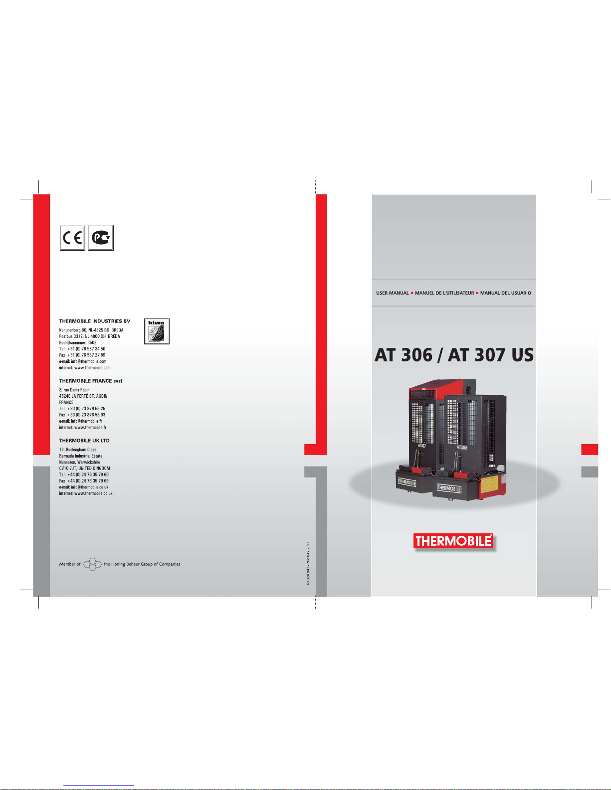
Identification of the product (fig. 1)
The identification plate is attached to the side
of the heater. The identification plate contains
the following data:
A Year of manufacture
B Serial number
C Production code
D Voltage data
E Capacity max (kW)
F Capacity max (MJ/h)
G Type number
Environment
Note
The heater is made of various metals
and synthetic materials. The heater
also contains electronic parts, which
must be treated as electronic waste.
Please contact your dealer for further
information.
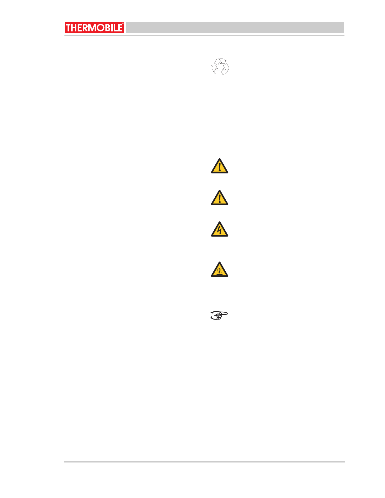
1 SAFETY INSTRUCTIONS
1.1 Pictograms in this manual
Caution
Indicates risk of damage to the
appliance.
Warning
Indicates a dangerous situation, that
can lead to death or serious injuries.
Warning
Always switch off power when
performing maintenance or repairs on
the hot air heater!
Hot
Some surfaces may be hot! Wait until
these parts have sufficiently cooled
down before performing
maintenance.
Service and technical support
Please contact your dealer or the
manufacturer for information about the
heater. Make sure you have the following
Suggestions and tips to simplify the
carrying out of the specified tasks or
actions.
data at hand: type and serial number of the
heater.
1.2 Pictograms on the stationary used
oil fired heater(fig. 2)
Warranty and liability
For warranty and liability, see general
warranty regulations.
A Information about the used oil.
B Positions of the burner: low and high.
C Warning for overheating and switch off.
D Instruction for use.
E Instruction for re-ignition.
AT 300-US series 40.020.941 - rev. 04 - 2011 5
English
1.3 Use this product for its intended
use
The stationary used oil fired hot air heater
has been designed for heating of workshops
at mechanization companies, heating and
frost protection of halls, transit sheds and
warehouses and heating of garage
workshops.
Caution
If the heater will be installed indoors,
make sure that there is proper
ventilation in the room. Make sure the
flue gas can only flow to an outside
source separate from the room.
1.4 General instructions
Warning
• Make sure that the heater is
properly installed, adjusted and
maintained.
• For all service and adjustments
contact qualified, competent and
authorized persons.
• Do not make any modifications to
the heater without the prior
written consent of the
manufacturer.
• Make sure to always follow the
local standards and guidelines as
well as the local requirements,
concerning environmental
quality, fuel, fire and electrical
safety.
• Read this manual carefully
before using the heater.
• Keep this document with the
heater.
• Follow the described procedures.
• Never lean against the heater.
Warning
• Do not create a fire hazard by
storing or using highly
inflammable materials near the
heater. Keep these materials at
adequate distance from the
heater:
- top side 6 inch (150 mm) for
the AT 307
- top side 48 inch (1200 mm)
for the AT 306
- front and sides 36 inch (900
mm)
- back and flue 18 inch (450
mm)
• Make sure there is enough air for
proper combustion.
• Make sure that the convector
heater has cooled down
sufficiently and that the plug has
been removed from the socket
before carrying out any repair or
maintenance work.
1.5 Additional safety
Warning
• Connect the heater only to a
120 V / 60 Hz power supply.
• Replace fuses only with identical
spares.
• The heater must be grounded.
6 40.020.941 - rev. 04 - 2011 AT 300-US series

English
Warning
• Use only the following types of
fuel:
• Automatic transmission oil
• Crankcase oil
•Diesel oil
• Hydraulic oil
• Domestic fuel oil
• Do not add the following
materials to the used oil:
• Anti-freeze
• Carburettor cleaner
• Paint thinner
• Parts washer solvents
• Gasoline
• Transformer oil
• Oil additives
• Any other inappropriate or
hazardous material
• Do not fill the tank while the
heater operates.
2 INTRODUCTION
2.1 Purpose
These stationary used oil heaters are direct
fired heaters with thermal protection and
connections for a flue with rain cap and
optional room thermostat.
The AT 307 is equipped with a hot air fan.
The hot air heaters have been tested at sea
level at a temperature of 68 °F.
2.2 Working principle AT 306
The stationary used oil fired heater is
equipped with an electric motor for driving the
fuel pump.
Diesel oil is poured manually on a burner
dish, which is ignited with a burning paper
pellet. As soon as the burner dish is at the
right temperature, the pump thermostat
activates the fuel pump; the control light
flashes on. The fuel pump pumps the used oil
onto the burner dish. The used oil evaporates
due to the temperature of the burner dish.
The gas vapour burns.
The pump thermostat switches off the fuel
pump when a failure causes the heater to
overheat.
The fuel pump is switched off when the
heater is switched off.
The fuel supply has an overflow that ensures
that the used oil flows back into the fuel tank
when the fuel pipe is blocked.
The overflow protection switches off the fuel
pump when the burner dish overflows.
2.3 Working principle AT 307
The stationary used oil fired heater is
equipped with three electric motors.
The first electric motor drives a fuel pump,
which pumps up the fuel from the fuel tank.
The second electric motor drives the
combustion air fan, which blows the
combustion air into the combustion chamber.
The third electric motor drives the hot air fan,
which extracts the hot air around the
combustion chamber. The hot air is blown
into the space to be heated.
Diesel oil is poured manually on a burner
dish, which is ignited with a burning paper
pellet. As soon as the burner dish is at the
right temperature, the pump thermostat
activates the fuel pump; the control light
flashes on. The fuel pump pumps the used oil
onto the burner dish. The used oil evaporates
due to the temperature of the burner dish.
The gas vapour burns.
The maximum thermostat switches off the
fuel pump when a failure causes the heater to
overheat.
The fuel pump is switched off when the
heater is switched off.
The fan thermostat switches on the motor of
the hot air fan, which causes the hot air to be
blown from the heater into the space to be
heated.
The hot air fan runs until the fan thermostat
switches off the fan: this allows the heater to
cool down.
The fuel supply has an overflow that ensures
that the used oil flows back into the fuel tank
when the fuel pipe is blocked.
AT 300-US series 40.020.941 - rev. 04 - 2011 7

English
The overflow protection switches off the fuel
pump when the burner dish overflows.
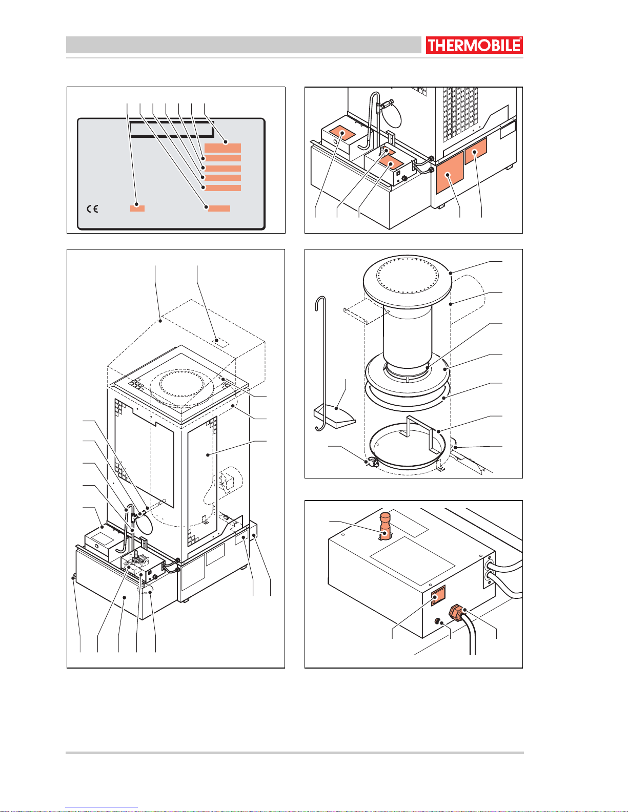
2.4 Main components of the stationary
used oil fired heater (fig. 3)
A Cover
B Flue connection
C Burner
D Connection to hot air fan (optional for AT
306)
E Identification plate
F Fuel filter
G Switch box
H Fuel tank
I Fuel pump
J Drain cock
K Fill filter
L Fuel pipe
M Return line
N Inspection window
O Fuel supply pipe
P For AT 307:
Heat distributor with fan
Q For AT 307:
Maximum thermostat
2.5 Main components burner AT 306
(fig. 4)
A Cover combustion chamber
B Combustion chamber
C Cylinder afterburner
D Upper ring
E Support ring
F Burner dish
G Overflow protection
HKlixon
IShovel
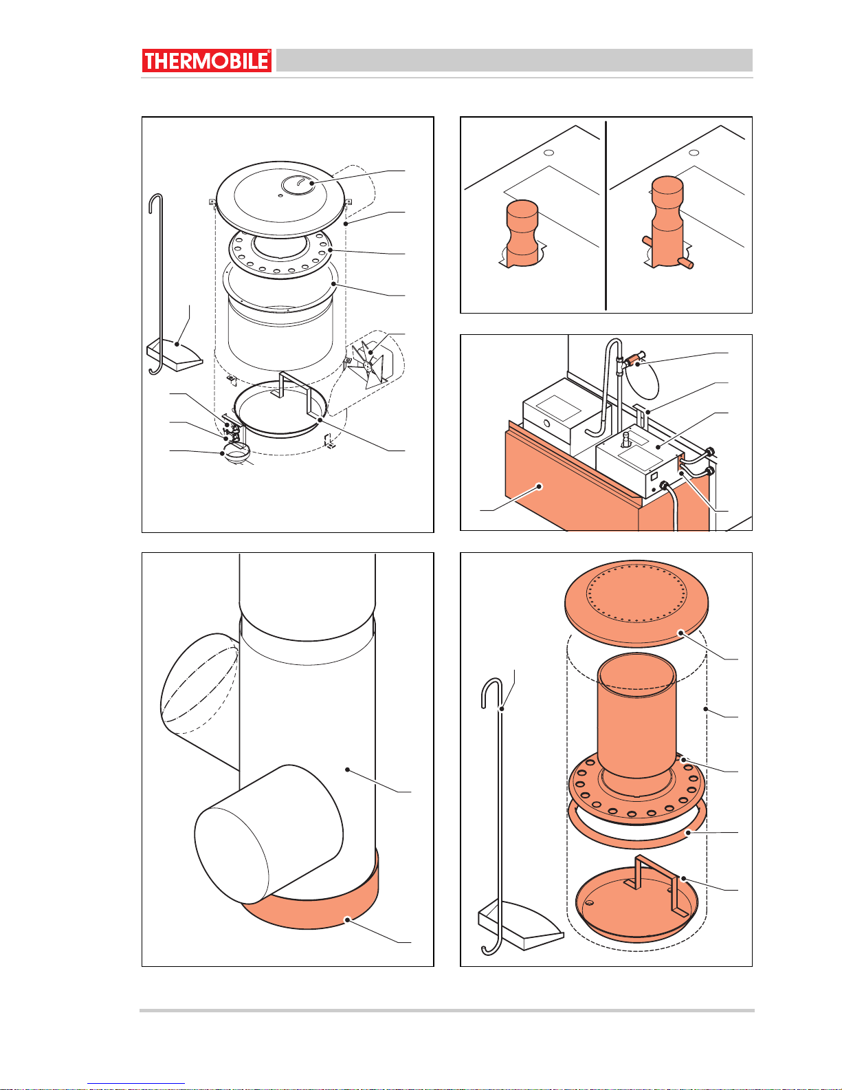
2.6 Main components burner AT 307
(fig. 6)
A Explosion window
B Combustion chamber
C Heat shield
D Vaporisation section
E Combustion air ventilator
F Burner dish
G Overflow protection
H Fan thermostat
I Maximum thermostat
J Shovel
2.7 Switch box (fig. 5)
A Rocker Switch:
- 0: The pump is switched off
- 1: Manual operation
- 2: Automatic mode
B Control light
C Connection cable
D Pump regulator
2.8 Thermostat
THe AT 300 series has the following
thermostats:
• Pump thermostat (for AT 306 and 307):
When the heater is switched to automatic
mode, the fuel pump starts up
automatically when the burner dish
reaches the right temperature.
• Maximum thermostat (for AT 307):
The thermostat stops the fuel pump when
the combustion temperature gets too
high.
• Fan thermostat (for AT 307):
The thermostat starts up the hot air fan
as soon as the heater reaches the right
temperature. After switching off the
heater, the fan thermostat ensures that
the hot air fan keeps running, which cools
the heater. As soon as the heater has
cooled down, the fan thermostat switches
off the hot air fan.
2.9 Accessories
• Flue with rain cap
3 PREPARATIONS
3.1 Removing the packaging
1. Remove packaging from the heater.
2. Remove packaging from the loose parts
in the combustion chamber.
8 40.020.941 - rev. 04 - 2011 AT 300-US series
English
3.2 Installation
1. Ensure that the used oil fired heater is
positioned horizontally.
2. Correctly attach the parts of the
combustion chamber, see fig. 4 and 6.
3. Open the filling cover and fill the tank with
fuel.
Caution
Only the following oil types may be
used in the stationary used oil fired
heaters:
• Automatic transmission oil
•Diesel oil
• Hydraulic oil
• Oil for household use
Note
• Install the equipment in the US
according to the following
publications of the National Fire
Protection Association:
• NFPA #30: Flammable and
Combustible
• Liquids Code
• NFPA #31: Oil Burning
Equipment
• NFPA #88A: Parking
Structures
• NFPA #88B: Repair Garages
• NFPA #211: Chimneys,
Fireplaces and Vents
• Local codes may require that the
heater is mounted at a minimum
of 8 feet (2.4 m) off the ground.
This is especially the case when
there are possible combustible or
flamable fumes in the room.
Refer to NFPA #88B.
• Install the equipment in Canada
according to the following
standard: CSA B139, installation
Code for Oil Burning Equipment.
Place the heater on a location with
respect to the following:
• Possibility of unobstructed, even
heat distribution.
• Safe and easy access for
servicing.
• Unobstructed passage for shop
vehicles and equipment.
• Proper clearances for
combustibles. Refer to the safety
section.
• Adequate combustion air per
local codes. The room must be
ventilated to provide sufficient
combustion-air. The maximum air
consumption is 12 USG/h (46 m
h)
• Proper installation of the stack.
• The structure in which the heater
is located requires the following
minimum dimensions:
• height from the point of
location of the heater: 15 feet
(4.5 m).
• length and width: 20 feet
(6 m).
• floor area: 400 square feet
2
(36 m
)
• Possibility to place the heater on
a combustible flooring.
• If the heater is installed at an
elevation, a permanent platform,
including stairs and railings, must
be provided to facilitate regular
maintenance.
4. Drain condensate from the fuel tank, see
fig. 3 (J).
5. Make sure that the hot air can flow out
freely.
6. Ensure that inflammable materials are at
a sufficient distance from the heater, see
1.4.
7. Ensure there is sufficient ventilation: the
maximum air consumption is 1625 ft
3
/
hour.
8. Make sure there is enough height above
the heater: this needs to be at least 4 ft.
3
/
AT 300-US series 40.020.941 - rev. 04 - 2011 9
English
9. Check the floor surface: this needs to be
2
at least 388 ft
.
10. Install the flue (18 ft and a rain cap).
1 1. Make sure the rocker switch is positioned
at 0.
12. Check the supply voltage: see
identification plate.
13. Place the plug in the socket.
3.3 Preparation for starting up AT 306
1. Switch control of the fuel pump to "low",
see fig. 5 (D).
2. Remove the grate, see fig. 3 (A), the
cover of the combustion chamber,
cylinder afterburner and the upper ring,
see fig. 4 (A, C and D).
3. Check whether the burner dish is clean
and cold.
4. Clean the burner dish and the floor of the
combustion chamber if necessary.
5. Pour 0.2 litre of diesel oil onto the burner
dish, see fig. 4 (F).
Warning
Never pour diesel oil onto a hot
burner dish.
The burner dish must be cool!
6. Re-position the upper ring, the
afterburner and the cylinder.
7. Form a paper pellet and light it.
8. Drop the burning pellet on the burner
dish.
9. Reposition the cover of the combustion
chamber and the grate.
3.4 Preparation for starting up AT 307
1. Switch the control of the fuel pump to
"low", see fig. 5 (D).
2. Push the tank bolt up, see fig. 3 (P).
3. Open the cover of the of the combustion
chamber (fig. 6 A) and open the cover of
the heat shield ( fig. 6 (C).
4. Check whether the burner dish is clean
and cold.
5. Clean the burner dish and the floor of the
combustion chamber if necessary.
6. Pour 0.2 litre of used oil onto the burner
dish, see fig. 6 (F).
Warning
Never pour diesel oil onto a hot
burner dish.
The burner dish must be cool!
7. Form a paper pellet and light it.
8. Drop the burning pellet on the burner
dish.
9. Close the heat shield.
10. Close the heat distributor.
3.5 Starting up
Warning
• Never pour diesel oil onto a hot
burner dish. The burner dish
must be cool and clean!
• Do not start the heater if the fan
still runs. The heater is cooling
down.
• Do not start the heater if excess
oil has accumulated in or near
the heater.
Caution
Do not switch on the convector
heater if there is no fuel, or if the
connected fuel tank is empty.
Caution
Only the following oil types may be
used in the stationary used oil fired
heaters:
• Automatic transmission oil
• Crankcase oil
•Diesel oil
• Hydraulic oil
• Domestic fuel oil
Automatic operation:
1. Switch the rocker switch to "2", see fig. 5
(A).
The combustion air fan starts running
(only with AT 307).
When the burner dish has reached the
right temperature, the fuel pump starts
running and the control light is on.
10 40.020.941 - rev. 04 - 2011 AT 300-US series
English
2. Switch the pump regulator to "low" for the
first 20 to 30 minutes, see fig. 7 (A).
3. Switch the pump regulator to "high" when
the maximum temperature is reached,
see fig. 7 (B).
Manual operation:
1. Wait 5 minutes for the combustion
chamber to reach the right temperature.
2. Switch the rocker switch to "1", see fig. 5
(A).
The fuel pump starts running and the
control light is on.
3. Switch the pump regulator to "low" for the
first 20 to 30 minutes, see fig. 7 (A).
4. Switch the rocker switch to "2" after 20 to
30 minutes.
The pump thermostat starts working.
5. Switch the pump regulator to "high" when
the maximum temperature is reached,
see fig. 7 (B).
4USE
4.1 During operation
Caution
• Do not operate the heater in hot
weather to burn oil.
• Do not burn used oils other than
generated on the premiss of the
owner, unless written
authorization is obtained from the
regulatory authority.
Hot
Do not touch the flue stack or blower
outlet! The flue stack and blower
outlet get hot during operation!
4.2 Switching off
Switch off heating:
5 MAINTENANCE
5.1 Maintenance table
Use the table in this booklet to record
performed maintenance after each winter
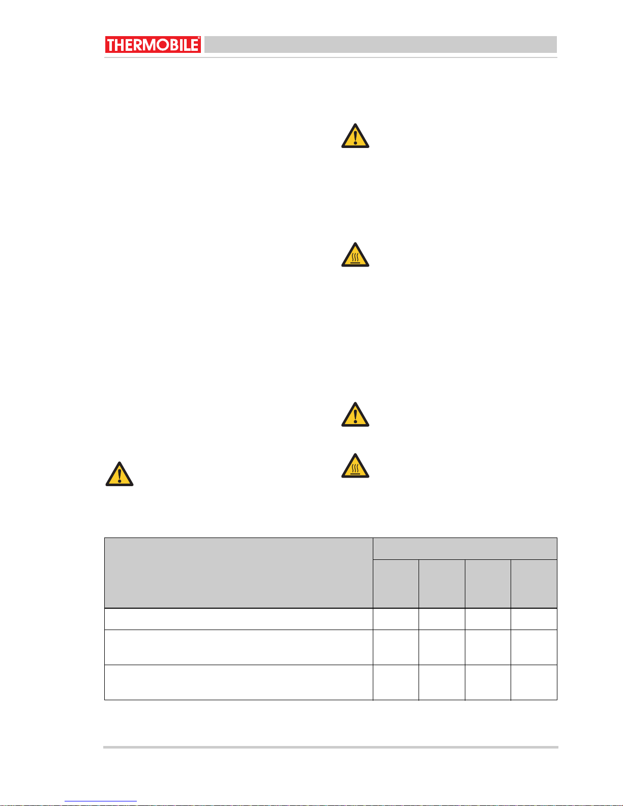
Warning
Always clean the combustion
chamber before starting the heater.
season.
Warning
For all service and adjustments
contact qualified, competent and
authorized persons.
/i
Hot
Do not touch the flue and air outlet!
Wait until the flue and the air outlet
have cooled down sufficiently before
carrying out any maintenance.
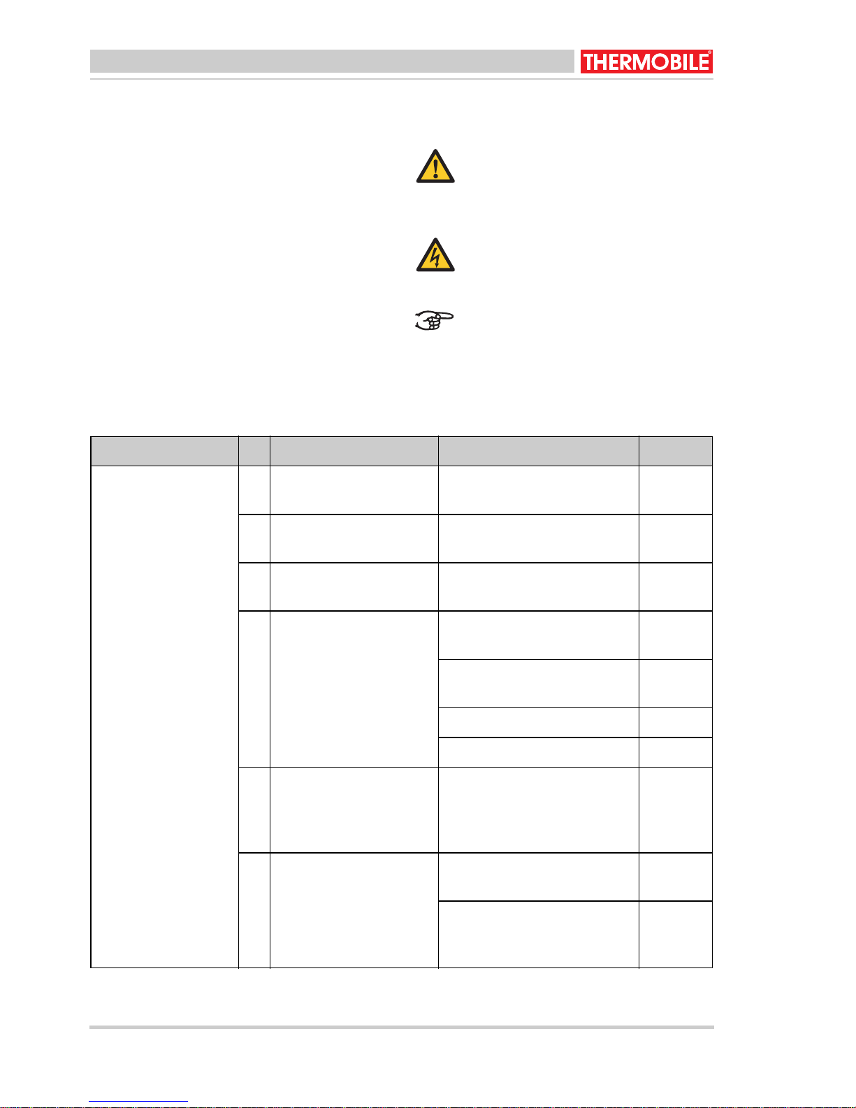
Description Period
Every
12
hours
Clean the combustion chamber. X
Drain (water of) condensation from the fuel tank, when
X
the waste oil contains water.
Weekly MonthlyAnnu-
ally
Only for the AT 307: Clean the combustion chamber
and the vaporiser with a steel brush.
AT 300-US series 40.020.941 - rev. 04 - 2011 11
X

English
Description Period
Every
12
hours
Clean the oil overflow pipe in the floor of the combustion chamber, see fig. 4 (G) for AT 306 and see fig. 6
(G) for AT 307.
Clean the oil supply pipe.
Replace the oil supply pipe when this is burnt out or
damaged.
Check the oil pipes for leakage. X
Clean the fuel tank, the supply filter and the fuel filter.
The fuel tank can easily be removed.
Only for the AT 307: Check the hot air fan and clean if
necessary.
Clean the flue stack valve in the T-piece, see fig. 9 (A).
The recommended draught is 1.5 mmwk (0.06” water
column).
Clean the flue stack T-piece, see "cleaning the flue
stack valve".
Weekly MonthlyAnnu-
ally
X
X
X
X
Dealer
X
Check the heater's wiring. X
Hot
Do not touch the flue stack or
combustion chamber!
Do not perform maintenance until the
flue and combustion chamber have
cooled down.
3. Clean the heater.
4. Use an oily cloth to clean the combustion
chamber, to protect the combustion
chamber against corrosion.
Warning
Do not operate the heater in hot
weather to burn oil.
5.2 General
Warning
Switch off the power supply before
carrying out any repairs!
5.3 Cleaning the combustion chamber
AT 306(fig. 10)
1. Remove the afterburner (A), the cylinder
(C) and the upper ring (D).
When the heater is stored long-term:
1. Switch off the heater.
2. Disconnect the power plug.
2. Clean the parts with a steel brush.
3. Remove the burner dish (E) with the hook
of the shovel (F).
4. Scrape off residues from the burner dish
with a scraper.
12 40.020.941 - rev. 04 - 2011 AT 300-US series

English
5. Clean the inner side of the combustion
chamber (B) with the front of the shovel.
Note
• Used oils can contain heavy
metallic compounds and foreign
materials. These materials stay
as a residu when burned.
Therefore it is necessary to take
care when using, cleaning and
maintaining the heater.
• Wear protective gear when
cleaning the inside of the heater:
• Respirator for fine particles
• Rubber gloves
• Safety goggles
• Protective clothing
• Ensure that the holes in the
combustion chamber wall remain
open for combustion air supply.
6. Remove any soot pieces from the floor of
the combustion chamber.
7. Clean the combustion supply pipe with a
small brush, see fig. 3 (O).
8. Install all parts in reversed order.
The hot air heater can be restarted or shut
down.
5.4 Cleaning the combustion chamber
AT 307(fig. 10)
1. Remove the heat shield (C) and the
upper ring (D).
2. Clean the heat shield and the upper ring
with a steel brush.
3. Remove the burner dish (E) with the hook
of the shovel (F).
4. Clean the burner dish with a scraper.
5. Clean the inner side of the combustion
chamber (B) and the vaporisation
chamber (fig 6.D) with the front of the
shovel.
Note
• Used oils can contain heavy
metallic compounds and foreign
materials. These materials stay
as a residu when burned.
Therefore it is necessary to take
care when using, cleaning and
maintaining the heater.
• Wear protective gear when
cleaning the inside of the heater:
• Respirator for fine particles
• Rubber gloves
• Safety goggles
• Protective clothing
• Ensure that the holes in the
combustion chamber wall remain
open for combustion air supply.
6. Remove any soot pieces from the floor of
the combustion chamber.
7. Clean the fuel supply pipe (O) with a
brush (inner diameter 0.34 inch, see fig.
3.
8. Install all parts in reversed order.
9. Install all parts in reversed order.
5.5 Cleaning the flue stack valve
1. Remove the bottom cover (B) of the Tpiece (A).
2. Clean the flue from top to bottom with a
flue brush.
3. Check the connections for leakage.
4. Check the flue parts for rust.
AT 300-US series 40.020.941 - rev. 04 - 2011 13
Caution
Rust formation indicates that
chlorine containing materials have
been burnt.
Chlorine containing materials
seriously damage the heater. This
may void your warranty.
Contact your dealer for instructions
on how to test waste oil for chlorine.
Reposition the bottom cover.
English
5.6 Remove the fuel tank(fig. 8)
6 FAULTS
1. Remove the fuel supply (A).
2. Take off the connection plate (B).
3. Take plug (C) from the chassis part.
4. Pull up the tank lock (D).
5. Pull the fuel tank (E) from the heater with
Warning
For all service and adjustments
contact qualified, competent and
authorized persons.
care.
6. Install the fuel tank in reversed order.
Warning
Switch off the power supply before
carrying out any repairs!
Ensure that the power is switched on,
and the fuel tank is full, before you
start troubleshooting.
6.1 Troubleshooting table
/i
Fault Cause Solution Action
The flame goes out
directly after ignition.
1 The heater has no volt-
age.
Check the electric connection.
User
2 There is water or sedi-
ment in the fuel tank.
3 The fuel pump is not
switched on.
4 The waste oil is too vis-
cous or too cold.
5 The fuel supply pipe is
blocked: The fuel flows
back into the fuel tank
through the return pipe.
6 The pump thermostat
has not reached the
right temperature yet.
Clean the tank and the fuel
User
filter, see fig. 3 (F).
Position the switch to "1", see
User
fig. 5 (A).
Dilute the waste oil with die-
User
sel oil.
Check the pump thermostat
Dealer
and replace if necessary.
Check the pump motor. Dealer
Check the fuel pump for dirt. Dealer
Clean the fuel supply pipe,
User
see fig. 3 (O).
Let the heater cool down.
User
Restart the heater.
Let the heater burn longer
User
with the switch on "1", see
fig. 5 (A).
14 40.020.941 - rev. 04 - 2011 AT 300-US series

English
Fault Cause Solution Action
The flame goes out
directly after ignition.
6 The pump thermostat
has not reached the
right temperature yet.
7 Only for the AT 307:
The hot air thermostat is
defective.
8 Only for the AT 307:
The combustion air fan
is not functioning.
9 There is insufficient sup-
ply of combustion air
Replace the pump thermostat.
Replace the hot air thermostat.
Check the motor and replace
if necessary.
Only for the AT 306:
Clean the holes in the combustion chamber wall, see
fig. 4 (B).
Only for the AT 307:
Clean the holes in the vaporiser, see fig. 6 (D).
Only for the AT 307:
Check the functioning of the
combustion air fan.
Dealer
Dealer
Dealer
User
User
Dealer
10 There is no proper flue
draught.
11 The flue draught is too
high or irregular.
12 The flue draught is too
low.
Check whether the flue is fit-
User
ted according to the description, see "flue".
Check the flue for leakage. User
Clean the flue if necessary. User
Position a flue stack valve,
Dealer
see "flue".
Adjust the flue to the right
draught (see maintenance
table 5.1) with the counterweight on the valve(fig.9).
Check all connections in the
User
flue.
Reduce the number of
User
bends.
Heighten the flue. User
Isolate the flue outside the
User
building.
AT 300-US series 40.020.941 - rev. 04 - 2011 15
Check the flue, see "flue". User

English
Fault Cause Solution Action
The flame goes out
directly after ignition.
The fuel pump does
not run and the control light is off, while
the heater is preheated and the
switch is switched to
"1" or "2".
13 The maximum thermo-
stat is not installed properly or defective.
14 The overflow protection
is filled with waste oil.
Reset the thermostat, see fig.
3(Q).
Replace the thermostat, see
fig. 3(Q).
For AT 306:
Clean the overflow protection
dish, the burner dish and the
floor of the combustion
chamber.
For AT 307:
Clean the overflow protection
dish, the burner dish and the
floor of the vaporiser.
See faults: 3, 6, and 14.
User
Dealer
User
User
The flame is extinguished while the
fuel pump is still running.
The heater makes a
humming sound.
15 There is too much diesel
oil at start up.
There is soot formation in the combustion chamber and in
the flue.
There is unburnt fuel
on the burner dish.
16 There is too much diesel
oil at start up.
Record the maintenance details in table A in
the appendix of this manual.
See faults: 2, 5, 7, 9, 10 and
12.
Reduce the amount of diesel
oil.
See faults: 10, 11, and 12.
See faults: 8, 9, 10, 11 and
12.
Reduce the amount of diesel
oil.
See faults: 8, 9, 10, 11 and
12.
User
16 40.020.941 - rev. 04 - 2011 AT 300-US series

English
7 SPARE PARTS
Before use we advise you to have spare parts
in store, see table B in the appendix of this
manual.
8 TECHNICAL INFORMATION
• See for technical specifications table C in
the appendix of this manual.
9 INSTALLING ACCESSORIES
9.1 Flue (fig. 9)
The heater has a flue stack connection.
1. Push a T-piece (A) directly over the
connection (B).
2. Push the flue pipe (C) on the T-piece.
3. Use three screws to screw the flue pipe
to the T-piece.
Caution
The flue must meet the following
requirements.
• The flue must be pointed upwards.
• The flue (or any part of it) may not be
positioned horizontally. A 45° angle is
acceptable.
• It is not allowed to lenghten the flue
connection horizontally.
• When a pipe is used under 45°, pipe
pieces of at least 1 m must be fitted in
front of and at the back of the slanting
pipe.
• The flue must stick out at least 0,5 m
above the apex of the building.
• Keep the vertical part at the back of the
heater as long as possible before leading
it outside through the wall.
4. Fit the following pipe pieces.
5. Place a cap (D) at the end of the flue.
9.2 Diameter flue
/i
AT 306 AT 307
5.9 inch 5.9 inch
10 STANDARDS AND GUIDELINES
For the standards and guidelines, go to
www.thermobile.nl.
AT 300-US series 40.020.941 - rev. 04 - 2011 17

English
18 40.020.941 - rev. 04 - 2011 AT 300-US series

Français
Français
Table des matières
Consignes de sécurité .............................. 19
Introduction............................................... 21
Préparations.............................................. 23
Emploi....................................................... 26
Entretien.................................................... 26
Erreurs...................................................... 29
Pièces détachées...................................... 32
Caractéristiques techniques...................... 32
Installation accessoires............................. 33
Normes et directives................................. 33
Avant-propos
Ce manuel contient les instructions
d'utilisation des générateurs présentés en
couverture. Pour une utilisation correcte et
sans risque du générateur, veuillez lire
attentivement les informations de ce manuel.
Identification du produit (fig. 1)
La plaque signalétique est fixée sur le côté
du générateur. Elle indique les données
suivantes :
A Année de fabrication
B Numéro de série
C Code de production
D Données de tension
E Capacité max (kW)
F Capacité max (MJ/h)
G Numéro de type
Maintenance et support technique
Pour obtenir des informations sur le
générateur, veuillez contacter le revendeur
ou le fabricant. Assurez-vous de disposer
des informations suivantes : le type de
générateur et son numéro de série
Environnement
Remarque
Le générateur se compose de
plusieurs métaux et matériaux
synthétiques. Le générateur contient
également des pièces électroniques
qui doivent être traitées comme des
déchets électroniques. Veuillez
contacter votre revendeur pour en
savoir plus.
1 CONSIGNES DE SÉCURITÉ
1.1 Pictogrammes de ce manuel
Précaution
Indique le risque de dommages à la
machine.
Avertissement
Indique une situation dangereuse,
qui peut provoquer la mort ou des
blessures graves.
Avertissement
Toujours couper l'alimentation avant
tout entretien ou réparation sur le
générateur!
Chaud
Certaines surfaces peuvent être
chaudes ! Faire refroidir
suffisamment ces pièces avant tout
action d'entretien.
Suggestions et conseils pour
effectuer plus aisément les tâches ou
activités en question.
Garantie et responsabilité
Pour des conditions de garantie, voir les
conditions générales de garantie.
AT 300-US series 40.020.941 - rev. 04 - 2011 19
1.2 Pictogrammes sur le générateur à
l'huile à utilisation fixe (fig. 2)
A Information sur l'huile utilisée.
B Positions du brûleur : bas et haut.
C Avertissement de surchauffe et coupure.
D Instructions d'utilisation.
E Instructions de rallumage.

Français
1.3 Utilisez ce produit pour son usage
prévu
Le générateur d'air chaud alimenté à l'huile
pour utilisation fixe a été conçu pour le
chauffage des ateliers des sociétés
d'usinage, le chauffage et la protection contre
le gel des halls, zones de transit et entrepôts
et le chauffage des ateliers automobiles.
Précaution
Si le générateur est installé à
l'intérieur, assurez-vous que la pièce
est correctement ventilée. Assurezvous que les gaz de refoulement
peuvent uniquement passer dans une
source externe à la pièce.
1.4 Consignes générales
Avertissement
• Assurez-vous de l'installation, du
réglage et de l'entretien corrects
du générateur.
• Pour tout entretien ou réglage,
contactez des personnes
qualifiées, compétentes et
agréées.
• N'apportez aucune modification
au générateur sans l'accord écrit
préalable du fabricant.
• Assurez-vous de toujours
respecter les normes et
directives locales ainsi que les
obligations locales relatives à
l'environnement, la qualité, les
carburants, les incendies et la
sécurité électrique.
• Lisez attentivement ce manuel
avant d'utiliser le générateur.
• Conservez ce document près du
générateur pour toute utilisation
ultérieure.
• Suivez les procédures décrites.
• Ne vous appuyez jamais contre
le générateur.
Avertissement
• Ne créez aucun risque d'incendie
en stockant ou en utilisant des
matériaux hautement
inflammables à proximité du
générateur. Conservez ces
matériaux à une distance
adéquate du générateur :
- côté supérieur 6 pouce (150
mm) pour l'AT 307
- côté supérieur 48 pouce
(1 200 mm) pour l'AT 306
- avant et côtés 36 pouce (900
mm)
- arrière et tuyau de cheminée
18 pouce (450 mm)
• Veillez à ce qu’il y ait assez d’air
frais pour que la combustion soit
satisfaisante.
• Assurez-vous que le générateur
a refroidi suffisamment et que le
bouchon a été retiré de la douille
avant tout entretien ou
réparation.
20 40.020.941 - rev. 04 - 2011 AT 300-US series

Français
1.5 Sécurité additionnelle
Avertissement
• Connectez le générateur
uniquement à une alimentation
120 V / 60 Hz.
• Remplacez les fusibles
uniquement à l'identique.
• Le générateur doit être mis à la
terre.
Avertissement
• Utilisez uniquement les types de
combustibles suivants :
• Huile transmission
automatique
• Huile de carter
•Diesel
• Huile hydraulique
• Fioul domestique
• N'ajoutez pas les matières
suivantes à l'huile utilisée :
• Antigel
• Nettoyant de carburateur
• Diluant pour peinture
• Solvants de nettoyage de
pièces
• Essence
• Huile de transformation
• Additifs d'huile
• Toute autre matière
dangereuse ou inappropriée
• Ne remplissez pas le rés ervoi r si
le générateur marche.
2 INTRODUCTION
2.1 But
Les générateurs alimentés à l'huile à
utilisation fixe sont des générateurs à
alimentation directe avec protection
thermique et connexions pour un tuyau de
cheminée avec un capuchon anti-pluie et un
thermostat d'ambiance optionnel.
L'AT 307 est équipé d'un ventilateur d'air
chaud.
Les générateurs d'air chaud ont été testés au
niveau de la mer et à une température de
68 °F.
2.2 Principe de fonctionnement de
l'AT 306
Le générateur alimenté à l'huile à utilisation
fixe est équipé d'un moteur électrique
entraînant la pompe à combustible.
Le diesel est versé manuellement dans un
plateau brûleur qui est allumé par une
boulette de papier brûlante. Dès que le
plateau brûleur est à la bonne température,
le thermostat de la pompe active la pompe à
combustible. Le témoin de contrôle s'allume.
La pompe à combustible pompe l'huile
utilisée dans le plateau brûleur. L'huile
utilisée s'évapore en raison de la
température du plateau brûleur. Les vapeurs
gazeuses brûlent.
Le thermostat de la pompe coupe la pompe à
combustible en cas de panne provoquant
une surchauffe du générateur.
La pompe à combustible est coupée lorsque
le générateur est coupé.
L'alimentation en combustible présente un
trop plein qui garantit que l'huile utilisée
retourne dans le réservoir de combustible
lorsque le tuyau de combustible est bouché.
La protection de trop plein coupe la pompe à
combustible lorsque le plateau brûleur
déborde.
2.3 Principe de fonctionnement de
l'AT 307
Les générateurs alimentés à l'huile à
utilisation fixe sont équipés de trois moteurs
électriques.
Le premier moteur électrique entraîne une
pompe à combustible qui pompe le
combustible du réservoir de combustible.
Le second moteur électrique entraîne le
ventilateur d'air de combustion qui souffle l'air
de combustion dans la chambre de
combustion.
Le troisième moteur électrique entraîne le
ventilateur d'air chaud qui extrait l'air chaud
de la partie autour de la chambre de
combustion. L'air chaud est soufflé dans
l'espace à chauffer.
AT 300-US series 40.020.941 - rev. 04 - 2011 21

Français
Le diesel est versé manuellement dans un
plateau brûleur qui est allumé par une
boulette de papier brûlante. Dès que le
plateau brûleur est à la bonne température,
le thermostat de la pompe active la pompe à
combustible. Le témoin de contrôle s'allume.
La pompe à combustible pompe l'huile
utilisée dans le plateau brûleur. L'huile
utilisée s'évapore en raison de la
température du plateau brûleur. Les vapeurs
gazeuses brûlent.
Le thermostat de maximum coupe la pompe
à combustible en cas de panne provoquant
une surchauffe du générateur.
La pompe à combustible est coupée lorsque
le générateur est coupé.
Le thermostat du ventilateur enclenche le
moteur du ventilateur d'air chaud qui est ainsi
soufflé du générateur dans l'espace à
chauffer.
Le ventilateur d'air chaud fonctionne jusqu'à
ce que son thermostat l'arrête : le générateur
peut ainsi refroidir.
L'alimentation en combustible présente un
trop plein qui garantit que l'huile utilisée
retourne dans le réservoir de combustible
lorsque le tuyau de combustible est bouché.
La protection de trop plein coupe la pompe à
combustible lorsque le plateau brûleur
déborde.
2.4 Principaux composants des
générateurs alimentés à l'huile à
utilisation fixe (fig. 3)
A Cache
B Tuyau de cheminée
CBrûleur
D Connexion à ventilateur d'air chaud
(optionnelle pour AT 306)
E Plaque signalétique
F Filtre à combustible
G Boîtier d'interrupteurs
H Réservoir de combustible
I Pompe à combustible
J Robinet de purge
K Filtre de remplissage
L Tuyau de combustible
M Conduite de retour
N Jauge d'inspection
O Tuyau d'alimentation en combustible
P Pour AT 307 :
Distributeur de chaleur avec ventilateur
Q Pour AT 307 :
Thermostat maximum
2.5 Principaux composants de brûleur
AT 306 (fig. 4)
A Cache chambre de combustion
B Chambre de combustion
C Cylindre postcombustion
D Bague supérieure
E Bague de support
F Plateau brûleur
G Protection de trop plein
HKlixon
IPelle
2.6 Principaux composants de brûleur
AT 307 (fig. 6)
A Fenêtre d'explosion
B Chambre de combustion
C Écran thermique
D Section de vaporisation
E Ventilateur d'air de combustion
F Plateau brûleur
G Protection de trop plein
H Thermostat ventilateur
IThermostat maximum
JPelle
2.7 Boîtier d'interrupteurs (fig. 5)
A Interrupteur à bascule :
- 0: La pompe est arrêtée
- 1: Fonctionnement manuel
- 2: Mode automatique
B Témoin de contrôle
C Câble de connexion
D Régulateur de pompe
22 40.020.941 - rev. 04 - 2011 AT 300-US series

Français
2.8 Thermostat
La série AT 300 dispose des thermostats
suivants :
• Thermostat de pompe (pour AT 306 et
307) :
Lorsque le générateur est en mode
automatique, la pompe à combustible
s'enclenche automatiquement dès que le
plateau brûleur atteint la température
correcte.
• Thermostat maximum (pour AT 307) :
Le thermostat coupe la pompe à
combustible lorsque la température de
combustion est trop élevée.
• Thermostat de ventilateur (pour AT 307) :
Le thermostat lance le ventilateur d'air
chaud dès que le générateur atteint la
température correcte. Une fois le
générateur coupé, le thermostat du
ventilateur assure que le ventilateur d'air
chaud continue de tourner, ce qui refroidit
le générateur. Dès que le générateur a
refroidi, le thermostat de ventilateur
coupe le ventilateur d'air chaud.
2.9 Accessoires
• Tuyau de cheminée avec capuchon antipluie
3PRÉPARATIONS
3.1 Retrait de l’emballage
1. Enlevez l’emballage du générateur.
2. Retirez l'emballage des pièces libres de
la chambre de combustion.
3.2 Installation
1. Assurez-vous que le générateur alimenté
à l'huile utilisée est positionné
horizontalement.
2. Fixez correctement les pièces de la
chambre de combustion, voir fig. 4 et 6.
3. Ouvrez le cache de remplissage et
remplissez le réservoir de combustible.
Précaution
Seuls les types de combustibles
suivants peuvent être utilisés avec
les générateurs alimentés à l'huile à
utilisation fixe :
• Huile transmission automatique
•Diesel
• Huile hydraulique
• Huile à usage domestique
Remarque
• Installez l'équipement aux ÉtatsUnis selon les publications
suivantes de la National Fire
Protection Association :
• NFPA #30: Flammable and
Combustible Liquids Code
• NFPA #31: Oil Burning
Equipment
• NFPA #88A: Parking
Structures
• NFPA #88B: Repair Garages
• NFPA #211: Chimneys,
Fireplaces and Vents
• Les codes locaux peuvent exiger
le montage du générateur à un
minimum de 8 pied (2.4 m) du
sol. C'est spécialement le cas si
la pièce peut contenir des
fumées combustibles ou
inflammables. Voir NFPA #88B.
• Installez l'équipement au Canada
selon les normes suivantes :
CAN B139, Code d'installation
pour équipement de combustion
d'huile.
AT 300-US series 40.020.941 - rev. 04 - 2011 23

Français
Placez le générateur dans un endroit
respectant les conditions suivantes :
• Possibilité d'une distribution
uniforme et libre de la chaleur.
• Accès sécurisé et facile pour
l'entretien.
• Passage libre pour les véhicules
et équipement d'atelier.
• Distance adaptée des
combustibles. Voir la section
Sécurité.
• Air de combustion adéquat selon
les codes locaux. La pièce doit
être ventilée afin de fournir
suffisamment d'air de
combustion. La consommation
maximum d'air est de 12 USG/h
3
(46 m
/h).
• Installation correcte du tuyau.
• La structure dans laquelle le
générateur se trouve doit
présenter les dimensions
minimum suivantes :
• hauteur depuis le point
d'emplacement du
générateur : 15 pied (4.5 m).
• longueur et largeur : 20 pied
(6 m).
• surface au sol : 400 pied
carré (36 m
2
)
• Possibilité de placer le
générateur sur un sol
combustible.
• Si le générateur est installé en
hauteur, une plate-forme
permanente, incluant des
escaliers ou des rampes, doit
être prévue pour faciliter
l'entretien régulier.
4. Purgez le condensat du réservoir de
combustible, voir fig. 3 (J).
5. Veillez également à ce que le flux d’air
réchauffé ne soit pas obstrué.
6. Assurez-vous que les matériaux
inflammable sont suffisamment éloignés
du générateur, voir 1.4.
7. Assurez-vous que la ventilation soit
suffisante : la consommation maximum
d'air est de 1625 ft
3
/h
8. Assurez-vous du dégagement suffisant
en hauteur au-dessus du générateur :
elle doit mesurer au moins 4 ft.
9. Vérifiez la surface au sol : elle doit
mesurer au moins 388 ft
2
.
10. Installez le tuyau de cheminée (18 ft de
long et un capuchon anti-pluie)
1 1. Assurez-vous que l'interrupteur à bascule
est sur 0.
12. Vérifiez la tension d’alimentation : pour
cela, consulter la plaque signalétique.
13. Branchez la prise électrique.
3.3 Préparation au démarrage de l'AT
306
1. Positionnez la commande de pompe à
combustible sur "bas", voir fig. 5 (D).
2. Retirez la grille, voir fig. 3 (A), le cache de
la chambre de combustion, le cylindre de
postcombustion et la bague supérieure,
voir fig. 4 (A, C et D).
3. Vérifiez si le plateau brûleur est propre et
froid.
4. Nettoyez le plateau brûleur et le fond de
la chambre de combustion, si nécessaire.
5. Versez 0,2 litre de diesel sur le plateau
brûleur, voir fig. 4 (F).
Avertissement
Ne versez jamais le diesel sur un
plateau brûleur chaud.
Le plateau brûleur doit être froid !
6. Repositionnez la bague supérieure, la
postcombustion et le cylindre.
7. Formez une boulette de papier et
allumez-la.
8. Jetez la boulette de papier brûlante sur le
plateau brûleur.
9. Repositionnez le cache de la chambre de
combustion et la grille.
24 40.020.941 - rev. 04 - 2011 AT 300-US series

Français
3.4 Préparation au démarrage de l'AT
307
1. Positionnez la commande de pompe à
combustible sur "bas", voir fig. 5 (D).
2. Poussez le boulon du réservoir vers le
haut, voir fig. 3 (P).
3. Ouvrez le cache de la chambre de
combustion (fig. 6 A) et le cache de
l'écran thermique ( fig. 6 (C).
4. Vérifiez si le plateau brûleur est propre et
froid.
5. Nettoyez le plateau brûleur et le fond de
la chambre de combustion, si nécessaire.
6. Versez 0,2 litre de l'huile utilisée sur le
plateau brûleur, voir fig. 6 (F).
Avertissement
Ne versez jamais le diesel sur un
plateau brûleur chaud.
Le plateau brûleur doit être froid !
7. Formez une boulette de papier et
allumez-la.
8. Jetez la boulette de papier brûlante sur le
plateau brûleur.
9. Fermez l'écran thermique.
10. Fermez le distributeur de chaleur.
3.5 Démarrage
Avertissement
• Ne versez jamais le diesel sur un
plateau brûleur chaud. Le
plateau brûleur doit être froid et
propre !
• Ne démarrez pas le générateur
si le ventilateur tourne encore. Le
générateur refroidit.
• Ne démarrez pas le générateur
si l'huile s'est excessivement
accumulée dans le générateur
ou à proximité.
Précaution
Ne mettez pas le générateur en
marche en l'absence de combustible
ou si le réservoir de combustible
connecté est vide.
Précaution
Seuls les types de combustibles
suivants peuvent être utilisés avec
les générateurs alimentés à l'huile à
utilisation fixe :
• Huile transmission automatique
• Huile de carter
•Diesel
• Huile hydraulique
• Fioul domestique
Fonctionnement automatique :
1. Positionnez l'interrupteur à bascule sur
"2", voir fig. 5 (A).
Le ventilateur d'air de combustion se met
en marche (uniquement avec AT 307).
Lorsque le plateau brûleur a atteint la
bonne température, la pompe à
combustible se met en marche et le
témoin de contrôle s'allume.
2. Positionnez le régulateur de la pompe
sur "bas" pendant les 20 à 30 premières
minutes, voir fig. 7 (A).
3. Positionnez le régulateur de la pompe
sur "haut" lorsque la température
maximum est atteinte, voir fig. 7 (B).
AT 300-US series 40.020.941 - rev. 04 - 2011 25

Français
Fonctionnement manuel :
1. Attendez 5 minutes pour que la chambre
de combustion atteigne la température
correcte.
2. Positionnez l'interrupteur à bascule sur
"1", voir fig. 5 (A).
La pompe à combustible démarre et le
témoin de contrôle s'allume.
3. Positionnez le régulateur de la pompe
sur "bas" pendant les 20 à 30 premières
minutes, voir fig. 7 (A).
4. Positionnez l'interrupteur à bascule sur
"2" après 20 à 30 minutes.
Le thermostat de pompe se déclenche.
5. Positionnez le régulateur de la pompe
sur "haut" lorsque la température
maximum est atteinte, voir fig. 7 (B).
5 ENTRETIEN
4EMPLOI
4.1 Au cours du fonctionnement
Précaution
• N'utilisez pas le générateur par
temps chaud pour brûler de
l'huile.
• Ne brûlez aucune huile usée
exceptée celle générée sur le
site du propriétaire, sauf
autorisation écrite de l'autorité
régulatoire.
Chaud
Ne touchez pas au tuyau de
cheminée ni à la sortie d'air ! Le
tuyau de cheminée et la sortie d'air
deviennent chauds pendant le
fonctionnement!
5.1 Tableau d’entretien
Utilisez le tableau dans ce manuel pour
enregistrer l'entretien effectué après chaque
saison d'hiver.
Avertissement
Pour tout entretien ou réglage,
contactez des personnes qualifiées,
compétentes et agréées.
Avertissement
Nettoyez toujours la chambre de
combustion avant de démarrer le
générateur.
Chaud
Ne touchez ni au tuyau de cheminée
ni à la sortie d’air !
Attendez que le tuyau de cheminée
et la sortie d'air aient suffisamment
refroidi avant d'effectuer tout
entretien.
/i
Description Fréquence
Toutes
les 12
heures
Nettoyez la chambre de combustion. X
Purgez la condensation (l'eau) du réservoir de com-
X
bustible si le déchet d'huile contient de l'eau.
Hebdomadaire
Mensuel
Annuel
26 40.020.941 - rev. 04 - 2011 AT 300-US series

Description Fréquence
Français
Toutes
les 12
heures
Uniquement pour l'AT 307 : Nettoyez la chambre de
combustion et le vaporisateur avec une brosse à dents.
Nettoyez le tuyau de trop plein d'huile au fond de la
chambre de combustion, voir fig. 4 (G) pour l'A T 306 et
fig. 6 (G) pour l'AT 307.
Nettoyez le tuyau d'alimentation en huile.
Remplacez le tuyau d'alimentation en huile s'il est brûlé
ou endommagé.
Vérifiez si les tuyaux d'huile présentent une fuite. X
Nettoyez le réservoir de combustible, le filtre d'alimen-
tation et le filtre à combustible.
Le réservoir à combustible est facilement amovible.
Uniquement pour l'AT 307 : Contrôlez le ventilateur
d'air chaud et nettoyez-le au besoin.
Nettoyez la vanne de tuyau de cheminée dans la pièce
en T, voir fig. 9 (A).
Le tirage recommandé est de 1,5 mmwk (0.06” de
colonne d'eau).
Hebdomadaire
X
X
X
Mensuel
X
X
Revendeur
Annuel
Nettoyez la pièce en T du tuyau de cheminée, voir "nettoyage de la vanne de tuyau de cheminée".
Vérifiez le câblage du générateur. X
Chaud
Ne touchez pas au tuyau de
cheminée ni à la chambre de
combustion !
N'effectuez aucun entretien tant que
le tuyau de cheminée et la chambre
de combustion n'ont pas refroidi.
1. Éteignez le générateur.
2. Débranchez la prise d'alimentation.
3. Nettoyez le générateur.
4. Utilisez un chiffon huileux pour nettoyer
la chambre de combustion afin de la
protéger de la corrosion.
Avertissement
N'utilisez pas le générateur par
5.2 Général
temps chaud pour brûler de l'huile.
Avertissement
Coupez l'alimentation électrique
avant toute réparation !
Si le générateur est stocké pendant une
période prolongée :
X
AT 300-US series 40.020.941 - rev. 04 - 2011 27

Français
5.3 Nettoyage de la chambre de
combustion AT 306(fig. 10)
1. Retirez la postcombustion (A), le cylindre
(C) et la bague supérieure (D).
2. Nettoyez les pièces avec une brosse
d'acier.
3. Retirez le plateau brûleur (E) avec le
crochet de la pelle (F).
4. Grattez les résidus du plateau brûleur
avec un grattoir.
5. Nettoyez l'intérieur de la chambre de
combustion (B) avec l'avant de la pelle.
Remarque
• Les huiles utilisées peuvent
contenir des composés
métalliques et des substances
étrangères. Ces matières restent
sous forme de résidus une fois
brûlées. Il est donc nécessaire de
faire attention en utilisant, en
nettoyant et en entretenant le
générateur.
• Portez un équipement de
protection pour nettoyer
l'intérieur du générateur :
• Respirateur pour particules
fines
• Gants en caoutchouc
• Lunettes de sécurité
• Vêtements de protection
• Assurez-vous que tous les
orifices de la chambre de
combustion restent ouverts pour
alimenter la combustion en air.
6. Retirez toute trace de suie du fond de la
chambre de combustion.
7. Nettoyez le tuyau d'alimentation en
combustible avec une petite brosse, voir
fig. 3 (O).
8. Installez les pièces en ordre inverse.
Le générateur d'air chaud peut être
redémarré ou arrêté.
5.4 Nettoyage de la chambre de
combustion AT 307(fig. 10)
1. Retirez l'écran thermique (C) et la bague
supérieure (D).
2. Nettoyez l'écran thermique et la bague
supérieure avec une brosse en acier.
3. Retirez le plateau brûleur (E) avec le
crochet de la pelle (F).
4. Nettoyez le plateau brûleur avec un
grattoir.
5. Nettoyez l'intérieur des chambres de
combustion (B) et de vaporisation (fig
6.D) avec l'avant de la pelle.
Remarque
• Les huiles utilisées peuvent
contenir des composés
métalliques et des substances
étrangères. Ces matières restent
sous forme de résidus une fois
brûlées. Il est donc nécessaire de
faire attention en utilisant, en
nettoyant et en entretenant le
générateur.
• Portez un équipement de
protection pour nettoyer
l'intérieur du générateur :
• Respirateur pour particules
fines
• Gants en caoutchouc
• Lunettes de sécurité
• Vêtements de protection
• Assurez-vous que tous les
orifices de la chambre de
combustion restent ouverts pour
alimenter la combustion en air.
6. Retirez toute trace de suie du fond de la
chambre de combustion.
7. Nettoyez la conduite alimentation en
combustible (O) avec une brosse
(diamètre d'intérieur de 0.34 pouce), voir
fig. 3.
8. Installez les pièces en ordre inverse.
9. Installez les pièces en ordre inverse.
28 40.020.941 - rev. 04 - 2011 AT 300-US series

Français
5.5 Nettoyage de la vanne de tuyau de
cheminée
1. Retirez le cache du fond (B) de la pièce
en T (A).
2. Nettoyez le tuyau de cheminée du fond
avec un hérisson.
3. Vérifiez si les connexions fuient.
4. Vérifiez si les pièces du tuyau de
cheminée présentent des traces de
rouille.
Précaution
La formation de rouille indique que
des matériaux contenant du chlore
ont été brûlés.
Les matériaux contenant du chlore
peuvent endommager gravement le
générateur. Votre garantie peut être
annulée.
Contactez votre revendeur pour en
savoir plus sur le moyen de tester la
présence de chlore dans l'huile de
rebut.
5.6 Retirez le réservoir de
combustible (fig. 8)
1. Retirez l'alimentation de combustible (A).
2. Retirez la plaque de connexion (B).
3. Retirez le bouchon (C) de la partie
châssis.
4. Retirez le bouchon du réservoir (D).
5. Retirez le réservoir à combustible (E) du
générateur avec soin.
6. Installez le réservoir à combustible en
ordre inverse.
6 ERREURS
Avertissement
Pour tout entretien ou réglage,
contactez des personnes qualifiées,
compétentes et agréées.
Avertissement
Coupez l'alimentation électrique
avant toute réparation !
Repositionnez le cache du fond.
Assurez-vous que l'alimentation
électrique est activée et que le
réservoir à combustible est plein
avant de commencer le dépannage.
6.1 Tableau de dépannage
/i
Défaillance Cause Solution Action
La flamme s'éteint
directement après
l'allumage.
1 Le générateur n'est pas
sous tension.
2 Présence d'eau ou de
sédiment dans le réservoir à combustible.
3 La pompe à combustible
n'est pas allumée.
4 L'huile de rebut est trop
visqueuse ou froide.
Vérifier le branchement électrique.
Nettoyez le réservoir et le filtre à combustible, voir fig. 3
(F).
Positionnez l'interrupteur sur
"1", voir fig. 5 (A).
Diluez l'huile de rebut avec
du diesel.
Vérifiez le thermostat de
pompe et remplacez-le au
Utilisateur
Utilisateur
Utilisateur
Utilisateur
Revendeur
besoin.
AT 300-US series 40.020.941 - rev. 04 - 2011 29

Français
Défaillance Cause Solution Action
La flamme s'éteint
directement après
l'allumage.
4 L'huile de rebut est trop
visqueuse ou froide.
5 Le tuyau d'alimentation
en combustible est bouché : le combustible
retourne dans son
réservoir via le tuyau de
retour.
6 Le thermostat de pompe
n'a pas encore atteint la
bonne température.
Vérifiez le moteur de pompe. Reven-
deur
Vérifiez si la pompe à combustible contient de la pous-
Revendeur
sière.
Nettoyez le tuyau d'alimenta-
Utilisateur
tion en combustible, voir fig.
3 (O).
Laissez le générateur refroi-
Utilisateur
dir.
Redémarrez le générateur.
Laissez le générateur brûler
Utilisateur
plus longtemps avec l'interrupteur sur "1", voir fig. 5 (A).
Remplacez le thermostat de
pompe.
Reven-
deur
7 Uniquement pour l'AT
307 :
Le thermostat d'air
chaud est défectueux.
8 Uniquement pour l'AT
307 :
Le ventilateur d'air de
combustion ne fonctionne pas.
9 L'alimentation d'air de
combustion est insuffisante.
Remplacez le thermostat
d'air chaud.
Vérifiez et remplacez le
moteur si nécessaire.
Uniquement pour l'AT 306 :
Nettoyez les orifices de la
paroi de la chambre de combustion, voir fig. 4 (B).
Uniquement pour l'AT 307 :
Nettoyez les orifices du
vaporisateur, voir fig. 6 (D).
Uniquement pour l'AT 307 :
Vérifiez le fonctionnement du
ventilateur d'air de combustion.
Reven-
deur
Reven-
deur
Utilisateur
Utilisateur
Reven-
deur
30 40.020.941 - rev. 04 - 2011 AT 300-US series

Français
Défaillance Cause Solution Action
La flamme s'éteint
directement après
l'allumage.
10 Le tirage du tuyau de
cheminée n'est pas bon.
11 Le tuyau de cheminée
est trop haut ou irrégulier.
12 Le tirage du tuyau de
cheminée est trop faible.
Vérifiez si le tuyau de cheminée est raccordé selon la
description, voir "tuyau de
cheminée".
Vérifiez si le tuyau de cheminée fuit.
Nettoyez le tuyau de cheminée au besoin.
Positionnez une vanne de
tuyau de cheminée, voir
"tuyau de cheminée".
Ajustez le tuyau de cheminée
selon un tirage correct (voir
le tableau d'entretien 5.1)
avec le contrepoids sur la
vanne (fig. 9)
Vérifiez toutes les connexions du tuyau de cheminée.
Utilisateur
Utilisateur
Utilisateur
Revendeur
Utilisateur
13 Le thermostat maxi-
mum est mal installé ou
défectueux.
14 La protection de trop
plein est remplie d'huile
de rebut.
Réduisez le nombre de coudes.
Relevez le tuyau de cheminée.
Isolez le tuyau de cheminée
à l'extérieur du bâtiment.
Vérifiez le tuyau de cheminée, voir "tuyau de cheminée".
Réajustez le thermostat, voir
fig. 3 (Q).
Remplacez le thermostat,
voir fig. 3 (Q).
Pour AT 306 :
Nettoyez le plateau de la protection de trop plein, le plateau brûleur et le fond de la
chambre de combustion.
Utilisateur
Utilisateur
Utilisateur
Utilisateur
Utilisateur
Revendeur
Utilisateur
AT 300-US series 40.020.941 - rev. 04 - 2011 31

Français
Défaillance Cause Solution Action
La flamme s'éteint
directement après
l'allumage.
La pompe à combustible ne fonctionne
pas et le témoin de
contrôle est éteint
alors que le générateur est préchauffé et
que l'interrupteur est
sur "1" ou "2".
La flamme est
éteinte alors que la
pompe à combustible fonctionne
encore.
Le générateur émet
un bourdonnement.
14 La protection de trop
plein est remplie d'huile
de rebut.
15 Il y a trop de diesel au
démarrage.
Pour AT 307 :
Nettoyez le plateau de la protection de trop plein, le plateau brûleur et le fond du
vaporisateur.
Voir défaillances : 3, 6 et 14.
Voir défaillances : 2, 5, 7, 9,
10 et 12.
Réduisez la quantité de diesel.
Utilisateur
Utilisateur
De la suie se forme
dans la chambre de
combustion et le
tuyau de cheminée.
Le plateau brûleur
contient du combus-
16 Il y a trop de diesel au
démarrage.
tible non brûlé.
Conservez les informations d'entretien dans
le tableau A qui se trouve en annexe de ce
manuel.
7 PIÈCES DÉTACHÉES
Il est recommandé de toujours disposer de
pièces détachées en stock: voir tableau B en
annexe de ce manuel.
Voir défaillances : 10, 11 et
12.
Voir défaillances : 8, 9, 10, 11
et 12.
Réduisez la quantité de diesel.
Voir défaillances : 8, 9, 10, 11
et 12.
8 CARACTÉRISTIQUES
TECHNIQUES
• Pour des spécifications techniques, voir
le tableau C dans l'annexe de ce manuel.
32 40.020.941 - rev. 04 - 2011 AT 300-US series

9 INSTALLATION ACCESSOIRES
9.1 Tuyau de cheminée (fig. 9)
Le générateur comporte une connexion pour
le tuyau de cheminée.
1. Poussez une pièce en T (A) directement
sur la connexion (B).
2. Poussez le tuyau de cheminée (C) sur la
pièce en T.
3. Utilisez trois vis pour fixer le tuyau de
cheminée sur la pièce en T.
Précaution
Le tuyau de cheminée doit respecter
les impératifs suivants.
• Le tuyau de cheminée doit être dirigé
vers le haut.
• Le tuyau de cheminée (ou une de ses
parties) ne peut être positionné à
l'horizontale. Un angle de 45° est
acceptable.
• Il n'est pas permis d'allonger le raccord
de tuyau de cheminée à l'horizontale.
• Si un tuyau est utilisé à 45°, les pièces de
tuyau d'au moins 3.3 ft doivent être
montées à l'avant et à l'arrière du tuyau
incliné.
• Le tuyau de cheminée doit dépasser d'au
moins 1.6 ft au dessus du bâtiment.
• Maintenez la partie verticale à l'arrière du
générateur aussi longue que possible
avant de la faire passer à l'extérieur dans
le mur.
4. Fixez les pièces de tuyau suivantes.
5. Placez un capuchon (D) à l’extrémité du
tuyau.
Français
9.2 Diamètre tuyau cheminée
/i
AT 306 AT 307
5.9 pouce 5.9 pouce
10 NORMES ET DIRECTIVES
Pour les normes et directives, rendez-vous
sur le site www.thermobile.nl.
AT 300-US series 40.020.941 - rev. 04 - 2011 33
Español
Español
Índice
Instrucciones de seguridad........................34
Introducción...............................................36
Preparaciones............................................38
Uso ............................................................41
Mantenimiento...........................................42
Fallos.........................................................45
Piezas de repuesto....................................49
Información técnica....................................49
Instalación de accesorios ..........................50
Normas y directivas...................................50
Prólogo
Este manual contiene las instrucciones de
uso de los generadores de aire caliente que
se muestran en la portada. La información de
este manual es importante para el uso
correcto y seguro del generador.
Identificación del producto (fig. 1)
La placa de identificación está fijada en el
lateral del generador. En la placa de
identificación figuran los siguientes datos:
A Año de fabricación
B Número de serie
C Código de fabricación
D Datos sobre tensión
E Capacidad máx. (kW)
F Capacidad máx. (MJ/h)
G Número de modelo
Medio ambiente
Nota
El generador de aire caliente está
fabricado de diversos materiales
metálicos y sintéticos. El generador
también contiene componentes
electrónicos, que tienen que tratarse
como desechos electrónicos.
Póngase en contacto con su
distribuidor para obtener más
información.
1 INSTRUCCIONES DE SEGURIDAD
1.1 Símbolos utilizados en este
manual
Precaución
Indica un riesgo de daños en el
aparato.
Advertencia
Indica una situación peligrosa, que
puede provocar la muerte o lesiones
graves.
Advertencia
¡Desconecte siempre la alimentación
eléctrica cuando realice trabajos de
mantenimiento o reparaciones en el
generador de aire caliente!
Servicio y asistencia técnica
Póngase en contacto con su distribuidor o
con el fabricante para obtener información
sobre el generador de aire caliente.
Asegúrese de tener a mano los siguientes
datos: el modelo y el número de serie del
generador.
Garantía y responsabilidad
Consulte los términos de garantía y
responsabilidad en las reglas generales de
garantía.
34 40.020.941 - rev. 04 - 2011 AT 300-US series
Caliente
¡Algunas superficies pueden estar
calientes! Espere hasta que estos
componentes se hayan enfriado lo
suficiente antes de realizar el
mantenimiento.
Sugerencias y consejos para
simplificar la realización de las tareas
o acciones especificadas.

Español
1.2 Símbolos en el generador de uso
estacionario que utiliza aceite (fig.
2)
A Información sobre el aceite utilizado.
B Posiciones del quemador: baja y alta.
C Advertencia de sobrecalentamiento y
desconexión.
D Instrucciones de uso.
E Instrucciones de reencendido.
1.3 Utilice este producto para su uso
previsto
El generador de aire caliente de uso
estacionario que utiliza aceite se ha diseñado
para el calentamiento de talleres en
empresas de mecanizado, el calentamiento y
protección antihielo de salas, naves de
tránsito y almacenes y para el calentamiento
de talleres mecánicos.
Precaución
Si va a instalar el generador de aire
caliente por convección en el interior,
asegúrese de que haya la suficiente
ventilación en el recinto. Asegúrese
de que los gases de la chimenea
puedan salir únicamente a una fuente
exterior independiente del recinto.
1.4 Instrucciones generales
Advertencia
• Asegúrese de que el generador
esté correctamente instalado,
ajustado y mantenido.
• Para todos los ajustes y tareas
de mantenimiento, póngase en
contacto con personal con la
debida formación, competencia y
autorización.
• No realice modificaciones al
generador sin el previo
consentimiento por escrito del
fabricante.
Advertencia
• Asegúrese de seguir siempre las
normativas y directivas locales,
así como los requisitos relativos
a la calidad medioambiental y a
la seguridad eléctrica,
antiincendios y de combustible.
• Lea este manual detenidamente
antes de utilizar el generador.
• Mantenga este documento con el
generador.
• Siga los procedimientos
descritos.
• No se apoye nunca en el
generador.
• No provoque un riesgo de
incendio almacenando o
utilizando materiales altamente
inflamables cerca del generador.
Mantenga estos materiales a una
distancia adecuada del
generador:
- lado superior 6 pulgada (150
mm) para el AT 307
- lado superior 48 pulgada
(1200 mm) para el AT 306
- frente y laterales 36 pulgada
(900 mm)
- parte posterior y chimenea
18 pulgada (450 mm)
• Asegúrese de que haya
suficiente aire fresco para
garantizar una correcta
combustión.
• Asegúrese de que el generador
de aire caliente por convección
se haya enfriado lo suficiente y
de que se haya quitado el
enchufe de la toma de corriente
antes de realizar trabajos de
reparación o mantenimiento.
AT 300-US series 40.020.941 - rev. 04 - 2011 35

Español
1.5 Seguridad adicional
Advertencia
• Conecte el generador
únicamente a un suministro de
alimentación de 120 V / 60 Hz.
• Sustituya los fusibles por
repuestos idénticos.
• El generador debe conectarse a
tierra.
Advertencia
• Utilice únicamente los siguientes
tipos de combustible:
• Aceite para transmisión
automática
• Aceite para el cárter del
cigüeñal
• Gasóleo
• Aceite hidráulico
• Fuel-oil doméstico
• No añada los siguientes
materiales al aceite usado:
• Anticongelante
• Limpiador de carburador
• Diluyente de pinturas
• Disolventes de limpieza de
componentes
• Gasolina
• Aceite para transformador
• Aditivos de aceite
• Cualquier otro material
inadecuado o peligroso
• No llene el depósito mientras el
generador esté en
funcionamiento.
2 INTRODUCCIÓN
2.1 Objetivo
Estos generadores de uso estacionario que
utilizan aceite son generadores de
combustión directa con protección térmica y
conexiones para una chimenea con cubierta
para lluvia y un termostato en el recinto
opcional.
El A T 307 está equipado con un ventilador de
aire caliente.
Los generadores de aire caliente se han
probado a nivel del mar y a una temperatura
de 68 °F.
2.2 Principio de funcionamiento del
AT 306
El generador de uso estacionario que utiliza
aceite está equipado con un motor eléctrico
para accionar la bomba de combustible.
El gasóleo se vierte manualmente en un
plato quemador, que se inflama con un
gránulo de papel ardiendo. En cuanto el plato
quemador alcanza la temperatura adecuada,
el termostato de la bomba activa la bomba de
combustible; la luz de control parpadea y se
enciende. La bomba de combustible bombea
el aceite utilizado en el plato quemador. El
aceite utilizado se evapora debido a la
temperatura del plato quemador. El vapor de
gas arde.
El termostato de la bomba desconecta la
bomba de combustible cuando un fallo hace
que el generador se sobrecaliente.
La bomba de combustible se desconecta
cuando se desconecta el generador.
El suministro de combustible tiene un
rebosadero que garantiza que el aceite
utilizado regrese al depósito de combustible
cuando se obstruye el conducto de
combustible.
La protección de rebosamiento desconecta la
bomba de combustible cuando el plato
quemador rebosa.
2.3 Principio de funcionamiento del
AT 307
El generador de uso estacionario que utiliza
aceite está equipado con tres motores
eléctricos.
El primer motor eléctrico acciona una bomba
de combustible, que bombea el combustible
desde el depósito.
El segundo motor eléctrico acciona el
ventilador de aire de combustión, que aporta
aire de combustión a la cámara de
combustión.
36 40.020.941 - rev. 04 - 2011 AT 300-US series

Español
El tercer motor eléctrico acciona el ventilador
de aire caliente, que extrae el aire caliente
alrededor de la cámara de combustión. El
aire caliente se desprende en el espacio que
desea calentarse.
El gasóleo se vierte manualmente en un
plato quemador, que se inflama con un
gránulo de papel ardiendo. En cuanto el plato
quemador alcanza la temperatura adecuada,
el termostato de la bomba activa la bomba de
combustible; la luz de control parpadea y se
enciende. La bomba de combustible bombea
el aceite utilizado en el plato quemador. El
aceite utilizado se evapora debido a la
temperatura del plato quemador. El vapor de
gas arde.
El termostato máximo desconecta la bomba
de combustible cuando un fallo hace que el
generador se sobrecaliente.
La bomba de combustible se desconecta
cuando se desconecta el generador.
El termostato del ventilador conecta el motor
del ventilador de aire caliente, que hace que
se desprenda el aire caliente del generador
en el espacio que se desea calentar.
El ventilador de aire caliente funciona hasta
que el termostato lo desconecta: esto
permite que el generador se enfríe.
El suministro de combustible tiene un
rebosadero que garantiza que el aceite
utilizado regrese al depósito de combustible
cuando se obstruye el conducto de
combustible.
La protección de rebosamiento desconecta la
bomba de combustible cuando el plato
quemador rebosa.
2.4 Principales componentes del
generador de uso estacionario que
utiliza aceite (fig. 3)
A Cubierta
B Conexión de la chimenea
C Quemador
D Conexión para el ventilador de aire
caliente (opcional para AT 306)
E Placa de identificación
F Filtro de combustible
G Caja de conmutación
H Depósito de combustible
I Bomba de combustible
J Llave de drenaje
K Filtro de llenado
L Conducto de combustible
M Conducto de retorno
N Ventana de inspección
O Conducto de suministro de combustible
P Para AT 307:
Distribuidor de calor con ventilador
Q Para AT 307:
Termostato máximo
2.5 Principales componentes del
quemador del AT 306 (fig. 4)
A Cubierta cámara de combustión
B Cámara de combustión
C Postquemador del cilindro
D Anillo superior
E Anillo de soporte
F Plato quemador
G Protección de rebosamiento
H Klixon
IPala
2.6 Principales componentes del
quemador del AT 307 (fig. 6)
A Ventana de explosión
B Cámara de combustión
C Escudo térmico
D Sección de vaporización
E Ventilador de aire de combustión
F Plato quemador
G Protección de rebosamiento
H Termostato del ventilador
I Termostato máximo
JPala
2.7 Caja de conmutación (fig. 5)
A Interruptor basculante:
- 0: la bomba está apagada
- 1: Funcionamiento manual
- 2: Modo automático
B Luz de control
C Cable de conexión
D Regulador de la bomba
AT 300-US series 40.020.941 - rev. 04 - 2011 37

Español
2.8 Termostato
La serie AT 300 tiene los siguientes
termostatos:
• Termostato de la bomba (para AT 306 y
307):
Cuando el generador pasa a modo
automático, la bomba de combustible
arranca automáticamente cuando el
plato quemador alcanza la temperatura
adecuada.
• Termostato máximo (para AT 307):
El termostato detiene la bomba de
combustible cuando la temperatura sube
demasiado.
• Termostato del ventilador (para AT 307):
El termostato arranca el ventilador de
aire caliente en cuanto el generador
alcanza la temperatura correcta. Tras
desconectar el generador, el termostato
del ventilador garantiza que el ventilador
de aire caliente siga funcionando, lo cual
refrigera el generador. Cuando el
generador se ha enfriado, el termostato
del ventilador desconecta el ventilador de
aire caliente.
2.9 Accesorios
• Chimenea con cubierta para lluvia
3 PREPARACIONES
3.1 Desembalaje
1. Retire el embalaje del generador.
2. Retire el embalaje de las piezas sueltas
en la cámara de combustión.
3.2 Instalación
1. Asegúrese de que el generador que
utiliza aceite esté colocado
horizontalmente.
2. Conecte correctamente los componentes
de la cámara de combustión, véanse las
figs. 4 y 6.
3. Abra la tapa de llenado y llene el
depósito de combustible.
Precaución
Sólo pueden utilizarse los siguientes
aceites en los generadores de uso
estacionario que utilizan aceite:
• Aceite para transmisión
automática
• Gasóleo
• Aceite hidráulico
• Aceite doméstico
Nota
• Instale el equipo en los EE.UU.
de acuerdo a las siguientes
publicaciones de la National Fire
Protection Association
(Asociación nacional de
protección contra incendios):
• NFPA #30: Flammable and
Combustible Liquids Code
(Código de líquidos
inflamables y combustibles)
• NFPA #31: Oil Burning
Equipment (Equipos de
quemado de aceite)
• NFPA #88A: Parking
Structures (Estructuras de
aparcamiento)
• NFPA #88B: Repair Garages
(Garajes de reparación)
• NFPA #211: Chimneys,
Fireplaces and Vents
(Chimeneas, hogares y
ventilaciones)
• Los códigos locales pueden
requerir que el generador se
monte a un mínimo de 2,4 m del
suelo. Esto es especialmente el
caso cuando existe la posibilidad
de vapores combustibles o
inflamables en el recinto.
Consulte NFPA #88B.
38 40.020.941 - rev. 04 - 2011 AT 300-US series

Español
Nota
• Instale el equipo en Canadá de
acuerdo a la siguiente norma:
CSA B139, installation Code for
Oil Burning Equipment (Código
de instalación para equipos de
quemado de aceite).
Coloque el generador en un lugar
con respecto a lo siguiente:
• Posibilidad de distribución sin
obstáculos y uniforme del calor.
• Acceso seguro y fácil para
reparaciones y mantenimiento.
• Paso sin obstáculos para
vehículos y equipos de taller.
• Espacio libre adecuado para
combustibles. Consulte la
sección de seguridad.
• Aire de combustión adecuado
según los códigos locales. El
recinto debe estar ventilado para
proporcionar el suficiente aire de
combustión. El consumo máximo
de aire es 12 USG/h (46 m
3
/h)
• Instalación correcta de la
chimenea.
• La estructura en la que se sitúa
el generador requiere las
siguientes dimensiones mínimas:
• altura desde el punto de
situación del generador: 15
pie (4.5 m).
• longitud y anchura: 20 pie
(6 m).
• superficie en suelo: 400 pie
cuadrado (36 m
2
)
• Posibilidad de colocar el
generador sobre un suelo
combustible.
• Si el generador está instalado en
una elevación, debe contarse
con una plataforma permanente,
incluyendo escaleras y rejas,
para facilitar el mantenimiento
regular.
4. Drene el condensado del depósito de
combustible, véase la fig. 3 (J).
5. Asegúrese de que el aire caliente pueda
fluir libremente.
AT 300-US series 40.020.941 - rev. 04 - 2011 39

Español
6. Asegúrese de que los materiales
inflamables se encuentren a la distancia
suficiente del generador, véase 1.4.
7. Asegúrese de que haya la suficiente
ventilación: el consumo máximo de aire
es 1625 ft
3
/hora.
8. Asegúrese de que haya suficiente altura
sobre el generador: debe ser al menos 4
ft.
9. Compruebe la superficie del suelo: debe
ser al menos 388 ft
2
.
10. Monte la chimenea (18 ft y una tapa para
lluvia).
11. Asegúrese de que el interruptor
basculante esté en la posición 0.
12. Compruebe la tensión de alimentación:
consulte la placa de identificación.
13. Inserte la clavija en la toma de corriente.
3.3 Preparación para la puesta en
marcha del AT 306
1. Sitúe el control de la bomba de
combustible en "low" (bajo), véase la fig.
5 (D).
2. Retire la rejilla, véase la fig. 3 (A), la
cubierta de la cámara de combustión, el
postquemador del cilindro y el anillo
superior fig. 4 (A, C y D).
3. Compruebe si el plato quemador está
limpio y frío.
4. Limpie el plato quemador y el suelo de la
cámara de combustión en caso
necesario.
5. Vierta 0,2 litros de gasóleo en el plato
quemador, véase la fig. 4 (F).
3.4 Preparación para la puesta en
marcha del AT 307
1. Sitúe el control de la bomba de
combustible en "low" (bajo), véase la fig.
5 (D).
2. Empuje hacia arriba el perno del
depósito, véase la fig. 3 (P).
3. Abra la cubierta de la cámara de
combustión (fig. 6 A) y abra la cubierta
del escudo térmico (fig. 6 C).
4. Compruebe si el plato quemador está
limpio y frío.
5. Limpie el plato quemador y el suelo de la
cámara de combustión en caso
necesario.
6. Vierta 0,2 litros del aceite utilizado en el
plato quemador, véase la fig. 6 (F).
Advertencia
Nunca vierta gasóleo en un plato
quemador caliente.
¡El plato quemador debe estar frío!
7. Forme un gránulo de papel y enciéndalo.
8. Deje caer el gránulo ardiendo en el plato
quemador.
9. Cierre el escudo térmico.
10. Cierre el distribuidor de calor.
Advertencia
Nunca vierta gasóleo en un plato
quemador caliente.
¡El plato quemador debe estar frío!
6. Vuelva a colocar el anillo superior, el
postquemador y el cilindro.
7. Forme un gránulo de papel y enciéndalo.
8. Deje caer el gránulo ardiendo en el plato
quemador.
9. Vuelva a colocar la cubierta de la cámara
de combustión y la rejilla.
40 40.020.941 - rev. 04 - 2011 AT 300-US series

Español
3.5 Puesta en marcha
Advertencia
• Nunca vierta gasóleo en un plato
quemador caliente. ¡El plato
quemador debe estar frío y
limpio!
• No ponga en marcha el
generador si el ventilador aún
funciona. El generador se está
enfriando.
• No ponga en marcha el
generador si se ha acumulado
un exceso de aceite dentro o
cerca del generador.
Precaución
No conecte el generador de aire
caliente por convección si no hay
combustible o si el depósito de
combustible conectado está vacío.
Precaución
Sólo pueden utilizarse los siguientes
aceites en los generadores de uso
estacionario que utilizan aceite:
• Aceite para transmisión
automática
• Aceite para el cárter del cigüeñal
• Gasóleo
• Aceite hidráulico
• Fuel-oil doméstico
Funcionamiento automático:
1. Sitúe el interruptor basculante en "2",
véase la fig. 5 (A).
El ventilador de aire de combustión
empieza a funcionar (sólo con AT 307).
Cuando el plato quemador haya
alcanzado la temperatura adecuada, la
bomba de combustible empieza a
funcionar y la luz de control se enciende.
2. Sitúe el regulador de la bomba en "low"
(bajo) durante los primeros 20 a 30
minutos, véase la fig. 7 (A).
3. Sitúe el regulador de la bomba en "high"
(alto) cuando se alcance la temperatura
máxima, véase la fig. 7 (B).
Funcionamiento manual:
1. Espere 5 minutos para que la cámara de
combustión alcance la temperatura
correcta.
2. Sitúe el interruptor basculante en "1",
véase la fig. 5 (A).
La bomba de combustible empieza a
funcionar y la luz de control se enciende.
3. Sitúe el regulador de la bomba en "low"
(bajo) durante los primeros 20 a 30
minutos, véase la fig. 7 (A).
4. Sitúe el interruptor basculante en "2"
después de entre 20 a 30 minutos.
El termostato de la bomba empieza a
funcionar.
5. Sitúe el regulador de la bomba en "high"
(alto) cuando se alcance la temperatura
máxima, véase la fig. 7 (B).
4USO
4.1 Durante el funcionamiento
Precaución
• No haga funcionar el generador
para quemar aceite cuando haga
mucho calor.
• No queme aceites usados
distintos a los generados en el
local del propietario, a menos
que se obtenga autorización por
escrito de la autoridad
reguladora.
Caliente
¡No toque la chimenea ni la salida del
soplador! ¡La chimenea y la salida
del soplador se calientan durante el
funcionamiento!
AT 300-US series 40.020.941 - rev. 04 - 2011 41

Español
4.2 Desconexión
Desconexión del calentador:
1. Sitúe el interruptor basculante en "0".
La bomba de combustible deja de
funcionar.
La luz de control se apaga.
Precaución
Sólo para el AT 307:
Tras el apagado, el ventilador
distribuidor de calor sigue
funcionando. Este ventilador
refrigera el generador hasta que se
haya enfriado lo suficiente (tras 10 a
30 minutos).
El ventilador de aire de combustión
funciona mientras funcione el
ventilador distribuidor de calor.
5 MANTENIMIENTO
5.1 Tabla de mantenimiento
Utilice la tabla incluida en este manual para
registrar las operaciones de mantenimiento
llevadas a cabo después de cada temporada
Advertencia
Limpie siempre la cámara de
combustión antes de arrancar el
generador.
de invierno.
Advertencia
Para todos los ajustes y tareas de
mantenimiento, póngase en contacto
con personal con la debida
formación, competencia y
autorización.
/i
Caliente
¡No toque la chimenea ni la salida de
aire!
Espere hasta que la chimenea y la
salida de aire se hayan enfriado lo
suficiente antes de realizar tareas de
mantenimiento.
Descripción Período
Cada
12 horas
Limpie la cámara de combustión. X
Semanal
Mensu-alAnual
Drene la condensación (agua) del depósito de combustible, cuando el aceite de desecho contenga agua.
Sólo para el A T 307: Limpie la cámara de combustión y
el vaporizador con un cepillo de acero.
42 40.020.941 - rev. 04 - 2011 AT 300-US series
X
X

Descripción Período
Español
Cada
12 horas
Limpie el conducto de rebosamiento de aceite del
suelo de la cámara de combustión, véase la fig. 4 (G)
para AT 306 y la fig. 6 (G) para AT 307.
Limpie el conducto del suministro de aceite.
Sustituya el conducto de suministro de aceite cuando
éste esté quemado o dañado.
Compruebe si hay fugas en los conductos de aceite. X
Limpie el depósito de combustible, el filtro de suminis-
tro y el filtro de combustible.
El depósito de combustible puede retirarse fácilmente.
Sólo para el AT 307: Compruebe el ventilador de aire
caliente y limpie en caso necesario.
Limpie la válvula de la chimenea en la pieza en T,
véase la fig. 9 (A).
El tiro recomendado es 1.5 mmwk (0.06” de columna
de agua).
Semanal
X
X
Mensu-alAnual
X
X
Distribuidor
Limpie la pieza en T de la chimenea, consulte "Limpieza de la válvula de la chimenea".
Compruebe el cableado del generador. X
Caliente
¡No toque la chimenea ni la cámara
de combustión!
No realice el mantenimiento hasta
que la chimenea y la cámara de
combustión se hayan enfriado.
3. Limpie el generador.
4. Utilice un paño impregnado de aceite
para limpiar la cámara de combustión y
protegerla contra la corrosión.
Advertencia
No haga funcionar el generador para
quemar aceite cuando haga mucho
5.2 Aspectos generales
calor.
Advertencia
¡Desconecte el suministro de
alimentación antes de realizar
reparaciones!
5.3 Limpieza de la cámara de
combustión AT 306(fig. 10)
1. Retire el postquemador (A), el cilindro
(C) y el anillo superior (D).
Cuando almacene el generador durante un
periodo prolongado:
1. Apague el generador.
2. Desenchufe la clavija de alimentación.
2. Limpie los componentes con un cepillo
de acero.
3. Retire el plato quemador (E) con el
gancho de la pala (F).
X
AT 300-US series 40.020.941 - rev. 04 - 2011 43

Español
4. Rasque los residuos del plato quemador
con un rascador.
5. Limpie el interior de la cámara de
combustión (B) con el frente de la pala.
Nota
• Los aceites usados pueden
contener compuestos metálicos
pesados y materiales extraños.
Estos materiales permanecen
como residuos cuando se
queman. Por tanto, es necesario
tener cuidado al utilizar, limpiar y
realizar el mantenimiento del
generador.
• Lleve equipos de protección
cuando limpie el interior del
generador:
• Respirador para partículas
de pequeño tamaño
• Guantes de goma
• Gafas de seguridad
• Ropa de protección
• Asegúrese de que los orificios de
la cámara de combustión
permanezcan abiertos para el
suministro de aire de
combustión.
5. Limpie el interior de la cámara de
combustión (B) y la cámara de
vaporización (fig. 6 D) con el frente de la
pala.
Nota
• Los aceites usados pueden
contener compuestos metálicos
pesados y materiales extraños.
Estos materiales permanecen
como residuos cuando se
queman. Por tanto, es necesario
tener cuidado al utilizar, limpiar y
realizar el mantenimiento del
generador.
• Lleve equipos de protección
cuando limpie el interior del
generador:
• Respirador para partículas
de pequeño tamaño
• Guantes de goma
• Gafas de seguridad
• Ropa de protección
• Asegúrese de que los orificios de
la cámara de combustión
permanezcan abiertos para el
suministro de aire de
combustión.
6. Retire el hollín del suelo de la cámara de
combustión.
7. Limpie el conducto de suministro de
combustión con un cepillo pequeño,
véase la fig. 3 (O).
8. Instale todos los componentes en orden
inverso.
El generador de aire caliente puede
restablecerse o apagarse.
5.4 Limpieza de la cámara de
combustión AT 307(fig. 10)
1. Retire el escudo térmico (C) y el anillo
superior (D).
2. Limpie el escudo térmico y el anillo
superior con un cepillo de acero.
3. Retire el plato quemador (E) con el
gancho de la pala (F).
4. Limpie el plato quemador con un
rascador.
6. Retire el hollín del suelo de la cámara de
combustión.
7. Limpie el tubo de suministro de
combustible (O) con un cepillo (diámetro
interno 0.34 pulgada), véase la fig. 3.
8. Instale todos los componentes en orden
inverso.
9. Instale todos los componentes en orden
inverso.
44 40.020.941 - rev. 04 - 2011 AT 300-US series
Español
5.5 Limpieza de la válvula de la
chimenea
1. Retire la cubierta inferior (B) de la pieza
en T (A).
2. Limpie la chimenea de arriba a abajo con
un cepillo para chimeneas.
3. Compruebe si hay fugas en las
conexiones.
4. Compruebe si los componentes de la
chimenea presentan óxido.
Precaución
La formación de óxido indica que se
han quemado materiales con
contenido de cloro.
Los materiales con contenido de
cloro pueden dañar gravemente el
generador. Su utilización puede
anular la garantía.
Póngase en contacto con su
distribuidor para saber cómo
comprobar si hay cloro en el aceite
de desecho.
Vuelva a colocar la cubierta inferior.
3. Quite el tapón (C) de la parte del chasis.
4. Tire hacia arriba del cierre del depósito
(D).
5. Separe el depósito de combustible (E)
del generador con cuidado.
6. Instale el depósito de combustible en
orden inverso.
6FALLOS
Advertencia
Para todos los ajustes y tareas de
mantenimiento, póngase en contacto
con personal con la debida formación,
competencia y autorización.
Advertencia
¡Desconecte el suministro de
alimentación antes de realizar
reparaciones!
Asegúrese de que la alimentación
eléctrica se conecte y que el depósito
de combustible esté lleno antes de
iniciar la localización de averías.
5.6 Retirada del depósito de
combustible (fig. 8)
1. Retire el suministro de combustible (A).
2. Saque la placa de conexión (B).
6.1 Tabla de localización de averías
AT 300-US series 40.020.941 - rev. 04 - 2011 45

Español
/i
Fallo Causa Solución Acción
La llama se apaga
directamente tras el
encendido.
1 El generador no tiene
tensión.
2 Hay agua o sedimentos
en el depósito de combustible.
3 La bomba de combusti-
ble no se conecta.
4 El aceite de desecho
está demasiado viscoso o frío.
5 El conducto de suminis-
tro de combustible está
obstruido: el combustible regresa al depósito
de combustible por el
conducto de retorno.
Compruebe la conexión eléctrica.
Limpie el depósito y el filtro
de combustible, véase la fig.
3 (F).
Sitúe el interruptor en "1",
véase la fig. 5 (A).
Diluya el aceite de desecho
con gasóleo.
Compruebe el termostato de
la bomba y sustituya en caso
necesario.
Compruebe el motor de la
bomba.
Compruebe si hay suciedad
en la bomba de combustible.
Limpie el conducto de suministro de combustible, véase
la fig. 3 (O).
Usuario
Usuario
Usuario
Usuario
Distribuidor
Distribuidor
Distribuidor
Usuario
46 40.020.941 - rev. 04 - 2011 AT 300-US series

Español
Fallo Causa Solución Acción
La llama se apaga
directamente tras el
encendido.
6 El termostato de la
bomba aún no ha alcanzado la temperatura
correcta.
7 Sólo para el AT 307:
El termostato de aire
caliente está defectuoso.
8 Sólo para el AT 307:
El ventilador de aire de
combustión no funciona.
9 No hay suficiente sumi-
nistro de aire de combustión
Deje que el generador se
enfríe.
Restablezca el generador.
Deje que el generador
queme más tiempo con el
interruptor en "1", véase la
fig. 5 (A).
Sustituya el termostato de la
bomba.
Sustituya el termostato de
aire caliente.
Compruebe el motor y sustituya en caso necesario.
Sólo para el AT 306:
Limpie los orificios de la
pared de la cámara de combustión, véase la fig. 4 (B).
Usuario
Usuario
Distribuidor
Distribuidor
Distribuidor
Usuario
10 No hay un tiro adecuado
de la chimenea.
Sólo para el AT 307:
Limpie los orificios del vaporizador, véase la fig. 6 (D).
Sólo para el AT 307:
Compruebe el funcionamiento del ventilador de aire
de combustión.
Compruebe si la chimenea
se ha fijado según la descripción, consulte "Chimenea".
Compruebe si hay fugas en
la chimenea.
Limpie la chimenea en caso
necesario.
Usuario
Distribuidor
Usuario
Usuario
Usuario
AT 300-US series 40.020.941 - rev. 04 - 2011 47
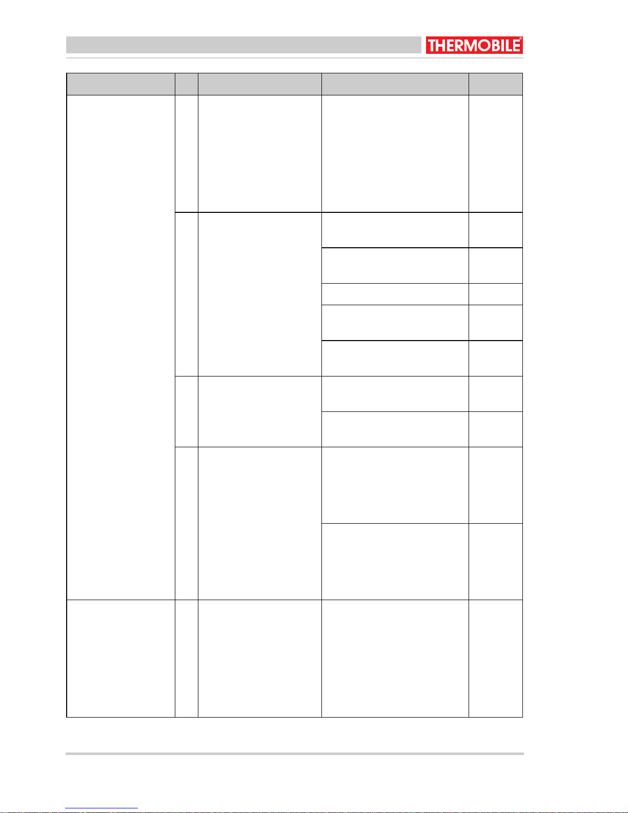
Español
Fallo Causa Solución Acción
La llama se apaga
directamente tras el
encendido.
1 1 El tiro de la chimenea es
demasiado elevado o
irregular.
12 El tiro de la chimenea es
demasiado bajo.
13 El termostato máximo
no está instalado
correctamente o es
defectuoso.
Coloque una válvula en la
chimenea, consulte "Chime-
Distribui-
dor
nea".
Ajuste la chimenea al tiro
correcto (consulte la tabla de
mantenimiento 5.1) con el
contrapeso de la válvula (fig.
9)
Compruebe todas las
Usuario
conexiones de la chimenea.
Reduzca el número de
Usuario
codos.
Aumente la chimenea. Usuario
Aísle la chimenea en el exte-
Usuario
rior del edificio.
Compruebe la chimenea,
Usuario
véase "Chimenea".
Restablezca el termostato,
Usuario
véase la fig. 3 (Q).
Sustituya el termostato,
véase la fig. 3 (Q).
Distribui-
dor
La bomba de combustible no funciona
y la luz de control
está apagada, mientras el generador se
precalienta y el interruptor se sitúa en
"1" ó "2".
14 La protección de rebo-
samiento se llena de
aceite de desecho.
Para AT 306:
Limpie el plato de protección
de rebosamiento, el plato
quemador y el suelo de la
cámara de combustión.
Para AT 307:
Limpie el plato de protección
de rebosamiento, el plato
quemador y el suelo del
vaporizador.
Consulte los fallos: 3, 6 y 14.
Usuario
Usuario
48 40.020.941 - rev. 04 - 2011 AT 300-US series

Español
Fallo Causa Solución Acción
La llama se apaga
mientras la bomba
de combustible aún
funciona.
El generador emite
un zumbido.
15 Hay demasiado gasó-
leo en el arranque.
Hay formación de
hollín en la cámara
de combustión y en
la chimenea.
Hay combustible sin
quemar en el plato
16 Hay demasiado gasó-
leo en el arranque.
quemador.
Registre los detalles de mantenimiento en la
tabla A en el apéndice que se incluye en este
manual.
Consulte los fallos: 2, 5, 7, 9,
10 y 12.
Reduzca la cantidad de
gasóleo.
Consulte los fallos: 10, 11 y
12.
Consulte los fallos: 8, 9, 10,
11 y 12.
Reduzca la cantidad de
gasóleo.
Consulte los fallos: 8, 9, 10,
11 y 12.
Usuario
7 PIEZAS DE REPUESTO
Antes de utilizar el aparato, le
recomendamos que disponga siempre de
piezas de repuesto. Consulte la tabla B en el
apéndice que se incluye en este manual.
8 INFORMACIÓN TÉCNICA
• Consulte las especificaciones técnicas
en la tabla C en el apéndice que se
incluye en este manual.
AT 300-US series 40.020.941 - rev. 04 - 2011 49

Español
9 INSTALACIÓN DE ACCESORIOS
9.1 Chimenea
El generador tiene una conexión de
chimenea.
1. Introduzca una pieza en T (A)
directamente en la conexión (B).
2. Introduzca el tubo de la chimenea (C) en
la pieza en T.
3. Utilice tres tornillos para atornillar el tubo
de la chimenea a la pieza en T.
Precaución
La chimenea debe cumplir los
siguientes requisitos.
• La chimenea debe estar orientada hacia
arriba.
• La chimenea (o cualquier parte de ella)
no puede colocarse horizontalmente. Un
ángulo de 45° es aceptable.
• No se permite alargar la conexión de la
chimenea horizontalmente.
• Cuando se usa un tubo por debajo de
45°, las piezas del tubo de al menos 1 m
deben colocarse delante y detrás del
tubo inclinado.
• La chimenea debe sobresalir al menos
0,5 m sobre el punto más alto del edificio.
• Mantenga la parte vertical en la parte
posterior del generador, en la medida de
lo posible, antes de llevarla hacia el
exterior a través de la pared.
4. Acople las siguientes piezas de tubo.
5. Acople una cubierta (D) en el extremo de
la chimenea.
9.2 Diámetro de chimenea
/i
AT 306 AT 307
5.9 inch 5.9 inch
10 NORMAS Y DIRECTIVAS
Para las normas y directrices, vaya a
www.thermobile.nl.
50 40.020.941 - rev. 04 - 2011 AT 300-US series

/i
A
Date Description: Maintenance or Failure Action by
Date Description: Entretien ou Erreur Action par
Fecha Descripcíon Mantenimiento o fallo Accíon por
AT 300-US series 40.020.941 - rev. 04 - 2011 49

Date Description: Maintenance or Failure Action by
Date Description: Entretien ou Erreur Action par
Fecha Descripcíon Mantenimiento o fallo Accíon por
50 40.020.941 - rev. 04 - 2011 AT 300-US series

B
A
/i
A Combustion scale
Échelle de combustion
Plato de combustión
AT 306 AT 307
41.900.521 41.900.521
AT 300-US series 40.020.941 - rev. 04 - 2011 51

/i
C
AT 306 AT 307
Minimum Gross capacity *
Capacité brute minimum
Capacidad bruta mínima
Maximum Gross capacity *
Capacité brute maximum
Capacidad bruta máxima
Minimum fuel consumption
Consommation de
combustible minimum
Consumo de combustible
mínimo
Maximum fuel consumption
Consommation de
combustible maximum
Consumo de combustible
máximo
Minimum combustion time
with full tank
Durée de combustion
minimum avec réservoir plein
Tiempo de combustión
mínimo con depósito lleno
BTU/h
kW
BTU/h
kW
USG/h
ltr/h
USG/h
ltr/h
683032068303
20
922102792210
27
0.53
2
0.71
2.7
0.53
2
0.71
2.7
h1616
Maximum combustion time
with full tank
Durée de combustion
maximum avec réservoir plein
Tiempo de combustión
máximo con depósito lleno
Heated airflow
Flux d'air chaud
Flujo de aire calentado
Electrical supply
Voltage
Current
Courant
Corriente
Length
Longueur
Longitud
h2525
USG/h
3
m
/h
211338
800
V/Hz 120/60 120/60
A0.52
inch
cm
28.7
73
34.2
87
52 40.020.941 - rev. 04 - 2011 AT 300-US series

AT 306 AT 307
Width
Largeur
Anchura
Height
Hauteur
Altura
Weight
Poids
Peso
* Depending on viscosity
En fonction de la viscosité
Dependiendo de la viscosidad
** Including heat distributor
Thermodiffudeur inclus
Incluyendo ventilador distribuidor
inch
cm
inch
cm
pound
kg
21.3
54
44.5
113
132
60
21.3
54
54.0
137
183 **
83 **
AT 300-US series 40.020.941 - rev. 04 - 2011 53

54 40.020.941 - rev. 04 - 2011 AT 300-US series

© 2011 Thermobile Industries B.V.
All rights reserved. The available information has been prepared to a high level of care, but
Thermobile Industries B.V. cannot be held liable for possible errors in the information or the
consequences thereof. The information provided herein may not be reproduced and/or
published in any form, by print, (electronically or mechanically) without the prior written
authorisation of Thermobile Industries B.V.
© 2011 Thermobile Industries B.V.
Tous les droits réservés. L’ensemble des informations disponibles a été préparé avec un soin
extrême. Cependant, Thermobile Industries B.V. décline toute responsabilité à l’égard des
erreurs possibles ou de leurs conséquences. Les informations fournies ici ne peuvent être
reproduites ou publiées sous quelque forme que ce soit, voire imprimées (électroniquement ou
mécaniquement) sans l’autorisation écrite préalable de Thermobile Industries B.V.
© 2011 Thermobile Industries B.V.
Todos los derechos reservados. La información disponible se ha preparado con sumo cuidado
pero, en caso de errores en dicha información, Thermobile Industries B.V. no será considerada
responsable de los mismos ni de las consecuencias derivadas de éstos. La información aquí
contenida no puede ser reproducida ni publicada en forma alguna, mediante impresión
(electrónica o mecánica) sin la previa autorización por escrito de Thermobile Industries B.V.
AT 300-US series 40.020.941 - rev. 04 - 2011 55
 Loading...