

THERMO 2000 VoltMax80, VoltMax96, VoltMax84, VoltMax77, VoltMax105 Installation And Operation Manual
...
1
VoltMax 400
Electric Boiler
INSTALLATION AND OPERATION MANUAL
Your VoltMax Electric Boiler was carefully assembled and checked at the factory to ensure its proper
functioning for many years. The following information and safety measures are provided to enable proper
installation, operation, and maintenance of this product.
It is imperative that all persons who are expected to install, operate or adjust this boiler should read these
instructions carefully.
Any questions regarding the operation, maintenance, service or warranty of this electric boiler should be
directed to the installer or to a skilled technician.
When all installation steps have been completed, keep this installation manual in a safe place (near the
boiler) for future reference.
THERMO 2000 INC.
Printed in Canada Revised: march 2019
VOLTMAX ELECTRIC BOILER Installation and Operation Manual (Revised March 2019), Page 2.
TABLE OF CONTENTS
TECHNICAL SPECIFICATIONS .............................................................................................. 4
INTRODUCTION ....................................................................................................................... 8
LOCAL INSTALLATION REGULATIONS ............................................................................................. 8
CORROSIVE ENVIRONMENT ............................................................................................................ 8
INSPECTION UPON RECEPTION ...................................................................................................... 8
TO BE CHECKED ................................................................................................................................ 8
INSTALLATION ........................................................................................................................ 9
SAFETY MEASURES .......................................................................................................................... 9
LOCATION ........................................................................................................................................... 9
CLEARANCES ..................................................................................................................................... 9
PIPING INSTALLATION ....................................................................................................................... 9
Boiler piping connection ...................................................................................................... 10
Auxiliary boiler piping connection ........................................................................................ 10
Safety valve ........................................................................................................................ 10
System pressure control and expansion tank ..................................................................... 11
Water pressure makeup regulator ....................................................................................... 11
Air bleeder .......................................................................................................................... 11
Circulating pump ................................................................................................................. 11
Drain faucet......................................................................................................................... 12
Sieve ................................................................................................ ................................... 12
Pressure loss ...................................................................................................................... 13
ELECTRICAL CONNECTIONS .......................................................................................................... 19
Main electrical supply .......................................................................................................... 19
Pump supply ................................ ....................................................................................... 19
Connection of external signals to the controller .................................................................. 19
CONTROLLER OPERATION ................................................................................................. 23
USER INTERFACE ............................................................................................................................ 23
Symbol description .............................................................................................................. 23
Control panel....................................................................................................................... 24
Navigation and adjustements .............................................................................................. 24
Main menu navigation ................................................................ ................................ ......... 25
Navigation in boiler setting .................................................................................................. 26
MAIN MENU ....................................................................................................................................... 29
Boiler status ........................................................................................................................ 29
Boiler configuration ............................................................................................................. 29
User setting ......................................................................................................................... 29
Clock setting ....................................................................................................................... 30
Consumption ....................................................................................................................... 30
BOILER SETTINGS ........................................................................................................................... 30
Heating mode W1 ............................................................................................................... 31
Heating mode W2/DHW ...................................................................................................... 32
Capacity limiting .................................................................................................................. 32
Auxiliary boiler..................................................................................................................... 33
Limit setting ......................................................................................................................... 34
Alarm .................................................................................................................................. 34
Communication ................................................................................................................... 34
Config. BACnet ................................................................................................................... 35
Occupation .......................................................................................................................... 36
BOOST Mode ..................................................................................................................... 37
Warm weather shutdown .................................................................................................... 37
Change password ............................................................................................................... 37
ETHERNET ........................................................................................................................................ 37
Web PORTAL ..................................................................................................................... 37
Alarm notification Email ...................................................................................................... 37
BOILER STATUS DISPLAY SETTINGS ............................................................................................ 39
HEATING MODE W1 SETTINGS ...................................................................................................... 41
FIXED MODE...................................................................................................................... 41
OUTDOOR RESET MODE ................................................................................................. 42
MODE: DDC 0-10VDC ........................................................................................................ 43
W2 MODE SET-POINT TEMPERATURE SETTINGS ....................................................................... 44
VOLTMAX ELECTRIC BOILER Installation and Operation Manual (Revised March 2019), Page 3.
W2 MODE ........................................................................................................................... 44
DHW MODE........................................................................................................................ 44
POWER LIMITATION MENU SETTINGS .......................................................................................... 44
MANUAL MODE ................................................................................................................. 45
0-10 VDC MODE ................................................................................................................ 45
T. ext MODE ....................................................................................................................... 46
Schedule MODE ................................................................................................................. 47
AUXILIARY BOILER SETTINGS ........................................................................................................ 47
BACKUP MODE ................................................................................................................. 48
EXTERNAL CONTACT MODE ........................................................................................... 48
ManuAl MODE .................................................................................................................... 48
Bi-Energy MODE ................................................................................................................ 49
LIMIT CONFIGURATION MENU SETTINGS ................................................................................... 50
CONFIG. ALARM MENU SETTINGS ............................................................................................... 51
OCCUPATION MENU SETTINGS ................................................................................................... 51
BOOST MENU SETTINGS .............................................................................................................. 52
WARM WEATHER SHUTDOWN MENU SETTINGS ....................................................................... 52
BOILER START UP ................................................................................................................ 53
STARTUP PREPARATION ................................................................................................................ 53
ADJUSTEMENT OF THE CONTROLLER OPERATING PARAMETERS .......................................... 53
STARTUP PROCEDURE ................................................................................................................... 54
TROUBLESHOOTING ............................................................................................................ 55
WARNING LIGHTS ............................................................................................................................ 55
OPERATING PROBLEM IDENTIFICATION ...................................................................................... 55
External HL / LWCO ........................................................................................................... 55
Sensor (SE) ........................................................................................................................ 55
Low limit (LL)....................................................................................................................... 55
Flow (F) ............................................................................................................................... 56
Current (A) .......................................................................................................................... 56
HL temperature (HL) ........................................................................................................... 56
Low pressure (P) ................................................................................................................. 56
High pressure (P) ................................................................................................................ 56
Battery low level ................................................................................................................. 56
Lock out ............................................................................................................................. 56
FUSES ............................................................................................................................................... 58
CONTACTOR ..................................................................................................................................... 58
HEATING ELEMENTS ....................................................................................................................... 58
TEMPERATURE SENSOR ................................................................................................................ 58
EXTERNAL HIGH LIMIT CONTROL .................................................................................................. 58
INTERNAL CLOCK ............................................................................................................................ 58
MAINTENANce....................................................................................................................... 59
BOILER WATER PIPING ................................................................ ................................................... 59
PRESSURE RELIEF VALVE .............................................................................................................. 59
AIR PURGE ........................................................................................................................................ 59
ELECTRICAL INSPECTION .............................................................................................................. 59
VOLTMAX ELECTRIC BOILER Installation and Operation Manual (Revised March 2019), Page 4.
TECHNICAL SPECIFICATIONS
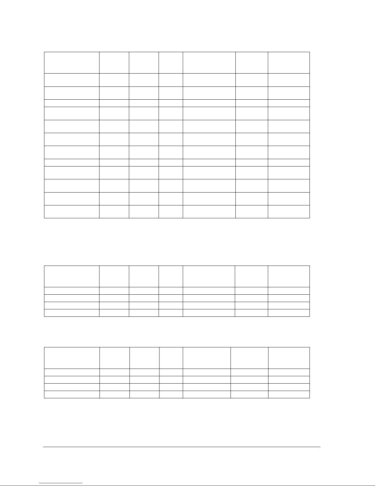
Table 1 : VoltMax 600 VAC / 60 Hz / 3 Phases
1
Model
BTU/h
kW
Amps
Elements 600V
Stage
2
max. power
supply
(MCM)3
VoltMax 192
655 104
192
185
8 x 15 kW
4 x 18 kW
4 x 48 kW
3 x 350
VoltMax 204
696 048
204
197
8 x 18 kW
4 x 15 kW
4 x 51 kW
3 x 350
VoltMax 216
736 996
216
208
12 x 18 kW
4 x 54 kW
3 x 350
VoltMax 225
767 700
225
217
15 x 15 kW
5 x 45 kW
3 x 350
VoltMax 240
818 880
240
231
10 x 15 kW
5 x 18 kW
5 x 48 kW
3 x 350
VoltMax 255
870 060
255
246
10 x 18 kW
5 x 15 kW
5 x 51 kW
3 x 350
VoltMax 270
921 240
270
260
15 x 18 kW
5 x 54 kW
3 x 500
VoltMax 288
982 656
288
277
12 x 15 kW
6 x 18 kW
6 x 48 kW
3 x 500
VoltMax 306
1 044 072
306
295
12 x 18 kW
6 x 15 kW
6 x 51 kW
3 x 500
VoltMax 315
1 074 780
315
303
21 x 15 kW
7 x 45 kW
3 x 500
VoltMax 324
1 105 488
324
312
18 x 18 kW
6 x 54 kW
3 x 500
VoltMax 336
1 146 432
336
324
14 x 15 kW
7 x 18 kW
7 x 48 kW
3 x 600
VoltMax 357
1 218 084
357
344
14 x 18 kW
7 x 15 kW
7 x 51 kW
3 x 600
VoltMax 378
1 289 736
378
364
21 x 18 kW
7 x 54 kW
6 x 300
VoltMax 384
1 310 208
384
370
16 x 15 kW
8 x 18 kW
8 x 48 kW
6 x 300
VoltMax 408
1 392 096
408
393
16 x 18 kW
8 x 15 kW
8 x 51 kW
6 x 300
1
Electrical supply 600 V 3 phase (L1-L2-L3) with 3 conductors Cu or AL ,90 °C with a ground.
2
The 45 kW stage is composed of three 15 kW elements.
The 48 kW stage is composed of two 15 kW elements and one 18 kW element.
The 51 kW stage is composed of one 15 kW element and two 18 kW elements.
The 54 kW stage is composed of three 18 kW elements.
3
-Maximum capacity of the boilers connection terminals
VOLTMAX ELECTRIC BOILER Installation and Operation Manual (Revised March 2019), Page 5.
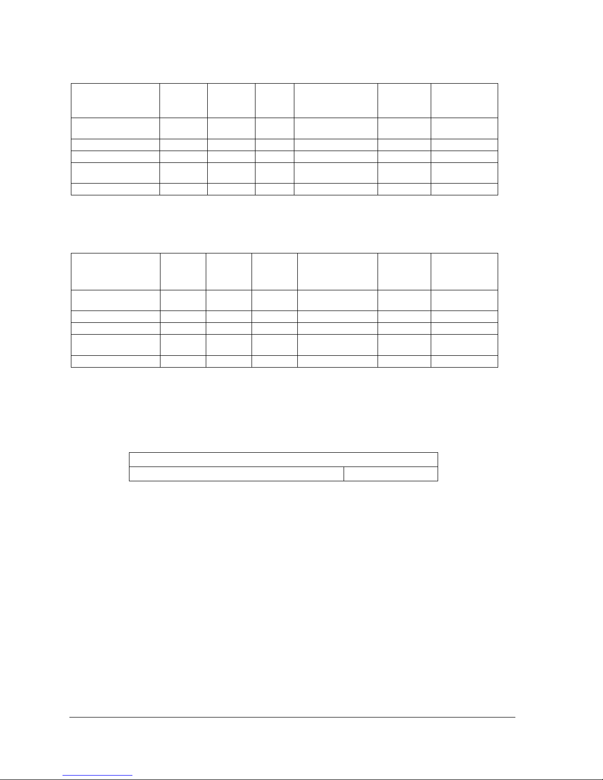
Table 2 : VoltMax 480 VAC / 60 Hz / 3 Phases
1
Model
BTU/h
kW
Amps
Elements 480V
Stage
2
max. power
supply
(MCM)3
VoltMax 192
655 104
192
231
8 x 15 kW
4 x 18 kW
4 x 48 kW
3 x 350
VoltMax 204
696 048
204
246
8 x 18 kW
4 x 15 kW
4 x 51 kW
3 x 500
VoltMax 225
767 700
225
271
15 x 15 kW
5 x 45 kW
3 x 500
VoltMax 240
818 880
240
289
10 x 15 kW
5 x 18 kW
5 x 48 kW
3 x 500
VoltMax 255
870 060
255
307
10 x 18 kW
5 x 15 kW
5 x 51 kW
3 x 500
VoltMax 288
982 656
288
347
12 x 15 kW
6 x 18 kW
6 x 48 kW
3 x600
VoltMax 306
1 044 072
306
368
12 x 18 kW
6 x 15 kW
6 x 51 kW
3 x600
VoltMax 315
1 074 780
315
379
21 x 15 kW
7 x 45 kW
6 x 300
VoltMax 336
1 146 432
336
405
14 x 15 kW
7 x 18 kW
7 x 48 kW
6 x 300
VoltMax 357
1 218 084
357
430
14 x 18 kW
7 x 15 kW
7 x 51 kW
6 x 300
VoltMax 384
1 310 208
384
462
16 x 15 kW
8 x 18 kW
8 x 48 kW
6 x 300
VoltMax 408
1 392 096
408
491
16 x 18 kW
8 x 15 kW
8 x 51 kW
6 x 500
1
Electrical supply 480 V 3 phase (L1-L2-L3) with 3 conductors Cu or AL ,90 °C with a ground.
2
The 45 kW stage is composed of three 15 kW elements.
The 48 kW stage is composed of two 15 kW elements and one 18 kW element.
The 51 kW stage is composed of one 15 kW element and two 18 kW elements.
3
-Maximum capacity of the boilers connection terminals
Table 3 : VoltMax 240 VAC / 60 Hz / 3 Phases
1
Model
BTU/h
kW
Amps
Elements 240V
Stage
max. power
supply
(MCM)2
VoltMax 105
358 260
105
253
7 x 15 kW
7 x 15 kW
3 x 500
VoltMax 120
409 440
120
289
8 x 15 kW
8 x 15 kW
3 x 500
VoltMax 126
429 912
126
303
7 X 18 kW
7 X 18 kW
3 x 500
VoltMax 144
491 328
144
347
8 x 18 kW
8 x 18 kW
3 x 500
1
Electrical supply 240 V 3 phase (L1-L2-L3) with 3 conductors Cu or AL ,90 °C with a ground.
2
-Maximum capacity of the boilers connection terminals
Table 4 : VoltMax 208 VAC / 60 Hz / 3 Phases
1
Model
BTU/h
kW
Amps
Elements 240V
2
Stage
max. power
supply
(MCM)3
VoltMax 79
268 695
78,75
219
7 x 15 kW
7 x 11,25 kW
3 x 350
VoltMax 90
307 080
90
250
8 x 15 kW
8 x 11,25 kW
3 x 500
VoltMax 95
322 434
94,5
263
7 X 18 kW
7 X 13,5 kW
3 x 500
VoltMax 108
368 496
108
300
8 x 18 kW
8 x 13,5 kW
3 x 500
1
Electrical supply 208 V 3 phase (L1-L2-L3) with 3 conductors Cu or AL ,90 °C with a ground.
2
240V electrical element operated at 208V
3
-Maximum capacity of the boilers connection terminals
VOLTMAX ELECTRIC BOILER Installation and Operation Manual (Revised March 2019), Page 6.
Table 5 : VoltMax 240 VAC / 60 Hz / 1 Phase
1
Model
BTU/h
kW
Amps
Elements 240V
Stage
2
max. power
supply
(MCM)3
VoltMax 77
262 724
77
321
7 x 5 kW
7 x 6 kW
7 x 11 kW
2 x 500
VoltMax 80
272 960
80
333
16 x 5 kW
8 x 10 kW
2 x 600
VoltMax 84
386 608
84
350
14 x 6 kW
7 X 12 kW
2 x 600
VoltMax 88
300 256
88
366
8 x 5 kW
8 x 6 kW
8 x 11 kW
4 x300
VoltMax 96
327 552
96
400
16 x 6 kW
8 x 12 kW
4 x 300
1
Electrical supply 240 V 2 phase (L1-L2) with 2 conductors Cu or AL ,90 °C with a ground.
2
The 10 kW stage is composed of two 5kW elements
The 11 kW stage is composed of one 5 kW element et one 6 kW element
The 12 kW stage is composed of two 6 kW elements.
3
-Maximum capacity of the boilers connection terminals
Table 6 : VoltMax 208 VAC / 60 Hz / 1 Phase
1
Model
BTU/h
kW
Amps
Elments 240V
2
Stage
3
max. power
supply
(MCM)4
VoltMax 58
197 043
57.75
278
7 x 5 kW
7 x 6 kW
7 x 8.25
kW
2 x 500
VoltMax 60
204 720
60
288
16 x 5 kW
8 x 7.5 kW
2 x 500
VoltMax 63
214 956
63
303
14 x 6 kW
7 X 9 kW
2 x 500
VoltMax 66
225 192
66
317
8 x 5 kW
8 x 6 kW
8 x 8.25
kW
2 x 500
VoltMax 72
245 664
72
346
16 x 6 kW
8 x 9 kW
2 x 600
1
Electrical supply 240 V 2 phase (L1-L2) with 2 conductors Cu or AL ,90 °C with a ground.
2
240 electrical element operated at 208V
3
The 7.5 kW stage is composed of two 5kW elements
The 8.25 kW stage is composed of one 5 kW element et one 6 kW element
The 9 kW stage is composed of two 6 kW elements.
4
- Maximum capacity of the boilers connection terminals
Table 7 : Maximum operating pressure
All models
1
Standard maximum operating pressure
160 PSI
1
Safety valeve pressure of 60 psi, 125 psi or 150 psi (Standard).
VOLTMAX ELECTRIC BOILER Installation and Operation Manual (Revised March 2019), Page 7.
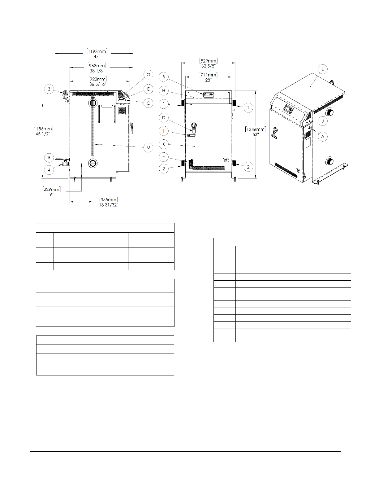
BOILER DIMENSIONS AND CHARACTERISTICS
* Optional disconnect switch available on "THREE-PHASE" models.
BOILER CONNECTIONS
1
Boiler outlet
3 " NPT M
2
Boiler inlet
3 " NPT M
3
Pressure relief valve
3/4" NPT F
4
Drain valve
1 1/4 " NPT F
5*
Access to the return sensor
1/2 " NPT F
MIN. CLEARANCES FOR INSTALLATION &
MAINTENANCE
Left and Right sides
6"/ 152mm
Rear
6"/ 152mm
Front
24" / 610mm
Bottom
0" / 0mm
Top
32" / 813mm
GENERAL INFORMATIONS
Weight
1200 lbs / 545 kg
Water Volume
62 Us gal. / 235 liters
Max. operating
pressure
STANDARD: 160psi
COMPONENTS IDENTIFICATION
A
Electrical main supply
B
Boiler controller
C
"On/Off" switch
D*
Disconnect switch & rotary handle
E
Fuses for controls
F
Solid state SCR relay
G
Low water cut-off, test button and indicator
lights
H
Electrical control access door
I
Door handle for electric access with lock
J
Electrical control wires access holes
K
Access door power circuit
L
Access cover to Heating elements
M
Heating elements
VOLTMAX ELECTRIC BOILER Installation and Operation Manual (Revised March 2019), Page 8.
General Safety Precautions
Be sure to read and understand the entire Installation & operation manual before attempting to install or to operate this water
heater. Pay attention to the following General Safety Precautions. Failure to follow these warnings could cause property damage,
bodily injury or death. Should you have any problems understanding the instructions in this manual, STOP, and get help from a
qualified installer or technician
INTRODUCTION
These important safeguards and instruction appearing in this manual are not meant to cover all
possible conditions and situations that may occur. Common sense,
caution and care are factors that cannot be built into every product. These factors must be
supplied by the person(s) caring for and operating the unit.
LOCAL INSTALLATION
REGULATIONS
This electric boiler must be installed in
accordance with these instructions and in
conformity with local codes, or in the absence of
local codes, with the National Plumbing Code and
the National Electric Code, current edition. In any
case where instructions in this manual differ from
local or national codes, the local or national codes
take precedence.
CORROSIVE ENVIRONMENT
The electric boiler must not be installed near an
air duct supplying corrosive atmosphere or with
high humidity content. When a boiler defect is
caused by such conditions, the warranty will not
apply.
INSPECTION UPON RECEPTION
Inspect the electric boiler for possible shipping
damage. The manufacturer’s responsibility
ceases upon delivery of goods to the carrier in
good condition. The Consignee must file any
claims for damage, shortage in shipments, or
non-delivery immediately against the carrier.
TO BE CHECKED
Please refer to the rating plate on the unit to
ensure that you have the correct model and
voltage in hand.
List of components shipped with the unit:
• Pressure relief valve
• Drain valve
• Outdoor temperature sensor ¸
(Located inside the control panel of the
unit)
The electric boiler should not be installed where it may damage the adjacent structures or lower
floors in the event of leakage of the tank or connections. If this cannot be avoided, install a nonflammable tray or bowl under the boiler to collect and drain water from leaks.
NOTE: Any tray or cuvette MUST conform to local codes.
!
AVERTISSEMENT
!
WARNING
!
VOLTMAX ELECTRIC BOILER Installation and Operation Manual (Revised March 2019), Page 9.
INSTALLATION
The manufacturer’s warranty does not cover any damage or defect caused by installation, or
attachment, or use of any special attachment other than those authorized by the manufacturer into,
onto, or in conjunction with the water heater. The use of such unauthorized devices may shorten
the life of the boiler and may endanger life and property. The manufacturer disclaims any
responsibility for such loss or injury resulting from the use of such unauthorized devices
SAFETY MEASURES
Any commercial installation will be equipped with
a safety valve that limits the maximum working
pressure to the maximum design pressure of the
tank. The maximum operating pressure of the
VoltMax Boiler with a power of 90kW and less is
30 psi or 70 psi, depending on the options chosen.
The maximum operating pressure of the VoltMax
boiler with a power of more than 90kW is 60 psi or
125 psi, depending on the options selected. See
boiler data sheet for maximum operating pressure.
The boiler is equipped with an automatic high limit
temperature control set at 210°F (99°C) and a
second manual high limit temperature settable.
This electric boiler is designed to operate at a
maximum operating temperature of 200 ° F (93 °
C). The boiler is designed for use in a hot water
heating system only.
The heat transfer fluid must be water or an
antifreeze water / propylene glycol solution or
an antifreeze water / ethylene glycol solution
specially designed for heating systems. The
maximum concentration of solution must be a
maximum of 50%.
LOCATION
The electric boiler should be installed in a clean,
dry location. Long hot water lines should be
insulated to conserve water and energy. The
electric boiler and water lines should be protected
from exposure to freezing temperature.
The boiler can be mounted vertically or
horizontally directly on a solid surface.
The electric boiler must be located or protected
to avoid risk of physical damage, such as from
moving vehicles, flooding, etc.
The location must have sufficient ventilation to
maintain an ambient temperature not exceeding
80°F (27°C).
To prevent condensation on the boiler walls,
boiler temperature should not be maintained
below the condensation temperature (dewpoint temperature) of the ambient. The
operating temperature of the boiler must not
be lower than the condensation temperature
(dew temperature) relative to the ambient
humidity content.
CLEARANCES
For adequate inspection and servicing the
following minimum clearance is necessary:
Table 8 : Boiler Clearances
Sides**
3 inches / 76 mm
Bottom
0 inches / 0 mm
Top*
32 inches / 813 mm
Front
24 inches / 610 mm
Back
3 inches / 76 mm
* A minimum clearance of 32 inches. For units
equipped with 18 kW elements (25 in. For 15 kW
elements) is required for possible replacement of
heating elements.
** The left side of the control panel, where the
boiler ON / OFF switch is located, must remain
visible after installation. Otherwise, a label
indicating its location must be affixed to the
control panel indicating its position.
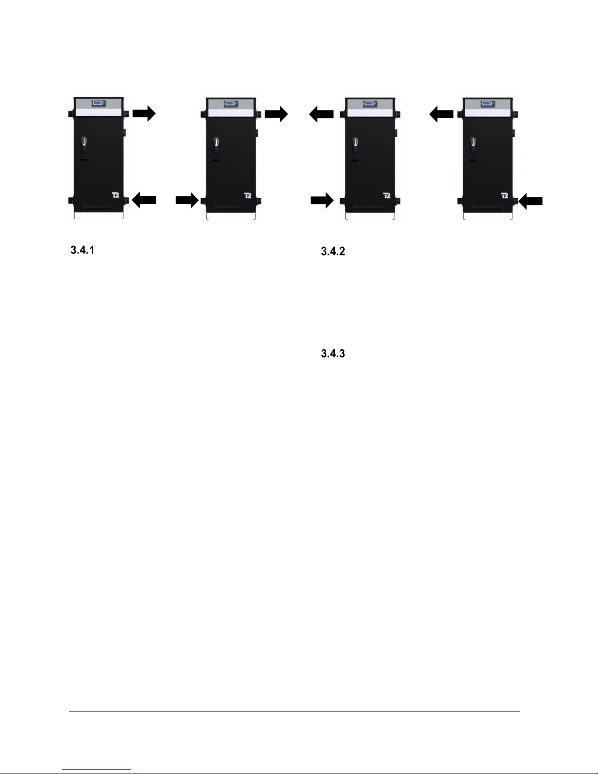
PIPING INSTALLATION
The location of the inlet and outlet piping shall
conform to the various configurations shown in
Figure 1. You will find typical connection diagrams
to the Figure 3, Figure 4 and Figure 5.
The VoltMax boiler is designed to be operated
on a closed-circuit piping system. Therefore, it
should not be used to heat open air tanks
MISE EN GARDE
!
VOLTMAX ELECTRIC BOILER Installation and Operation Manual (Revised March 2019), Page 10.
Figure 1 : Possible pipe flow configurations
BOILER PIPING CONNECTION
The boiler is equipped with two fittings on each
side of the unit. One of the bottom connections
must be used for the heating return (inlet) and one
of the top connections must be used for supplying
the heating system (outlet).
The outlet and inlet size are 1½ "NPTM threaded
steel pipes, for the VoltMax with a power of 90kW
and less and 2½ "NPTM threaded steel pipes for
the VoltMax with a power of More than 90kW.
Installation of plugs on the inlet and exhaust ducts
is required to facilitate the disconnection and
maintenance of the boiler.
When connecting different types of pipes
(galvanized steel and copper), use dielectric joints
(insulation) to protect the boiler and piping.
Use only new and clean pipes as piping
connection to the boiler. Local codes or
regulations may dictate the exact type of material
to be used.
Insulate all piping containing hot water, especially
in an unheated environment.
Install faucets for easy maintenance.
Install a thermometer on the inlet and outlet
duct(s).
Close the unused openings on the boiler. Do not
block the safety valve, this may cause loss,
damage or injury.
AUXILIARY BOILER PIPING
CONNECTION
When an auxiliary boiler used as back up is
twinned to the VoltMax boiler to act as a back-up
controlled by the VOTLMAX, the auxiliary
boiler shall be installed downstream of the electric
boiler as shown on Figure 5 and 7.
SAFETY VALVE
The installation of a safety valve is an integral part
of the boiler’s installation. The trigger point of the
valve must not exceed the design pressure of the
boiler as indicated on its registration and
identification plate. The valve must comply with the
ASME Boiler and Pressure Vessel Code and limit
the boiler maximum operating pressure. The
safety valve is a security component, not a control
component.
The capacity of the safety valve expressed in BTU
/ hour must equal or exceed the rating on the
nameplate of the boiler (s).
A safety valve adjusted to the maximum design
pressure of the boiler has been installed at the
factory. The latter can be replaced by a valve with
a lower trigger pressure, but its BTU / hour
capacity must not be lower than the maximum
boiler power.
Connect the exhaust of the safety valve to a drain
line. The lower end of this conduit shall be at least
6" (15 cm) from the floor drain away from any
electrical component. The drain line must be
directed downwards from the exhaust of the safety
valve to ensure complete drainage by gravity. The
diameter of the drainpipe must not be less than
that of the exhaust of the valve. The end of the
conduit must not be threaded or hidden and must
VOLTMAX ELECTRIC BOILER Installation and Operation Manual (Revised March 2019), Page 11.
be protected from freezing. No valves, valves or
valves shall be installed on the pipe. The
installation of the safety valves is governed by the
local code.
SYSTEM PRESSURE CONTROL
AND EXPANSION TANK
Pressure control devices within the system ensure
that each component operates within minimum
and maximum allowable pressures and maintain
minimum pressure for all normal operating
temperatures. They also allow air bleeding,
prevent cavitation at the pump inlet and prevent
water from boiling within the system; all this is
accomplished with minimal addition of new water.
The increase in boiler water volume resulting from
higher temperature is stored in the expansion tank
during periods of high operating temperature and
is returned to the system when the temperature
decreases.
The expansion tank must be able to store the
required volume of boiler water during maximum
design operating temperature without exceeding
the maximum allowable operating pressure, and to
maintain the required minimum pressure when the
system is cold. Contact your installing contractor,
plumbing supply house, or local plumbing
inspector for assistance. The point where the
expansion tank is connected should be carefully
selected to avoid the possibility that normal
operation of automatic check or manual valves will
isolate the tank from a hot boiler or any part of the
system.
The expansion tank should preferably be located
on the suction or intake side of the pump.
WATER PRESSURE MAKEUP
REGULATOR
Make-up systems must be employed as required
by codes. An automatic fill valve (automatic
pressure regulator) must be used with a backflow
preventer as required, to maintain minimum
system pressure by supplying water to make up for
leakage.
A minimum pressure of 5psi (34kPa) must be
maintained at all times.
A backflow prevention device that complies with
local standards must be installed upstream of the
pressure regulator.
AIR BLEEDER
The air contained in the heated water must be
removed from the system to allow the proper
functioning of the heating system and the boiler.
Installation of manual or automatic air vents is
required to eliminate all air from the boiler and the
heating distribution system.
The main air eliminator must be installed near the
outlet of the boiler on the highest point of the main
supply piping. It is imperative to ensure that all air
possibly located in the boiler be eliminated at all
time.
Regularly purge air from the pipes and beware that
the heated water does not cause injury or damage.
If the boiler is located at a location higher than the
heat distribution system such as a heated floor, an
automatic air eliminator should be installed close
to the boiler outlet.
CIRCULATING PUMP
The pump capacity required is determined in
relation to the capacity of the boiler installed and
the type of heating distribution system on which it
will be connected.
They are generally designed for an operation at a
differential of temperature (Delta T0) of 10 to 20F
between the supplies and return temperature to
the boiler.
Use the following equation to determine the
required water flow.
Pump flow rate = Boiler power ÷ Delta T ÷ 500
• Pump flow rate is expressed in US gallons per
minute or GPM.
• The Boiler output (in net BTU per hour) is the
maximum amount of heat to be transferred
through the heating loop to meet the heating
load.
• Delta T: The boiler water temperature drop
For example, an electric boiler rated at 180KW has
an output capacity of 614 160 BTU per hour. The
system is designed for a temperature drop of 20°F.
Required pump flow rate = 614,160 20 500 =
61,4 GPM
VOLTMAX ELECTRIC BOILER Installation and Operation Manual (Revised March 2019), Page 12.
For example, an 180kW electric boiler has a power
of 614,160 BTU/h. The system is designed for a
drop-in temperature (Delta T) of 20°F.
Flow required = 614,160 20 500 = 61.4 GPM
N.B. To achieve proper operation, a minimum flow
must be present when a heating request is applied
and the heating elements are in operation. In the
table below, the column representing a differential
of 50°F indicates the minimum recommended flow
for each boiler output. Installation of a flow switch
is not mandatory. If installed, its contact must be
connected between 24V+ and W1 (operation
authorization)
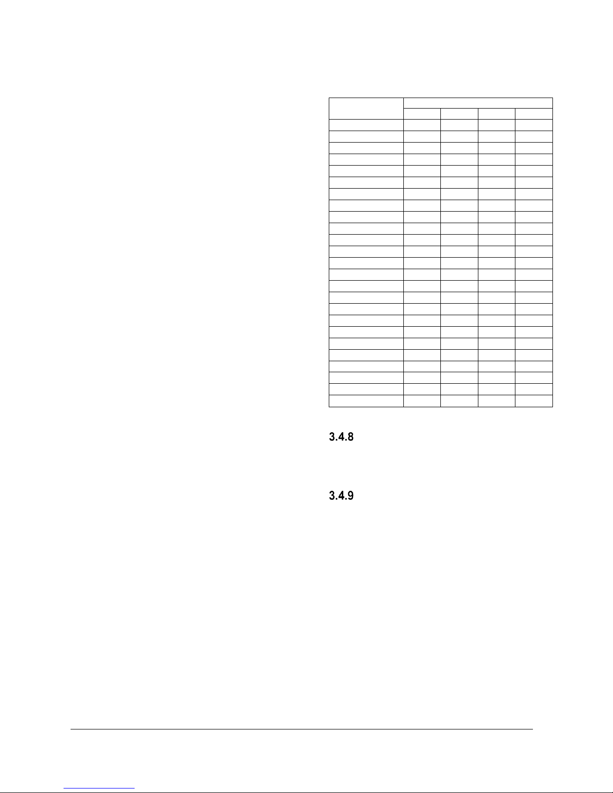
The following table lists the required pump flow
rate in relation to the boiler capacity and Delta T.
Table 9 : Temperature rise vs flow rate
(GPM)
MODEL
DELTA T0
10oF
20oF
30oF
40oF
VoltMax 77
52,5
26,3
17,5
13,1
VoltMax 80
54,6
27,3
18,2
13,6
VoltMax 84
57,3
28,7
19,1
14,3
VoltMax 88
60,1
30,0
20,0
15,0
VoltMax 96
65,5
32,8
21,8
16,4
VoltMax 105
71,7
35,8
23,9
17,9
VoltMax 120
81,9
40,9
27,3
20,5
VoltMax 126
86,0
43,0
28,7
21,5
VoltMax 144
98,3
49,1
32,8
24,6
VoltMax 192
131,0
65,5
43,7
32,8
VoltMax 204
139,2
69,6
46,4
34,8
VoltMax 216
147,4
73,7
49,1
36,8
VoltMax 225
153,5
76,8
51,2
38,4
VoltMax 240
163,8
81,9
54,6
40,9
VoltMax 255
174,0
87,0
58,0
43,5
VoltMax 270
184,2
92,1
61,4
46,1
VoltMax 288
196,5
98,3
65,5
49,1
VoltMax 306
208,8
104,4
69,6
52,2
VoltMax 315
215,0
107,5
71,7
53,7
VoltMax 324
221,1
110,5
73,7
55,3
VoltMax 336
229,3
114,6
76,4
57,3
VoltMax 357
243,6
121,8
81,2
60,9
VoltMax 378
257,9
129,0
86,0
64,5
VoltMax 384
262,0
131,0
87,3
65,5
VoltMax 408
278,4
139,2
92,8
69,6
*Minimum flow
DRAIN FAUCET
A drain valve is installed behind the unit. It allows
the boiler to be emptied, to make possible the
replacement of defective components.
SIEVE
A sieve or other accessorie that collects sediments
should be installed on systems where high particle
concentration may existe. Sediments may
eventually get to the elements and cause damage
to the elements. The warranty does not cover
damages in this case.
VOLTMAX ELECTRIC BOILER Installation and Operation Manual (Revised March 2019), Page 13.
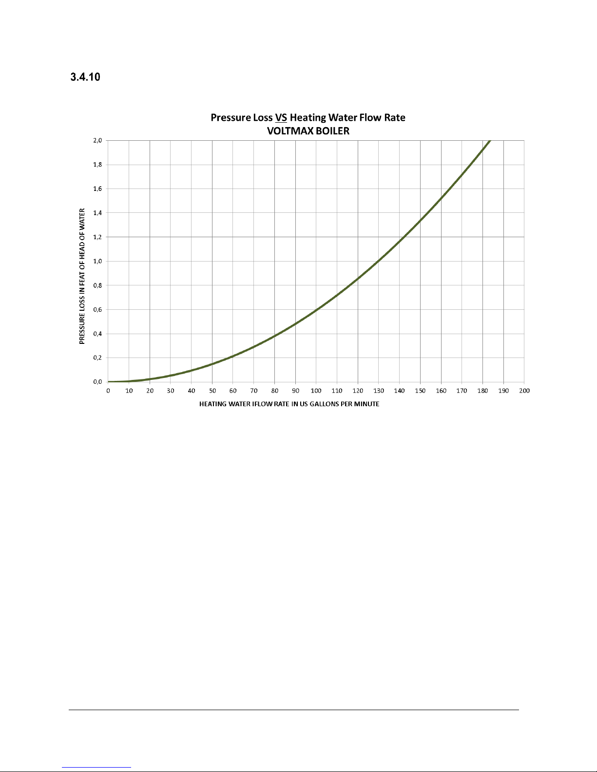
PRESSURE LOSS
The graph of pressure loss due to flow of water inside the VoltMax boiler is shown in the following figure.
Figure 2 : Pressure loss (FTH) as a function of the flow rate of heated water (GPM)
VOLTMAX ELECTRIC BOILER Installation and Operation Manual (Revised March 2019), Page 14.
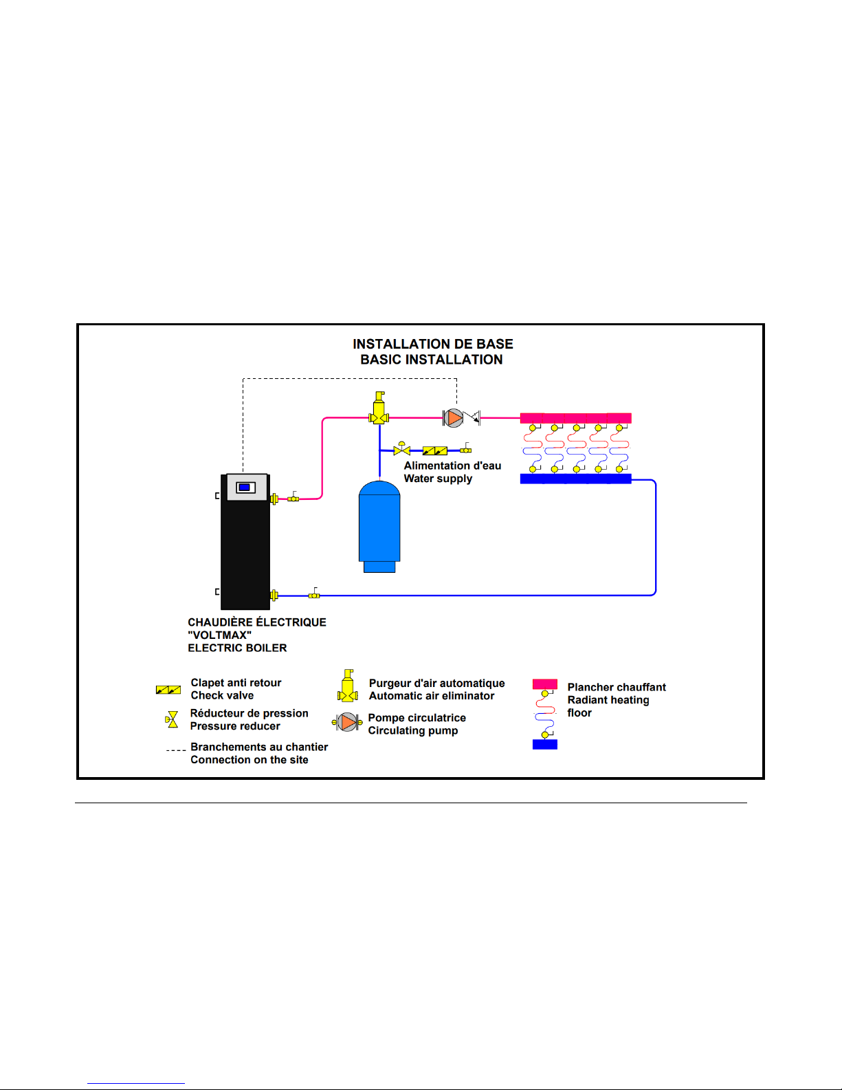
Figure 3 : Basic installation
VOLTMAX ELECTRIC BOILER Installation and Operation Manual (Revised March 2019), Page 15.
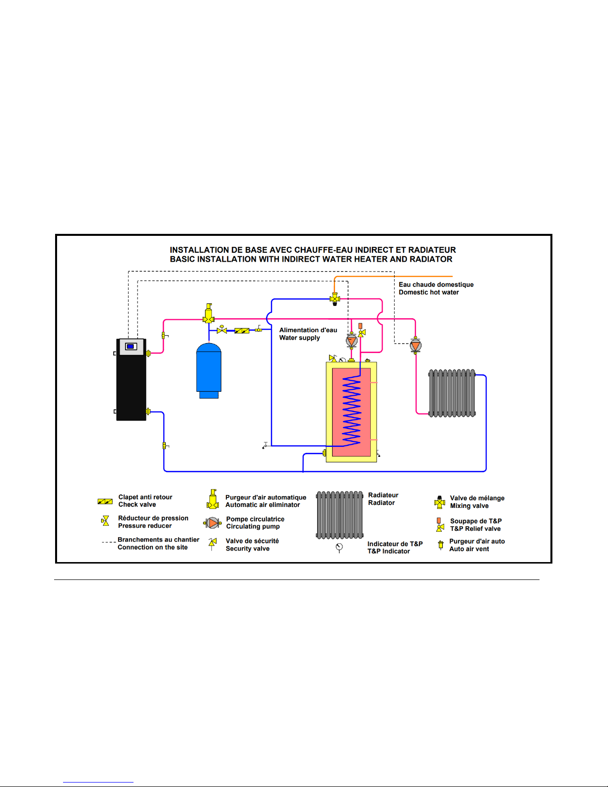
Figure 4 : Basic installation with indirect water heater and radiator
VOLTMAX ELECTRIC BOILER Installation and Operation Manual (Revised March 2019), Page 16.
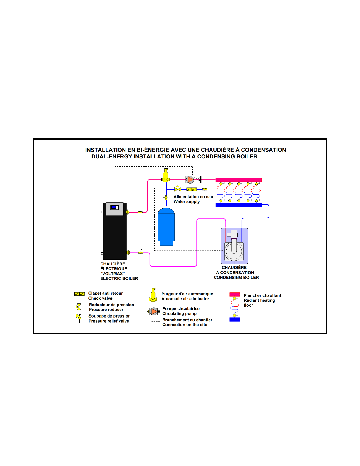
Figure 5 : Dual-Energy installation with a condensing boiler
VOLTMAX ELECTRIC BOILER Installation and Operation Manual (Revised March 2019), Page 17.
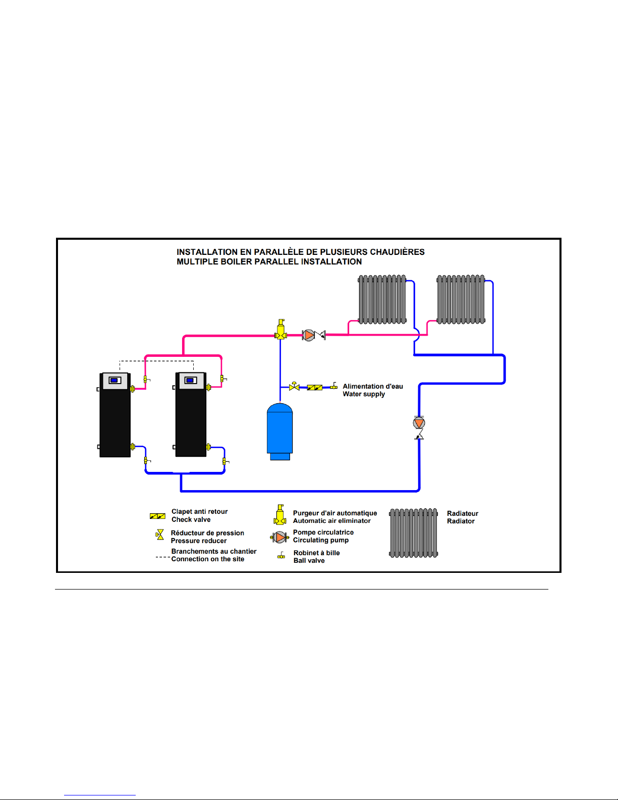
Figure 6 : Multiple boiler parallel installation
VOLTMAX ELECTRIC BOILER Installation and Operation Manual (Revised March 2019), Page 18.
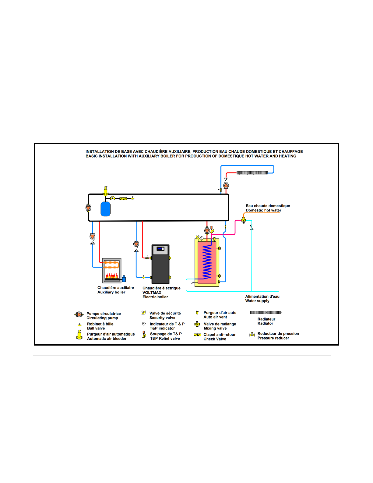
Figure 7 : Basic installation with auxiliary boiler for production of domestic hot water and heating
 Loading...