

THERMO 2000 VOLTMAX 36, VOLTMAX 27, VOLTMAX 30, VOLTMAX 41, VOLTMAX 50 Installation And Operation Manual
...
1
VOLTMAX Electric Boiler
Your VOLTMAX Electric Boiler was carefully assembled and checked at the factory to ensure its proper
functioning for many years. The following information and safety measures are provided to enable
proper installation, operation, and maintenance of this product.
It is imperative that all persons who are expected to install, operate or adjust this boiler should read
these instructions carefully.
Any questions regarding the operation, maintenance, service or warranty of this electric boiler should be
directed to the installer or to a skilled technician.
When all installation steps have been completed, keep this installation manual in a safe place (near the
boiler) for future reference.
THERMO 2000 INC.
Printed in Canada Revised: August 2017
INSTALLATION AND OPERATION MANUAL
mo

TABLE OF CONTENTS
SECTION 1 : TECHNICAL SPECIFICATIONS ............................................................... 4
SECTION 2 : INTRODUCTION ....................................................................................... 9
2.1 LOCAL INSTALLATION REGULATIONS ............................................................................. 9
2.2 CORROSIVE ENVIRONMENT.............................................................................................. 9
2.3 INSPECTION UPON RECEPTION ....................................................................................... 9
2.4 TO BE CHECKED ................................................................................................................. 9
SECTION 3 : INSTALLATION ...................................................................................... 10
3.1 SAFETY MEASURES .......................................................................................................... 10
3.2 LOCATION........................................................................................................................... 10
3.3 CLEARANCES .................................................................................................................... 10
3.4 PIPING INSTALLATION ...................................................................................................... 10
3.4.1 Boiler piping connection ............................................................................................... 11
3.4.2 Auxiliary boiler piping connection ................................................................................. 11
3.4.3 Safety valve .................................................................................................................. 11
3.4.4 System pressure control and expansion tank .............................................................. 12
3.4.5 Water pressure makeup regulator ................................................................................ 12
3.4.6 Air bleeder .................................................................................................................... 12
3.4.7 Circulating pump .......................................................................................................... 12
3.4.8 Drain faucet .................................................................................................................. 13
3.4.9 Pressure loss ................................................................................................................ 14
3.5 ELECTRICAL CONNECTIONS ........................................................................................... 20
3.5.1 Main electrical supply ................................................................................................... 20
3.5.2 Pump supply ................................................................................................................. 20
3.5.3 Connection of external signals to the controller ........................................................... 20
SECTION 4 : CONTROLLER OPERATION ................................................................. 23
4.1 USER INTERFACE ............................................................................................................. 23
4.1.1 Symbol description ....................................................................................................... 23
4.1.2 Control panel ................................................................................................................ 24
4.1.3 Navigation and adjustements ....................................................................................... 24
4.1.4 Main menu navigation .................................................................................................. 25
4.1.5 Navigation in boiler setting ........................................................................................... 26
4.2 MAIN MENU ........................................................................................................................ 29
4.2.1 Boiler status .................................................................................................................. 29
4.2.2 Boiler configuration ....................................................................................................... 29
4.2.3 User setting .................................................................................................................. 29
4.2.4 Clock setting ................................................................................................................. 30
4.2.5 Consumption ................................................................................................................ 30
4.3 BOILER SETTINGS ............................................................................................................. 30
4.3.1 Heating mode W1 ......................................................................................................... 31
4.3.2 Heating mode W2/DHW ............................................................................................... 31
4.3.3 Pump setting................................................................................................................. 32
4.3.4 Capacity limiting ........................................................................................................... 32
4.3.5 Auxiliary boiler .............................................................................................................. 33
4.3.6 Limit setting .................................................................................................................. 34
4.3.7 Alarm ............................................................................................................................ 34
4.3.8 Communication............................................................................................................. 35
4.3.9 Occupation ................................................................................................................... 36
4.3.10 BOOST Mode ............................................................................................................. 36
4.3.11 Warm weather shutdown ............................................................................................ 37
4.3.12 Change password ...................................................................................................... 37
4.4 INTERNET ........................................................................................................................... 37
VOLTMAX ELECTRIC BOILER Installation and Operation Manual (Revised August 2017), Page 2.

4.4.1 Website ......................................................................................................................... 37
4.4.2 Email ............................................................................................................................. 37
4.5 BOILER STATUS DISPLAY SETTINGS ............................................................................. 39
4.6 HEATING MODE W1 SETTINGS ....................................................................................... 41
4.6.1 FIXED MODE ............................................................................................................... 41
4.6.2 OUTDOOR RESET MODE .......................................................................................... 42
4.6.3 Mode : DDC 0-10VDC .................................................................................................. 43
4.7 W2 MODE SET-POINT TEMPERATURE SETTINGS ........................................................ 44
4.7.1 W2 MODE .................................................................................................................... 44
4.7.2 DHW MODE ................................................................................................................. 44
4.8 PUMP CONFIGURATION MENU SETTINGS .................................................................... 44
4.8.1 PUMP 1 ........................................................................................................................ 44
4.8.2 PUMP 2 ........................................................................................................................ 44
SPECIFIC PARAMETERS FOR THE CAPACITY LIMITING MENU .................................... 45
4.8.3 MANUAL MODE ........................................................................................................... 45
4.8.4 MODE: 0-10 VDC ......................................................................................................... 45
4.9 POWER LIMITATION MENU SETTINGS ........................................................................... 46
4.9.1 MANUAL MODE ........................................................................................................... 46
4.9.2 0-10 VDC MODE .......................................................................................................... 46
4.9.3 T. ext MODE ................................................................................................................. 47
4.9.4 Schedule MODE ........................................................................................................... 48
4.10 AUXILIARY BOILER SETTINGS ....................................................................................... 49
4.10.1 BACKUP MODE ......................................................................................................... 49
4.10.2 EXTERNAL CONTACT MODE .................................................................................. 50
4.10.3 ManuAl MODE ........................................................................................................... 50
4.10.4 Bi-Energy MODE ........................................................................................................ 50
4.11 LIMIT CONFIGURATION MENU SETTINGS .................................................................... 51
4.12 CONFIG. ALARM MENU SETTINGS ................................................................................ 52
4.13 OCCUPATION MENU SETTINGS .................................................................................... 52
4.14 BOOST MENU SETTINGS................................................................................................ 53
4.15 WARM WEATHER SHUTDOWN MENU SETTINGS ....................................................... 53
SECTION 5 : BOILER START UP ................................................................................ 54
5.1 FILLING THE BOILER ......................................................................................................... 54
5.2 ADJUSTEMENT OF THE CONTROLLER OPERATING PARAMETERS .......................... 54
5.3 STARTUP PROCEDURE .................................................................................................... 54
SECTION 6 : TROUBLESHOOTING ............................................................................ 56
6.1 WARNING LIGHTS ............................................................................................................. 56
6.2 OPERATING PROBLEM IDENTIFICATION ....................................................................... 56
6.2.1 External HL / LWCO ............................................................................................... 56
6.2.2 Sensor ( SE ) .......................................................................................................... 56
6.2.3 Low limit ( LL ) ........................................................................................................ 56
6.2.4 Flow ( F ) ................................................................................................................ 56
6.2.5 Current ( A ) ............................................................................................................ 56
6.2.6 HL temperature ( HL ) ............................................................................................ 57
6.2.7 Low pressure ( P ) .................................................................................................. 57
6.2.8 High pressure ( P ) ................................................................................................. 57
6.2.9 Lock out .................................................................................................................. 57
SECTION 7 : MAINTENANCE ...................................................................................... 58
7.1 BOILER WATER PIPING .................................................................................................... 58
7.2 PRESSURE RELIEF VALVE ............................................................................................... 58
7.3 AIR PURGE ......................................................................................................................... 58
7.4 ELECTRICAL INSPECTION................................................................................................ 58
VOLTMAX ELECTRIC BOILER Installation and Operation Manual (Revised August 2017), Page 3.
Capacity
STG
Series
SCR Series
Model
kW
BTU/h
Amps
Electrical
element(s) 240 V
Stage
Relay
Stage
Relay
SCR
Stage
VOLTMAX 23
22,5
76 770
108,4
6 x 5 kW
3 x 7,5 kW
2 x 7,5 kW
1 x 7,5 kW
VOLTMAX 27
27
92 124
130,1
6 x 6 kW
3 x 9 kW
2 x 9 kW
1 x 9 kW
VOLTMAX 30
30
102 360
144,5
8 x 5 kW
4 x 7,5 kW
3 x 7,5 kW
1 x 7,5 kW
VOLTMAX 36
36
122 832
173,4
8 x 6 kW
4 x 9 kW
3 x 9 kW
1 x 9 kW
VOLTMAX 41
41
139 892
198,7
5 x 5 kW + 5 x 6 kW
5 x 8,25 kW
4 x 8,25 kW
1 x 8,25 kW
VOLTMAX 45
45
153 540
216,8
10 x 6 kW
5 x 9 kW
4 x 9 kW
1 x 9 kW
VOLTMAX 50
49,5
168 894
238,4
6 x 5 kW + 6 x 6 kW
6 x 8,25 kW
5 x 8,25 kW
1 x 8,25 kW
VOLTMAX 54
54
184 248
260,1
12 x 6 kW
6 x 9 kW
5 x 9 kW
1 x 9 kW
Capacity
STG
Series
SCR Series
Model
kW
BTU/h
Amps
Electrical
element(s) 240 V
Stage
Relay
Stage
Relay
SCR
Stage
VOLTMAX 30
30
102 360
125
6 x 5 kW
3 x 10 kW
2 x 10 kW
1 x 10 kW
VOLTMAX 36
36
122 832
150
6 x 6 kW
3 x 12 kW
2 x 12 kW
1 x 12 kW
VOLTMAX 40
40
136 480
166,7
8 x 5 kW
4 x 10 kW
3 x 10 kW
1 x 10 kW
VOLTMAX 48
48
163 776
200
8 x 6 kW
4 x 12 kW
3 x 12 kW
1 x 12 kW
VOLTMAX 55
55
187 660
229,2
5 x 5 kW + 5 x 6 kW
5 x 11 kW
4 x 11 kW
1 x 11 kW
VOLTMAX 60
60
204 720
250
10 x 6 kW
5 x 12 kW
4 x 12 kW
1 x 12 kW
VOLTMAX 66
66
225 192
275
6 x 5 kW + 6 x 6 kW
6 x 11 kW
5 x 11 kW
1 x 11 kW
VOLTMAX 72
72
245 664
300
12 x 6 kW
6 x 12 kW
5 x 12 kW
1 x 12 kW
Puissance
STG Series
SCR Series
Model
kW
BTU/h
Amps
Electrical
element(s)
240 V
Stage Relay
Stage
Relay
SCR Stage
VOLTMAX 23
22,5
76 770
62,6
6 x 5 kW
2 x 11,25 kW
1 x 11,25 kW
1 x 11,25 kW
VOLTMAX 27
27
92 124
75,1
6 x 6 kW
2 x 13,5 kW
1 x 13,5 kW
1 x 13,5 kW
VOLTMAX 34
34
116 008
93,9
9 x 5 kW
3 x 11,25 kW
2 x 11,25 kW
1 x 11,25 kW
VOLTMAX 41
40,5
138 186
112,6
9 x 6 kW
3 x 13,5 kW
2 x 13,5 kW
1 x 13,5 kW
VOLTMAX 45
45
153 540
125,1
12 x 5 kW
4 x 11,25 kW
3 x 11,25 kW
1 x 11,25 kW
VOLTMAX 54
54
184 248
150,2
12 x 6 kW
4 x 13,5 kW
3 x 13,5 kW
1 x 13,5 kW
VOLTMAX 56
56
191 072
156,4
15 x 5 kW
5 x 11,25 kW
4 x 11,25 kW
1 x 11,25 kW
VOLTMAX 68
67,5
230 310
187,7
15 x 6 kW
5 x 13,5 kW
4 x 13,5 kW
1 x 13,5 kW
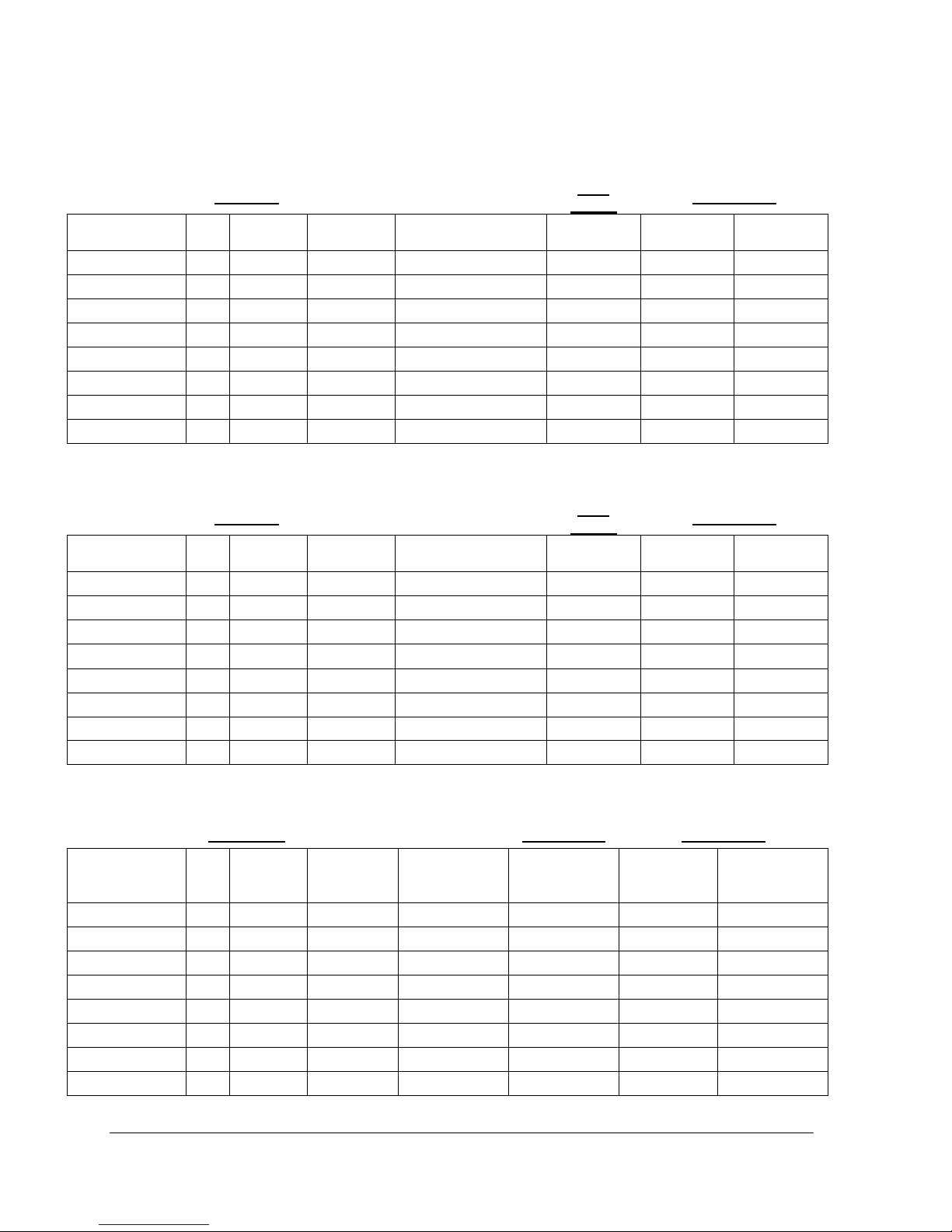
SECTION 1 : TECHNICAL SPECIFICATIONS
Table 1: VOLTMAX 208 VAC / 60 Hz / Single-Phase1
1
Electrical supply 208 V - 1 phase (L1-L2) with 2 conductors 90°C with a ground.
Table 2: VOLTMAX 240 VAC / 60 Hz / 1 Phase1
1
Electrical supply 240 V - 1 phase (L1-L2) with 2 conductors 90°C with a ground.
Table 3 : VOLTMAX 208 VAC / 60 Hz / 3 Phase1
1
Electrical supply 208 V - 1 phase (L1-L2) with 2 conductors 90°C with a ground.
VOLTMAX ELECTRIC BOILER Installation and Operation Manual (Revised August 2017), Page 4.
Capacity
STG
Series
SCR Series
Model
kW
BTU/h
Amps
Electrical
element(s) 240 V
Stage
Relay
Model
kW
VOLTMAX 30
30
102 360
72
6 x 5 kW
2 x 15 kW
1 x 15 kW
1 x 15 kW
VOLTMAX 36
36
122 832
86,6
6 x 6 kW
2 x 18 kW
1 x 18 kW
1 x 18 kW
VOLTMAX 45
45
153 540
108,3
9 x 5 kW
3 x 15 kW
2 x 15 kW
1 x 15 kW
VOLTMAX 54
54
184 248
129,9
9 x 6 kW
3 x 18 kW
2 x 18 kW
1 x 18 kW
VOLTMAX 60
60
204 720
144,3
12 x 5 kW
4 x 15 kW
3 x 15 kW
1 x 15 kW
VOLTMAX 72
72
245 664
173,2
12 x 6 kW
4 x 18 kW
3 x 18 kW
1 x 18 kW
VOLTMAX 75
75
255 900
180,4
15 x 5 kW
5 x 15 kW
4 x 15 kW
1 x 15 kW
Capacity
STG Series
SCR Series
Model
kW
BTU/h
Amps
Electrical
element(s)
240 V
Stage Relay
Model
kW
VOLTMAX 30
30
102 360
36,1
6 x 5 kW
2 x 15 kW
1 x 15 kW
1 x 15 kW
VOLTMAX 36
36
122 832
43,3
6 x 6 kW
2 x 18 kW
1 x 18 kW
1 x 18 kW
VOLTMAX 45
45
153 540
54,1
9 x 5 kW
3 x 15 kW
2 x 15 kW
1 x 15 kW
VOLTMAX 54
54
184 248
65
9 x 6 kW
3 x 18 kW
2 x 18 kW
1 x 18 kW
VOLTMAX 60
60
204 720
72,2
12 x 5 kW
4 x 15 kW
3 x 15 kW
1 x 18 kW
VOLTMAX 72
72
245 664
86,6
12 x 6 kW
4 x 18 kW
3 x 18 kW
1 x 18 kW
VOLTMAX 75
75
255 900
90,2
15 x 5 kW
5 x 15 kW
4 x 15 kW
1 x 15 kW
VOLTMAX 90
90
307 80
108,3
15 x 6 kW
5 x 18 kW
4 x 18 kW
1 x 18 kW
VOLTMAX 99
99
337 788
119,1
9 x 5 kW +
9 x 6 kW
3 x 33 kW
2 x 33 kW
1 x 33 kW
VOLTMAX 108
108
368 496
129,9
18 x 6 kW
3 x 36 kW
2 x 36 kW
1 x 36 kW
VOLTMAX 120
120
409 440
144,3
24 x 5 kW
4 x 30 kW
3 x 30 kW
1 x 30 kW
VOLTMAX 132
132
450 384
158,8
12 x 5 kW +
12 x 6 kW
4 x 33 kW
3 x 33 kW
1 x 33 kW
VOLTMAX 144
144
491 328
173,2
24 x 6 kW
4 x 36 kW
3 x 36 kW
1 x 36 kW
VOLTMAX 150
150
511 800
180,4
30 x 5 kW
5 x 30 kW
4 x 30 kW
1 x 30 kW
VOLTMAX 165
165
562 980
198,5
15 x 5 kW +
15 x 6 kW
5 x 33 kW
4 x 33 kW
1 x 33 kW
VOLTMAX 180
180
614 160
216,5
30 x 6 kW
5 x 36 kW
4 x 36 kW
1 x 36 kW
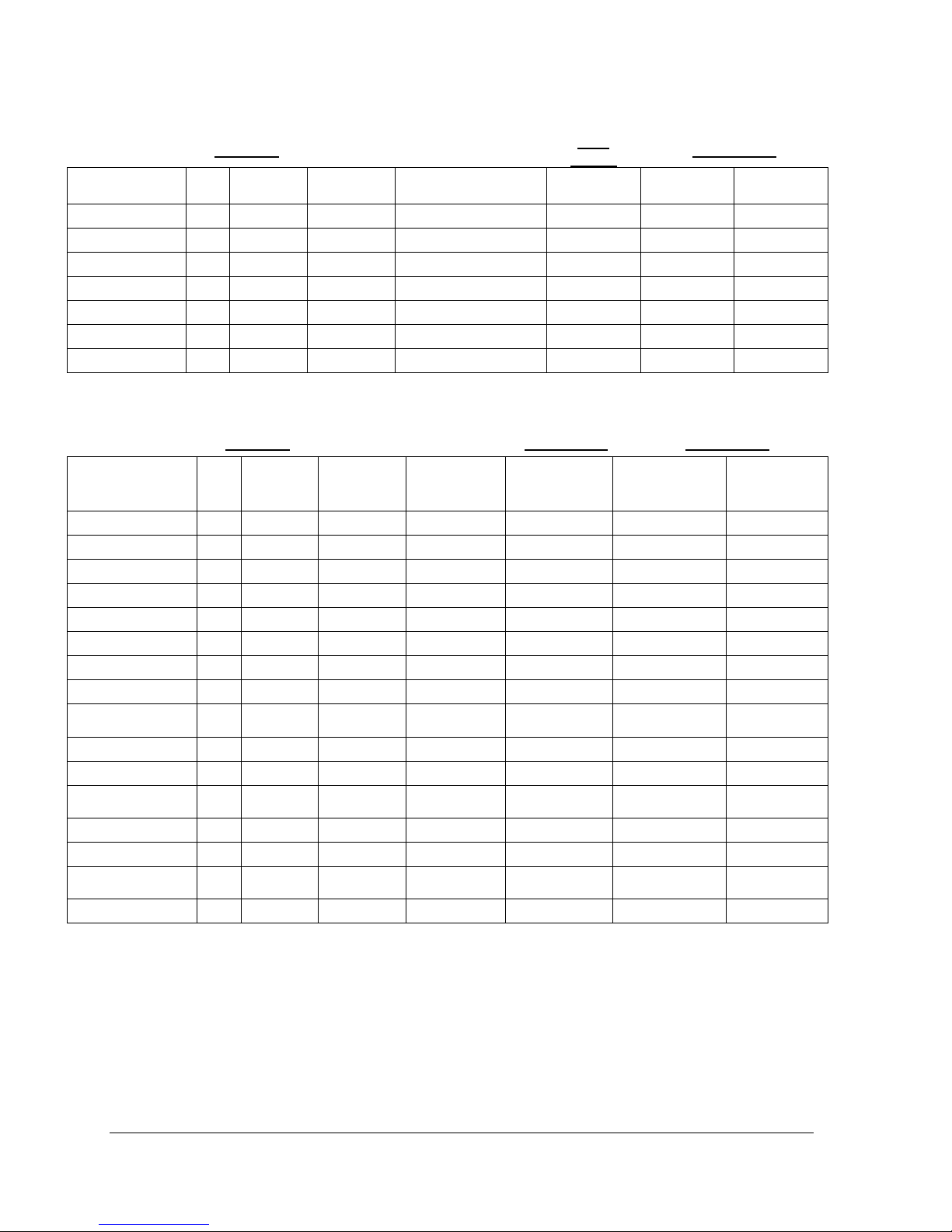
Table 4 : VOLTMAX 240 VAC / 60 Hz / 3 Phases1
1
Electrical supply 240 V - 1 phase (L1-L2) with 2 conductors 90°C with a ground.
Table 5 : VOLTMAX 480 VAC / 60 Hz / 3 Phases1
1
Electrical supply 480 V - 1 phase (L1-L2-L3) with 3 conductors 90°C with a ground.
VOLTMAX ELECTRIC BOILER Installation and Operation Manual (Revised August 2017), Page 5.
Capacity
STG Series
SCR Series
Model
kW
BTU/h
Amps
Electrical
element(s)
240 V
Stage Relay
Model
kW
VOLTMAX 30
30
102 360
28,9
6 x 5 kW
2 x 15 kW
1 x 15 kW
1 x 15 kW
VOLTMAX 36
36
122 832
34,6
6 x 6 kW
2 x 18 kW
1 x 18 kW
1 x 18 kW
VOLTMAX 45
45
153 540
43,3
9 x 5 kW
3 x 15 kW
2 x 15 kW
1 x 15 kW
VOLTMAX 54
54
184 248
52
9 x 6 kW
3 x 18 kW
2 x 18 kW
1 x 18 kW
VOLTMAX 60
60
204 720
57,7
12 x 5 kW
4 x 15 kW
3 x 15 kW
1 x 18 kW
VOLTMAX 72
72
245 664
69,3
12 x 6 kW
4 x 18 kW
3 x 18 kW
1 x 18 kW
VOLTMAX 75
75
255 900
72,2
15 x 5 kW
5 x 15 kW
4 x 15 kW
1 x 15 kW
VOLTMAX 90
90
307 80
86,6
15 x 6 kW
5 x 18 kW
4 x 18 kW
1 x 18 kW
VOLTMAX 99
99
337 788
95,3
9 x 5 kW +
9 x 6 kW
3 x 33 kW
2 x 33 kW
1 x 33 kW
VOLTMAX 108
108
368 496
103,9
18 x 6 kW
3 x 36 kW
2 x 36 kW
1 x 36 kW
VOLTMAX 120
120
409 440
115,5
24 x 5 kW
4 x 30 kW
3 x 30 kW
1 x 30 kW
VOLTMAX 132
132
450 384
127
12 x 5 kW +
12 x 6 kW
4 x 33 kW
3 x 33 kW
1 x 33 kW
VOLTMAX 144
144
491 328
138,6
24 x 6 kW
4 x 36 kW
3 x 36 kW
1 x 36 kW
VOLTMAX 150
150
511 800
144,3
30 x 5 kW
5 x 30 kW
4 x 30 kW
1 x 30 kW
VOLTMAX 165
165
562 980
158,8
15 x 5 kW +
15 x 6 kW
5 x 33 kW
4 x 33 kW
1 x 33 kW
VOLTMAX 180
180
614 160
173,2
30 x 6 kW
5 x 36 kW
4 x 36 kW
1 x 36 kW
VOLTMAX
90 kW and less
More than 90 kW
Maximum operating pressure
30 PSI
60 PSI
Optional maximum operating pressure
70 PSI*
125 PSI
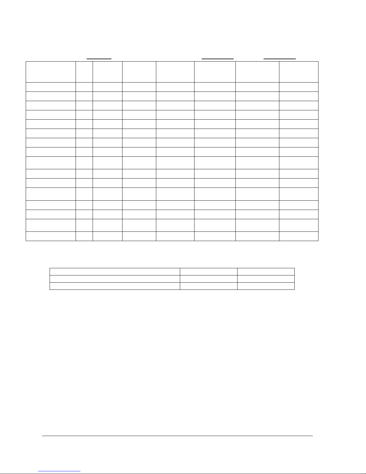
Table 6 : VOLTMAX 600 VAC / 60 Hz / 3 Phases1
1
Electrical supply 600 V - 1 phase (L1-L2-L3) with 3 conductors 90°C with a ground.
Tableau 7 : Maximal service pressure
* Model from 23 to 90 kW are available at a maximum operating pressure of 125 PSI, but size of the unit will be the
same as model of more than 90 kW.
VOLTMAX ELECTRIC BOILER Installation and Operation Manual (Revised August 2017), Page 6.
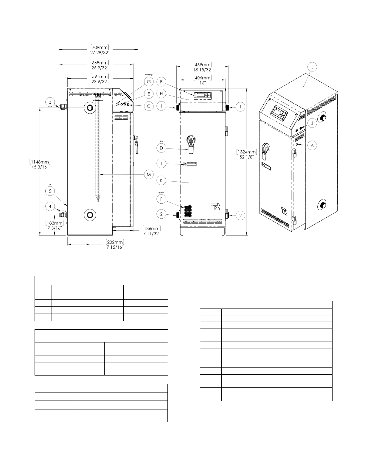
BOILER CONNECTIONS
1
Boiler outlet
1 1/2" NPT M
2
Boiler inlet
1 1/2" NPT M
3
Pressure relief valve
3/4" NPT F
4
Drain valve
3/4" NPT F
5*
Access to the return sensor
1/2" NPT F
MIN. CLEARANCES FOR INSTALLATION &
MAINTENANCE
Left and Right sides
3"/ 76mm
Rear
3"/ 76mm
Front
24" / 610mm
Bottom
0" / 0mm
Top
32" / 813mm
GENERAL INFORMATIONS
Weight
310lbs / 141kg
Water Volume
11 Us gal. / 41.6 liters
Max. operating
pressure
STANDARD: 30psi
OPTION: 70 PSI *
COMPONENTS IDENTIFICATION
A
Electrical main supply
B
Boiler controller
C
"On/Off" switch
D**
Disconnect switch & rotary handle
E
Fuses for controls
F***
Solid state SCR relay
G****
Low water cut-off, test button and indicator
lights
H
Electrical control access door
I
Door handle for electric access with lock
J
Electrical control wires access holes
K
Access door power circuit
L
Access cover to Heating elements
M
Heating elements
BOILER DIMENSIONS AND CHARACTERISTIC: MODELS 90KW OR LESS
* Return sensor available with the " SCR SERIES " configuration.
** Optional disconnect switch available on " THREE-PHASE " models.
*** Solid state SCR relay available with the " SCR SERIES " configuration.
**** Low water cut-off is optional.
*Available at 125PSI (See Shop Drawing 99-180KW)
VOLTMAX ELECTRIC BOILER Installation and Operation Manual (Revised August 2017), Page 7.
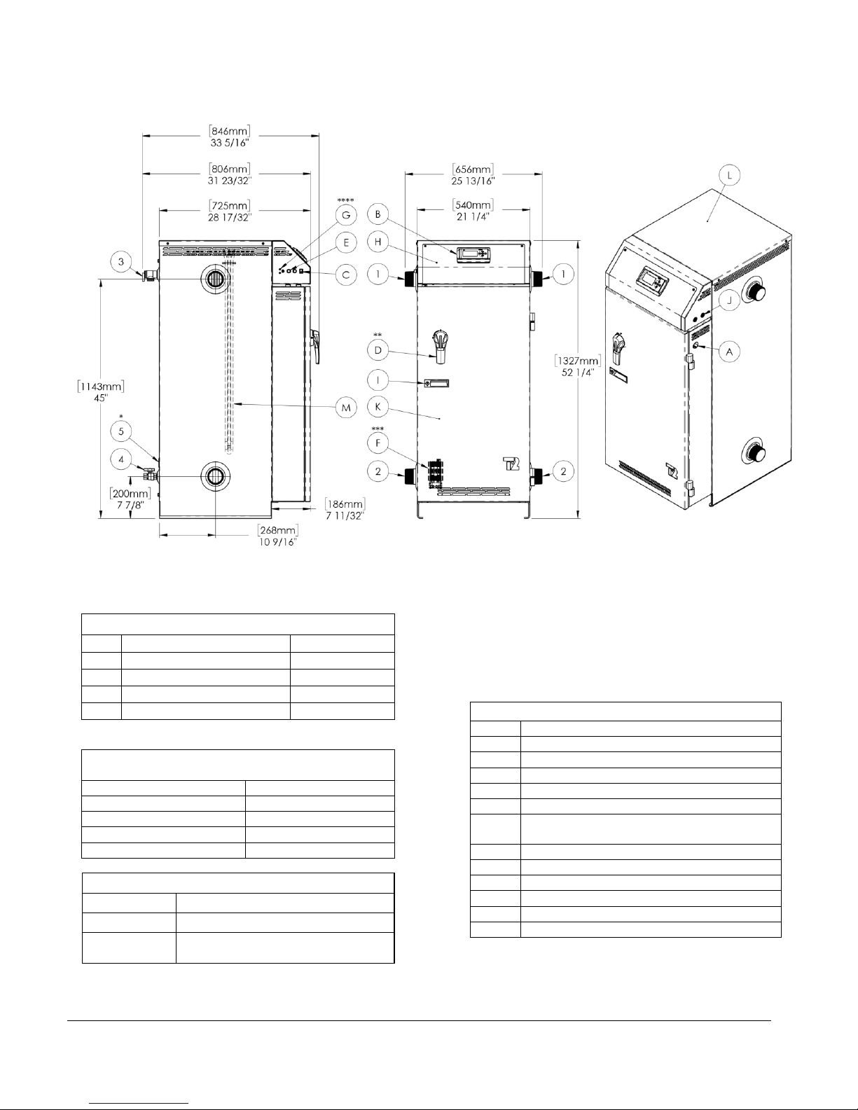
BOILER CONNECTIONS
1
Boiler outlet
1 1/2" NPT M
2
Boiler inlet
1 1/2" NPT M
3
Pressure relief valve
3/4" NPT F
4
Drain valve
3/4" NPT F
5*
Access to the return sensor
1/2" NPT F
MIN. CLEARANCES FOR INSTALLATION &
MAINTENANCE
Left and Right sides
3"/ 76mm
Rear
3"/ 76mm
Front
24" / 610mm
Bottom
0" / 0mm
Top
32" / 813mm
GENERAL INFORMATIONS
Weight
550lbs / 250kg
Water Volume
30 gal. Us/ 113.5 liters
Max. operating
pressure
STANDARD: 60psi
OPTION: 125 PSI
COMPONENTS IDENTIFICATION
A
Electrical main supply
B
Boiler controller
C
"On/Off" switch
D**
Disconnect switch & rotary handle
E
Fuses for controls
F***
Solid state SCR relay
G****
Low water cut-off, test button and indicator
lights
H
Electrical control access door
I
Door handle for electric access with lock
J
Electrical control wires access holes
K
Access door power circuit
L
Access cover to Heating elements
M
Heating elements
BOILER DIMENSIONS AND CHARACTERISTIC: MODELS 90KW TO 180KW
* Return sensor available with the " SCR Series " configuration.
** Optional disconnect switch
*** Solid state SCR relay available with the " SCR Series " configuration.
**** Low water cut-off is standard for models 120 kW and more.
VOLTMAX ELECTRIC BOILER Installation and Operation Manual (Revised August 2017), Page 8.
List of components shipped with the unit:
• Pressure relief valve
• Drain valve
• Outdoor temperature sensor ¸
(Located inside the control panel of the
unit)
!
AVERTISSEMENT
!
WARNING
!
General Safety Precautions
Be sure to read and understand the entire Installation & operation manual before attempting to install or to operate this water
heater. Pay attention to the following General Safety Precautions. Failure to follow these warnings could cause property damage,
bodily injury or death. Should you have any problems understanding the instructions in this manual, STOP, and get help from a
qualified installer or technician
SECTION 2 : INTRODUCTION
These important safeguards and instruction appearing in this manual are not meant to cover all
possible conditions and situations that may occur. Common sense,
caution and care are factors that cannot be built into every product. These factors must be
supplied by the person(s) caring for and operating the unit.
2.1 LOCAL INSTALLATION
REGULATIONS
This electric boiler must be installed in
accordance with these instructions and in
conformity with local codes, or in the absence of
local codes, with the National Plumbing Code
and the National Electric Code, current edition.
In any case where instructions in this manual
differ from local or national codes, the local or
national codes take precedence.
2.2 CORROSIVE ENVIRONMENT
The electric boiler must not be installed near an
air duct supplying corrosive atmosphere or with
high humidity content. When a boiler defect is
caused by such conditions, the warranty will not
apply.
2.3 INSPECTION UPON RECEPTION
Inspect the electric boiler for possible shipping
damage. The manufacturer’s responsibility
ceases upon delivery of goods to the carrier in
good condition. The Consignee must file any
claims for damage, shortage in shipments, or
non-delivery immediately against the carrier.
2.4 TO BE CHECKED
Please refer to the rating plate on the unit to
ensure that you have the correct model and
voltage in hand.
The electric boiler should not be installed where it may damage the adjacent structures or lower
floors in the event of leakage of the tank or connections. If this cannot be avoided, install a nonflammable tray or bowl under the boiler to collect and drain water from leaks.
NOTE: Any tray or cuvette MUST conform to local codes.
VOLTMAX ELECTRIC BOILER Installation and Operation Manual (Revised August 2017), Page 9.

Sides**
3 inches / 76 mm
Bottom
0 inches / 0 mm
Top*
32 inches / 813 mm
Front
24 inches / 610 mm
Back
3 inches / 76 mm
MISE EN GARDE
!
SECTION 3 : INSTALLATION
The manufacturer’s warranty does not cover any damage or defect caused by installation, or
attachment, or use of any special attachment other than those authorized by the manufacturer
into, onto, or in conjunction with the water heater. The use of such unauthorized devices may
shorten the life of the boiler and may endanger life and property. The manufacturer disclaims any
responsibility for such loss or injury resulting from the use of such unauthorized devices
3.1 SAFETY MEASURES
Any commercial installation will be equipped with
a safety valve that limits the maximum working
pressure to the maximum design pressure of the
tank. The maximum operating pressure of the
VOLTMAX Boiler with a power of 90kW and less
is 30 psi or 70 psi, depending on the options
chosen. The maximum operating pressure of the
VOLTMAX boiler with a power of more than
90kW is 60 psi or 125 psi, depending on the
options selected. See boiler data sheet for
maximum operating pressure.
The boiler is equipped with an automatic high
limit temperature control set at 210°F (99°C) and
a second manual high limit temperature settable.
This electric boiler is designed to operate at a
maximum operating temperature of 200 ° F (93 °
C). The boiler is designed for use in a hot water
heating system only.
The heat transfer fluid must be water or an
antifreeze water / propylene glycol solution or
an antifreeze water / ethylene glycol solution
specially designed for heating systems. The
maximum concentration of solution must be a
maximum of 50%.
3.2 LOCATION
The electric boiler should be installed in a clean,
dry location. Long hot water lines should be
insulated to conserve water and energy. The
electric boiler and water lines should be protected
from exposure to freezing temperature.
The boiler can be mounted vertically or
horizontally directly on a solid surface.
The electric boiler must be located or protected
to avoid risk of physical damage, such as from
moving vehicles, flooding, etc.
The location must have sufficient ventilation to
maintain an ambient temperature not exceeding
80°F (27°C).
To prevent condensation on the boiler walls,
boiler temperature should not be maintained
below the condensation temperature (dewpoint temperature) of the ambient. The
operating temperature of the boiler must not
be lower than the condensation temperature
(dew temperature) relative to the ambient
humidity content.
3.3 CLEARANCES
For adequate inspection and servicing the
following minimum clearance is necessary:
Table 8 : Boiler Clearances
* A minimum clearance of 32 inches. For units
equipped with 18 kW elements (25 in. For 15 kW
elements) is required for possible replacement of
heating elements.
** The left side of the control panel, where the
boiler ON / OFF switch is located, must
remain visible after installation. Otherwise, a
label indicating its location must be affixed to
the control panel indicating its position.
3.4 PIPING INSTALLATION
The location of the inlet and outlet piping shall
conform to the various configurations shown in
Figure 1. You will find typical connection
diagrams to the Figure 3, Figure 4 and Figure 5.
The VOLTMAX boiler is designed to be
operated on a closed circuit piping system.
Therefore, it should not be used to heat open
air tanks
VOLTMAX ELECTRIC BOILER Installation and Operation Manual (Revised August 2017), Page 10.
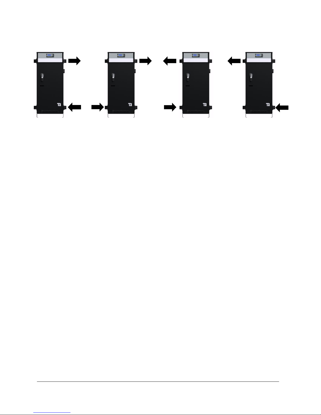
Figure 1 : Possible pipe flow configurations
3.4.1 BOILER PIPING CONNECTION
The boiler is equipped with two fittings on each
side of the unit. One of the bottom connections
must be used for the heating return (inlet) and
one of the top connections must be used for
supplying the heating system (outlet).
The outlet and inlet size are 1½ "NPTM threaded
steel pipes, for the VOLTMAX with a power of
90kW and less and 2½ "NPTM threaded steel
pipes for the VOLTMAX with a power of More
than 90kW.
Installation of plugs on the inlet and exhaust
ducts is required to facilitate the disconnection
and maintenance of the boiler.
When connecting different types of pipes
(galvanized steel and copper), use dielectric
joints (insulation) to protect the boiler and piping.
Use only new and clean pipes as piping
connection to the boiler. Local codes or
regulations may dictate the exact type of material
to be used.
Insulate all piping containing hot water, especially
in an unheated environment.
Install faucets for easy maintenance.
Install a thermometer on the inlet and outlet
duct(s).
Close the unused openings on the boiler. Do not
block the safety valve, this may cause loss,
damage or injury.
3.4.2 AUXILIARY BOILER PIPING
CONNECTION
When an auxiliary boiler used as back up is
twinned to the VOLTMAX boiler to act as a backup controlled by the VOTLMAX, the auxiliary
boiler shall be installed downstream of the
electric boiler as shown on Figure 5 and 7.
3.4.3 SAFETY VALVE
The installation of a safety valve is an integral
part of the boiler’s installation. The trigger point of
the valve must not exceed the design pressure of
the boiler as indicated on its registration and
identification plate. The valve must comply with
the ASME Boiler and Pressure Vessel Code and
limit the boiler maximum operating pressure. The
safety valve is a security component, not a
control component.
The capacity of the safety valve expressed in
BTU / hour must equal or exceed the rating on
the nameplate of the boiler (s).
A safety valve adjusted to the maximum design
pressure of the boiler has been installed at the
factory. The latter can be replaced by a valve with
a lower trigger pressure, but its BTU / hour
capacity must not be lower than the maximum
boiler power.
Connect the exhaust of the safety valve to a drain
line. The lower end of this conduit shall be at
least 6" (15 cm) from the floor drain away from
any electrical component. The drain line must be
directed downwards from the exhaust of the
safety valve to ensure complete drainage by
gravity. The diameter of the drainpipe must not
be less than that of the exhaust of the valve. The
end of the conduit must not be threaded or
hidden and must be protected from freezing. No
VOLTMAX ELECTRIC BOILER Installation and Operation Manual (Revised August 2017), Page 11.

valves, valves or valves shall be installed on the
pipe. The installation of the safety valves is
governed by the local code.
3.4.4 SYSTEM PRESSURE CONTROL
AND EXPANSION TANK
Pressure control devices within the system
ensure that each component operates within
minimum and maximum allowable pressures and
maintain minimum pressure for all normal
operating temperatures. They also allow air
bleeding, prevent cavitation at the pump inlet and
prevent water from boiling within the system; all
this is accomplished with minimal addition of new
water.
The increase in boiler water volume resulting
from higher temperature is stored in the
expansion tank during periods of high operating
temperature and is returned to the system when
the temperature decreases.
The expansion tank must be able to store the
required volume of boiler water during maximum
design operating temperature without exceeding
the maximum allowable operating pressure, and
to maintain the required minimum pressure when
the system is cold. Contact your installing
contractor, plumbing supply house, or local
plumbing inspector for assistance. The point
where the expansion tank is connected should be
carefully selected to avoid the possibility that
normal operation of automatic check or manual
valves will isolate the tank from a hot boiler or
any part of the system.
The expansion tank should preferably be located
on the suction or intake side of the pump.
3.4.5 WATER PRESSURE MAKEUP
REGULATOR
Make-up systems must be employed as required
by codes. An automatic fill valve (automatic
pressure regulator) must be used with a backflow
preventer as required, to maintain minimum
system pressure by supplying water to make up
for leakage.
A minimum pressure of 5psi (34kPa) must be
maintained at all times.
A backflow prevention device that complies with
local standards must be installed upstream of the
pressure regulator.
3.4.6 AIR BLEEDER
The air contained in the heated water must be
removed from the system to allow the proper
functioning of the heating system and the boiler.
Installation of manual or automatic air vents is
required to eliminate all air from the boiler and the
heating distribution system.
The main air eliminator must be installed near the
outlet of the boiler on the highest point of the
main supply piping. It is imperative to ensure that
all air possibly located in the boiler be eliminated
at all time.
Regularly purge air from the pipes and beware
that the heated water does not cause injury or
damage.
If the boiler is located at a location higher than
the heat distribution system such as a heated
floor, an automatic air eliminator should be
installed close to the boiler outlet.
3.4.7 CIRCULATING PUMP
The pump capacity required is determined in
relation to the capacity of the boiler installed and
the type of heating distribution system on which it
will be connected.
They are generally designed for an operation at a
differential of temperature (Delta T0) of 10 to 20F
between the supplies and return temperature to
the boiler.
Use the following equation to determine the
required water flow.
Pump flow rate = Boiler power ÷ Delta T ÷ 500
Pump flow rate is expressed in US gallons
per minute or GPM.
The Boiler output (in net BTU per hour) is the
maximum amount of heat to be transferred
through the heating loop to meet the heating
load.
Delta T: The boiler water temperature drop
For example, an electric boiler rated at 180KW
has an output capacity of 614 160 BTU per hour.
The system is designed for a temperature drop of
20°F.
Required pump flow rate = 614,160 20 500 =
61,4 GPM
VOLTMAX ELECTRIC BOILER Installation and Operation Manual (Revised August 2017), Page 12.

MODEL
DELTA T0
10oF
20oF
30oF
40oF
VOLTMAX 23
15.7
7.8
5.2
3.9
VOLTMAX 27
18.4
9.2
6.1
4.6
VOLTMAX 30
20.5
10.2
6.8
5.1
VOLTMAX 36
24.6
12.3
8.2
6.1
VOLTMAX 40
27.3
13.6
9.1
6.8
VOLTMAX 41
28.0
14.0
9.3
7.0
VOLTMAX 45
30.7
15.4
10.2
7.7
VOLTMAX 48
32.8
16.4
10.9
8.2
VOLTMAX 50
34.1
17.1
11.4
8.5
VOLTMAX 54
36.8
18.4
12.3
9.2
VOLTMAX 55
37.5
18.8
12.5
9.4
VOLTMAX 60
40.9
20.5
13.6
10.2
VOLTMAX 66
46.4
23.2
15.5
11.6
VOLTMAX 68
45.0
22.5
15.0
11.3
VOLTMAX 72
49.1
24.6
16.4
12.3
VOLTMAX 75
51.2
25.6
17.1
12.8
VOLTMAX 90
61.7
30.8
20.6
15.4
VOLTMAX 99
67.8
33.9
22.6
17.0
VOLTMAX 108
73.7
36.8
24.6
18.4
VOLTMAX 120
82.2
41.1
27.4
16.1
VOLTMAX 132
90.5
45.2
30.2
22.6
VOLTMAX 144
98.7
49.3
32.9
24.7
VOLTMAX 150
102.4
51.2
34.1
25.6
VOLTMAX 165
112.6
56.3
37.5
28.1
VOLTMAX 180
122.8
61.4
40.9
30.7
For example, an 180kW electric boiler has a
power of 614,160 BTU/h. The system is designed
for a drop-in temperature (Delta T) of 20°F.
Flow required = 614,160 20 500 = 61.4 GPM
N.B. To achieve proper operation, a minimum
flow must be present when a heating request is
applied and the heating elements are in
operation. See the table below for the
recommended minimum flow depending on the
boiler output. Installation of a flow switch is not
mandatory
The following table lists the required pump flow
rate in relation to the boiler capacity and Delta T.
Table 9 : Temperature rise vs flow rate
(GPM)
3.4.8 DRAIN FAUCET
A drain valve is installed behind the unit. It allows
the boiler to be emptied, to make possible the
replacement of defective components.
VOLTMAX ELECTRIC BOILER Installation and Operation Manual (Revised August 2017), Page 13.
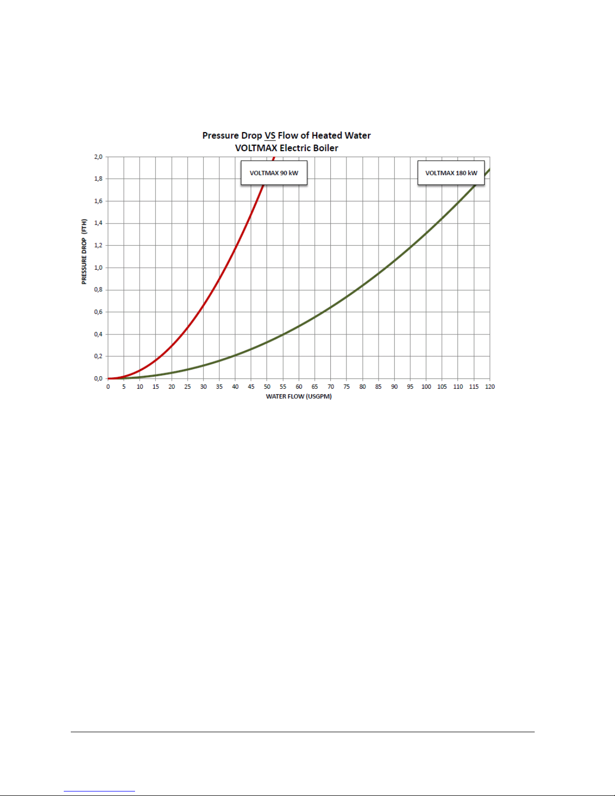
3.4.9 PRESSURE LOSS
The graph of pressure loss due to flow of water inside the VOLTMAX boiler is shown in the following figure.
Figure 2 : Pressure loss (FTH) as a function of the flow rate of heated water (GPM)
VOLTMAX ELECTRIC BOILER Installation and Operation Manual (Revised August 2017), Page 14.
VOLTMAX ELECTRIC BOILER Installation and Operation Manual (Revised August 2017), Page 15.
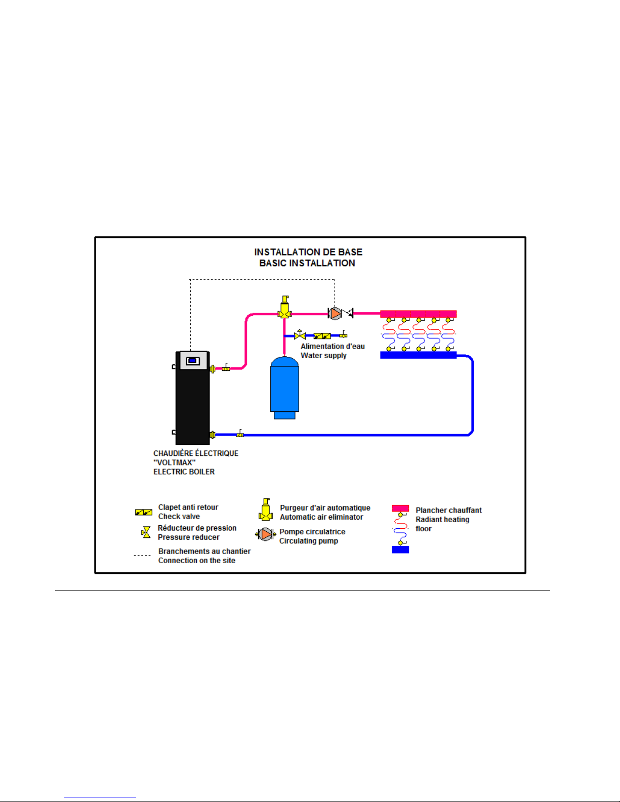
Figure 3 : Basic installation
VOLTMAX ELECTRIC BOILER Installation and Operation Manual (Revised August 2017), Page 16.
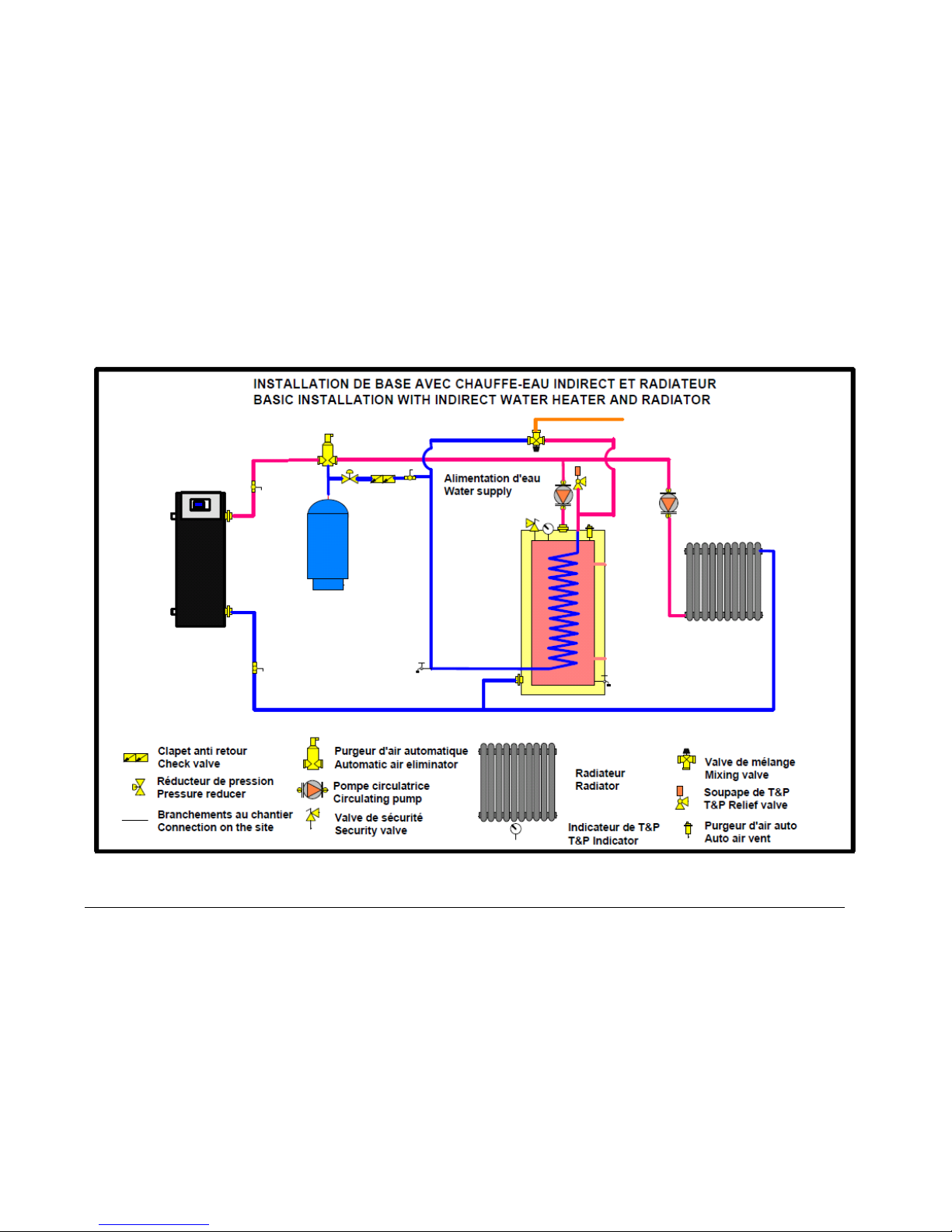
Figure 4 : Basic installation with indirect water heater and radiator
VOLTMAX ELECTRIC BOILER Installation and Operation Manual (Revised August 2017), Page 17.
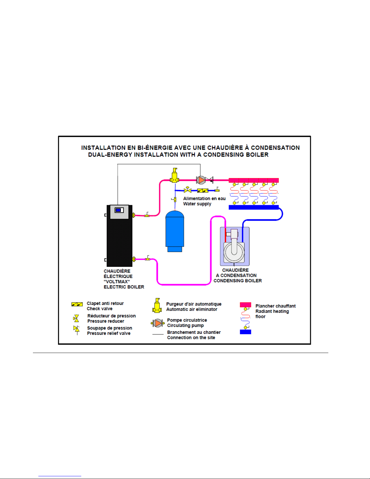
Figure 5 : Dual-Energy installation with a condensing boiler
VOLTMAX ELECTRIC BOILER Installation and Operation Manual (Revised August 2017), Page 18.
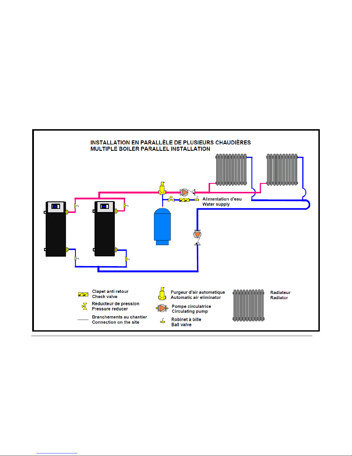
Figure 6 : Multiple boiler parallel installation

VOLTMAX ELECTRIC BOILER Installation and Operation Manual (Revised August 2017), Page 19.
Figure 7 : Basic installation with auxiliary boiler for production of domestic hot water and heating

3.5 ELECTRICAL CONNECTIONS
Wiring must be conform to the National Electrical
Code and to state or local code requirements.
The electric boiler must be electrically grounded
in accordance with local codes, or, in the
absence of local codes, with the National
Electrical Code.
3.5.1 MAIN ELECTRICAL SUPPLY
The power supply must be a 208 or 240-volt
circuit (single-phase or three-phase, 60Hz), 480
volts (three-phase, 60 Hz) or 600 volts (threephase, 60 Hz) protected by an appropriately
sized breaker.
Refer to the boiler rating plate to select the
breaker capacity and wiring rating
3.5.2 PUMP SUPPLY
The VOLTMAX Electric boiler (SCR models) can
control 1 or 2 pumps of the distribution system.
According to the VOLTMAX configuration, the
contact of the pump will function differently.
During a heat demand on W1 or W2, the contact
between Pc and P1 or Pc and P2 will be used to
start an external pump relay (maximum of 3
amps.). Depending on the configurations selected
in the controller, the pump P2 can have priority
over the pump P1.
N.B. The VOLTMAX boiler is not designed to
heat without a water circulation in its tank.
Therefore, if external pump controls are used,
they must be interlocked with the operating
authorization on W1or W2 of the controller.
3.5.3 CONNECTION OF EXTERNAL
SIGNALS TO THE CONTROLLER
The connection of all external signals is made
directly on the boiler controller on terminals
located on top of it. See the connection diagram
on
Figure 8 and Figure 9.
Cables used for the connections shall resist
temperature up to 90 °C.
3.5.3.1 Connecting the building heat demand
signal
Upon reception of a closed contact connected to
terminals 24V+ and W1 or W2, the corresponding
circulating pump P1 or P2 will start and the boiler
will be allowed to operate.
If external controllers control the heating system
pumps, they must provide the operating
authorization signal. The boiler must not receive
a heat demand without the circulation pumps
running.
On heating systems when water circulation is
continuous, the heat demand control can be
connected to the 24V+ and W1 terminals. The
heating elements will then be active and available
only when there is a request (dry contact).
If the heating system is designed to keep water
warm with continuous circulation, a jumper
(jumper) must be installed on the 24V+ and W1
terminals to maintain the boiler in demand. The
boiler will then attempt to maintain the water
temperature at the set-point.
Operation with an upper fixed set-point W2 can
be established by connecting the auxiliary
heating demand signal (Dry contact) of a
thermostat to the 24V+ and W2 of the terminal
block.
In all operating modes of the controller, a heat
demand on W1 and W2/DHW (close contact)
must be present to DI1 or DI2 to allow the
operation of the boiler. The only exception is in
domestic hot water mode (DHW) with an indirect
water heater where the minimum boiler
temperature shall be maintained.
3.5.3.2 Connecting au auxiliary boiler
(Available only on SCR models)
The boiler controller is designed to allow the
operation of a second boiler or an auxiliary boiler
according to two different mode of operation
“Auxiliary Backup” or Dual-Energy”.
To do so, connect the TT terminals of the
auxiliary boiler to terminals AUX of the
VOLTMAX. The maximum capacity of this
contact is 3A/120Vac.
See section 3.4.5 for details.
VOLTMAX ELECTRIC BOILER Installation and Operation Manual (Revised August 2017), Page 20.

3.5.3.3 Connection of an “Unoccupied signal”
of the building.
This function allows dropping the boiler
temperature during periods where the building is
not used and this without having to lower all the
room thermostats of the building.
To do so, a signal (dry contact) will have to be
connected to terminal OCC. (SCR model only)
The contact shall be close during the periods of
temperature drop.
You can also manage the periods of temperature
drop by setting a schedule in the controller.
3.5.3.4 Connection of an indirect domestic
hot water heater
The VOLTMAX electric boiler can be used not
only to fill the heating requirements of the building
but also to fill its domestic hot water needs using
an indirect domestic hot water heater such as our
TURBOMAX series.
To do so, connect the signal (dry contact) of
indirect water heater temperature control to the
terminal 24V+ and W2/DHW (SCR model only.
This will activate the circulating pump supplying
the water heater (if properly installed).
On STG models, the pumps can be controlled by
an external pump controller with the same
characteristics
3.5.3.5 Connection of a dual-energy signal
(SCR model only)
The VOLTMAX can be operated in a dual-energy
mode with an auxiliary boiler.
To do so, connect the normally close contact of
the dual energy controller to terminals 24V+ & BI-
E to operate with the electric boiler. See section
4.3.4.5 for more details on the sequence of
operation in dual energy.
3.5.3.6 Connection of an outdoor temperature
sensor
If you wish to modulate the boiler water
temperature according to the outdoor
temperature (Outdoor Reset, ORST) and also
wish to stop the operation of the boiler when the
outdoor temp. reaches a selected value, then the
outdoor sensor supplied with the unit or a
corresponding signal coming from the network
system shall be connected with a cable of
minimum gauge 20 (max 100pi) to terminals S.
Ext. of the controller.
This probe does not need to be connected during
an operation with a fixed setpoint temperature
unless you want to use the Warm weather
Shutdown function.
N.B. Do not install a jumper if the outside sensor
is not used.
Outdoor sensor location
o Outside the building at a location that best
represents the heat demand of the building (a
wall facing north for most of the buildings and
on a south one on buildings with large
windows facing south).
o It should not be exposed to external heat
sources (dryer outlet, window openings, noninsulated walls).
o It should not be installed in a location where it
could be covered with snow.
3.5.3.7 Remote controller used to determine
the target boiler temperature (SCR model
only)
An external controller (such as a central building
energy management system) can be used to
determine the boiler target temperature required
for the building. To do so, the external controller
shall give a 0 to 10VDC signal connected to
terminals 0-10Vdc G & 0-10Vdc T° of the
controller.
3.5.3.8 Limit Capacity 0-10VDC (SCR model
only)
An external controller providing a 0-10Vdc signal
could be used to manage the capacity (kW) of the
boiler.
Example: An application where the main
electrical service supply of the building is limited
or when the electricity rate is billed according to
the maximum peak loads of the building. To do
so, the external controller shall be connected to
terminals 0-10Vdc G & 0-10V cap. The capacity
of the boiler could be manually limited by
adjusting some of the controller parameters. See
section 4.3.4 for more details.
3.5.3.9 External alarm contact (SCR model
only)
An alarm signal (dry contact) is available on the
boiler to advise the user of an alarm situation.
The capacity of the contact is 3A resistive/1A
inductive on terminal AL/AL.
An internal audible alarm inside the controller is
available on all models. Just activate it in the
settings.
VOLTMAX ELECTRIC BOILER Installation and Operation Manual (Revised August 2017), Page 21.

VOLTMAX ELECTRIC BOILER Installation and Operation Manual (Revised August 2017), Page 22.
Figure 8 : ELECTRICAL CONNECTIONS OF THE INPUT AND OUTPUT SIGNALS TO THE CONTROLLER (SCR MODEL)
Figure 9 : ELECTRICAL CONNECTIONS OF THE INPUT AND OUTPUT SIGNALS TO THE CONTROLLER (STG MODEL)

W1
Heating request 1 : On
W2
Heating request 2 : On
P1
Pump 1 : On
P2
Pump 2 : On
BIE
Boiler in Bi-Energy mode
VOLTMAX Boiler : On
Auxiliary boiler : On
Boost mode : On
Warm Weather Shut Down : On
An alarm is active
The boiler is in lock out mode
HL
High temperature limit condition at
the boiler outlet
LL
Low temperature limit conditions
(lack of capacity)
P
Alarm due to a pressure problem
A
Alarm due to an electrical problem
F
Alarm due to a flow problem
Se
Alarm due to a sensor problem
T° SETPOINT
Actual set-point temperature
T° BOILER
Water temperature at the
outlet of the boiler
CAP (%)
Percentage of power used
according to boiler rated
power
T° EXT
Outdoor temperature
measured using the outdoor
sensor
KW ACT
Actual power calculated by
the boiler
PRESS.
Pressure inside the boiler
STAGE
Status of active stage
SECTION 4 : CONTROLLER OPERATION
4.1 USER INTERFACE
The control of the boiler is ensured by a
controller TM171PFE03 of the company
Schneider Electric. The LCD display of the
controller provides an interface for configuring
and displaying the boiler parameters.
A communication module also allows you to
integrate the controller with an intelligent building
management system (BACnet protocol). It is
also equipped with an Ethernet connection.
Allowing the connection to the Internet network
of the building allowing to read and modify
locally or remotely the boiler setting. It can be
configured to send alarm messages via e-mail.
Icons will also display to indicate the boiler’s
current operating status. Temperature can be
displayed in Celsius or Fahrenheit and text can
be set to either English or French.
The controller has a backlight function. It is also
equipped with three indicator lights (Green /
Yellow / Red). The green light indicates normal
operation of the unit; the yellow light indicates
that the controller has diagnosed and anomaly
which requires verification by a technician. The
red light indicates that the unit is currently in a
critical state (high temperature alarm) or in lock
out mode. More detail is provided in Section 6:
Troubleshooting. The controller can also be
configured to activate an internal buzzer and
activate an external alarm signal (SCR only)
when an alarm condition occurs causing the
boiler to fail.
Boiler operating mode
Alarm symbol
Operating state of the boiler
Figure 10 : Illustration of the display
4.1.1 SYMBOL DESCRIPTION
The main display shows most the boiler
operation status information. The explanation of
the main display is shown below.
VOLTMAX ELECTRIC BOILER Installation and Operation Manual (Revised August 2017), Page 23.

1
2 3 4
4.1.2 CONTROL PANEL
Figure 11 : Control panel
On the left side of the appliance, an on / off
switch (# 3) is used to operate the appliance and
to reset the boiler.
An indicator light showing the status of the low
water level cut off and a test button (# 1) is
standard for models 120 kW and above. The
control circuit fuses (# 2) are accessible from the
left side of the unit.
4.1.3 NAVIGATION AND
ADJUSTEMENTS
The navigation within the display is done with
the five pushbuttons on the right of the screen.
Navigation between the elements is done with
the up and down arrows. Use the right key to
change the page in the menus. The return key
will bring you to the previous menu. The return
key returns you to the main display when it is
pressed for 2 seconds or more.
The OK button confirms the selection and allows
you to edit a parameter. Only highlighted box
can be modified. To modify an option, select the
box to modify with the arrow keys and press OK.
The black box or one of its values will flash and
can be changed. Change the values using the
arrows and confirm the change by pressing OK.
VOLTMAX ELECTRIC BOILER Installation and Operation Manual (Revised August 2017), Page 24.

4.1.4 MAIN MENU NAVIGATION
Press one of the 5 buttons on the main display to access the main menu
VOLTMAX ELECTRIC BOILER Installation and Operation Manual (Revised August 2017), Page 25.
Figure 12 : Main menu navigation

4.1.5 NAVIGATION IN BOILER SETTING
Figure 13 : Navigation in boiler setting menu (1/3)
VOLTMAX ELECTRIC BOILER Installation and Operation Manual (Revised August 2017), Page 26.

You can switch from page by using the left or right arrow (Ex : 1/3 to 2/3 by using the
right arrow)
Figure 14 : Navigation in boiler setting menu (2/3)
VOLTMAX ELECTRIC BOILER Installation and Operation Manual (Revised August 2017), Page 27.

Figure 15 : Navigation in boiler setting menu (3/3)
VOLTMAX ELECTRIC BOILER Installation and Operation Manual (Revised August 2017), Page 28.

Menu
Contents
Boiler status
Detailed information on the
boiler condition
Boiler setting
Configuration of the boiler
operating mode and
parameters.
User setting
Configuration of the
controller display option
Clock setting
Configuration of the internal
clock
Consumption
Power consumption of the
boiler
Parameters
Description
Language
Select English or French
version
Temperature
unit
Select the temperature units,
either Celsius (C) or
Fahrenheit (F)
Flow unit
Select the flow unit, either US
gallons per minute (USgpm) or
liters per second (L / sec)
Backlight
Setting the backlight mode:
- Off
- 30 secondes
- Always On
Internal
buzzer
Setting of the internal buzzer
4.2 MAIN MENU
The main menu is accessible to the user, no
access code is required.
The main menu is accessed by pressing one of
the 5 pushbuttons. Navigation between menu is
done with the arrows (up, down, left and right).
4.2.2 BOILER CONFIGURATION
Configuration of the boiler operating mode
This menu is accessible only to the installer or to
an authorized person.
The options in the Boiler setting menu are
detailed in Section 4.3.
The Manufacturer access code gives access to
advanced operating parameters that are not
accessible to the installer and the user.
4.2.3 USER SETTING
Configuration of the controller display option
This menu allows the modification of different
display parameters.
4.2.1 BOILER STATUS
Detailed information on the boiler condition
This menu allows the display of data not
included in the main display. The boiler status
menu display the measurements of temperature,
pressure, flow, alarm summary, version of the
programme and the status of the heating
element.
The set of variables presented in this menu are
presented in Section 4.5
VOLTMAX ELECTRIC BOILER Installation and Operation Manual (Revised August 2017), Page 29.

HEATING
MODE W1
Boiler heating mode W1
configuration according to
the type of application
HEATING
MODE
W2/DHW
Boiler heating mode W2 or
DHW configuration according
to the type of application
PUMP
SETTING
Pump contact configurations
CAPACITY
LIMITING
Capacity limiting mode
configuration
AUXILIARY
BOILER
Auxiliary boiler mode
configuration (if needed)
4.2.4 CLOCK SETTING
Internal clock configuration
Use this menu to adjust the controller’s internal
clock. To set the clock correctly, you must adjust
the time, minutes, and date.
This adjustment is necessary in order for these
modes to function properly:
- The boiler’s power consumption
- Limiting the boiler’s power capacity according
to a schedule
- The boiler’s occupation mode
Battery life for the clock is at least 1 year when
the controller is unpowered (at 25°C).
N.B. The date and day of the week must be set
correctly to ensure the controller automatically
changes to daylight savings time.
4.2.5 CONSUMPTION
Boiler consumption cycle report
N.B. For the STG model, the calculation of
power consumption is based on a theoretical
approach, there may be differences between the
actual consumption of the boiler and the
consumption displayed on the screen.
N.B The consumption values are approximate
and should not be used as a comparison with
actual consumption data charged by the
electricity distributor.
4.3 BOILER SETTINGS
In order to be able to configure the boiler, it is
necessary to authenticate yourself with an
installer or manufacturer code.
The default "Installer" access code is
1111 and can be changed in the
Change password menu.
This menu allows visualization of the boiler
power consumption report. First, you must
activate the beginning of the consumption cycle
with the Start key. The consumption report can
be saved using the Save key. And all saved
report is available on the History tab. The
beginning of the consumption cycles can be
reset using the Reset button.
The controller records up to 30 consumption
report.
VOLTMAX ELECTRIC BOILER Installation and Operation Manual (Revised August 2017), Page 30.

LIMIT SETTING
Configuration of the
boiler operating limits
ALARM
Configuration of the
alarms
COMMUNICATION
Configuration of the
boiler communication
parameter (Web, Email,
Bacnet)
OCCUPATION
Configuration of the
occupation parameter
mode
MODE BOOST
Enable Boost mode
WARM WEATHER
SHUTD.
Enable warm weather
shut-down function
CHANGE
PASSWORD
Changing the Installer
password
FIXED
Fixed boiler set-point
DDC 010 VDC
Modulation of the boiler set-point
using a 0-10VDC signal
OUTD
RESET
Modulation of the boiler set-point
using the outdoor temperature
STOP
No heating demand on W1
4.3.1 HEATING MODE W1
Selection of the operating mode
In this menu you must select an operating mode
for selecting the desired setpoint temperature
depending on the application. A heat demand or
a demand must be present on W1 and/or
W2/DHW so that the boiler can heat up.
During a heat demand, the boiler activates
(depending on a PID curve) the number of
stages required in sequence so that the boiler
output temperature is maintained at the
approximate set-point temperature.
Here is the list of W1 heating modes:
4.3.1.1 Fixe
This mode is used for an installation where it is
desired to have a fixed set-point temperature.
If the boiler is thermostat-controlled with a heat
demand signal on W1, the boiler uses the
corresponding set-point (T. Set-point W1) as
the supply temperature.
4.3.1.2 DDC 0-10 VDC
(Available only on SCR model)
This operating mode allows modulating the
boiler set-point temperature according to a 010VDC signal applied the terminal 0-10VDC and
bornier 0-10Vdc G et 0-10Vdc T, produced by
an external controller (Ex: Building Energy
Management Controller).
The details of the parameters in this mode are
presented in Section 4.6.3.
4.3.1.3 Outdoor reset
This operating mode makes it possible to
modulate the boiler output set-point temperature
as a function of the outdoor temperature.
The outdoor temperature signal comes from the
temperature sensor supplied with the boiler,
which will be connected to the boiler controller.
The details of the parameters are presented in
Section 4.6.2 .
4.3.1.4 Stop
Select this mode to stop the boiler. The heating
elements will not operate on a W1 demand.
4.3.2 HEATING MODE W2/DHW
This mode allows you to configure a second
heating demand (W2) or a demand from an
indirect domestic water heater (DHW).
Select none if none of these functions are used.
These modes are presented in detail in Section
4.7.
W2
This mode allows the W2-DHW input to be used
to receive a signal (dry contact) from a 2nd
stage of heating.
When the contact on W2-DHW closes, the setpoint temperature changes to the set value (T.
Set-point W2), even if there is no demand on
W1.
DHW
This mode allows you to configure the demand
for an indirect domestic water heater. When the
DHW mode is selected, the boiler is kept at a
minimum temperature (T. Min Boiler) and when
contact W2 closes (Dry contact) the set-point
rises to T. DHW Set-point. In addition, the PID
curve is more aggressive.
VOLTMAX ELECTRIC BOILER Installation and Operation Manual (Revised August 2017), Page 31.

On W1 Dem.
Contact of pump 1 is activated
only when there is a demand
on W1.
On W2 Dem.
Contact of pump 2 is activated
only when there is a demand
in W2.
Priority over
P1
When there is a request on
W2, contact of pump 2 is
activated and contact of pump
1 is deactivated.
Always On
The selected pump is always
on (contact is always on).
Stop
The selected pump is always
deactivated (contact is always
off).
Off Delay
The delay in seconds before
the contact of the pump is
deactivated.
4.3.3 PUMP SETTING
Configuring pump contact activation
(Available only on SCR model)
The system allows the control of up to two
pumps. Each of these pumps can be activated
using a contact. Each pump can be activated
according to different modes.
If the amperage of each of the pumps exceeds
3A, external pump relays must be used.
Pump Configuration Options
N.B. External pump relays can also be used as
an alternative to the boiler pump controller. If this
alternative is used, a dry contact of this
controller must be connected to W1 or / and W2
to allow the boiler to operate only when there is
a flow of water present.
4.3.4 CAPACITY LIMITING
Adjusting the maximum authorized power
This menu allows you to configure the boiler
output limit. The selection of the limit mode can
be selected in the Capacity limiting menu
o None
o Manual
o DDC 0-10 VDC
o T. Ext
o Schedule
Details of each of these options are presented in
Section 4.9 .
N.B: It is not recommended to disconnect one of
the power relays inside the VOLTMAX boiler to
accomplish this function.
N.B: On the STG models, the maximum power
chosen must correspond to the power of the
stages of the boiler since there is no power
modulation relay on these models.
4.3.4.1 NONE
The boiler is not limited in power, the maximum
power it can deliver is equivalent to its maximum
rated power.
4.3.4.2 MANUAL
The maximum capacity permitted of the boiler is
configured in a fixed mode.
Details of the variables in this mode are
presented in Section 4.9.1
4.3.4.3 DCC 0-10 VDC
(Available only on SCR model)
A 0-10 VDC signal from a building management
system can be used. The signal is treated as a
function in order to limit the maximum power.
In order to configure this mode, you must
connect the 0-10 VDC signal to the terminal
block 0-10Vdc Cap. and 0-10Vdc G.
Details of the variables in this mode are
presented in Section 4.9.2
VOLTMAX ELECTRIC BOILER Installation and Operation Manual (Revised August 2017), Page 32.

None
No auxiliary boiler is present
Backup
Aux.
This mode allows the adjustment of a
second boiler to play a Backup role
Ext
Contact
Select the heating source using
electrical contact to the BI-E terminal.
BiE (BI-
Energy)
Select the heating source using
electrical contact to the BI-E terminal
with the possibility of support
mode of the auxiliary boiler.
Manual
Manually select the system operation
mode (Electrical or Auxiliary).
4.3.4.4 T. EXT
The maximum permitted power can be adjusted
according to the outside temperature sensor.
The outdoor temperature is used in order to limit
the maximum authorized power.
Details of the variables in this mode are
presented in Section 4.9.3 .
This mode of operation is particularly
advantageous in applications where the
boiler is connected to an electrical network
taking account of demand peaks in order to
determine the cost of use (demand meter).
Since the boiler will thus be limited to a
maximum power which will have to be
established as a function of the heating
requirements of the building and the outside
temperature, it will thus be possible to avoid
peaks of power not required to satisfy the
heating needs in periods of cold weather.
4.3.4.5 Schedule
The maximum authorized boiler power can be
programmed according to a schedule. See
section 4.9.4 for an explanation of how to
modify a schedule.
4.3.5 AUXILIARY BOILER
(Available only on SCR model)
The controller program has been designed to
allow the operation of a second boiler or
auxiliary boilier.
4.3.5.1 Select setpoint source for Auxiliary
Boiler
The source of the set-point temperature control
can be configured by selecting STPT source
Aux. consequently.
In the Internal mode, the terminal contact Aux
closes when there is a request for W1 or
W2/DHW and the VOLTMAX output temperature
is below the setpoint temperature. In addition,
the Aux contact is opened when the output
temperature is higher than the setpoint
temperature.
In External mode, the Aux contact closes when
there is a request on W1 or W2 / DHW
regardless of the boiler output temperature
VOLTMAX. The VOLTMAX boiler thus has no
set temperature and is only used to activate the
auxiliary boiler relay.The various configurations
of the Aux boiler mode are the following:
N.B. The auxiliary boiler can only be switched on
when a heat demand is present on W1 or / and
W2 / DHW.
4.3.5.2 None
This mode must be active when there is no
auxiliary boiler on the hydronic heating system.
4.3.5.3 Backup Aux.
The boiler will be activated according to the
configuration of the lack of capacity of the
VOLTMAX boiler.
In the event of a lack of capacity, the boiler is
started to compensate.
The lack of capacity is defined by the fact that
the boiler output temperature is less than X
degrees (Delta T. Start Aux.) relative to the setpoint for duration of X min. (Auxiliary Start
Delay). The auxiliary boiler will be deactivated
when the temperature differential between the
water outlet temperature and the set-point
temperature is lower than Delta T. Off Aux. The
calculation of the delay begins only when the
electric boiler reaches its maximum power (or
maximum power allowed).
The value of "Delta T." should be a negative
value.
Details of the variables in this mode are
presented in Section 4.10.1
VOLTMAX ELECTRIC BOILER Installation and Operation Manual (Revised August 2017), Page 33.

An alarm is active
The boiler is in lock mode
HL
The high limit temperature has been
reached
LL
Low limit (Lack of capacity)
P
Pressure problem alarm
A
Electrical problem alarm
F
Flow problem alarm
Se
Sensor problem alarm
4.3.5.4 Contact Ext.
This configuration mode makes it possible to
operate the electric boiler or the auxiliary boiler
according to a contact. During a close contact at
the BI-E terminals, the electric boiler ( ) is
activated. When the contact is open, the
auxiliary boiler ( ) will be on. The auxiliary
boiler will not be allowed to operate if the electric
boiler lacks capacity.
Details of the variables in this mode are
presented in Section 0
4.3.5.5 BiE (BI-Energy)
The Bi-Energy mode allows the auxiliary boiler
to operate when there is a lack of capacity.
Upon receipt of an electrical signal (contact
closed at Bi-E) and a request at the terminal of
W1 or W2, the contact at the terminal of AUX
will be opened and thus the electric boiler ( ) is
allowed to operate and the auxiliary boiler is
deactivated.
When an electrical signal is absent (contact
open at Bi-E) and a request is present at the
terminals of W1 or W2, the contact will close at
the terminal of AUX, in order to operate the
boiler Auxiliary ( ) and not the electric boiler.
Details of the variables in this mode are
presented in Section 0.
4.3.5.6 Manual
Manual mode is used to manually select the
operating mode of the system (Electrical or
Auxiliary).
Details of the variables in this mode are
presented in Section 4.10.3
4.3.6 LIMIT SETTING
Configuring the boiler operating limits
Use this menu to adjust the permissible
operating boiler limits for various parameters.
This menu’s configuration options are presented
in detail in Section 4.11.
4.3.7 ALARM
Alarm Mode Configuration
When an alarm is active, it will be displayed on
the main display as a symbol.
Ex: If P and Se are displayed at the same time,
this indicates a pressure sensor problem
A summary of active alarms is also available in
the Boiler status menu.
An alarm report is available under the Alarm log
menu. Information about date, time and alarm
code is available in this menu. The internal clock
must be adjusted beforehand so that the alarm
registers correctly. Section 6 -
Troubleshooting details alarm codes and
settings specific to this menu.
Details about this menu’s operation are available
in Section 4.12
VOLTMAX ELECTRIC BOILER Installation and Operation Manual (Revised August 2017), Page 34.

Address IP
10.0.0.100
User
administrator
Password
password
IP address
192.168.0.1
User
admin
Password
admin
4.3.8 COMMUNICATION
The boiler controller can be connected via an
Ethernet network communication port and using
a RS485 (BACnet)l. The boiler web portal can
be accessed in a variety of ways. You will be
able to modify the parameters remotely on a
web portal and to visualize the boiler status.
Direct connection between the controller and
a computer.
1. Connect the boiler controller to your local
network or directly to your computer in an
internet port using an RJ45 network cable.
The communication port is located on the
back of the controller. Refer to the wiring
diagram, if you have any questions.
2. Open the Network and sharing center,
then Change adapter setting on a windows
operating system. Open the Local area
connection properties, then Internet
Protocole Version 4 (TCP/IPv4).
3. Replace the parameters by those show on
the following figure.
4. Open a web browser and enter the IP
address (available in the Communication
menu / Ethernet) of the controller in the web
address bar.
5. Enter your username and password.
Default
Remote connection using a boiler-specific
wireless network.
If the boiler cannot be connected to the local
network, a wireless router for remote connection
can be installed. The configuration may differ
depending on the model of the router being
used. The methodology is presented with a TPLINK model TL-WR810N.
1. Plug the router into an electrical outlet.
2. Connect the network cable to the RJ45
socket on the controller and the LAN / WAN
jack on the router.
3. Use a computer to connect to the wireless
network generated by TL-WR810N. (by
default).
4. Open a web browser and your wireless
network’s web configuration page at
http://tplinkwifi.net, or use the router’s
default address.
Default
Remote connection using a network
connection
1. Enter a compatible IP address and subnet
mask compatible with the network you want
to connect to.
Note: Select a free IP address that is
compatible with the network (pay attention to
the IP addresses of printers and other
modules.)
2. Restart the controller to apply the
changes.
3. Plug the network cable into the controller
and into an Ethernet port (wall outlet or
directly into the router)
4. Open a web browser and enter the
previously selected IP address.
VOLTMAX ELECTRIC BOILER Installation and Operation Manual (Revised August 2017), Page 35.

4.3.8.1 BACnet
The BACnet menu allows you to view the
configuration and change the BACnet
parameters.
In order to configure the VOLTMAX boiler to
your BACnet management system, you must
activate the function.
You must then enter the correct baud rate. Ex:
For a BACnet MS / TP communication protocol
with a Metasys system the default baud rate is
38400. You must enter the correct MS / TP
address. Ex : For a BACnet MS / TP
communication with a Metasys system, the
address is 5.
The names of the BACnet variables used by the
program are listed in the tables below. Variables
beginning with AV and BV are read variables,
while variables beginning with "W" are editable.
For more information on the BACnet protocol,
please refer to the appropriate documentation.
4.3.9 OCCUPATION
Setting the temperature-lowering period.
Ex: When the contact (switch) is open at the
OCC terminal, then the boiler will be in
temperature-lowering mode. (Night mode) When
the contact (switch) is closed, it will be in normal
occupancy mode (Day mode).
Force is used to force the boiler to operate
normally (day mode).
A weekly schedule can be programmed under
the Schedule setting to modify the occupation
hours of the building.
4.3.9.2 SCHEDULE CONFIGURATION
Changing a Schedule
Use this menu to configure the building’s
occupation schedule. The schedule works on a
weekly schedule (Monday - Sunday) and allow
only 1 lowering Set point periods. The first hour
represents the start of the occupancy period and
the second hour represents the innocupancy
periods.
4.3.9.1 Occupation setting
This function allows the boiler water temperature
to be lowered for defined periods without having
to lower all the thermostats of the building. This
function can be activated and deactivated within
the menu Occupation under Occupation
mode. This function allows the set-point
temperature to be lowered when the boiler is
within the hours specified in the Schedule
Setting menu. The temperature drop (the value
should be negative) in the set-point can be
changed in the Occupation Setting menu.
The SCR model allows the connection of a
contact (OCC Contact) on the controller allowing
the use of an external timer to control the
OCCUPATION function.
The Contact OCC. option activates the
operating mode using an external contact
(switch).
Ex: In the case currently displayed between
07:00 and 17:59, the set-point temperature will
not be affected. On the other hand, from 18:00
to 06:59, the set temperature will be lowered.
When the building is not occupied for a full day,
you must enter this information as follows, so
that the stpt stay in the lowering mode.
4.3.10 BOOST MODE
Enable Boost Mode
VOLTMAX ELECTRIC BOILER Installation and Operation Manual (Revised August 2017), Page 36.

This mode operates with the Fixed Set-point
and Outdoor reset mode.
This menu allows the Boost mode to be
activated, this mode increase the set-point
temperature when the heating load of the
building exceeds the capacity generated by the
current water temperature determined by the
boiler.
This mode is activated after a period of 30 min if
the heat demand is maintained for 30
consecutive minutes on W1. After this period,
the set temperature will start to rise until a
predetermined maximum temperature is reached
depending on the heating mode until the
demand is filled. This temperature increase is
temporary and has a maximum duration of 120
minutes or when the request is terminated on
W1.
N.B. The BOOST mode is particularly interesting
for applications such as:
o Applications with a programmable thermostat
with automatic lowering of the building
temperature.
o Return to normal heat demand after a
prolonged period of sunshine where there
have been no long-term demands and,
therefore, heating floors will take a long time
to provide heat at d Normal water.
4.3.11 WARM WEATHER SHUTDOWN
Shuts down the boiler when the outside
temperature reaches an established
threshold.
This mode stops the boiler’s heating production
when the outside temperature is higher than a
pre-determined temperature (ex: 68°F).
Note: If the boiler is configured with DHW mode,
it will continue to operate normally in order to
meet the DHW heating demand.
4.3.12 CHANGE PASSWORD
Changing the password
This menu allows you to change the installer
account password
4.4 INTERNET
The settings available on the controller are also
available remotely on a web portal. This portal
works only when the boiler is properly connected
to an internet or Ethernet network. The various
setting parameters and the protocol for
connecting the boiler to a network are available
in the Communication menu and Section
4.3.8.
4.4.1 WEBSITE
In order to access the boiler remotely via the
internet, the boiler controller must be correctly
connected.
The web portal has 3 main menus, the User,
Installer and Manufacturer menu. The structure
of the web portal is the same as the controller;
please refer to the previous sections, if you have
any questions.
Ex: The user can obtain information concerning
the boiler status, in the menu Operations /
N.B. The password to acces the installater
section of the website is 1111. He is
independent of the boiler password.
4.4.2 EMAIL
In order to configure the alarm by e-mail, you
must:
1. You must first ensure that you enter the
correct information in the controller
(depending on your network) under the
following options:
a. IP address
You must restart the device for the changes
to take place.
2. Access the Boiler Web Portal.
3. Click on the Installer / Communication
b. Default Gateway
c. Subnet mask
d. Primary DNS
e. Secondary DNS
menu.
VOLTMAX ELECTRIC BOILER Installation and Operation Manual (Revised August 2017), Page 37.

4. Enter your e-mail under Recipient. You can
also use your own mail server by entering
the necessary data.
5. Then select the types of alarms you want to
receive by e-mail.
If you want to send alarms to different e-mail
addresses, simply enter a list of e-mails.
Personal Email Server (Type: Gmail)
The M171 controller does not support SSL
encryption. Thus, your SMTP Email server must
accept an unencrypted connection.
Internet service providers usually have a specific
server that accepts connections without
encryptions. On-line messaging services, such
as Hotmail, G-mail, do not accept unencrypted
communications. In order to work around the
problem, there are relay services such as
SMTP2GO: https://www.smtp2go.com, to relay
between controller communication and your
messaging system. This service is free for up to
1000 emails per month.
VOLTMAX ELECTRIC BOILER Installation and Operation Manual (Revised August 2017), Page 38.

VOLTMAX ELECTRIC BOILER Installation and Operation Manual (Revised August 2017), Page 39.
4.5 BOILER STATUS DISPLAY SETTINGS
Display
Description
BACnet Variable
BACnet Description
T. Set point
The set-point temperature of the boiler. The boiler will
activate its elements accordingly in order to modulate its
water outlet temperature.
AV_TSet-point
---
T. Out Boiler
The temperature at the outlet of the VOLTMAX boiler.
AV_BoilerTOut
---
T. In Boiler
The temperature at the inlet of the VOLTMAX boiler.
This sensor is only available on SCR models.
AV_BoilerTIn
---
T. Outdoor
This variable allows the outdoor temperature to be displayed
in real time when the outdoor temperature sensor is correctly
connected.
AV_OutdoorT
---
Boiler Pressure
This variable allows the reading of the pressure sensor inside
the boiler.
AV_SensorPressureSignal
---
Actual power
The actual power used in kilowatt
AV_ActualPower
---
% max
authorized
power
The maximum permissible power as a percentage of the
nominal power.
AV_CapLimitPrc
---
Consumption
The power consumption of the last cycle.
You must first begin a history cycle (MAIN MENU /
CONSUMPTION)
---
---
Actual Current
(A)
This variable allows the reading of the current sensor inside
the boiler.
This sensor is only available on SCR models.
AV_SigCaptCourant
---
Demand W1
When requesting heating on W1, allowing the operation of
the heating elements.
BV_HeatingW1
0 = No W1 demand
1 = W1 demand
Demand
W2/DHW
When requesting heating on W2 or DHW, allowing the
operation of the heating elements.
BV_HeatingW2
0 = No W2 demand
1 = W2 demand
Pump W1
During a closed contact of the terminal block of the pump 1
BV_ContactPump1
0 = Pump 1 open contact
1 = Pump 1 closed contact
Pump W2/DHW
During a closed contact of the terminal block of the pump 2
BV_ContactPump2
0 = Pump 2 open contact
1 = Pump 2 closed contact
Flow
The theoretical flow calculated according to the power used,
T. Out Boiler and T. In BoilerT.
Available on SCR models only.
AV_WaterFlow
---
SCR Modulation
%
Percentages of the SCR relay utilisation.
(For SCR model only)
AV_ModSCR
Stage #1
Operation of stage #1 (For STG model only)
BV_RelStage1
0 = Stage 1 not working

VOLTMAX ELECTRIC BOILER Installation and Operation Manual (Revised August 2017), Page 40.
1 = Operation of stage 1
Stage #2
Operation of stage #2
BV_RelStage2
0 = Stage 2 not working
1 = Operation of stage 2
Stage #3
Operation of stage #3
BV_RelStage3
0 = Stage 3 not working
1 = Operation of stage 3
Stage #4
Operation of stage #4
BV_RelStage4
0 = Stage 4 not working
1 = Operation of stage 4
Stage #5
Operation of stage #5
BV_RelStage5
0 = Stage 5 not working
1 = Operation of stage 5
Stage #6
Operation of stage #6
BV_RelStage6
0 = Stage 6 not working
1 = Operation of stage 6
Alarm
HL/LWCO
Alarm
Alarm triggered because of a high limit and low water level
manual alarm.
BV_StatusAlarmHL/LW
0 = Normal operation
1 = Alarm activated
HL Alarm
Alarm triggered when the boiler’s internal temperature is
higher than the threshold.
BV_AlarmIntHL
0 = Normal operation
1 = Alarm activated
LL Alarm
Alarm triggered by the boiler’s lack of capacity.
BV_AlarmLL
0 = Normal operation
1 = Alarm activated
Low Pressure
Alarm
Alarm triggered by a low pressure.
BV_AlarmLowPressure
0 = Normal operation
1 = Alarm activated
High Pressure
Alarm
Alarm triggered by a high pressure.
BV_AlarmHighPressure
0 = Normal operation
1 = Alarm activated
Flow Alarm
Alarm triggered by a flow problem.
BV_AlarmLowFlow
0 = Normal operation
1 = Alarm activated
Current Alarm
Alarm triggered by a current problem.
BV_AlarmCurrent
0 = Normal operation
1 = Alarm activated
Sensor Alarm
Alarm triggered by a sensor problem.
BV_AlarmSensor
0 = Normal operation
1 = Alarm activated
Boiler model
The VOLTMAX boiler model.
---
---
Tension
The nominal voltage of the VOLTMAX boiler.
---
---
Firmware
version
The controller’s firmware version.
---
---
Program name
The controller’s program name and version.
---
---

VOLTMAX ELECTRIC BOILER Installation and Operation Manual (Revised August 2017), Page 41.
4.6 HEATING MODE W1 SETTINGS
Display
BACnet variable
Description
Parameters
Default
Operating Mode
WP_HeatingMod
eW1
Selects the power limitation mode between Stop,
Modulation T. Ext, DCC 0-10VDC and Fixed.
0 = Stop
1 = Outdoor Reset
2 = DCC 0-10VDC
3 = Fixed
Fixed
4.6.1 FIXED MODE
Configure the fixed set-point temperature
Display
BACnet Variable
Description
Selection
Default
W1 Set point
WP_FixedSTPT
W1
Selects the fixed set-point temperature when there is
demand on W1.
10 to 93 0C
50 to 200 0F
140 0F

VOLTMAX ELECTRIC BOILER Installation and Operation Manual (Revised August 2017), Page 42.
4.6.2 OUTDOOR RESET MODE
Adjust the set-point temperature according to the outside temperature
This mode allows modulating the boiler output set-point temperature as a
function of the outdoor temperature. The outdoor temperature value
comes from a temperature sensor connected to the boiler controller.
If the outdoor sensor is not connected or if its circuit is open, an alarm
signal will be displayed on the display (SE). The boiler temperature setpoint will become the set value at STPT Min T. Outdoor.
Figure 16 : Outdoor reset curve
Table 10 : OUTDOOR RESET MODE Settings
Display
BACnet
Variable
Description
Parameters
Default
Calculated SPTP
AV_TBoilerSTP
TCalculatedOU
TRST
Current set-point temperature calculated based on the
adjustment curve and the outside temperature
10 to 93 0C
50 to 200 0F
---
STPT at Min Outd T
WP_STPTatMin
OutdT
Boiler set-point temperature when the outside temperature
reaches the Min Outd T.
10 to 93 0C
50 to 200 0F
140 0F
STPT at Max Outd T
WP_STPTatMa
xOutdT
Boiler set-point temperature when the outside temperature
reaches the Max Outd T.
10 to 93 0C
50 to 200 0F
80 0F
Outdoor T.
AV_OutdoorT
Displays the outside temperature in real time when the
outdoor temperature sensor is properly connected.
-46 to 107 °C
-50 to 250 °F
---
Min Outd T.
WP_MinOutdRs
tT
Minimum outside temperature (Set to the area’s coldest
average temperature)
-46 to 107 °C
-50 to 250 °F
-10 0F
Max Outd T.
WP_MaxOutdR
stT
Maximum outside temperature at which the building will need
heating
-46 to 107 °C
-50 to 250 °F
65 0F
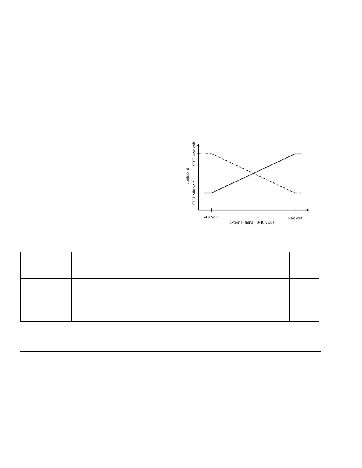
VOLTMAX ELECTRIC BOILER Installation and Operation Manual (Revised August 2017), Page 43.
4.6.3 MODE : DDC 0-10VDC
Modulation of the set-point temperature as a function of 0-10 VDC
(Available only on SCR model)
This operating mode allows to modulate the set-point temperature of
the water outlet of the boiler according to a 0-10VDC signal applied
to the terminal block 0-10Vdc T and 0-10Vdc G from an external
controller (Ex: An energy management software).
A heat demand (closed contact W1 and / or W2-DHW) must be
present so that the boiler can heat up.
Figure 17 : Mode DDC 0-10 VDC
Table 11 : Specific parameters in DDC 0-10 VDC
Display
BACnet variable
Description
Parameters
Default
T. STPT 0-10VDC
AV_TBoilerSTPTCalculatedV
This variable represents the set-point temperature
based on the voltage of the building control system.
0
C or 0F
---
STPT at Min Volt
WP_STPTatMinRemote010V
Set-point of the boiler temperature corresponding to
the voltage level of Min Voltage.
0
C or 0F
80 0F
STPT at Max Volt
WP_STPTatMaxRemote010V
Set-point of the boiler temperature corresponding to
the voltage level of Max Voltage.
0
C or 0F
140 0F
Actual voltage
AV_Remote010VSTPT
Voltage emitted by the external controller in real
time
0-10 V
---
Max Voltage
WP_MinRemoteVSTPT
The maximum voltage that the external controller
can send
0-10 V
10
Min Voltage
WP_MaxRemoteVSTPT
The minimum voltage that the external controller
can send
0-10 V
0
VOLTMAX ELECTRIC BOILER Installation and Operation Manual (Revised August 2017), Page 44.
4.7 W2 MODE SET-POINT TEMPERATURE SETTINGS
Display
BACnet Variable
Description
Selection
Default
Operating Mode
WP_HeatingMod
eW2
Select the boiler’s operating mode during demand on W2 (None, W2
and DHW)
0 = W2
1 = DHW
2 = None
None
4.7.1 W2 MODE
Configures the fixed set-point temperature during demand on W2
Display
BACnet Variable
Description
Selection
Default
W2 Set point
WP_FixedSTPT
W2
Selects the fixed set-point temperature during demand on W2.
10 to 93 0C
50 to 200 0F
175 deg F0
4.7.2 DHW MODE
Configures the fixed set-point temperature during demand on DHW mode.
Display
BACnet Variable
Description
Selection
Default
T. Set-point DHW
WP_FixedSTPT
W2
Selects the fixed set-point temperature during demand on W2
terminale
10 to 93 0C
50 to 200 0F
175 0F
T. Min Boiler
WP_FixedSTPT
W0
Selects the boiler’s minimum temperature.
The boiler’s heating elements will activate automatically to keep the
hydronic system at the selected temperature.
10 to 93 0C
50 to 200 0F
150 0F
4.8 PUMP CONFIGURATION MENU SETTINGS
4.8.1 PUMP 1
Display
BACnet Variable
Description
Selection
Default
Pump
configuration
WP_Pump1Mode
Selects the pump configuration mode (pump contact switch)
0 = None
1 = Always Active
2 = On demand W1
Always
active
Purge delay
WP_Pump1Delay
Configures the pump purge delay (used in W1 On-Demand
mode)
0 to 600 sec
30 sec
4.8.2 PUMP 2
Display
BACnet Variable
Description
Selection
Default
Pump
Configuration
WP_Pump2Mode
Selects the pump configuration mode (pump contact switch)
0 = None
1 = Always Active
2 = On demand W1
3 = Priority on P1
Always
Active
Purge delay
WP_Pump2Delay
Configures the pump purge delay (used in W1 On-Demand
mode)
0 to 600 sec
30 sec

VOLTMAX ELECTRIC BOILER Installation and Operation Manual (Revised August 2017), Page 45.
SPECIFIC PARAMETERS FOR THE CAPACITY LIMITING MENU
The boiler authorizes a maximal power use. The configuration of these modes is shown below.
4.8.3 MANUAL MODE
The maximum power is determined manually
Display
BACnet variable
Description
Parameters
Default
Max capacity
(kW)
Configure the maximum electrical power the boiler will use.
0 to maximum
rated power
---
4.8.4 MODE: 0-10 VDC
(Only available on SCR model)
The modulation of the maximum power is carried out using an external control 0-10 VDC.
Display
BACnet variable
Description
Parameters
Default
Max capacity
(kW)
The calculated power value as a function of the current and the nominal
operating voltage of the boiler
0 to maximum
rated power
---
kW at Min Volt
The maximum permissible power of the boiler when the voltage of the
external controller is at Min Voltage
0 to maximum
rated power
0
kW at Max Volt
The maximum permissible power of the boiler when the voltage of the
external controller is at Min Voltage
0 to maximum
rated power
---
0-10V Current
Signal
Voltage emitted by the external controller in real time
0-10 V
---
Max Voltage
The voltage representing the maximum set-point of the external
controller
0-10 V
10
Min Voltage
The voltage representing the minimum set-point of the external controller
0-10 V
0

VOLTMAX ELECTRIC BOILER Installation and Operation Manual (Revised August 2017), Page 46.
4.9 POWER LIMITATION MENU SETTINGS
You can control the boiler power with different modes. Their configuration is below.
Display
BACnet Variable
Description
Selection
Default
Limitation Mode
WP_CapLimitMo
de
Select the power limitation between
None, Manual, DCC 0-10VDC,T. Ext and Scheduled.
0 = None
1 = Manual
2 = DCC 0-10VDC
3 = T. Ext
4 = Scheduled
---
4.9.1 MANUAL MODE
The maximum power is set manually.
Display
BACnet Variable
Description
Selection
Default
Current
authorized max
kW
WP_ManualCapL
imit
Configures the maximum electrical power that the
boiler will use.
0 to maximum rated power
---
4.9.2 0-10 VDC MODE
(Available on SCR models only)
An external 0-10 VDC controller is used to adjust the maximum power.
Display
BACnet Variable
Description
Selection
Default
Current
authorized max
kW
AV_ActualCapLi
mitkW
The value of power calculated based on the current and the boiler’s
nominal operating voltage
0 to maximum
rated power
(kW)
---
Minimum Power
Volt (kW)
WP_MinRemote
VCapLimit
The boiler’s maximum power when the external controller voltage is at
Min Voltage
0 to maximum
rated power
0
Maximum Power
Volt (kW)
WP_MaxRemote
VCapLimit
The boiler’s maximum power when the external controller voltage is at V
for max. cap.
0 to maximum
rated power
---
Current Signal 010V
AV_Remote010V
Cap
Voltage emitted by the external controller in real time
0-10 V
---
Min Voltage
(VDC)
WP_CapLimitatM
inRemote010V
The voltage representing the external controller’s minimum set-point
0-10 V
0
Max Voltage
(VDC)
WP_CapLimitatM
axRemote010V
The voltage representing the external controller’s maximum set-point
0-10 V
10

VOLTMAX ELECTRIC BOILER Installation and Operation Manual (Revised August 2017), Page 47.
4.9.3 T. EXT MODE
Maximum power modulation is based on the outside
temperature. Power modulation is shown below.
If the external sensor is not connected or there is a problem with
the sensor, then the power will be limited according to Cap. At T.
Ext. Min.
Figure 18: Adjustment curve according to the T. ext mode
Display
BACnet Variable
Description
Parameters
Default
Max capacity
(kW)
AV_ActualCapLi
mitkW
The value of power calculated based on the current and the boiler’s
nominal operating voltage
0 to maximum rated
power
---
Cap. At T. Ext.
Min
WP_CapLimitatM
inOutdT
Maximum authorized capacity according to T. Ext. Min
Ex. Maximum power is 170 kW for T. Ext min
0 to maximum rated
power
---
Cap. At T. Ext.
Max
WP_CapLimitatM
axOutdT
Maximum authorized capacity according to T. Ext. Max
Ex. Maximum power is 120 kW for T. Ext min
0 to maximum rated
power
---
Actual T. Exterior
AV_OutdoorT
This variable allows you to view the outside temperature in real time
when the outside temperature sensor is properly connected.
-46 to 107 °C
-50 to 250 °F
---
T. Ext. Min
WP_MinOutdTCa
pLimit
Minimal outside temperature used to adjust the maximum power
-46 to 107 °C
-50 to 250 °F
-10 F
T. Ext. Max
WP_MaxOutdTC
apLimit
Maximum outside temperature used to adjust the maximum power
-46 to 107 °C
-50 to 250 °F
65 F

VOLTMAX ELECTRIC BOILER Installation and Operation Manual (Revised August 2017), Page 48.
4.9.4 SCHEDULE MODE
Power can be modulated according to a fixed schedule. This can be programmed in the Schedule Setting menu.
Display
BACnet variable
Description
Parameters
Default
Max capacity
(kW)
AV_ActualCapLi
mitkW
Maximum capacity allowed at present time.
0 to maximum rated
power
---
Cap In Schedule
WP_CapLimitDay
Mode
Power limitation when the boiler internal clock is within the power
limitation schedule.
0 to maximum rated
power
---
Cap Out
Schedule
WP_CapLimitNig
htMode
Power limitation when the boiler internal clock is outside the power
limitation schedule.
0 to maximum rated
power
---
Schedule
---
Configuring the boiler power limitation schedule. In order to operate
correctly, you must first adjust the internal boiler clock in the Clock
Setting menu.
---
---

VOLTMAX ELECTRIC BOILER Installation and Operation Manual (Revised August 2017), Page 49.
4.10 AUXILIARY BOILER SETTINGS
(Only available on SCR model)
The system allows control of an auxiliary boiler to the system. The different configuration options are shown below.
In order for the boiler to start, two conditions must be met:
The water outlet temperature of the Voltmax boiler must be below the start-up
temperature Aux.
(T. Out Boiler < (T Set-point - Delta T. Aux Start)
The water outlet temperature of the Voltmax boiler must be below the start-up
temperature Aux. for a period of X minutes (Start Delay Aux), after the Voltmax
boiler is at 100% of its authorized power.
In order for the auxiliary boiler to turn off, the water outlet temperature of the
Voltmax boiler must be above the Aux.
T Out Boiler > (T. Set-point - Delta T. Aux Stop)
4.10.1 BACKUP MODE
Configures a second boiler as a backup.
Display
BACnet variable
Description
Parameters
Default
STPT Source
WP_STPTSource
Aux
Selects the source used to control the set-point temperature.
Auxiliary means that the set-point will be determined by the auxiliary
boiler. The VOLTMAX boiler therefore has no set-point temperature and
is only used to activate the auxiliary boiler relay.
Voltmax means that the set-point temperature will be determined by the
VOLTMAX boiler.
Auxiliary or
VOLTMAX
0 = Auxilliary
1 = VOLTMAX
VOLTMAX
Delta T. Start
Aux.
WP_DeltaTStartA
ux
This option adjusts the temperature differential (set-point temperature –
Water outlet temperature) used to activate the auxiliary boiler.
0 to 55 0C
0 to 100 0F
20 0F
Delta T. Stop
Aux.
WP_DeltaTStopA
ux
This option configures the temperature differential (set-point temperature
– Water outlet temperature) in the VOLTMAX boiler used to deactivate
the auxiliary boiler.
0 to 55 0C
0 to 100 0F
5 0F
Delay Start Aux.
WP_DelayStartA
ux
This option adjusts the delay in minutes before activating the auxiliary
boiler.
Min
10

VOLTMAX ELECTRIC BOILER Installation and Operation Manual (Revised August 2017), Page 50.
4.10.2 EXTERNAL CONTACT MODE
This mode selects the hydronic system heating source (VOLTMAX boiler or auxiliary boiler) using the BI-E terminal’s electrical switch.
Display
BACnet
Variable
Description
Settings
Default
STPT Source
WP_STPTSourc
eAux
Selects the source used to control the set-point temperature.
External means that the set-point will be determined by the auxiliary
boiler. The VOLTMAX boiler therefore has no set-point temperature and is
used only to activate the auxiliary boiler’s relay.
Internal means that the set-point temperature will be determined by the
VOLTMAX boiler.
External or
internal
Internal
4.10.3 MANUAL MODE
Manual mode is used to select the system’s operating mode (Electric or auxiliary).
Display
BACnet Variable
Description
Selection
Default
Active Boiler
WP_ActiveBoiler
This option selects which boiler is in operation; either the VOLTMAX
boiler (electric) or the auxiliary boilder (auxiliary).
VOLTMAX ou
Auxiliary
0 = VOLTMAX
1 = Auxiliary
VOLTMAX
4.10.4 BI-ENERGY MODE
This mode selects the hydronic system heating source (VOLTMAX boiler or auxiliary boiler) using the BI-E terminal’s electrical switch. The benefit of this
mode is that the system can operate the back-up boiler when needed.
Display
BACnet variable
Description
Parameters
Default
STPT Source
WP_STPTSource
Aux
Selects the source used to control the set-point temperature.
Auxiliary means that the set-point will be determined by the auxiliary
boiler. The VOLTMAX boiler has no set-point temperature and is only
used to activate the auxiliary boiler relay.
Voltmax means that the set-point temperature will be determined by the
VOLTMAX boiler.
Auxiliary or
VOLTMAX
0 = Auxiliary
1 = VOLTMAX
VOLTMAX
Delta T. Start
Aux.
WP_DeltaTStartA
ux
This option adjusts the temperature differential (Set-point temperature –
Water outlet temperature) used to activate the auxiliary boiler.
0 to 55 0C
0 to 100 0F
20 0F
Delta T. Stop
Aux.
WP_DeltaTStopA
ux
This option configures the temperature differential (Set-point temperature
– Water outlet temperature) in the VOLTMAX boiler used to deactivate
the auxiliary boiler.
0 to 55 0C
0 to 100 0F
5 0F
Delay Start Aux.
WP_DelayStartA
ux
This option adjusts the delay in minutes before activating the auxiliary
boiler.
Min
10

VOLTMAX ELECTRIC BOILER Installation and Operation Manual (Revised August 2017), Page 51.
4.11 LIMIT CONFIGURATION MENU SETTINGS
Display
BACnet variable
Description
Settings
Default
Haute Limite T
WP_HighLimitTemp
Adjusts the temperature high limit at which the alarm
triggers. If the water temperature leaving the boiler
exceeds the alarm’s high limit, it will trigger an HL
alarm and the boiler’s heating elements will be
deactivated.
0 to 92 °C
0 to 199 °F
180 °F
Delta T. LL
WP_DeltaTLL
Adjusts the temperature differential to activate the LL
alarm.
0 to -55 °C
0 to -99 °F
-20 °F
Delay LL (min)
WP_DelayLL
Adjusts the LL alarm trigger delay .
0 to 180 min
60 min
Pressure sensor
WP_ActivatePressureSensor
Activates the boiler’s internal pressure sensor module.
OFF / ON
0 = Off ; 1 = On
ON
Actual pressure
AV_SensorPressureSignal
Reads the boiler’s internal pressure sensor.
---
---
Current sensor
WP_ActivateCurrentSensor
Activates the current sensor module.
This module is available on SCR models only
OFF / ON
0 = Off ; 1 = On
ON
Calculated
current
AV_CalculatedCurrentSignal
Used to view the VOLTMAX boiler’s theoretical
electric consumption current.
---
---
Actual current
AV_SensorCurrentSignal
View current as measured by a sensor.
---
---

VOLTMAX ELECTRIC BOILER Installation and Operation Manual (Revised August 2017), Page 52.
4.12 CONFIG. ALARM MENU SETTINGS
Display
BACnet Variable
Description
Possible Settings
Default
Status:
HL/LWCO alarm
BV_StatusExtAlarm
Displays the external alarm status. The external
alarm contact is activated only if a high limit or low
water level alarm occurs.
0 = Off
1 = On
---
Silence Alarm
WP_SilenceAlarm
Temporarily suspends the alarm .
0 = Off
1 = On
Off
Reset Lockdown
WP_ResetLockDown
Cancels the Lockdown mode without resetting the
unit.
Resetting the unit is required when it is in LOCK-OUT
mode, following repeated alarms over a short period.
0 = Off
1 = On
Off
Internal buzzer
WP_ActivateInternalBuzzer
Activates the controller’s internal buzzer.
0 = Off
1 = On
On
Deactivate LL
alarm
WP_DeactivateAlarmLL ()
Deactivates the LL alarm.
0 = Off 1 = On
Off
4.13 OCCUPATION MENU SETTINGS
Display
BACnet Variable
Description
Possible Settings
Default
Occupation
Mode
WP_ActivateOccupationMode
Activates the Occupation function.
0 = Off
1 = On
---
Source OCC
WP_SourceOccupation
Selects the source used to determine the building’s
occupation schedule.
0 = Schedule
1 = Contact OCC
Lowering T.
WP_LoweringTInnoccupation
Lowers the set-point temperature.
---
Off
Occupation
Status
BV_StatusOccupation
Displays the Occupation mode status.
Off: Day mode; the set-point temperature is not
lowered
On: Night mode; the set-point temperature is lowered
according to the configuration
0 = Off
1 = On
On
Force Day Mode
WP_ForceOccupationDay
Forces the Day mode. The set-point temperature will
not be lowered.
0 = Off ; 1 = On
Off

VOLTMAX ELECTRIC BOILER Installation and Operation Manual (Revised August 2017), Page 53.
4.14 BOOST MENU SETTINGS
Display
BACnet Variable
Description
Possible Settings
Default
Mode BOOST
WP_ActivateModeBoost
This option enables the BOOST functionality.
0 = Off
1 = On
Off
4.15 WARM WEATHER SHUTDOWN MENU SETTINGS
Display
BACnet Variable
Description
Possible Settings
Default
Warm Weather
Shutdown
WP_ActivateWarmWeatherSD
Shuts down the boiler when the outside temperature
reaches a specific temperature. This temperature can
be set in the Warm Weather Shutdown Temperature
box.
OFF / ON
0 = Off ; 1 = On
OFF
T. Ext Shutdown
WWSD
WP_WarmWeatherSDTemp
Sets the outside temperature that activates the Warm
Weather Shutdown, if it shuts down the boiler.
0 to 55 °C
0 to 99 °F
68 °F
Current Ext. T.
AV_OutdoorT
Shows the outside temperature in real time.
-46 to 107 °C
-50 to 250 °F
---

WARNING
!
SECTION 5 : BOILER START UP
Before operating this boiler, be sure to read and follow these instructions, as well as the
warnings printed in this manual. Failure to do so can result in unsafe operation of the
boiler resulting in property damage, bodily injury, or death. Should you have any problems
reading, following or difficulty in understanding the instructions in this manual, STOP, and
get help from a qualified person.
Do not turn on the boiler unless it is filled with water. Do not turn on the boiler if the cold-water
supply shut-off valve is closed.
After the boiler, has been plumbed and wired, it
is now ready to be set for automatic operation
5.1 FILLING THE BOILER
Open the service valves at the outlet of the
boiler and the cold-water supply valve (fill or
makeup water valve) to boiler.
Open the relief valve on top of the boiler in order
to purge the air out of the boiler tank during the
fill process
Leave all shutoff valves open.
Check system for leaks and repair. Purge air
from all the heating distribution zones.
Bleed air from different areas of the heat
distribution system.
Check boiler pressure gage reading. The
indicated pressure should be lower than the
pressure relief valve design rating.
5.2 ADJUSTEMENT OF THE
CONTROLLER OPERATING
PARAMETERS
After the system has been manually purged of
air, and all components (valves, vents,
controllers) have been set properly, the boiler
can be started.
Never operate this boiler until this has been
done.
Consider safety and energy-savings when
adjusting the boiler’s water temperature. It is
more energy-efficient to maintain a set-point as
low as possible while still meeting heating
needs.
Safety and energy conservation are factors to be
considered when setting the boiler water
operating temperature. The most energyefficient operation will result when the
temperature setting of the controller is the lowest
that satisfies the heating needs.
Make sure that the input of the operating
parameters of the controller as well as the
adjustable high mechanical limit control of the
boiler corresponding to the values required for
the application.
Adjusting the high limit is possible in the Limit
Setting menu. The High temperature limit
should be adjusted from 15 to 20F higher than
the maximum operating temperature.
5.3 STARTUP PROCEDURE
Before starting the boiler, make sure that the
heating distribution design is made so that the
heating elements will come on only when water
is circulating in the boiler.
1) Fill the boiler as described in Section 5.1.
2) Set the boiler operating temperature as
described in Section 4.
3) Cancel all heating demand from the
distribution system.
4) Turn on the boiler power breakers
and switch.
5) The main contactors should be activated in
sequence and the controller display shall be
lighted. The heating elements shall not
come on because there is no heat demand
applied to the controller and if there is no
water circulation in the unit.
6) Apply a heat demand. If the boiler target
temperature is higher than the boiler water
temperature, the heating elements shall
come on in sequence more or less rapidly
depending on the differential between the
values.
N.B. It is normal that the elements be activated
very rapidly during the boiler start-up since this
temperature differential is generally high at this
moment.
VOLTMAX ELECTRIC BOILER Installation and Operation Manual (Revised August 2017), Page 54.

7) When the boiler capacity has reached 100%
as displayed on the controller, measure the
amperage and voltage values drawn by the
unit. These values shall be close to those
shown on the boiler name plate.
8) Slow down the heat demand from the heating
system. The boiler temperature shall
gradually increase and the boiler capacity
shall drop gradually and stabilize when the
boiler temperature will reach a temperature
near the target temperature.
9) When the heating request is completed, the
circulating pump can continue to operate
(depending on the operating mode or the
purge time) or switch off. The heating
elements stop working.
10) Check the operation of the adjustable highlimit mechanical control.
11) Check the operation of the Low Water Cut
OFF by pressing its test button during 5 sec.
VOLTMAX ELECTRIC BOILER Installation and Operation Manual (Revised August 2017), Page 55.

Active
warning
light
Boiler status
Green
Normal operation of the boiler
Yellow
One or more alarms are active.
These alarms do not prevent the
operation of the boiler; the boiler
continues to operate in normal
mode.
Ex. The controller detects a problem
with the amperage reading sensor.
Red
A critical alarm is active,
accompanied by the buzzer (if
active).
Ex. A high limit alarm is active
SECTION 6 : TROUBLESHOOTING
The troubleshooting section shows the various
error messages that can occur during abnormal
operation of the boiler.
It is possible to change the limits of some alarms
on the controller in the Limit Setting.
6.1 WARNING LIGHTS
The LEDs above the navigation buttons indicate
3 different boiler states.
6.2 OPERATING PROBLEM
IDENTIFICATION
An alarm log is available in the BOILER
CONFIG / ALARM / ALARM LOG. Each alarm
is recorded with its alarm code, the time and
date. The register can record up to 30 alarms.
6.2.1 EXTERNAL HL / LWCO
When this alarm is present, the indicator light to
the left of the boiler lights red.
This alarm happens when one of the two
external sensors (External fault Low Water Cut
Off or External High limit) is triggered.
Look for the cause of this contact opening which
normally occurs when there is a lack of water in
the boiler according to the low water level
sensor (Standard on 120 kW models and higher)
or when the high temperature limit control
detects a temperature higher than 210°F.
VOLTMAX ELECTRIC BOILER Installation and Operation Manual (Revised August 2017), Page 56.
The external alarm contact will be activated
immediately if it has been activated (Ext. Alarm
Contact) in the Alarm menu. The heating
elements stop working and will start again when
the water level returns to normal. If this alarm
happens 3 times in 1 hour, the boiler will be set
in Lock out mode.
6.2.2 SENSOR ( SE )
The Sensor alarm is activated when the
controller detects a problem with a sensor.
This alarm usually appears with another alarm,
for example the flow rate alarm (F) and the
sensor alarm (SE), this help target a flow sensor
problem, for example.
See Table 13 for comparison of Resistance
measurements against temperature for the
outdoor sensor.
6.2.3 LOW LIMIT ( LL )
The LL alarm is activated when the temperature
differential between the set-point temperature
and the boiler output temperature is higher than
Delta T.LL and this period is higher than the LL
delay.
The heating elements remain in operation. The
screen will automatically return to its normal
state. When the temperature of the boiler
approaches the set temperature.
6.2.4 FLOW ( F )
(Available only on SCR model)
The flow alarm is triggered when the theoretical
flow calculation is below the manufacturer's
authorized flow limit.
6.2.5 CURRENT ( A )
(Available only on SCR model)
The Current alarm is triggered when there is a
difference of more than 20% between the
measured current (Available only on SCR

Temperature
Resistance
Temperature
Resistance
Temperature
Resistance
Temperature
Resistance
°F
°C Ω °F
°C Ω °F
°C Ω °F
°C
Ω
-50
-46
490 813
20
-7
46 218
90
32
7 334
160
71
1 689
-45
-43
405 710
25
-4
39 913
95
35
6 532
165
74
1 538
-40
-40
336 606
30
-1
34 558
100
38
5 828
170
77
1 403
-35
-37
280 279
35 2 29 996
105
41
5 210
175
79
1 281
-30
-34
234 196
40 4 26 099
110
43
4 665
180
82
1 172
-25
-32
196 358
45 7 22 763
115
46
4 184
185
85
1 073
-20
-29
165 180
50
10
19 900
120
49
3 760
190
88
983
-15
-26
139 402
55
13
17 436
125
52
3 383
195
91
903
-10
-23
118 018
60
16
15 311
130
54
3 050
200
93
829
-5
-21
100 221
65
18
13 474
135
57
2 754
205
96
763
0
-18
85 362
70
21
11 883
140
60
2 490
210
99
703
5
-15
72 918
75
24
10 501
145
63
2 255
215
102
648
10
-12
62 465
80
27
9 299
150
66
2 045
220
104
598
15
-9
53 658
85
29
8 250
155
68
1 857
225
107
553
model) and the calculated theoretical current.
This may indicate an electrical problem from a
wrong connection.
limit (depending on the maximum boiler
pressure)
6.2.9 LOCK OUT
6.2.6 HL TEMPERATURE ( HL )
The outlet temperature of the boiler is above the
high limit allowed. This alarm triggers the
deactivation of the heating elements of the
boiler.
The boiler is restarted when the temperature
drops below the high limit (and the set-point)
If the boiler is in this alarm state for more than
25 minutes, the boiler switches to Lock Out
mode.
6.2.7 LOW PRESSURE ( P )
The Low Pressure alarm is activated when the
pressure inside the boiler is below the allowed
limit (default: 5 psi).
6.2.8 HIGH PRESSURE ( P )
The High Pressure alarm is activated when the
pressure inside the boiler is above the allowed
Lock out mode is activated after 3 major alarms
have been activated within one hour. When the
lock mode is activated, the boiler is deactivated
and can only be restarted by restarting the boiler
(to the left of the control panel) or by using the
reset Lock Out function (in the alarm setting
menu).
Tableau 12 : Resistance (Ohm) according to the outdoor sensor measuring temperature
VOLTMAX ELECTRIC BOILER Installation and Operation Manual (Revised August 2017), Page 57.

DANGER
!
WARNING
!
SECTION 7 : MAINTENANCE
Properly maintained, your boiler will provide years of dependable, trouble free service. It is recommended that
a regular routine maintenance program be established and followed by the user. Components are subject to
eventual failure that requires service. Failure to use the correct procedures or parts in these circumstances
may make the unit unsafe or reduce the life of the boiler.
The owner should have the following inspection and maintenance procedures performed:
7.1 BOILER WATER PIPING
YEARLY VISUAL INSPECTION
Check all piping for signs of leakage near joints,
unions and shut-off valves. Repair as needed.
7.2 PRESSURE RELIEF VALVE
TWICE A YEAR
Check for possible leak at the outlet of the safety
relief valve. If a leak is detected and the pressure
at the indicator is less than 28psi, change the
safety relief valve with a new one having similar
characteristics. If the pressure is higher than 28psi,
ask your heating service agency to determine the
cause of the high pressure and have it corrected
rapidly. Do not plug the outlet of this valve if a
dripping condition occurs.
7.3 AIR PURGE
TWICE A YEAR
Check for proper operation of the automatic air
purgers and activate manual air vents to eliminate
air present.
7.4 ELECTRICAL INSPECTION
ANNUALLY
It is recommended to perform a visual inspection of
the boiler electric compartment annually, during the
heating season, to ensure it is watertight and that
there are no signs of component or wiring
overheating. Repair as soon as possible if
necessary. Defective components should always
be replaced with the Original Manufacturer’s parts.
The inspection should also include a check of the
main temperature controls in operation as well as
an amperage reading to verify the proper operation
of all the heating elements.
The manufacturer's warranty DOES NOT cover
a tank breakage caused by improper
installation or maintenance. If the boiler safety
valve opens periodically, this may be caused
by the expansion tank.
Immediately call a qualified technician to
inspect and remedy the problem.
NOTE: To prevent premature tank failure, the
air trapped inside the tank must be purged
periodically.
Before manually operating the relief valve,
make certain no one will be sprayed with the
hot water released by its opening. The water
may be hot enough to create a SCALD hazard.
The water released should be directed to a
suitable drain to prevent injury or damage.
VOLTMAX ELECTRIC BOILER Installation and Operation Manual (Revised August 2017), Page 58.

THERMO 2OOO INC.
500, 9
ième
Avenue, Richmond (Qc) Canada J0B 2H0
Tel: (819) 826-5613 Fax: (819) 826-6370
www.thermo2000.com
VOLTMAX LIMITED WARRANTY
Warranty Coverage for Commercial Installation
Thermo 2000 Inc. warrants to the original purchaser that the DTHUltra
tank installed in a commercial setting for ten (10) years.
Commercial setting shall mean use in other than residential setting stated
above in the residential setting definition. In the event that a leak should
develop and occur within this limited warranty period due to defective
material or workmanship, such leak having been verified by an authorized
company representative, Thermo 2000 Inc. will repair or replace at our
sole option the failed unit with the nearest comparable model at the time of
replacement.
The original purchaser is responsible for all costs associated with the
removal and reinstallation, shipping and handling to and from
Manufacturer. The replacement unit will be warranted for the remaining
portion of the original Warranty.
Limited two-year warranty on all VOLTMAX
components & parts
All other DTHUltra components & parts are warranted for a period of two
(2) years against defects due to defective material or workmanship. The
original purchaser is responsible for all costs associated with the removal
and reinstallation, shipping and handling to and from Manufacturer. The
components, repaired or replaced are warranted for the residual period of
the initial warranty on the unit.
Limitations
Thermo 2000 shall not be responsible for any damage, loss, and
inconvenience of any nature whatsoever, directly or indirectly, relating to
the breakdown or malfunction of the unit. This warranty limits its
beneficiary’s rights. Nevertheless, the beneficiary may have other rights,
which vary from state to state.
This warranty replaces any other expressed or implicit warranty and
constitutes the sole obligation of Thermo 2000 towards the consumer. The
warranty does not cover cost of removal, reinstallation or shipping to repair
or replace the unit, nor administration fees incurred by the original
consumer purchaser.
Thermo 2000 reserves its rights to make changes in the details of design,
construction, or material, as shall in its judgment constitute an
improvement of former practices.
This warranty is valid only for installations made within the territorial limits
of Canada and the United States.
Warranty service procedure
Only authorized VOLTMAX retailers may handle warranty claims. The
owner or contractor must provide the defective equipment to Thermo 2000
with the following details: the model, the serial number, a copy of the
original invoice and the owner identification certificate.
Exclusions
This warranty is void and shall not apply if:
A) Defects or malfunctions resulting from installation, repair,
maintenance and/or usage that are not done in conformity with the
manufacturer’s installation manual; or
B) Defects or malfunctions resulting from installation, maintenance, or
repair that are not done in accordance with regulations in force; or
C) Defects or malfunctions resulting from improper installation,
maintenance or repair done carelessly or resulting from consumer
damage (improper maintenance, misuse, abuse, accident or
alteration); or
D) Installation in which a relief valve (pressure) is not installed or if it is
not functioning properly, or when it is not connected to a drain to
avoid damage to the property; or
E) Installation in which liquid circulating in the tank does not remain in
closed circuit or installation in which piping is leaking; or
F) A polybutylene pipe or radiant panel installation without an oxygen
absorption barrier is used; or
G) Installation where the acidity of water is not within the normal
Environmental Protection Agency (EPA) (between pH 6.5 – 8.5)
guidelines or the water contains abnormal levels of particulate
matter or water exceeding 10.5 gpg; or
H) Your home contains any type of water softener system and the unit
is not installed and maintained in accordance with the manufacturer
specifications; or
I) The DTH Ultra unit is being subject to non-authorized modifications;
or
J) Defects or malfunction resulting of storing or handling done
elsewhere than Thermo 2000’s manufacturing plant; or
K) Units on which the serial number is removed or obliterated.
VOLTMAX ELECTRIC BOILER Installation and Operation Manual (Revised August 2017), Page 59.
 Loading...