

THERMO 2000 VoltMax80, VoltMax96, VoltMax84, VoltMax77, VoltMax105 Installation And Operation Manual
...
1
VoltMax 400
Electric Boiler
INSTALLATION AND OPERATION MANUAL
Your VoltMax Electric Boiler was carefully assembled and checked at the factory to ensure its proper
functioning for many years. The following information and safety measures are provided to enable proper
installation, operation, and maintenance of this product.
It is imperative that all persons who are expected to install, operate or adjust this boiler should read these
instructions carefully.
Any questions regarding the operation, maintenance, service or warranty of this electric boiler should be
directed to the installer or to a skilled technician.
When all installation steps have been completed, keep this installation manual in a safe place (near the
boiler) for future reference.
THERMO 2000 INC.
Printed in Canada Revised: march 2019
VOLTMAX ELECTRIC BOILER Installation and Operation Manual (Revised March 2019), Page 2.
TABLE OF CONTENTS
TECHNICAL SPECIFICATIONS .............................................................................................. 4
INTRODUCTION ....................................................................................................................... 8
LOCAL INSTALLATION REGULATIONS ............................................................................................. 8
CORROSIVE ENVIRONMENT ............................................................................................................ 8
INSPECTION UPON RECEPTION ...................................................................................................... 8
TO BE CHECKED ................................................................................................................................ 8
INSTALLATION ........................................................................................................................ 9
SAFETY MEASURES .......................................................................................................................... 9
LOCATION ........................................................................................................................................... 9
CLEARANCES ..................................................................................................................................... 9
PIPING INSTALLATION ....................................................................................................................... 9
Boiler piping connection ...................................................................................................... 10
Auxiliary boiler piping connection ........................................................................................ 10
Safety valve ........................................................................................................................ 10
System pressure control and expansion tank ..................................................................... 11
Water pressure makeup regulator ....................................................................................... 11
Air bleeder .......................................................................................................................... 11
Circulating pump ................................................................................................................. 11
Drain faucet......................................................................................................................... 12
Sieve ................................................................................................ ................................... 12
Pressure loss ...................................................................................................................... 13
ELECTRICAL CONNECTIONS .......................................................................................................... 19
Main electrical supply .......................................................................................................... 19
Pump supply ................................ ....................................................................................... 19
Connection of external signals to the controller .................................................................. 19
CONTROLLER OPERATION ................................................................................................. 23
USER INTERFACE ............................................................................................................................ 23
Symbol description .............................................................................................................. 23
Control panel....................................................................................................................... 24
Navigation and adjustements .............................................................................................. 24
Main menu navigation ................................................................ ................................ ......... 25
Navigation in boiler setting .................................................................................................. 26
MAIN MENU ....................................................................................................................................... 29
Boiler status ........................................................................................................................ 29
Boiler configuration ............................................................................................................. 29
User setting ......................................................................................................................... 29
Clock setting ....................................................................................................................... 30
Consumption ....................................................................................................................... 30
BOILER SETTINGS ........................................................................................................................... 30
Heating mode W1 ............................................................................................................... 31
Heating mode W2/DHW ...................................................................................................... 32
Capacity limiting .................................................................................................................. 32
Auxiliary boiler..................................................................................................................... 33
Limit setting ......................................................................................................................... 34
Alarm .................................................................................................................................. 34
Communication ................................................................................................................... 34
Config. BACnet ................................................................................................................... 35
Occupation .......................................................................................................................... 36
BOOST Mode ..................................................................................................................... 37
Warm weather shutdown .................................................................................................... 37
Change password ............................................................................................................... 37
ETHERNET ........................................................................................................................................ 37
Web PORTAL ..................................................................................................................... 37
Alarm notification Email ...................................................................................................... 37
BOILER STATUS DISPLAY SETTINGS ............................................................................................ 39
HEATING MODE W1 SETTINGS ...................................................................................................... 41
FIXED MODE...................................................................................................................... 41
OUTDOOR RESET MODE ................................................................................................. 42
MODE: DDC 0-10VDC ........................................................................................................ 43
W2 MODE SET-POINT TEMPERATURE SETTINGS ....................................................................... 44
VOLTMAX ELECTRIC BOILER Installation and Operation Manual (Revised March 2019), Page 3.
W2 MODE ........................................................................................................................... 44
DHW MODE........................................................................................................................ 44
POWER LIMITATION MENU SETTINGS .......................................................................................... 44
MANUAL MODE ................................................................................................................. 45
0-10 VDC MODE ................................................................................................................ 45
T. ext MODE ....................................................................................................................... 46
Schedule MODE ................................................................................................................. 47
AUXILIARY BOILER SETTINGS ........................................................................................................ 47
BACKUP MODE ................................................................................................................. 48
EXTERNAL CONTACT MODE ........................................................................................... 48
ManuAl MODE .................................................................................................................... 48
Bi-Energy MODE ................................................................................................................ 49
LIMIT CONFIGURATION MENU SETTINGS ................................................................................... 50
CONFIG. ALARM MENU SETTINGS ............................................................................................... 51
OCCUPATION MENU SETTINGS ................................................................................................... 51
BOOST MENU SETTINGS .............................................................................................................. 52
WARM WEATHER SHUTDOWN MENU SETTINGS ....................................................................... 52
BOILER START UP ................................................................................................................ 53
STARTUP PREPARATION ................................................................................................................ 53
ADJUSTEMENT OF THE CONTROLLER OPERATING PARAMETERS .......................................... 53
STARTUP PROCEDURE ................................................................................................................... 54
TROUBLESHOOTING ............................................................................................................ 55
WARNING LIGHTS ............................................................................................................................ 55
OPERATING PROBLEM IDENTIFICATION ...................................................................................... 55
External HL / LWCO ........................................................................................................... 55
Sensor (SE) ........................................................................................................................ 55
Low limit (LL)....................................................................................................................... 55
Flow (F) ............................................................................................................................... 56
Current (A) .......................................................................................................................... 56
HL temperature (HL) ........................................................................................................... 56
Low pressure (P) ................................................................................................................. 56
High pressure (P) ................................................................................................................ 56
Battery low level ................................................................................................................. 56
Lock out ............................................................................................................................. 56
FUSES ............................................................................................................................................... 58
CONTACTOR ..................................................................................................................................... 58
HEATING ELEMENTS ....................................................................................................................... 58
TEMPERATURE SENSOR ................................................................................................................ 58
EXTERNAL HIGH LIMIT CONTROL .................................................................................................. 58
INTERNAL CLOCK ............................................................................................................................ 58
MAINTENANce....................................................................................................................... 59
BOILER WATER PIPING ................................................................ ................................................... 59
PRESSURE RELIEF VALVE .............................................................................................................. 59
AIR PURGE ........................................................................................................................................ 59
ELECTRICAL INSPECTION .............................................................................................................. 59
VOLTMAX ELECTRIC BOILER Installation and Operation Manual (Revised March 2019), Page 4.
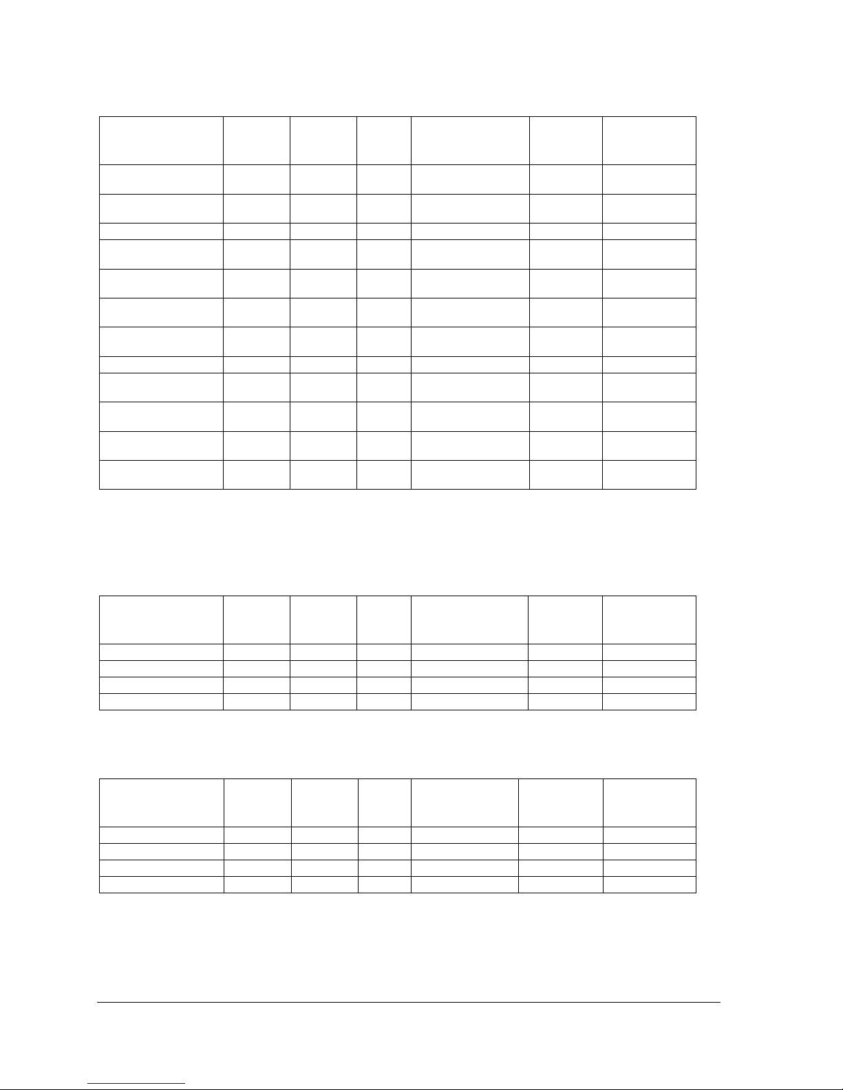
TECHNICAL SPECIFICATIONS
Table 1 : VoltMax 600 VAC / 60 Hz / 3 Phases
1
Model
BTU/h
kW
Amps
Elements 600V
Stage
2
max. power
supply
(MCM)3
VoltMax 192
655 104
192
185
8 x 15 kW
4 x 18 kW
4 x 48 kW
3 x 350
VoltMax 204
696 048
204
197
8 x 18 kW
4 x 15 kW
4 x 51 kW
3 x 350
VoltMax 216
736 996
216
208
12 x 18 kW
4 x 54 kW
3 x 350
VoltMax 225
767 700
225
217
15 x 15 kW
5 x 45 kW
3 x 350
VoltMax 240
818 880
240
231
10 x 15 kW
5 x 18 kW
5 x 48 kW
3 x 350
VoltMax 255
870 060
255
246
10 x 18 kW
5 x 15 kW
5 x 51 kW
3 x 350
VoltMax 270
921 240
270
260
15 x 18 kW
5 x 54 kW
3 x 500
VoltMax 288
982 656
288
277
12 x 15 kW
6 x 18 kW
6 x 48 kW
3 x 500
VoltMax 306
1 044 072
306
295
12 x 18 kW
6 x 15 kW
6 x 51 kW
3 x 500
VoltMax 315
1 074 780
315
303
21 x 15 kW
7 x 45 kW
3 x 500
VoltMax 324
1 105 488
324
312
18 x 18 kW
6 x 54 kW
3 x 500
VoltMax 336
1 146 432
336
324
14 x 15 kW
7 x 18 kW
7 x 48 kW
3 x 600
VoltMax 357
1 218 084
357
344
14 x 18 kW
7 x 15 kW
7 x 51 kW
3 x 600
VoltMax 378
1 289 736
378
364
21 x 18 kW
7 x 54 kW
6 x 300
VoltMax 384
1 310 208
384
370
16 x 15 kW
8 x 18 kW
8 x 48 kW
6 x 300
VoltMax 408
1 392 096
408
393
16 x 18 kW
8 x 15 kW
8 x 51 kW
6 x 300
1
Electrical supply 600 V 3 phase (L1-L2-L3) with 3 conductors Cu or AL ,90 °C with a ground.
2
The 45 kW stage is composed of three 15 kW elements.
The 48 kW stage is composed of two 15 kW elements and one 18 kW element.
The 51 kW stage is composed of one 15 kW element and two 18 kW elements.
The 54 kW stage is composed of three 18 kW elements.
3
-Maximum capacity of the boilers connection terminals
VOLTMAX ELECTRIC BOILER Installation and Operation Manual (Revised March 2019), Page 5.
Table 2 : VoltMax 480 VAC / 60 Hz / 3 Phases
1
Model
BTU/h
kW
Amps
Elements 480V
Stage
2
max. power
supply
(MCM)3
VoltMax 192
655 104
192
231
8 x 15 kW
4 x 18 kW
4 x 48 kW
3 x 350
VoltMax 204
696 048
204
246
8 x 18 kW
4 x 15 kW
4 x 51 kW
3 x 500
VoltMax 225
767 700
225
271
15 x 15 kW
5 x 45 kW
3 x 500
VoltMax 240
818 880
240
289
10 x 15 kW
5 x 18 kW
5 x 48 kW
3 x 500
VoltMax 255
870 060
255
307
10 x 18 kW
5 x 15 kW
5 x 51 kW
3 x 500
VoltMax 288
982 656
288
347
12 x 15 kW
6 x 18 kW
6 x 48 kW
3 x600
VoltMax 306
1 044 072
306
368
12 x 18 kW
6 x 15 kW
6 x 51 kW
3 x600
VoltMax 315
1 074 780
315
379
21 x 15 kW
7 x 45 kW
6 x 300
VoltMax 336
1 146 432
336
405
14 x 15 kW
7 x 18 kW
7 x 48 kW
6 x 300
VoltMax 357
1 218 084
357
430
14 x 18 kW
7 x 15 kW
7 x 51 kW
6 x 300
VoltMax 384
1 310 208
384
462
16 x 15 kW
8 x 18 kW
8 x 48 kW
6 x 300
VoltMax 408
1 392 096
408
491
16 x 18 kW
8 x 15 kW
8 x 51 kW
6 x 500
1
Electrical supply 480 V 3 phase (L1-L2-L3) with 3 conductors Cu or AL ,90 °C with a ground.
2
The 45 kW stage is composed of three 15 kW elements.
The 48 kW stage is composed of two 15 kW elements and one 18 kW element.
The 51 kW stage is composed of one 15 kW element and two 18 kW elements.
3
-Maximum capacity of the boilers connection terminals
Table 3 : VoltMax 240 VAC / 60 Hz / 3 Phases
1
Model
BTU/h
kW
Amps
Elements 240V
Stage
max. power
supply
(MCM)2
VoltMax 105
358 260
105
253
7 x 15 kW
7 x 15 kW
3 x 500
VoltMax 120
409 440
120
289
8 x 15 kW
8 x 15 kW
3 x 500
VoltMax 126
429 912
126
303
7 X 18 kW
7 X 18 kW
3 x 500
VoltMax 144
491 328
144
347
8 x 18 kW
8 x 18 kW
3 x 500
1
Electrical supply 240 V 3 phase (L1-L2-L3) with 3 conductors Cu or AL ,90 °C with a ground.
2
-Maximum capacity of the boilers connection terminals
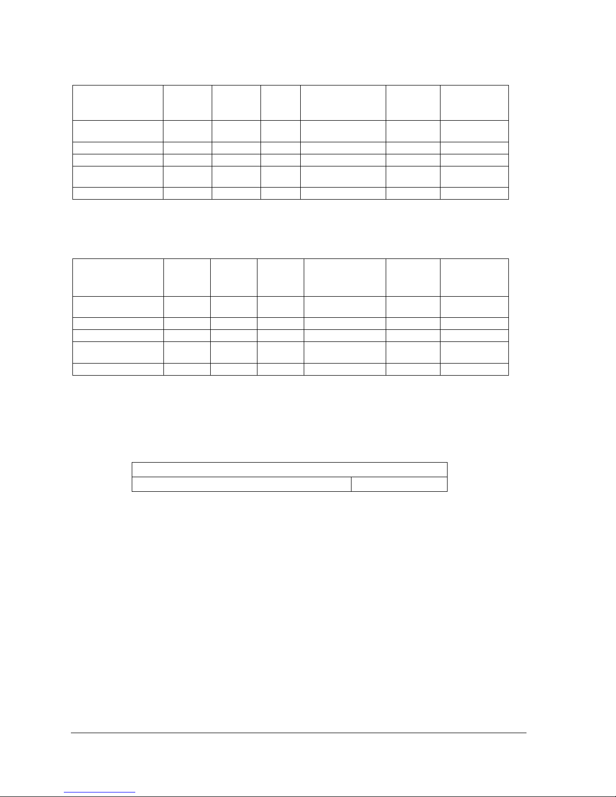
Table 4 : VoltMax 208 VAC / 60 Hz / 3 Phases
1
Model
BTU/h
kW
Amps
Elements 240V
2
Stage
max. power
supply
(MCM)3
VoltMax 79
268 695
78,75
219
7 x 15 kW
7 x 11,25 kW
3 x 350
VoltMax 90
307 080
90
250
8 x 15 kW
8 x 11,25 kW
3 x 500
VoltMax 95
322 434
94,5
263
7 X 18 kW
7 X 13,5 kW
3 x 500
VoltMax 108
368 496
108
300
8 x 18 kW
8 x 13,5 kW
3 x 500
1
Electrical supply 208 V 3 phase (L1-L2-L3) with 3 conductors Cu or AL ,90 °C with a ground.
2
240V electrical element operated at 208V
3
-Maximum capacity of the boilers connection terminals
VOLTMAX ELECTRIC BOILER Installation and Operation Manual (Revised March 2019), Page 6.
Table 5 : VoltMax 240 VAC / 60 Hz / 1 Phase
1
Model
BTU/h
kW
Amps
Elements 240V
Stage
2
max. power
supply
(MCM)3
VoltMax 77
262 724
77
321
7 x 5 kW
7 x 6 kW
7 x 11 kW
2 x 500
VoltMax 80
272 960
80
333
16 x 5 kW
8 x 10 kW
2 x 600
VoltMax 84
386 608
84
350
14 x 6 kW
7 X 12 kW
2 x 600
VoltMax 88
300 256
88
366
8 x 5 kW
8 x 6 kW
8 x 11 kW
4 x300
VoltMax 96
327 552
96
400
16 x 6 kW
8 x 12 kW
4 x 300
1
Electrical supply 240 V 2 phase (L1-L2) with 2 conductors Cu or AL ,90 °C with a ground.
2
The 10 kW stage is composed of two 5kW elements
The 11 kW stage is composed of one 5 kW element et one 6 kW element
The 12 kW stage is composed of two 6 kW elements.
3
-Maximum capacity of the boilers connection terminals
Table 6 : VoltMax 208 VAC / 60 Hz / 1 Phase
1
Model
BTU/h
kW
Amps
Elments 240V
2
Stage
3
max. power
supply
(MCM)4
VoltMax 58
197 043
57.75
278
7 x 5 kW
7 x 6 kW
7 x 8.25
kW
2 x 500
VoltMax 60
204 720
60
288
16 x 5 kW
8 x 7.5 kW
2 x 500
VoltMax 63
214 956
63
303
14 x 6 kW
7 X 9 kW
2 x 500
VoltMax 66
225 192
66
317
8 x 5 kW
8 x 6 kW
8 x 8.25
kW
2 x 500
VoltMax 72
245 664
72
346
16 x 6 kW
8 x 9 kW
2 x 600
1
Electrical supply 240 V 2 phase (L1-L2) with 2 conductors Cu or AL ,90 °C with a ground.
2
240 electrical element operated at 208V
3
The 7.5 kW stage is composed of two 5kW elements
The 8.25 kW stage is composed of one 5 kW element et one 6 kW element
The 9 kW stage is composed of two 6 kW elements.
4
- Maximum capacity of the boilers connection terminals
Table 7 : Maximum operating pressure
All models
1
Standard maximum operating pressure
160 PSI
1
Safety valeve pressure of 60 psi, 125 psi or 150 psi (Standard).
VOLTMAX ELECTRIC BOILER Installation and Operation Manual (Revised March 2019), Page 7.
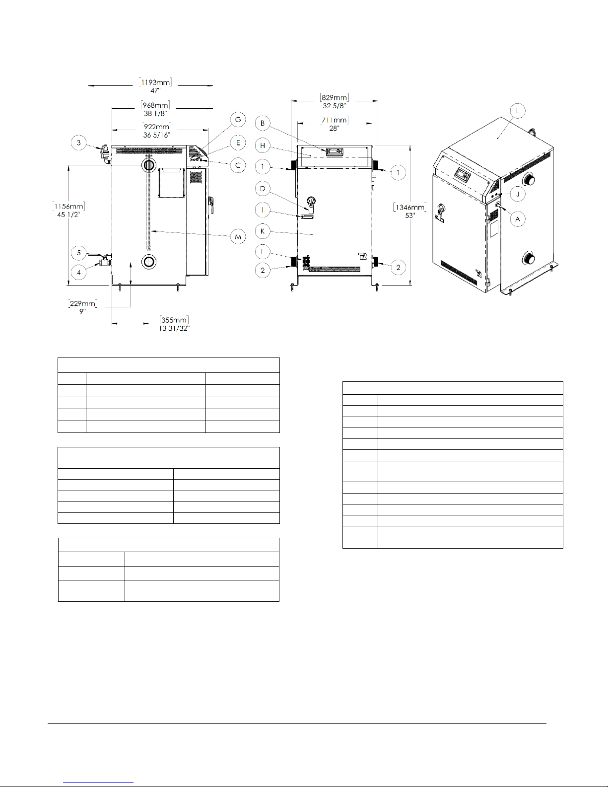
BOILER DIMENSIONS AND CHARACTERISTICS
* Optional disconnect switch available on "THREE-PHASE" models.
BOILER CONNECTIONS
1
Boiler outlet
3 " NPT M
2
Boiler inlet
3 " NPT M
3
Pressure relief valve
3/4" NPT F
4
Drain valve
1 1/4 " NPT F
5*
Access to the return sensor
1/2 " NPT F
MIN. CLEARANCES FOR INSTALLATION &
MAINTENANCE
Left and Right sides
6"/ 152mm
Rear
6"/ 152mm
Front
24" / 610mm
Bottom
0" / 0mm
Top
32" / 813mm
GENERAL INFORMATIONS
Weight
1200 lbs / 545 kg
Water Volume
62 Us gal. / 235 liters
Max. operating
pressure
STANDARD: 160psi
COMPONENTS IDENTIFICATION
A
Electrical main supply
B
Boiler controller
C
"On/Off" switch
D*
Disconnect switch & rotary handle
E
Fuses for controls
F
Solid state SCR relay
G
Low water cut-off, test button and indicator
lights
H
Electrical control access door
I
Door handle for electric access with lock
J
Electrical control wires access holes
K
Access door power circuit
L
Access cover to Heating elements
M
Heating elements
VOLTMAX ELECTRIC BOILER Installation and Operation Manual (Revised March 2019), Page 8.
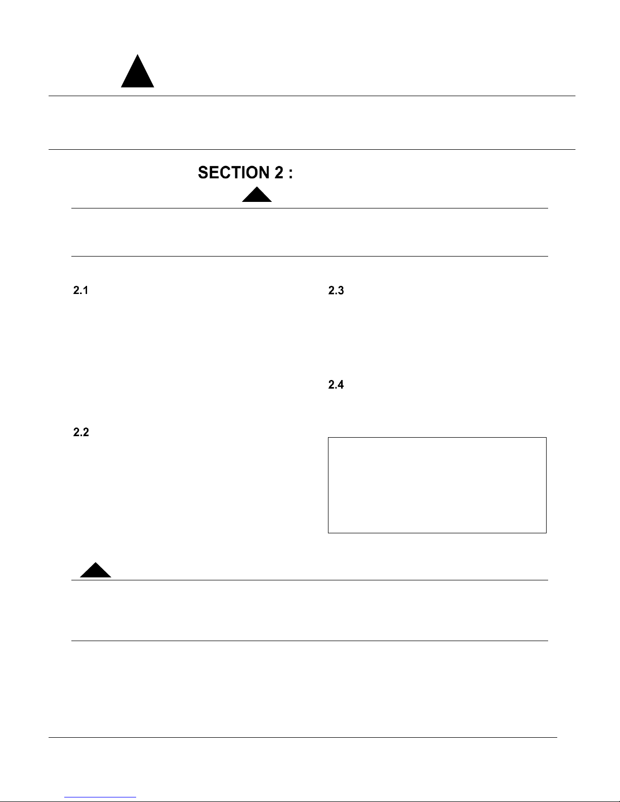
General Safety Precautions
Be sure to read and understand the entire Installation & operation manual before attempting to install or to operate this water
heater. Pay attention to the following General Safety Precautions. Failure to follow these warnings could cause property damage,
bodily injury or death. Should you have any problems understanding the instructions in this manual, STOP, and get help from a
qualified installer or technician
INTRODUCTION
These important safeguards and instruction appearing in this manual are not meant to cover all
possible conditions and situations that may occur. Common sense,
caution and care are factors that cannot be built into every product. These factors must be
supplied by the person(s) caring for and operating the unit.
LOCAL INSTALLATION
REGULATIONS
This electric boiler must be installed in
accordance with these instructions and in
conformity with local codes, or in the absence of
local codes, with the National Plumbing Code and
the National Electric Code, current edition. In any
case where instructions in this manual differ from
local or national codes, the local or national codes
take precedence.
CORROSIVE ENVIRONMENT
The electric boiler must not be installed near an
air duct supplying corrosive atmosphere or with
high humidity content. When a boiler defect is
caused by such conditions, the warranty will not
apply.
INSPECTION UPON RECEPTION
Inspect the electric boiler for possible shipping
damage. The manufacturer’s responsibility
ceases upon delivery of goods to the carrier in
good condition. The Consignee must file any
claims for damage, shortage in shipments, or
non-delivery immediately against the carrier.
TO BE CHECKED
Please refer to the rating plate on the unit to
ensure that you have the correct model and
voltage in hand.
List of components shipped with the unit:
• Pressure relief valve
• Drain valve
• Outdoor temperature sensor ¸
(Located inside the control panel of the
unit)
The electric boiler should not be installed where it may damage the adjacent structures or lower
floors in the event of leakage of the tank or connections. If this cannot be avoided, install a nonflammable tray or bowl under the boiler to collect and drain water from leaks.
NOTE: Any tray or cuvette MUST conform to local codes.
!
AVERTISSEMENT
!
WARNING
!
VOLTMAX ELECTRIC BOILER Installation and Operation Manual (Revised March 2019), Page 9.
INSTALLATION
The manufacturer’s warranty does not cover any damage or defect caused by installation, or
attachment, or use of any special attachment other than those authorized by the manufacturer into,
onto, or in conjunction with the water heater. The use of such unauthorized devices may shorten
the life of the boiler and may endanger life and property. The manufacturer disclaims any
responsibility for such loss or injury resulting from the use of such unauthorized devices
SAFETY MEASURES
Any commercial installation will be equipped with
a safety valve that limits the maximum working
pressure to the maximum design pressure of the
tank. The maximum operating pressure of the
VoltMax Boiler with a power of 90kW and less is
30 psi or 70 psi, depending on the options chosen.
The maximum operating pressure of the VoltMax
boiler with a power of more than 90kW is 60 psi or
125 psi, depending on the options selected. See
boiler data sheet for maximum operating pressure.
The boiler is equipped with an automatic high limit
temperature control set at 210°F (99°C) and a
second manual high limit temperature settable.
This electric boiler is designed to operate at a
maximum operating temperature of 200 ° F (93 °
C). The boiler is designed for use in a hot water
heating system only.
The heat transfer fluid must be water or an
antifreeze water / propylene glycol solution or
an antifreeze water / ethylene glycol solution
specially designed for heating systems. The
maximum concentration of solution must be a
maximum of 50%.
LOCATION
The electric boiler should be installed in a clean,
dry location. Long hot water lines should be
insulated to conserve water and energy. The
electric boiler and water lines should be protected
from exposure to freezing temperature.
The boiler can be mounted vertically or
horizontally directly on a solid surface.
The electric boiler must be located or protected
to avoid risk of physical damage, such as from
moving vehicles, flooding, etc.
The location must have sufficient ventilation to
maintain an ambient temperature not exceeding
80°F (27°C).
To prevent condensation on the boiler walls,
boiler temperature should not be maintained
below the condensation temperature (dewpoint temperature) of the ambient. The
operating temperature of the boiler must not
be lower than the condensation temperature
(dew temperature) relative to the ambient
humidity content.
CLEARANCES
For adequate inspection and servicing the
following minimum clearance is necessary:
Table 8 : Boiler Clearances
Sides**
3 inches / 76 mm
Bottom
0 inches / 0 mm
Top*
32 inches / 813 mm
Front
24 inches / 610 mm
Back
3 inches / 76 mm
* A minimum clearance of 32 inches. For units
equipped with 18 kW elements (25 in. For 15 kW
elements) is required for possible replacement of
heating elements.
** The left side of the control panel, where the
boiler ON / OFF switch is located, must remain
visible after installation. Otherwise, a label
indicating its location must be affixed to the
control panel indicating its position.
PIPING INSTALLATION
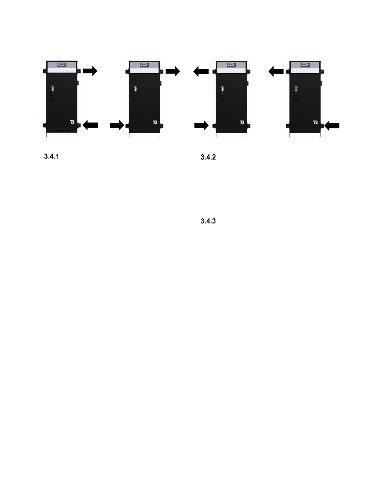
The location of the inlet and outlet piping shall
conform to the various configurations shown in
Figure 1. You will find typical connection diagrams
to the Figure 3, Figure 4 and Figure 5.
The VoltMax boiler is designed to be operated
on a closed-circuit piping system. Therefore, it
should not be used to heat open air tanks
MISE EN GARDE
!
VOLTMAX ELECTRIC BOILER Installation and Operation Manual (Revised March 2019), Page 10.
Figure 1 : Possible pipe flow configurations
BOILER PIPING CONNECTION
The boiler is equipped with two fittings on each
side of the unit. One of the bottom connections
must be used for the heating return (inlet) and one
of the top connections must be used for supplying
the heating system (outlet).
The outlet and inlet size are 1½ "NPTM threaded
steel pipes, for the VoltMax with a power of 90kW
and less and 2½ "NPTM threaded steel pipes for
the VoltMax with a power of More than 90kW.
Installation of plugs on the inlet and exhaust ducts
is required to facilitate the disconnection and
maintenance of the boiler.
When connecting different types of pipes
(galvanized steel and copper), use dielectric joints
(insulation) to protect the boiler and piping.
Use only new and clean pipes as piping
connection to the boiler. Local codes or
regulations may dictate the exact type of material
to be used.
Insulate all piping containing hot water, especially
in an unheated environment.
Install faucets for easy maintenance.
Install a thermometer on the inlet and outlet
duct(s).
Close the unused openings on the boiler. Do not
block the safety valve, this may cause loss,
damage or injury.
AUXILIARY BOILER PIPING
CONNECTION
When an auxiliary boiler used as back up is
twinned to the VoltMax boiler to act as a back-up
controlled by the VOTLMAX, the auxiliary
boiler shall be installed downstream of the electric
boiler as shown on Figure 5 and 7.
SAFETY VALVE
The installation of a safety valve is an integral part
of the boiler’s installation. The trigger point of the
valve must not exceed the design pressure of the
boiler as indicated on its registration and
identification plate. The valve must comply with the
ASME Boiler and Pressure Vessel Code and limit
the boiler maximum operating pressure. The
safety valve is a security component, not a control
component.
The capacity of the safety valve expressed in BTU
/ hour must equal or exceed the rating on the
nameplate of the boiler (s).
A safety valve adjusted to the maximum design
pressure of the boiler has been installed at the
factory. The latter can be replaced by a valve with
a lower trigger pressure, but its BTU / hour
capacity must not be lower than the maximum
boiler power.
Connect the exhaust of the safety valve to a drain
line. The lower end of this conduit shall be at least
6" (15 cm) from the floor drain away from any
electrical component. The drain line must be
directed downwards from the exhaust of the safety
valve to ensure complete drainage by gravity. The
diameter of the drainpipe must not be less than
that of the exhaust of the valve. The end of the
conduit must not be threaded or hidden and must

VOLTMAX ELECTRIC BOILER Installation and Operation Manual (Revised March 2019), Page 11.
be protected from freezing. No valves, valves or
valves shall be installed on the pipe. The
installation of the safety valves is governed by the
local code.
SYSTEM PRESSURE CONTROL
AND EXPANSION TANK
Pressure control devices within the system ensure
that each component operates within minimum
and maximum allowable pressures and maintain
minimum pressure for all normal operating
temperatures. They also allow air bleeding,
prevent cavitation at the pump inlet and prevent
water from boiling within the system; all this is
accomplished with minimal addition of new water.
The increase in boiler water volume resulting from
higher temperature is stored in the expansion tank
during periods of high operating temperature and
is returned to the system when the temperature
decreases.
The expansion tank must be able to store the
required volume of boiler water during maximum
design operating temperature without exceeding
the maximum allowable operating pressure, and to
maintain the required minimum pressure when the
system is cold. Contact your installing contractor,
plumbing supply house, or local plumbing
inspector for assistance. The point where the
expansion tank is connected should be carefully
selected to avoid the possibility that normal
operation of automatic check or manual valves will
isolate the tank from a hot boiler or any part of the
system.
The expansion tank should preferably be located
on the suction or intake side of the pump.
WATER PRESSURE MAKEUP
REGULATOR
Make-up systems must be employed as required
by codes. An automatic fill valve (automatic
pressure regulator) must be used with a backflow
preventer as required, to maintain minimum
system pressure by supplying water to make up for
leakage.
A minimum pressure of 5psi (34kPa) must be
maintained at all times.
A backflow prevention device that complies with
local standards must be installed upstream of the
pressure regulator.
AIR BLEEDER
The air contained in the heated water must be
removed from the system to allow the proper
functioning of the heating system and the boiler.
Installation of manual or automatic air vents is
required to eliminate all air from the boiler and the
heating distribution system.
The main air eliminator must be installed near the
outlet of the boiler on the highest point of the main
supply piping. It is imperative to ensure that all air
possibly located in the boiler be eliminated at all
time.
Regularly purge air from the pipes and beware that
the heated water does not cause injury or damage.
If the boiler is located at a location higher than the
heat distribution system such as a heated floor, an
automatic air eliminator should be installed close
to the boiler outlet.
CIRCULATING PUMP
The pump capacity required is determined in
relation to the capacity of the boiler installed and
the type of heating distribution system on which it
will be connected.
They are generally designed for an operation at a
differential of temperature (Delta T0) of 10 to 20F
between the supplies and return temperature to
the boiler.
Use the following equation to determine the
required water flow.
Pump flow rate = Boiler power ÷ Delta T ÷ 500
• Pump flow rate is expressed in US gallons per
minute or GPM.
• The Boiler output (in net BTU per hour) is the
maximum amount of heat to be transferred
through the heating loop to meet the heating
load.
• Delta T: The boiler water temperature drop
For example, an electric boiler rated at 180KW has
an output capacity of 614 160 BTU per hour. The
system is designed for a temperature drop of 20°F.
Required pump flow rate = 614,160 20 500 =
61,4 GPM
VOLTMAX ELECTRIC BOILER Installation and Operation Manual (Revised March 2019), Page 12.
For example, an 180kW electric boiler has a power
of 614,160 BTU/h. The system is designed for a
drop-in temperature (Delta T) of 20°F.
Flow required = 614,160 20 500 = 61.4 GPM
N.B. To achieve proper operation, a minimum flow
must be present when a heating request is applied
and the heating elements are in operation. In the
table below, the column representing a differential
of 50°F indicates the minimum recommended flow
for each boiler output. Installation of a flow switch
is not mandatory. If installed, its contact must be
connected between 24V+ and W1 (operation
authorization)
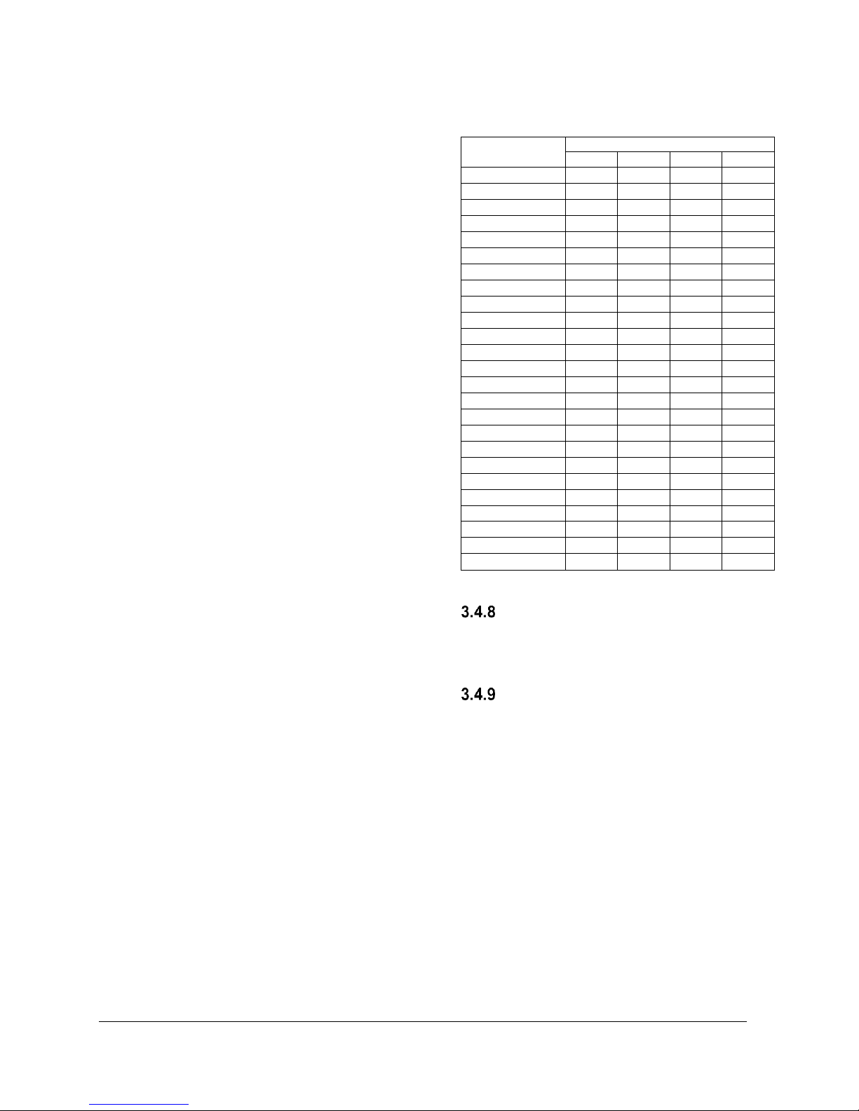
The following table lists the required pump flow
rate in relation to the boiler capacity and Delta T.
Table 9 : Temperature rise vs flow rate
(GPM)
MODEL
DELTA T0
10oF
20oF
30oF
40oF
VoltMax 77
52,5
26,3
17,5
13,1
VoltMax 80
54,6
27,3
18,2
13,6
VoltMax 84
57,3
28,7
19,1
14,3
VoltMax 88
60,1
30,0
20,0
15,0
VoltMax 96
65,5
32,8
21,8
16,4
VoltMax 105
71,7
35,8
23,9
17,9
VoltMax 120
81,9
40,9
27,3
20,5
VoltMax 126
86,0
43,0
28,7
21,5
VoltMax 144
98,3
49,1
32,8
24,6
VoltMax 192
131,0
65,5
43,7
32,8
VoltMax 204
139,2
69,6
46,4
34,8
VoltMax 216
147,4
73,7
49,1
36,8
VoltMax 225
153,5
76,8
51,2
38,4
VoltMax 240
163,8
81,9
54,6
40,9
VoltMax 255
174,0
87,0
58,0
43,5
VoltMax 270
184,2
92,1
61,4
46,1
VoltMax 288
196,5
98,3
65,5
49,1
VoltMax 306
208,8
104,4
69,6
52,2
VoltMax 315
215,0
107,5
71,7
53,7
VoltMax 324
221,1
110,5
73,7
55,3
VoltMax 336
229,3
114,6
76,4
57,3
VoltMax 357
243,6
121,8
81,2
60,9
VoltMax 378
257,9
129,0
86,0
64,5
VoltMax 384
262,0
131,0
87,3
65,5
VoltMax 408
278,4
139,2
92,8
69,6
*Minimum flow
DRAIN FAUCET
A drain valve is installed behind the unit. It allows
the boiler to be emptied, to make possible the
replacement of defective components.
SIEVE
A sieve or other accessorie that collects sediments
should be installed on systems where high particle
concentration may existe. Sediments may
eventually get to the elements and cause damage
to the elements. The warranty does not cover
damages in this case.
VOLTMAX ELECTRIC BOILER Installation and Operation Manual (Revised March 2019), Page 13.
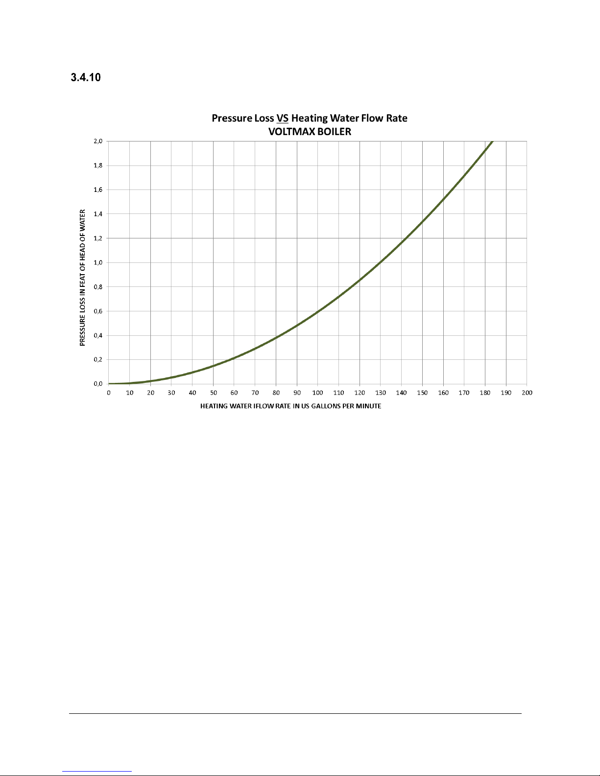
PRESSURE LOSS
The graph of pressure loss due to flow of water inside the VoltMax boiler is shown in the following figure.
Figure 2 : Pressure loss (FTH) as a function of the flow rate of heated water (GPM)
VOLTMAX ELECTRIC BOILER Installation and Operation Manual (Revised March 2019), Page 14.
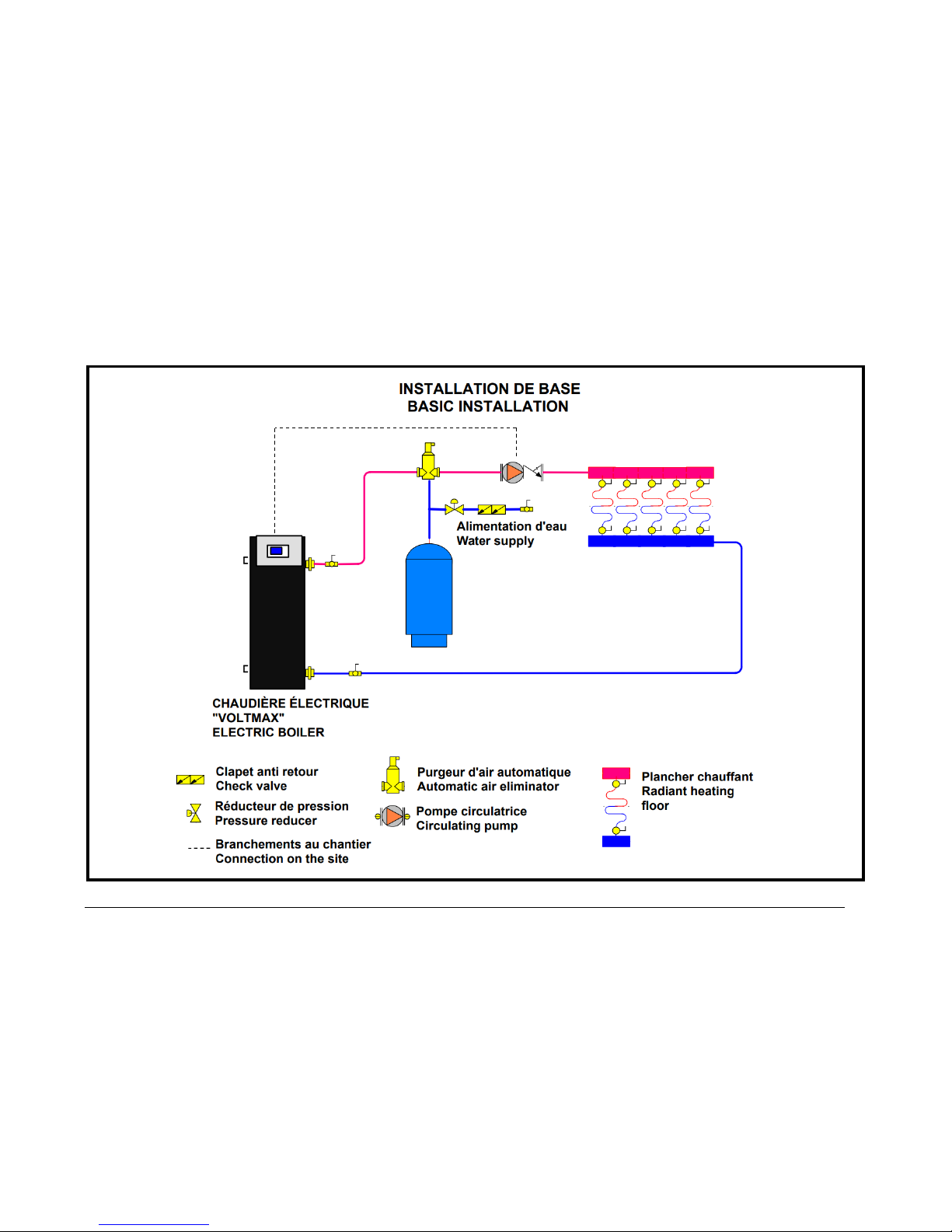
Figure 3 : Basic installation
VOLTMAX ELECTRIC BOILER Installation and Operation Manual (Revised March 2019), Page 15.
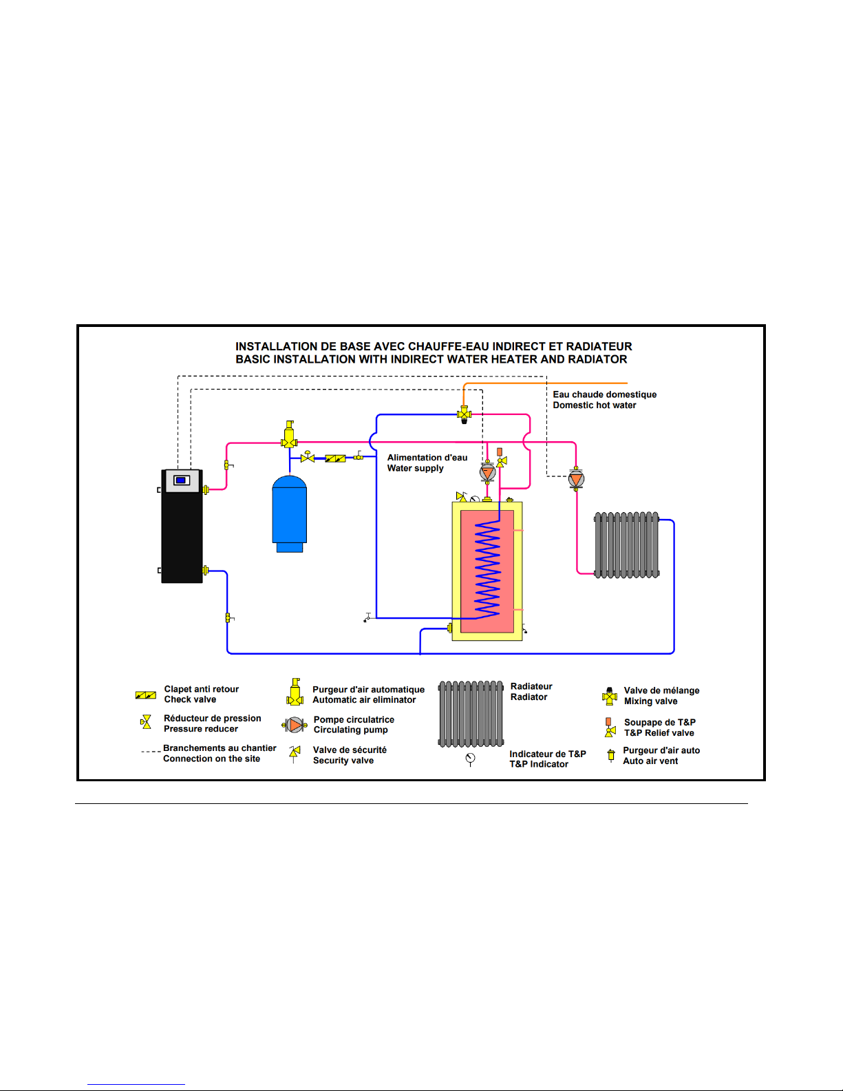
Figure 4 : Basic installation with indirect water heater and radiator
VOLTMAX ELECTRIC BOILER Installation and Operation Manual (Revised March 2019), Page 16.
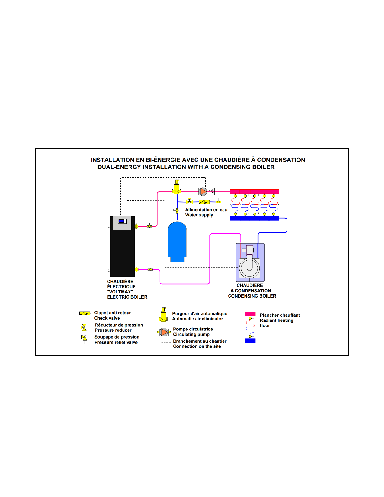
Figure 5 : Dual-Energy installation with a condensing boiler
VOLTMAX ELECTRIC BOILER Installation and Operation Manual (Revised March 2019), Page 17.
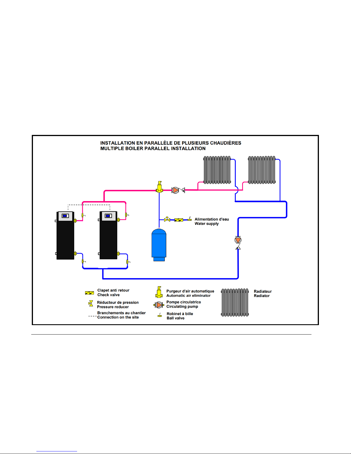
Figure 6 : Multiple boiler parallel installation
VOLTMAX ELECTRIC BOILER Installation and Operation Manual (Revised March 2019), Page 18.
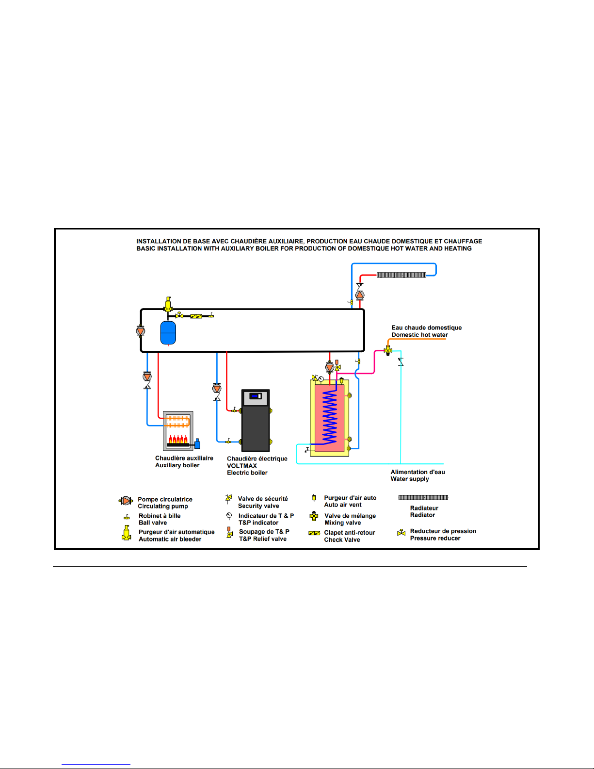
Figure 7 : Basic installation with auxiliary boiler for production of domestic hot water and heating

VOLTMAX ELECTRIC BOILER Installation and Operation Manual (Revised March 2019), Page 19.
ELECTRICAL CONNECTIONS
Wiring must conform to the National Electrical
Code and to state or local code requirements.
The electric boiler must be electrically grounded in
accordance with local codes, or, in the absence of
local codes, with the National Electrical Code.
MAIN ELECTRICAL SUPPLY
The power supply must be a 208 or 240-volt circuit
(single-phase or three-phase, 60Hz), 480 volts
(three-phase, 60 Hz) or 600 volts (three-phase, 60
Hz) protected by an appropriately sized breaker.
Refer to the boiler rating plate to select the breaker
capacity and wiring rating
Alimentation cables can be in copper or
aluminium.
The used cable gauge shall not be greater than the
maximum size allowed by the connection
terminals. See tables 1 through 6 for the specific
values.
PUMP SUPPLY
The VoltMax Electric boiler can control 1 or 2
pumps of the distribution system. According to the
VoltMax configuration, the contact of the pump will
function differently.
During a heat demand on W1 or W2, the contact
between Pc and P1 or Pc and P2 will be used to
start an external pump relay (maximum of 3
amps.). Depending on the configurations selected
in the controller, the pump P2 can have priority
over the pump P1.
N.B. The VoltMax boiler is not designed to heat
without a water circulation in its tank. Therefore, if
external pump controls are used, they must be
interlocked with the operating authorization on W1
and/or W2 of the controller.
CONNECTION OF EXTERNAL
SIGNALS TO THE CONTROLLER
The connection of all external signals is made
directly on the boiler controller on terminals
located on top of it. See the connection diagram
on
Figure 8
Cables used for the connections shall resist
temperature up to 90 °C.
Connecting the building heat demand
signal or running authorization
Upon reception of a closed contact connected to
terminals 24V+ and W1 or W2, the corresponding
circulating pump P1 or P2 will start and the boiler
will be allowed to operate.
If external controllers control the heating system
pumps, they must provide the operating
authorization signal. The boiler must not receive a
heat demand without the circulation pumps
running.
On heating systems when water circulation is
continuous, the heat demand control can be
connected in series with the pumps interlocks to
the 24V+ and W1 terminals. The heating elements
will then be active and available only when there is
a request (dry contact).
If the heating system is designed to keep water
warm with continuous circulation, a dry contact
from the pumps relay or a contact from a flow
sensor must be connected on the 24V+ and W1
terminals to maintain the boiler in demand as long
as the pumps are in function. The boiler will then
attempt to maintain the water temperature at the
set-point.
Operation with an upper fixed set-point W2 can be
established by connecting the auxiliary heating
demand signal (Dry contact) of a thermostat to the
24V+ and W2 of the terminal block.
In all operating modes of the controller, a heat
demand on W1 and W2/DHW (close contact) must
be present to DI1 or DI2 to allow the operation of
the boiler. The only exception is in domestic hot
water mode (DHW) with an indirect water heater
where the minimum boiler temperature shall be
maintained.
Connecting an auxiliary boiler
The boiler controller is designed to allow the
operation of a second boiler or an auxiliary boiler
according to two different mode of operation
“Auxiliary Backup” or Dual-Energy”.
To do so, connect the TT terminals of the auxiliary
boiler to terminals AUX of the VoltMax. The
maximum capacity of this contact is 3A/120Vac.
See section 4.3.4 for details.

VOLTMAX ELECTRIC BOILER Installation and Operation Manual (Revised March 2019), Page 20.
Connection of an “Unoccupied signal”
of the building.
This function allows dropping the boiler
temperature during periods where the building is
not used and this without having to lower all the
room thermostats of the building.
To do so, a signal (dry contact) will have to be
connected to terminal OCC. The contact shall be
close during the periods of temperature drop.
You can also manage the periods of temperature
drop by setting a schedule in the controller.
Connection of an indirect domestic
hot water heater
The VoltMax electric boiler can be used not only to
fill the heating requirements of the building but also
to fill its domestic hot water needs using an indirect
domestic hot water heater such as our
TURBOMAX series.
To do so, connect the signal (dry contact) of
indirect water heater temperature control to the
terminal 24V+ and W2/DHW This will activate the
circulating pump supplying the water heater (if
properly installed).
Connection of a dual-energy signal
The VoltMax can be operated in a dual-energy
mode with an auxiliary boiler.
To do so, connect the normally close contact of the
dual energy controller to terminals 24V+ & BI-E to
operate with the electric boiler. See section
4.3.4.5 for more details on the sequence of
operation in dual energy.
Connection of an outdoor temperature
sensor
If you wish to modulate the boiler water
temperature according to the outdoor temperature
(Outdoor Reset, ORST) and also wish to stop the
operation of the boiler when the outdoor temp.
reaches a selected value, then the outdoor sensor
supplied with the unit or a corresponding signal
coming from the network system shall be
connected with a cable of minimum gauge 20 (max
100pi) to terminals S. Ext. of the controller.
This probe does not need to be connected during
an operation with a fixed setpoint temperature
unless you want to use the Warm weather
Shutdown function.
N.B. Do not install a jumper if the outside sensor
is not used.
Outdoor sensor location
o Outside the building at a location that best
represents the heat demand of the building (a
wall facing north for most of the buildings and
on a south one on buildings with large
windows facing south).
o It should not be exposed to external heat
sources (dryer outlet, window openings, noninsulated walls).
o It should not be installed in a location where it
could be covered with snow.
Remote controller used to determine
the target boiler temperature
An external controller (such as a central building
energy management system) can be used to
determine the boiler target temperature required
for the building.
On every model this can be done by a BACnet
communication.
Also, an external controller shall give a 0 to 10VDC
signal connected to terminals 0-10Vdc G & 0-
10Vdc T° of the controller.
Limit Capacity 0-10VDC
On every model this can be done by a BACnet
communication.
An external controller providing a 0-10Vdc signal
could be used to manage the capacity (kW) of the
boiler.
Example: An application where the main electrical
service supply of the building is limited or when the
electricity rate is billed according to the maximum
peak loads of the building. To do so, the external
controller shall be connected to terminals 0-10Vdc
G & 0-10V cap. The capacity of the boiler could be
manually limited by adjusting some of the
controller parameters. See section 4.3.4 for more
details.

VOLTMAX ELECTRIC BOILER Installation and Operation Manual (Revised March 2019), Page 21.
External alarm contact
An alarm signal (dry contact) is available on the
boiler to advise the user of an alarm situation. The
capacity of the contact is 5A resistive/1A inductive
on terminal AL/AL.
The dry contact between contactors AL/AL is
normaly open and will close in the event that any
of the following conditions appears:
• A temperature high limit
• A low level of water (if included)
• Électric power loss or the control switch is
at OFF.
An internal audible alarm inside the controller is
available on all models. Just activate it in the
settings.
Connecting an external high
limit (EXT.HL)
An additional high limit control (pressure,
temperature, flow, water low level…) could be
required in a particular application. It shall be
installed outside of the unit and its contact shall be
connected the EXT. HL contactor of the terminal
bloc after removing the current jumper. This
contact is installed in series with the internal high
limits of the boiler and will stop completetly the
boiler and even engage a lock out if the contact
persists. Consequently, this contact shall not be
used to turn on the boiler. The heat demand or
running authorization should be connected on W1
or W2.

VOLTMAX ELECTRIC BOILER Installation and Operation Manual (Revised March 2019), Page 22.
Figure 8 : ELECTRICAL CONNECTIONS OF THE INPUT AND OUTPUT SIGNALS TO THE CONTROLLER

VOLTMAX ELECTRIC BOILER Installation and Operation Manual (Revised March 2019), Page 23.
CONTROLLER OPERATION
USER INTERFACE
The control of the boiler is ensured by a controller
TM171PFE03 from the Schneider Electric
company. The LCD display of the controller
provides an interface for configuring and
displaying the boiler parameters and status.
A communication module also allows you to
integrate the controller with an intelligent building
management system (BACnet protocol). It is also
equipped with an Ethernet connection. Allowing
the connection to the Internet network of the
building allowing reading and modifying locally or
remotely the boiler setting. It can be configured to
send alarm messages via e-mail.
Icons will also display to indicate the boiler’s
current operating status. Temperature can be
displayed in Celsius or Fahrenheit and text can
be set to either English or French.
The controller has a backlight function. It is also
equipped with three indicator lights (Green /
Yellow / Red). The green light indicates normal
operation of the unit; the yellow light indicates that
the controller has diagnosed and anomaly which
requires verification by a technician. The red light
indicates that the unit is currently in a critical state
(high temperature alarm) or in lock out mode.
More detail is provided in Section 6:
Troubleshooting. The controller can also be
configured to activate an internal buzzer and
activate an external alarm signal when an alarm
condition occurs causing the boiler to fail.
Figure 9 : Illustration of the display
SYMBOL DESCRIPTION
The main display shows most the boiler operation
status information. The explanation of the main
display is shown below.
Boiler operating mode
W1
Heating request 1 : On
W2
Heating request 2 : On
BIE
Boiler in Bi-Energy mode
VoltMax Boiler : On
Auxiliary boiler : On
Boost mode : On
Warm Weather Shut Down : On
Alarm symbol
An alarm is active
The boiler is in lock out mode
HL
High temperature limit condition at
the boiler outlet
LL
Low temperature limit conditions
(lack of capacity)
P
Alarm due to a pressure problem
A
Alarm due to an electrical problem
F
Alarm due to a flow problem
Se
Alarm due to a sensor problem
The internal clock battery level is low
Operating state of the boiler
T° SETPOINT
Actual set-point temperature
T° BOILER
Water temperature at the
outlet of the boiler
CAP (%)
Percentage of power used
according to boiler rated
power
T° EXT
Outdoor temperature
measured using the outdoor
sensor
KW ACT
Actual power calculated by
the boiler
PRESS.
Pressure inside the boiler
STAGE
Status of active stage
VOLTMAX ELECTRIC BOILER Installation and Operation Manual (Revised March 2019), Page 24.
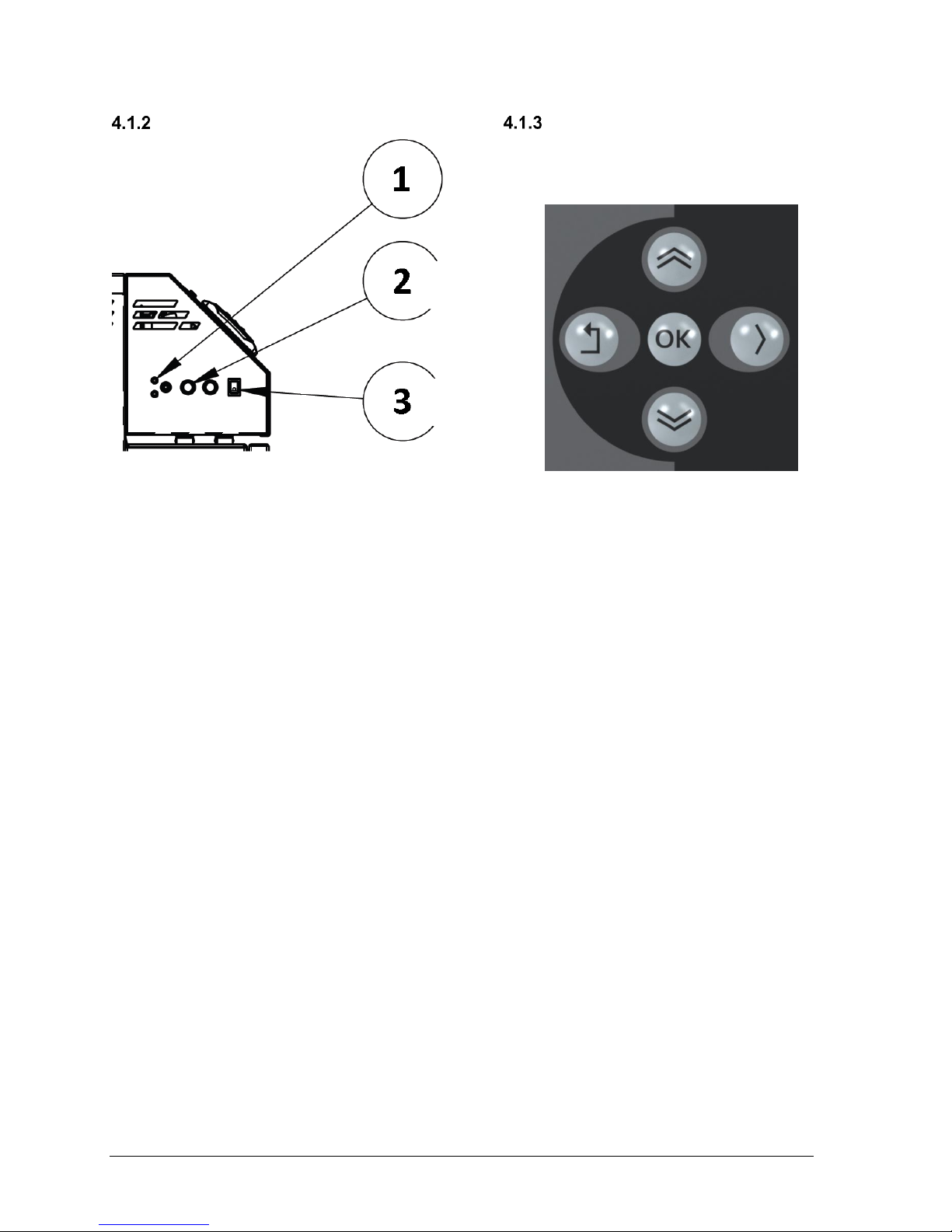
CONTROL PANEL
Figure 10 : Control panel
On the left side of the appliance, an on / off switch
(# 3) is used to operate the appliance and to reset
the boiler.
An indicator light showing the status of the low
water level cut off and a test button (# 1). The
control circuit fuses (# 2) are accessible from the
left side of the unit.
NAVIGATION AND
ADJUSTEMENTS
The navigation within the display is done with the
five pushbuttons on the right of the screen.
Navigation between the elements is done with the
up and down arrows. Use the right key to change
the page in the menus. The return key will bring
you to the previous menu. The return key returns
you to the main display when it is pressed for 2
seconds or more.
The OK button confirms the selection and allows
you to edit a parameter. Only highlighted box can
be modified. To modify an option, select the box
to modify with the arrow keys and press OK. The
black box or one of its values will flash and can
be changed. Change the values using the arrows
and confirm the change by pressing OK.
1 2 3
4
VOLTMAX ELECTRIC BOILER Installation and Operation Manual (Revised March 2019), Page 25.
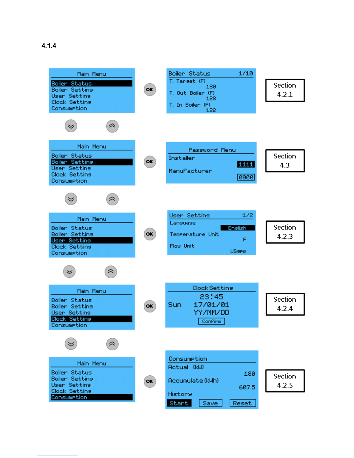
MAIN MENU NAVIGATION
Press one of the 5 buttons on the main display to access the main menu
Figure 11 : Main menu navigation
VOLTMAX ELECTRIC BOILER Installation and Operation Manual (Revised March 2019), Page 26.
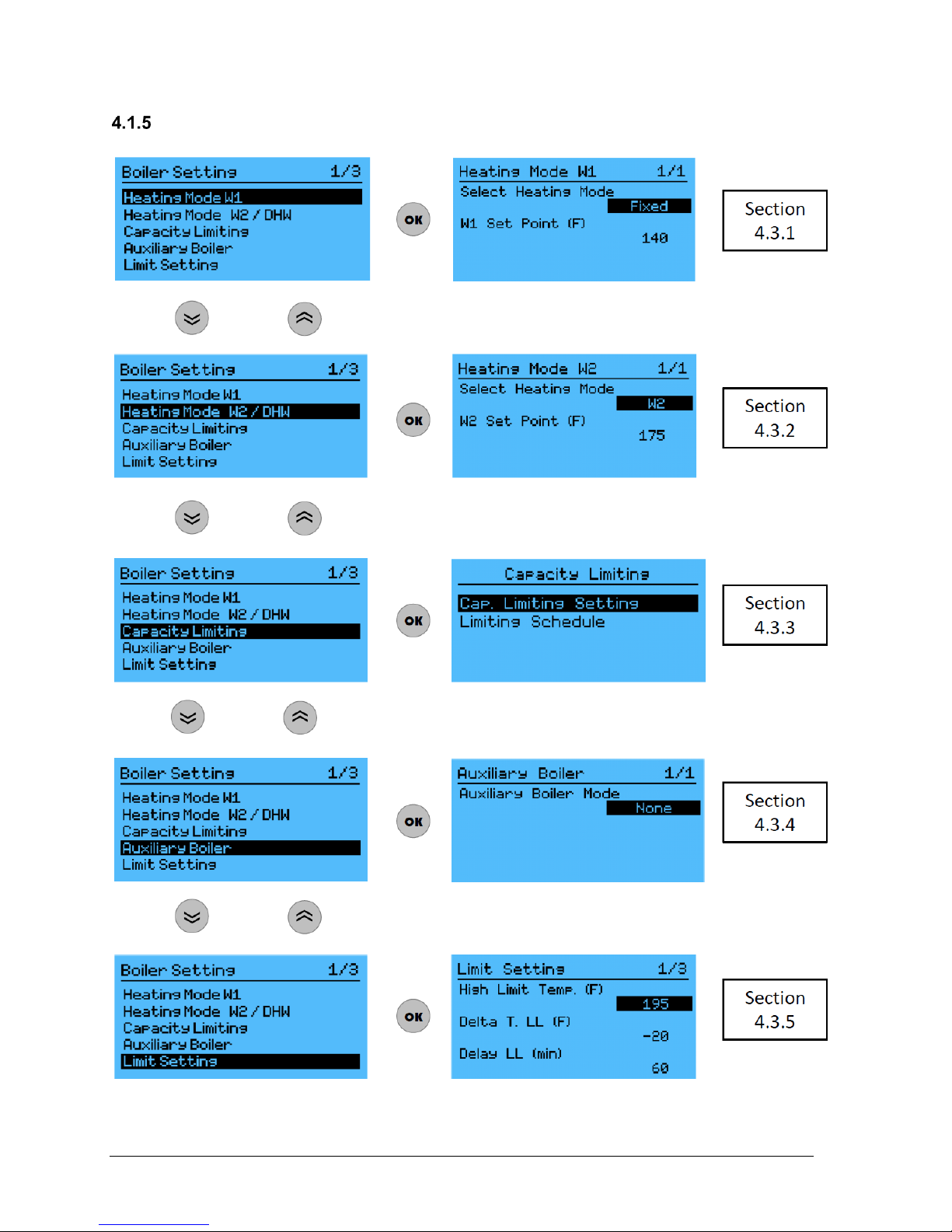
NAVIGATION IN BOILER SETTING
Figure 12 : Navigation in boiler setting menu (1/3)
VOLTMAX ELECTRIC BOILER Installation and Operation Manual (Revised March 2019), Page 27.
You can switch from page by using the left or right arrow (Ex : 1/3 to 2/3 by using the
right arrow)
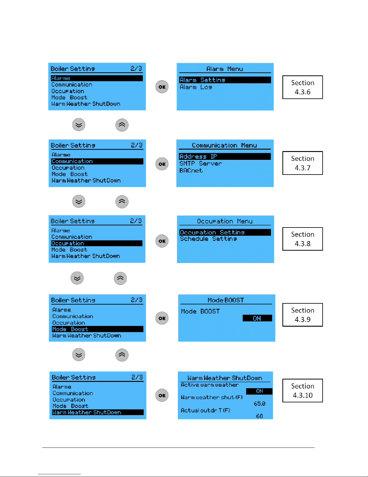
Figure 13 : Navigation in boiler setting menu (2/3)

VOLTMAX ELECTRIC BOILER Installation and Operation Manual (Revised March 2019), Page 28.
Figure 14 : Navigation in boiler setting menu (3/3)
VOLTMAX ELECTRIC BOILER Installation and Operation Manual (Revised March 2019), Page 29.
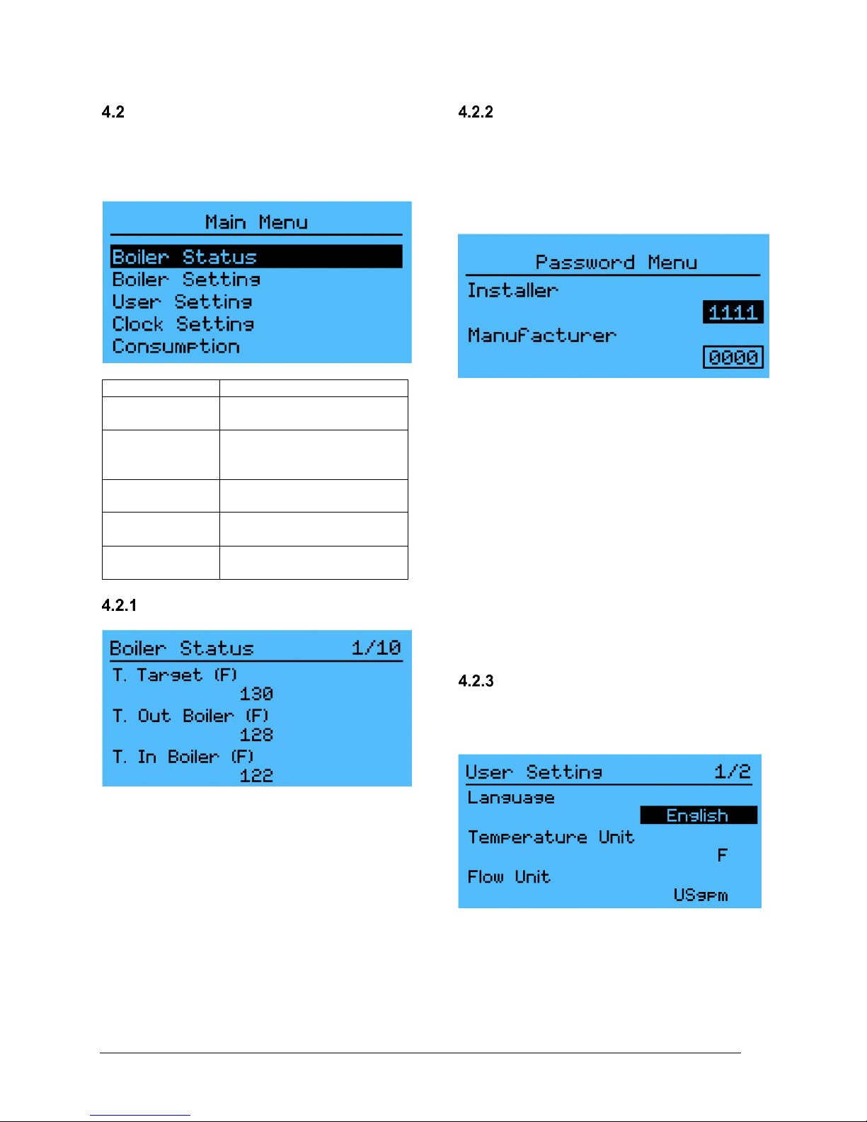
MAIN MENU
The main menu is accessible to the user, no
access code is required.
The main menu is accessed by pressing one of
the 5 pushbuttons. Navigation between menus is
done with the arrows (up, down, left and right).
Menu
Contents
Boiler status
Detailed information on the
boiler condition
Boiler setting
Configuration of the boiler
operating mode and
parameters.
User setting
Configuration of the
controller display option
Clock setting
Configuration of the
internal clock
Consumption
Power consumption of the
boiler
BOILER STATUS
Detailed information on the boiler condition
This menu allows the display of data not included
in the main display. The boiler status menu
displays the measurements of temperature,
pressure, flow, alarm summary, version of the
programme and the status of the heating
element.
The set of variables presented in this menu are
presented in Section 4.5
BOILER CONFIGURATION
Configuration of the boiler operating mode
This menu is accessible only to the installer or to
an authorized person.
The default installator password is 1111
To enter the password:
-Press up or down arrows until the “installer”
rectangle becomes black, then press “OK”.
-Press the up arrow once the change from 0 to 1.
-Press left arrow and the second number will be
selected. Press the up arrow to change from 0 to
1
-Proceed the same way the enter the other
numbers. Press OK when done.
The options in the Boiler setting menu are
detailed in Section 4.3.
The Manufacturer access code gives access to
advanced operating parameters that are not
accessible to the installer and the user.
USER SETTING
Configuration of the controller display option
This menu allows the modification of different
display parameters.
VOLTMAX ELECTRIC BOILER Installation and Operation Manual (Revised March 2019), Page 30.
Parameters
Description
Language
Select English or French
version
Temperature
unit
Select the temperature units,
either Celsius (C) or
Fahrenheit (F)
Flow unit
Select the flow unit, either US
gallons per minute (USgpm)
or liters per second (L / sec)
Backlight
Setting the backlight mode:
- Off
- 30 secondes
- Always On
Internal
buzzer
ON/OFF setting of the
internal buzzer
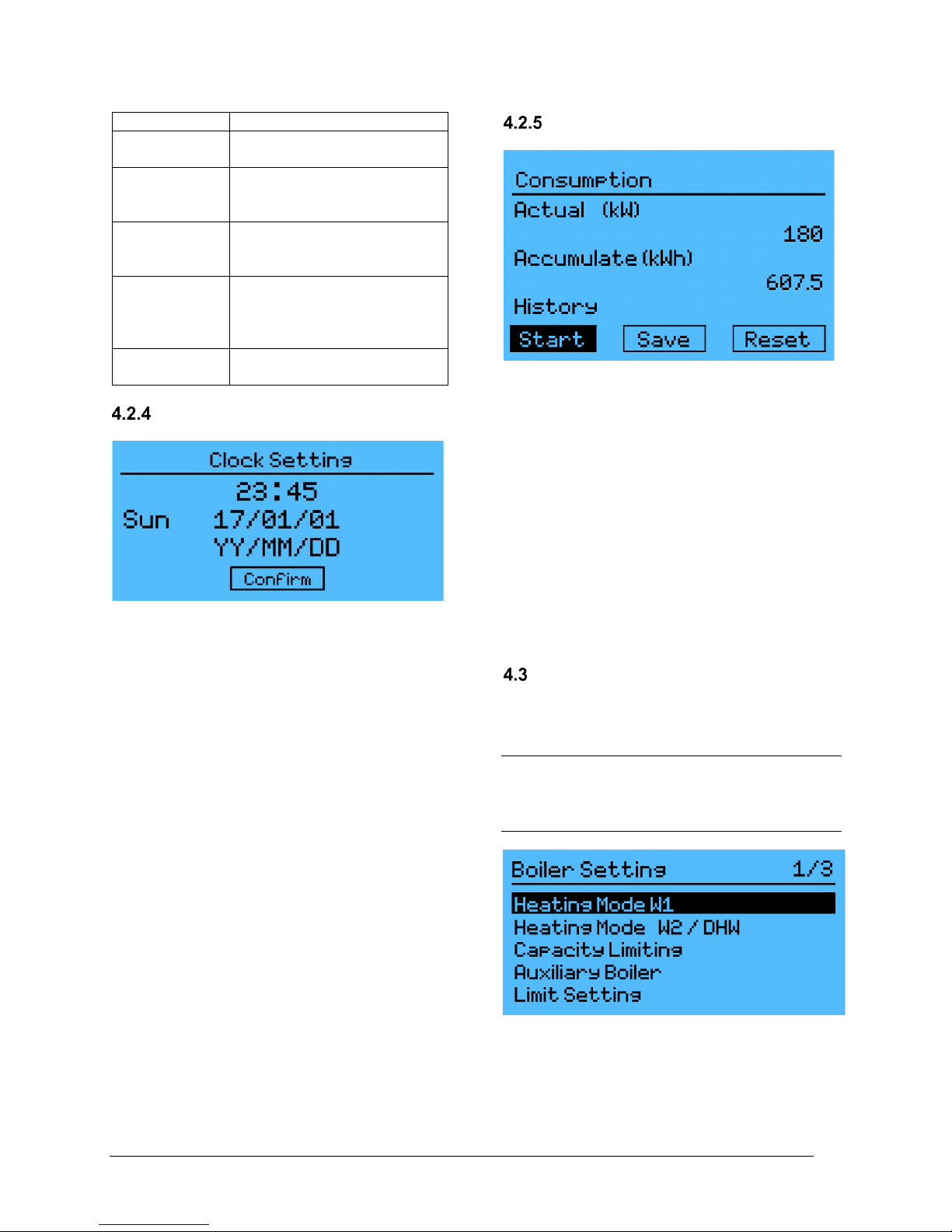
CLOCK SETTING
Internal clock configuration
Use this menu to adjust the controller’s internal
clock. To set the clock correctly, you must adjust
the time, minutes, and date.
This adjustment is necessary in order for these
modes to function properly:
- The boiler’s power consumption
- Limiting the boiler’s power capacity according to
a schedule
- The boiler’s occupation mode
Battery life for the clock is at least 1 year when
the controller is unpowered (at 25°C). When the
battery is low an indicator will appear on the
screen. The battery shall be replaced to keep to
clock active. Following a battery replacement, the
internal clock must be reprogrammed to remove
the indicator on the bottom of the screen.
CONSUMPTION
Boiler consumption cycle report
This menu allows visualization of the boiler power
consumption report. First, you must activate the
beginning of the consumption cycle with the Start
key. The consumption report can be saved using
the Save key. And all saved report is available on
the History tab. The beginning of the
consumption cycles can be reset using the Reset
button.
The controller records up to 30 consumption
report.
N.B The consumption values are approximate
and should not be used as a comparison with
actual consumption data charged by the
electricity distributor.
BOILER SETTINGS
In order to be able to configure the boiler, it is
necessary to authenticate yourself with an
installer or manufacturer code.
The default "Installer" access code is
1111 and can be changed in the
Change password menu.

VOLTMAX ELECTRIC BOILER Installation and Operation Manual (Revised March 2019), Page 31.
HEATING
MODE W1
Boiler heating mode W1
configuration according to
the type of application
HEATING
MODE
W2/DHW
Boiler heating mode W2 or
DHW configuration according
to the type of application
CAPACITY
LIMITING
Capacity limiting mode
configuration
AUXILIARY
BOILER
Auxiliary boiler mode
configuration (if needed)
LIMIT
SETTING
Configuration of the boiler
operating limits
ALARM
Configuration of the
alarms
COMMUNICATION
Configuration of the
boiler communication
parameters (Web,
Email, Bacnet)
OCCUPATION
Configuration of the
occupation parameter
mode
MODE BOOST
Enable Boost mode
WARM WEATHER
SHUTD.
Enable warm weather
shut-down function
CHANGE
PASSWORD
Changing the Installer
password
HEATING MODE W1
Selection of the operating mode
In this menu you must select an operating mode
for selecting the desired setpoint temperature
depending on the application. A heat demand or
a demand must be present on W1 and/or
W2/DHW so that the boiler can heat up.
Otherwise the boiler will indicate “---“
During a heat demand, the boiler activates
(depending on a PID curve) the number of stages
required in sequence so that the boiler output
temperature is maintained at the approximate
set-point temperature.
Here is the list of W1 heating modes:
FIXED
Fixed boiler set-point
DDC 010 VDC
Modulation of the boiler set-point
using a 0-10VDC signal
OUTD
RESET
Modulation of the boiler set-point
using the outdoor temperature
STOP
No heating demand on W1
Fixe
This mode is used for an installation where it is
desired to have a fixed set-point temperature.
If the boiler is thermostat-controlled with a heat
demand signal on W1, the boiler uses the
corresponding set-point (T. Set-point W1) as the
supply temperature.
DDC 0-10 VDC
This operating mode allows modulating the boiler
set-point temperature according to a 0-10VDC
signal applied the terminal 0-10VDC and bornier
0-10Vdc G et 0-10Vdc T, produced by an
external controller (Ex: Building Energy
Management Controller).
The details of the parameters in this mode are
presented in Section 4.6.3.

VOLTMAX ELECTRIC BOILER Installation and Operation Manual (Revised March 2019), Page 32.
Outdoor reset
This operating mode makes it possible to
modulate the boiler output set-point temperature
as a function of the outdoor temperature.
The outdoor temperature signal comes from the
temperature sensor supplied with the boiler,
which will be connected to the boiler controller.
The details of the parameters are presented in
Section 4.6.2.
Stop
Select this mode to stop the boiler. The heating
elements will not operate on a W1 demand.
HEATING MODE W2/DHW
This mode allows you to configure a second
heating demand (W2) or a demand from an
indirect domestic water heater (DHW).
Select none if none of these functions are used.
These modes are presented in detail in Section
4.7 .
W2
This mode allows the W2-DHW input to be used
to receive a signal (dry contact) from a 2nd stage
of heating.
When the contact on W2-DHW closes, the setpoint temperature changes to the set value (T.
Set-point W2), even if there is no demand on W1.
DHW
This mode allows you to configure the demand for
an indirect domestic water heater. When the
DHW mode is selected, the boiler is kept at a
minimum temperature (T. Min Boiler) and when
contact W2 closes (Dry contact) the set-point
rises to T. DHW Set-point. In addition, the PID
curve is more aggressive.
CAPACITY LIMITING
Adjusting the maximum authorized power
This menu allows you to configure the boiler
output limit. The selection of the limit mode can
be selected in the Capacity limiting menu
o None
o Manual
o DDC 0-10 VDC
o T. Ext
o Schedule
Details of each of these options are presented in
Section 4.8 .
N.B: It is not recommended to disconnect one of
the power relays inside the VoltMax boiler to
accomplish this function.
None
The boiler is not limited in power, the maximum
power it can deliver is equivalent to its maximum
rated power.
Manual
The maximum capacity permitted of the boiler is
configured in a fixed mode.
Details of the variables in this mode are
presented in Section 4.8.1
DCC 0-10 VDC
A 0-10 VDC signal from a building management
system can be used. The signal is treated as a
function in order to limit the maximum power.
In order to configure this mode, you must connect
the 0-10 VDC signal to the terminal block 0-
10Vdc Cap. and 0-10Vdc G.
Details of the variables in this mode are
presented in Section 4.8.2
T. ext
The maximum permitted power can be adjusted
according to the outside temperature sensor. The
outdoor temperature is used in order to limit the
maximum authorized power.
Details of the variables in this mode are
presented in Section 4.8.3.
This mode of operation is particularly
advantageous in applications where the boiler is
connected to an electrical network taking account
of demand peaks in order to determine the cost
of use (demand meter). Since the boiler will thus
be limited to a maximum power which will have to
be established as a function of the heating
requirements of the building and the outside
temperature, it will thus be possible to avoid
peaks of power not required to satisfy the heating
needs in periods of cold weather.

VOLTMAX ELECTRIC BOILER Installation and Operation Manual (Revised March 2019), Page 33.
Schedule
The maximum authorized boiler power can be
programmed according to a schedule. See
section 4.8.4 for an explanation of how to modify
a schedule.
AUXILIARY BOILER
The controller program has been designed to
allow the operation of a second boiler or auxiliary
boilier.
Select setpoint source for Auxiliary
Boiler
The source of the set-point temperature control
can be configured by selecting STPT source
Aux. consequently.
In the VoltMax mode, the terminal contact Aux
closes when there is a request for W1 or
W2/DHW and the VoltMax output temperature is
below the setpoint temperature. In addition, the
Aux contact is opened when the output
temperature is higher than the setpoint
temperature.
In AUXILARY mode, the Aux contact closes
when there is a request on W1 or W2 / DHW
regardless of the boiler output temperature
VoltMax. The VoltMax boiler thus has no set
temperature and is only used to activate the
auxiliary boiler relay. The various configurations
of the Aux boiler mode are the following:
None
No auxiliary boiler is present
Backup
Aux.
This mode allows the adjustment of
a second boiler to play a Backup
role
Ext
Contact
Select the heating source using
external contact to the BI-E
terminal.
BiE (BI-
Energy)
Select the heating source using
external contact to the BI-E terminal
with the possibility of support
mode of the auxiliary boiler.
Manual
Manually select the system
operation mode (Electrical or
Auxiliary).
N.B. The auxiliary boiler can only be switched on
when a heat demand is present on W1 or / and
W2 / DHW.
None
This mode must be active when there is no
auxiliary boiler on the hydronic heating system.
Backup Aux.
The boiler will be activated according to the
configuration of the lack of capacity of the
VoltMax boiler.
In the event of a lack of capacity, the boiler is
started to compensate.
The lack of capacity is defined by the fact that the
boiler output temperature is less than X degrees
(Delta T. Start Aux.) relative to the set-point for
duration of X min. (Auxiliary Start Delay). The
auxiliary boiler will be deactivated when the
temperature differential between the water outlet
temperature and the set-point temperature is
lower than Delta T. Off Aux. The calculation of
the delay begins only when the electric boiler
reaches its maximum power (or maximum power
allowed).
The value of "Delta T." should be a negative
value.
Details of the variables in this mode are
presented in Section 4.9.1
Contact Ext.
This configuration mode makes it possible to
operate the electric boiler or the auxiliary boiler
according to a contact. During a close contact at
the BI-E terminals, the electric boiler ( ) is
activated. When the contact is open, the auxiliary
boiler ( ) will be on. The auxiliary boiler will not
be allowed to operate if the electric boiler lacks
capacity.
Details of the variables in this mode are
presented in Section 4.9.2
BiE (BI-Energy)
The Bi-Energy mode allows the auxiliary boiler to
operate when there is a lack of capacity.
Upon receipt of an electrical signal (contact
closed at Bi-E) and a request at the terminal of
W1 or W2, the contact at the terminal of AUX will

VOLTMAX ELECTRIC BOILER Installation and Operation Manual (Revised March 2019), Page 34.
be opened and thus the electric boiler ( ) is
allowed to operate and the auxiliary boiler is
deactivated.
When an electrical signal is absent (contact open
at Bi-E) and a request is present at the terminals
of W1 or W2, the contact will close at the terminal
of AUX, in order to operate the boiler Auxiliary (
) and not the electric boiler.
If the electric boiler is turned off (lock out), the
contact on the AUX contactor will close to
authorize operation of the auxiliary boiler.
Manual
Manual mode is used to manually select the
operating mode of the system (Electrical or
Auxiliary).
Details of the variables in this mode are
presented in Section 4.9.3
LIMIT SETTING
Configuring the boiler operating limits
Use this menu to adjust the permissible operating
boiler limits for various parameters.
This menu’s configuration options are presented
in detail in Section 4.11.
ALARM
Alarm Mode Configuration
When an alarm is active, it will be displayed on
the main display as a symbol.
An alarm is active
The boiler is in lock mode
HL
The high limit temperature has been
reached
LL
Low limit (Lack of capacity)
P
Pressure problem alarm
A
Electrical problem alarm
F
Flow problem alarm
Se
Sensor problem alarm
The internal clock battery level is low
A summary of active alarms is also available in
the Boiler status menu.
Section 6 - Troubleshooting details alarm
codes and settings specific to this menu.
An alarm report is available under the Alarm log
menu. Information about date, time and alarm
code is available in this menu. The internal clock
must be adjusted beforehand so that the alarm
registers correctly.
Details about this menu’s operation are available
in Section 4.10
COMMUNICATION
The boiler controler can be connected by an
ethernet connexion port or by RS485
(BACnet SMTP). The boilers web portal can
be accessed by different means. It is then
possible to modify parameters from distance
on this web portal and to visualize the
functioning status of the boiler.

VOLTMAX ELECTRIC BOILER Installation and Operation Manual (Revised March 2019), Page 35.
IP Adresse
This menu permits to configure the connexion
properties of the VoltMax boiler.
Direct connexion between the controler and a
computer (Direct Ethernet cable).
1. Connect the boiler controler on the local
network with the ethernet port (On the back
of the controller) with a standard RJ45 cable.
See electric diagrams if needed.
2. On your computer, open a command window
(On widows opereating systems, type
« cmd » in the program search bar).
3. In this command window, type « ipconfig »
and write down your IPv4, subnet mask, and
default gatway (as shown on the next figure).
4. Back on the controler, in the
Communication/Ethernet section change the
default IP adress (10.0.0.100) for an adresse
that is compatible with the one that got written
down. The last 3 numbers should be diffrent
than your IP adress (make sure not tu use an
already existing adress). For example, the IP
adress 192.168.0.232 could of been used in
this particular case.
5. In the same section, enter the written down
default gatway and subnet mask. DNS
servers may be left as default (8.8.8.8 and
8.8.4.4).
6. Reboot the controler to apply all changes.
7. On a web browser, you may now directly
write the chosen IP adress in the navigation
bar (as if it was a website) and you will be
redirected to the controlers webpage. By the
default, the username and password are as
givien in the next table.
By default
Username
administrator
Password
password
Distant wireless connexion with a WI-FI
rooter.
If the boiler cannot be directly connected to the
network, a WI-FI rooter may be added to it to act
as connexion between the boiler and the network.
Connexion procedure may varie from one rooter
to another. This exemple is for a tested TP-LINK
TL-WR802N rooter.
1. Modify all the IP parameters as show in the
last section so the controller is compatible
with the network.
2. Connect the power to the rooter
3. Connect the network cable to the rooter in the
LAN/WAN port and to the ethernet port on the
controller.
4. Use a computer to connect to the temporary
network of the rooter.
5. Open a web browser and go to the
http://tplinkwifi.net web page or to the defalt
rooter address.
6. Follow the instructions in the rooter manual to
set it up as client mode.
7. The client mode will connect the controller to
the WI-FI network and the boiler will then be
accessible as same as the direct connection
methode.
8. The boiler can be acessible from distance
with a VPN if the computer is not connected
to the local network.
By default
Rooter adress
192.168.0.1
Username
admin
Password
admin
9. Reboot the controler to apply all changes.
CONFIG. BACNET
The control of the boiler by an external BACnet
controller can be activated or desactivated by
selecting “local” or “BACnet”
The Config. BACnet menu allows you to view the
configuration and change the BACnet parameters
to establish the BACnet communication.

VOLTMAX ELECTRIC BOILER Installation and Operation Manual (Revised March 2019), Page 36.
In order to configure the VoltMax boiler to your
BACnet management system, you must activate
the function.
The controller allows a BACnet IP or MSTP
communication.
You must then enter the;
• BAUDRATE. For a BACnet MS / TP
communication protocol with a Metasys
system the default baud rate is 38400.
• MAC ID / MS/TP address. By default for a
BACnet MS / TP communication with a
Metasys system, the address is 5.
• Device instance. To be adjusted with the
client BACnet equipment.
• SOURCE. Can be selected as “LOCAL” to
control de boiler with its controller or as
“BACnet” to control the operation parameters
with an external controller.
• If required the following informations can also
be modified to adapt to the client controller.
DATA BIT : / PARITY /STOP BIT
The names of the BACnet variables used by the
program are listed in the tables 4.5 through 4.15
below. Variables beginning with AV and BV
are read variables, while variables beginning
with "W" are editable.
For more information on the BACnet protocol,
please refer to the appropriate documentation.
OCCUPATION
Setting the temperature-lowering period.
Occupation setting
This function allows the boiler water temperature
to be lowered for defined periods without having
to lower all the thermostats of the building. This
function can be activated and deactivated within
the menu Occupation under Occupation mode.
This function allows the set-point temperature to
be lowered when the boiler is within the hours
specified in the Schedule Setting menu. The
temperature drop (the value should be negative)
in the set-point can be changed in the
Occupation Setting menu.
The SCR model allows the connection of a
contact (OCC Contact) allowing the use of an
external timer to control the OCCUPATION
function.
Ex: When the contact (switch) is open at the OCC
terminal, then the boiler will be in temperaturelowering mode. (Night mode) When the contact
(switch) is closed, it will be in normal occupancy
mode (Day mode).
Force is used to force the boiler to operate
normally (day mode).
A weekly schedule can be programmed under the
Schedule setting to modify the occupation hours
of the building.
N.B: The internal clock of the controller does not
take in account the daylight-saving time changes.
Schedule Configuration
Changing a Schedule
Use this menu to configure the building’s
occupation schedule. The schedule works on a
weekly schedule (Monday - Sunday) and allow
only 1 lowering Set point periods. The first hour
represents the start of the occupancy period and
the second hour represents the innocupancy
periods.
Ex: In the case currently displayed between 07:00
and 17:59, the set-point temperature will not be
affected. On the other hand, from 18:00 to 06:59,
the set temperature will be lowered.
When the building is not occupied for a full day,
you must enter this information as follows, so that
the stpt stay in the lowering mode.
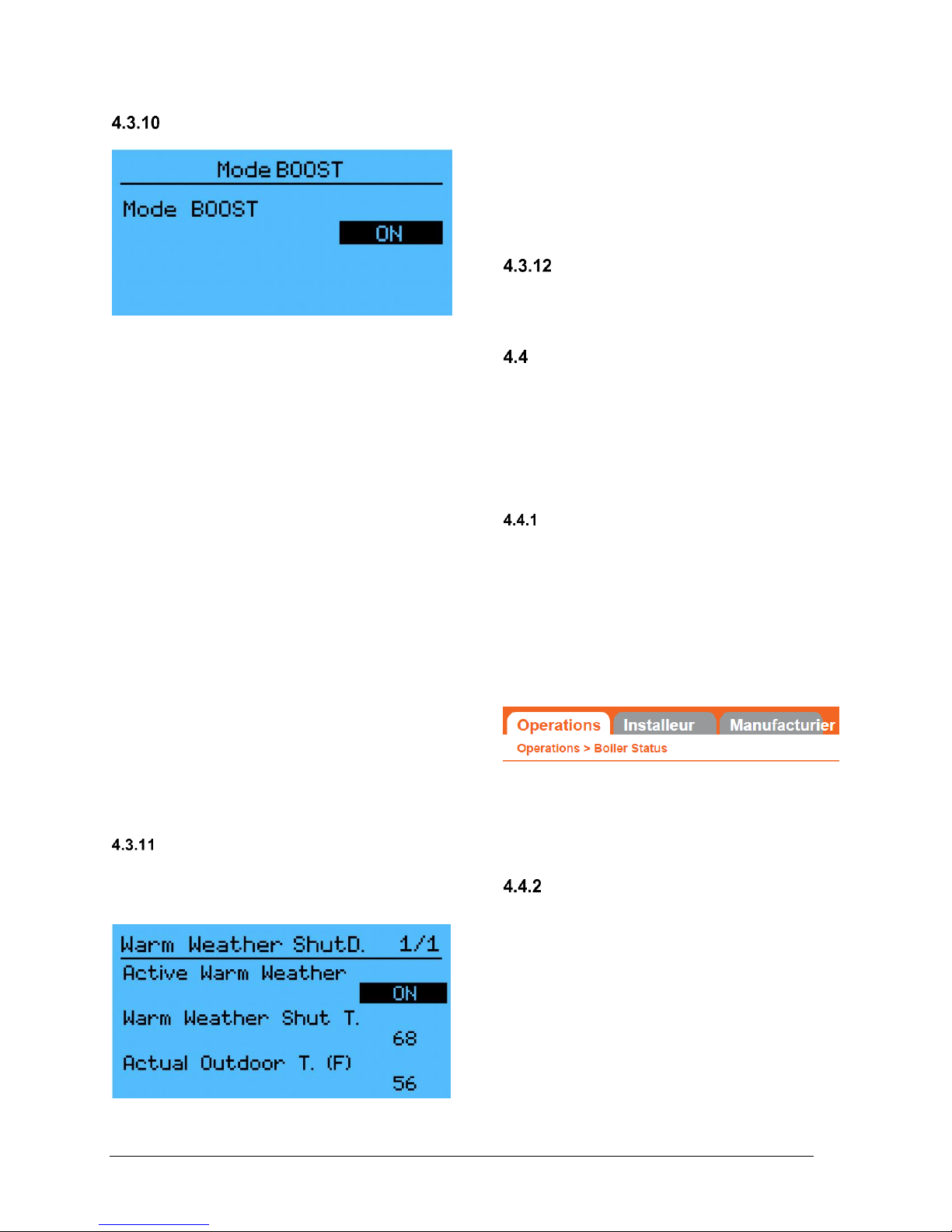
VOLTMAX ELECTRIC BOILER Installation and Operation Manual (Revised March 2019), Page 37.
BOOST MODE
Enable Boost Mode
This mode operates with the Fixed Set-point and
Outdoor reset mode.
This menu allows the Boost mode to be activated,
this mode increase the set-point temperature
when the heating load of the building exceeds the
capacity generated by the current water
temperature determined by the boiler.
This mode is activated after a period of 30 min if
the heat demand is maintained for 30 consecutive
minutes on W1. After this period, the set
temperature will start to rise until a predetermined
maximum temperature is reached depending on
the heating mode until the demand is filled. This
temperature increase is temporary and has a
maximum duration of 120 minutes or when the
request is terminated on W1.
N.B. The BOOST mode is particularly interesting
for applications such as:
o Applications with a programmable thermostat
with automatic lowering of the building
temperature.
o Return to normal heat demand after a
prolonged period of sunshine where there
have been no long-term demands and,
therefore, heating floors will take a long time
to provide heat at d Normal water.
WARM WEATHER SHUTDOWN
Shuts down the boiler when the outside
temperature reaches an established
threshold.
This mode stops the boiler’s heating production
when the outside temperature is higher than a
pre-determined temperature (ex: 68°F).
Note: If the boiler is configured with DHW mode,
it will continue to operate normally in order to
meet the DHW heating demand.
CHANGE PASSWORD
Changing the password
This menu allows you to change the installer
account password
ETHERNET
The settings available on the controller are also
available remotely on a web portal. This portal
works only when the boiler is properly connected
to an internet or Ethernet network. The various
setting parameters and the protocol for
connecting the boiler to a network are available in
the Communication menu and Section 4.3.7.
WEB PORTAL
In order to access the boiler remotely via the
internet, the boiler controller must be correctly
connected.
The web portal has 3 main menus, the User,
Installer and Manufacturer menu. The structure
of the web portal is the same as the controller;
please refer to the previous sections, if you have
any questions.
Ex: The user can obtain information concerning
the boiler status, in the menu Operations /
N.B. The password to acces the installater
section of the website is 1111.
ALARM NOTIFICATION EMAIL
In order to configure the alarm by e-mail, you
must:
1. You must first ensure that you enter the
correct information in the controller
(depending on your network) under the
following options:
a. IP address
b. Default Gateway
c. Subnet mask
d. Primary DNS
e. Secondary DNS

VOLTMAX ELECTRIC BOILER Installation and Operation Manual (Revised March 2019), Page 38.
You must restart the device for the changes to
take place.
2. Access the Boiler Web Portal.
3. Click on the Installer / Communication menu.
4. Enter your e-mail under Recipient. You can
also use your own mail server by entering the
necessary data.
5. Then select the types of alarms you want to
receive by e-mail.
If you want to send alarms to different e-mail
addresses, simply enter a list of e-mails.
The parameters to enter on the web page are
indicated on the screen shot below.
Personal Email Server (Type: Gmail)
The M171 controller does not support SSL
encryption. Thus, your SMTP Email server must
accept an unencrypted connection.
Internet service providers usually have a specific
server that accepts connections without
encryptions. On-line messaging services, such as
Hotmail, G-mail, do not accept unencrypted
communications. In order to work around the
problem, there are relay services such as
SMTP2GO: https://www.smtp2go.com, to relay
between controller communication and your
messaging system. This service is free for up to
1000 emails per month.

VOLTMAX ELECTRIC BOILER Installation and Operation Manual (Revised March 2019), Page 39.
BOILER STATUS DISPLAY SETTINGS
(Variables beginning with AV and BV are read variables, while variables beginning with "W" are editable)
Display
Description
BACnet Variable
Instance
Tag
BACnet Description
T. Set point
The set-point temperature of the boiler. The boiler
will activate its elements accordingly in order to
modulate its water outlet temperature.
AV_TBoilerSTP
53
8388661
---
T. Out Boiler
The temperature at the outlet of the VoltMax boiler.
AV_BoilerTOut
0
8388608
---
T. In Boiler
The temperature at the inlet of the VoltMax boiler.
This sensor is only available on SCR models.
AV_BoilerTIn
1
8388609
---
T. Outdoor
This variable allows the outdoor temperature to be
displayed in real time when the outdoor temperature
sensor is correctly connected.
AV_OutdoorT
2
8388610
---
Boiler
Pressure
This variable allows the reading of the pressure
sensor inside the boiler.
AV_SensorPressure
Signal
6
8388614
---
Actual power
The actual power used in kilowatt
AV_ActualPowerkw
8
8388616
---
% max
authorized
power
The maximum permissible power as a percentage of
the nominal power.
AV_CapLimitPrc
54
8388662
---
Consumption
The power consumption of the last cycle.
You must first begin a history cycle (MAIN MENU /
CONSUMPTION)
---
---
---
---
Actual
Current (A)
This variable allows the reading of the current sensor
inside the boiler.
This sensor is only available on SCR models.
Av_SensorCurrent_
Signal
6
8388614
---
Demand W1
When requesting heating on W1, allowing the
operation of the heating elements.
BV_HeatingW1
0
20971520
0 = No W1 demand
1 = W1 demand
Demand
W2/DHW
When requesting heating on W2 or DHW, allowing
the operation of the heating elements.
BV_HeatingW2
1
20971521
0 = No W2 demand
1 = W2 demand
Flow
When no heating elements are active, the
calculated flow rate will be equivalent to 0,
because the theoretical flow is calculated according
to the power used, T. Out Boiler and T. In Boiler T.
Available on SCR models only.
AV_WaterFlow
10
8388618
---
SCR
Modulation %
Percentages of the SCR relay utilisation.
(For SCR model only)
AV_ModSCR
7
8388615
Stage #1
Status of stage #1 (For STG model only)
BV_RelStage1
13
20971533
0 = Stage 1 not working

VOLTMAX ELECTRIC BOILER Installation and Operation Manual (Revised March 2019), Page 40.
1 = Operation of stage 1
Stage #2
Status of stage #2
BV_RelStage2
5
20971525
0 = Stage 2 not working
1 = Operation of stage 2
Stage #3
Status of stage #3
BV_RelStage3
6
20971526
0 = Stage 3 not working
1 = Operation of stage 3
Stage #4
Status of stage #4
BV_RelStage4
7
20971527
0 = Stage 4 not working
1 = Operation of stage 4
Stage #5
Status of stage #5
BV_RelStage5
11
20971531
0 = Stage 5 not working
1 = Operation of stage 5
Stage #6
Status of stage #6
BV_RelStage6
12
20971532
0 = Stage 6 not working
1 = Operation of stage 6
Stage #7
Status of stage #7
BV_RelStage7
41
20971561
0 = Stage 7 not working
1 = Operation of stage 7
Stage #8
Status of stage #8
BV_RelStage8
42
20971562
0 = Stage 8 not working
1 = Operation of stage 8
Alarm
HL/LWCO
Alarm
Alarm triggered because of a high limit and low
water level manual alarm.
BV_StatusAlarmHL/
LW
14
20971534
0 = Normal operation
1 = Alarm activated
HL Alarm
Alarm triggered when the boiler’s internal
temperature is higher than the threshold.
BV_AlarmIntHL
15
20971535
0 = Normal operation
1 = Alarm activated
LL Alarm
Alarm triggered by the boiler’s lack of capacity.
BV_AlarmLL
21
20971541
0 = Normal operation
1 = Alarm activated
Low
Pressure
Alarm
Alarm triggered by a low pressure.
BV_AlarmLowPress
ure
16
20971536
0 = Normal operation
1 = Alarm activated
High
Pressure
Alarm
Alarm triggered by a high pressure.
BV_AlarmHighPress
ure
17
20971537
0 = Normal operation
1 = Alarm activated
Flow Alarm
Alarm triggered by a flow problem.
BV_AlarmLowFlow
18
20971538
0 = Normal operation
1 = Alarm activated
Current
Alarm
Alarm triggered by a current problem.
BV_AlarmCurrent
19
20971539
0 = Normal operation
1 = Alarm activated
Sensor Alarm
Alarm triggered by a sensor problem.
BV_AlarmSensor
20
20971540
0 = Normal operation
1 = Alarm activated
Boiler model
The VoltMax boiler model.
---
---
Tension
The nominal voltage of the VoltMax boiler.
---
---
Firmware
version
The controller’s firmware version.
---
---

VOLTMAX ELECTRIC BOILER Installation and Operation Manual (Revised March 2019), Page 41.
Program
name
The controller’s program name and version.
---
---
HEATING MODE W1 SETTINGS
(Variables beginning with AV and BV are read variables, while variables beginning with "W" are editable)
Display
BACnet variable
Instance
Tag
Description
Parameters
Default
Head
demand W1
WP_HeatingW1
43
20971563
Allows to select W1 heating demand source.
BACnet or Local
Local
Bacnet
Local
Operating
Mode
WP_HeatingMod
eW1
11
8388619
Selects the power limitation mode between Stop,
Modulation T. Ext, DCC 0-10VDC and Fixed.
0 = Stop
1 = Outdoor Reset
2 = DCC 0-10VDC
3 = Fixed
Fixed
FIXED MODE
Configure the fixed set-point temperature
Display
BACnet Variable
Instance
Tag
Description
Selection
Default
W1 Set
point
WP_FixedSTPT
W1
22
8388630
Selects the fixed set-point temperature when there
is demand on W1.
10 to 93 0C
50 to 200 0F
140 0F
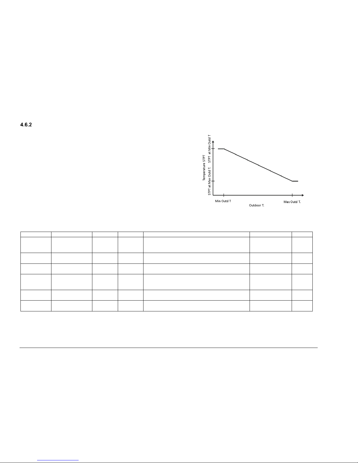
VOLTMAX ELECTRIC BOILER Installation and Operation Manual (Revised March 2019), Page 42.
OUTDOOR RESET MODE
Adjust the set-point temperature according to the outside temperature
This mode allows modulating the boiler output set-point temperature as a
function of the outdoor temperature. The outdoor temperature value comes
from a temperature sensor connected to the boiler controller.
If the outdoor sensor is not connected or if its circuit is open, an alarm signal
will be displayed on the display (SE). The boiler temperature set-point will
become the set value at STPT Min T. Outdoor.
Figure 15 : Outdoor reset curve
Table 10 : OUTDOOR RESET MODE Settings
Display
BACnet Variable
Instance
Tag
Description
Parameters
Default
Calculated
SPTP
AV_TBoilerSTPT
CalculatedOUTR
ST
12
8388625
Current set-point temperature calculated based on
the adjustment curve and the outside temperature
10 to 93 0C
50 to 200 0F
---
STPT at Min
Outd T
WP_STPTatMinO
utdT
13
8388621
Boiler set-point temperature when the outside
temperature reaches the Min Outd T.
10 to 93 0C
50 to 200 0F
140 0F
STPT at
Max Outd T
WP_STPTatMax
OutdT
14
8388622
Boiler set-point temperature when the outside
temperature reaches the Max Outd T.
10 to 93 0C
50 to 200 0F
80 0F
Outdoor T.
AV_OutdoorT
2
8388610
Displays the outside temperature in real time when
the outdoor temperature sensor is properly
connected.
-46 to 107 °C
-50 to 250 °F
---
Min Outd T.
WP_MinOutdRst
T
15
8388623
Minimum outside temperature (Set to the area’s
coldest average temperature)
-46 to 107 °C
-50 to 250 °F
-10 0F
Max Outd T.
WP_MaxOutdRst
T
16
8388624
Maximum outside temperature at which the
building will need heating
-46 to 107 °C
-50 to 250 °F
65 0F
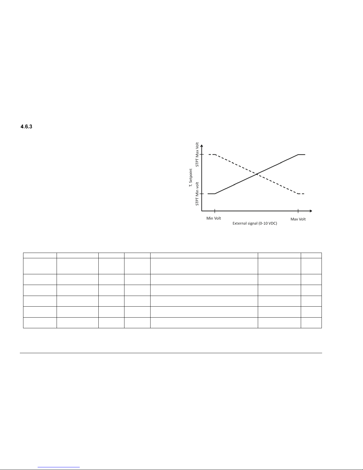
VOLTMAX ELECTRIC BOILER Installation and Operation Manual (Revised March 2019), Page 43.
MODE: DDC 0-10VDC
Modulation of the set-point temperature as a function of 0-10 VDC
(Available only on SCR model)
This operating mode allows to modulate the set-point temperature of
the water outlet of the boiler according to a 0-10VDC signal applied
to the terminal block 0-10Vdc T and 0-10Vdc G from an external
controller (Ex: An energy management software).
A heat demand (closed contact W1 and / or W2-DHW) must be
present so that the boiler can heat up.
Figure 16 : Mode DDC 0-10 VDC
Table 11 : Specific parameters in DDC 0-10 VDC
Display
BACnet variable
Instance
Tag
Description
Parameters
Default
T. STPT 010VDC
AV_TBoilerSTPT
CalculatedV
17
8388625
This variable represents the set-point temperature
based on the voltage of the building control
system.
0
C or 0F
---
STPT at Min
Volt
WP_STPTatMinR
emote010V
20
8388626
Set-point of the boiler temperature corresponding
to the voltage level of Min Voltage.
0
C or 0F
80 0F
STPT at Max
Volt
WP_STPTatMax
Remote010V
21
8388627
Set-point of the boiler temperature corresponding
to the voltage level of Max Voltage.
0
C or 0F
140 0F
Actual
voltage
AV_Remote010V
STPT
3
8388611
Voltage emitted by the external controller in real
time
0-10 V
---
Max Voltage
WP_MinRemoteV
STPT
18
8388626
The maximum voltage that the external controller
can send
0-10 V
10
Min Voltage
WP_MaxRemote
VSTPT
19
8388627
The minimum voltage that the external controller
can send
0-10 V
0

VOLTMAX ELECTRIC BOILER Installation and Operation Manual (Revised March 2019), Page 44.
W2 MODE SET-POINT TEMPERATURE SETTINGS
(Variables beginning with AV and BV are read variables, while variables beginning with "W" are editable)
Display
BACnet Variable
Instance
Tag
Description
Selection
Default
Heat
demande
W2/DHW
WP_HeatingW2
44
20971564
Allows to select W1 heating demand source.
BACnet or Local
Local
BACnet
Local
Operating
Mode
WP_HeatingMod
eW2
23
8388631
Select the boiler’s operating mode during demand
on W2 (None, W2 and DHW)
0 = W2
1 = DHW
2 = None
None
W2 MODE
Configures the fixed set-point temperature during demand on W2
Display
BACnet Variable
Instance
Tag
Description
Selection
Default
W2 Set
point
WP_FixedSTPT
W2
24
8388632
Selects the fixed set-point temperature during
demand on W2.
10 to 93 0C
50 to 200 0F
175
deg F0
DHW MODE
Configures the fixed set-point temperature during demand on DHW mode.
Display
BACnet Variable
Instance
Tag
Description
Selection
Default
T. Set-point
DHW
WP_FixedSTPT
W2
24
8388632
Selects the fixed set-point temperature during
demand on W2 terminale
10 to 93 0C
50 to 200 0F
175 0F
T. Min Boiler
WP_FixedSTPT
W0
26
8388634
Selects the boiler’s minimum temperature.
The boiler’s heating elements will activate
automatically to keep the hydronic system at the
selected temperature.
10 to 93 0C
50 to 200 0F
150 0F
POWER LIMITATION MENU SETTINGS
(Variables beginning with AV and BV are read variables, while variables beginning with "W" are editable)
You can control the boiler power with different modes. Their configuration is below.
Display
BACnet Variable
Instance
Tag
Description
Selection
Default
Limitation
Mode
WP_CapLimitMo
de
31
8388639
Select the power limitation between
None, Manual, DCC 0-10VDC,T. Ext and
Scheduled.
0 = None
1 = Manual
2 = DCC 0-10VDC
3 = T. Ext
4 = Scheduled
---

VOLTMAX ELECTRIC BOILER Installation and Operation Manual (Revised March 2019), Page 45.
MANUAL MODE
The maximum power is set manually.
Display
BACnet Variable
Instance
Tag
Description
Selection
Default
Current
authorized
max kW
WP_ManualCapL
imit
32
8388640
Configures the maximum electrical power that the
boiler will use.
0 to maximum rated
power
---
0-10 VDC MODE
An external 0-10 VDC controller is used to adjust the maximum power.
Display
BACnet Variable
Instance
Tag
Description
Selection
Default
Current
authorized
max power
(%)
AV_CapLimitPrc
54
8388662
The value of power (%) calculated based on the
current and the boiler’s nominal operating voltage
0 to maximum rated
power (%)
---
Minimum
Power Volt
(kW)
WP_MinRemote
VCapLimit
33
8388641
The boiler’s maximum power when the external
controller voltage is at Min Voltage
0 to maximum rated
power
0
Maximum
Power Volt
(kW)
WP_MaxRemote
VCapLimit
34
8388642
The boiler’s maximum power when the external
controller voltage is at V for max. cap.
0 to maximum rated
power
---
Current
Signal 010V
AV_Remote010V
Cap
4
8388612
Voltage emitted by the external controller in real
time
0-10 V
---
Min Voltage
(VDC)
WP_CapLimitatM
inRemote010V
35
8388628
The voltage representing the external controller’s
minimum set-point
0-10 V
0
Max Voltage
(VDC)
WP_CapLimitatM
axRemote010V
36
8388629
The voltage representing the external controller’s
maximum set-point
0-10
10
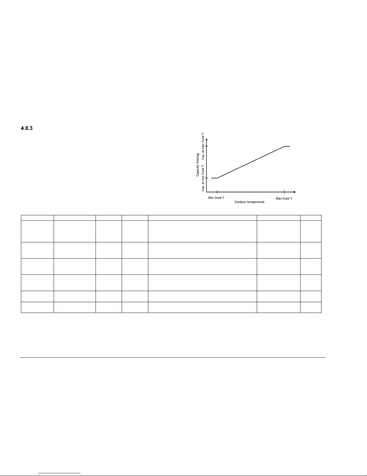
VOLTMAX ELECTRIC BOILER Installation and Operation Manual (Revised March 2019), Page 46.
T. EXT MODE
Maximum power modulation is based on the outside temperature.
Power modulation is shown below.
If the external sensor is not connected or there is a problem with
the sensor, then the power will be limited according to Cap. At T.
Ext. Min.
Figure 17: Adjustment curve according to the T. ext mode
Display
BACnet Variable
Instance
Tag
Description
Parameters
Default
Current
authorized
max power
(%)
AV_CapLimitPrc
54
8388662
The value of power (%) calculated based on the
current and the boiler’s nominal operating voltage
0 to maximum
rated power (%)
---
Cap. At T.
Ext. Min
WP_CapLimitatM
inOutdT
37
8388645
Maximum authorized capacity according to T. Ext.
Min
Ex. Maximum power is 170 kW for T. Ext min
0 to maximum
rated power
---
Cap. At T.
Ext. Max
WP_CapLimitatM
axOutdT
38
8388646
Maximum authorized capacity according to T. Ext.
Max
Ex. Maximum power is 120 kW for T. Ext min
0 to maximum
rated power
---
Actual T.
Exterior
AV_OutdoorT
2
8388610
This variable allows you to view the outside
temperature in real time when the outside
temperature sensor is properly connected.
-46 to 107 °C
-50 to 250 °F
---
T. Ext. Min
WP_MinOutdTCa
pLimit
39
8388647
Minimal outside temperature used to adjust the
maximum power
-46 to 107 °C
-50 to 250 °F
-10 F
T. Ext. Max
WP_MaxOutdTC
apLimit
40
8388647
Maximum outside temperature used to adjust the
maximum power
-46 to 107 °C
-50 to 250 °F
65 F
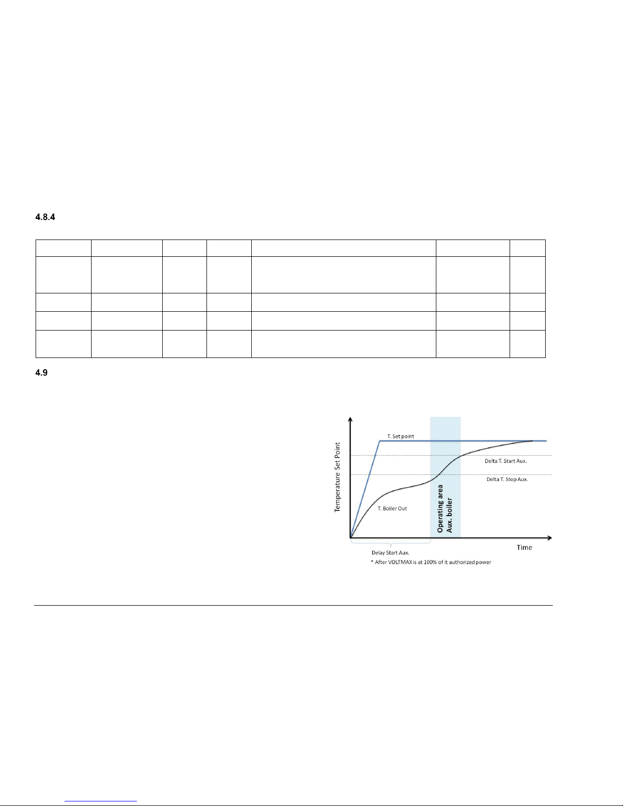
VOLTMAX ELECTRIC BOILER Installation and Operation Manual (Revised March 2019), Page 47.
SCHEDULE MODE
Power can be modulated according to a fixed schedule. This can be programmed in the Schedule Setting menu.
Display
BACnet variable
Instance
Tag
Description
Parameters
Default
Current
authorized
max power
(%)
AV_CapLimitPrc
54
8388662
The value of power (%) calculated based on the
current and the boiler’s nominal operating voltage
0 to maximum
rated power (%)
---
Cap In
Schedule
WP_CapLimitDay
Mode
41
8388649
Power limitation when the boiler internal clock is
within the power limitation schedule.
0 to maximum
rated power
---
Cap Out
Schedule
WP_CapLimitNig
htMode
42
8388650
Power limitation when the boiler internal clock is
outside the power limitation schedule.
0 to maximum
rated power
---
Schedule
---
Configuring the boiler power limitation schedule. In
order to operate correctly, you must first adjust the
internal boiler clock in the Clock Setting menu.
---
---
AUXILIARY BOILER SETTINGS
(Variables beginning with AV and BV are read variables, while variables beginning with "W" are editable)
(Only available on SCR model)
The system allows control of an auxiliary boiler to the system. The different configuration options are shown below.
In order for the boiler to start, two conditions must be met:
The water outlet temperature of the Voltmax boiler must be below the start-up
temperature Aux.
(T. Out Boiler < (T Set-point - Delta T. Aux Start)
The water outlet temperature of the Voltmax boiler must be below the start-up
temperature Aux. for a period of X minutes (Start Delay Aux), after the Voltmax
boiler is at 100% of its authorized power.
In order for the auxiliary boiler to turn off, the water outlet temperature of the
Voltmax boiler must be above the Aux.
T Out Boiler > (T. Set-point - Delta T. Aux Stop)

VOLTMAX ELECTRIC BOILER Installation and Operation Manual (Revised March 2019), Page 48.
BACKUP MODE
Configures a second boiler as a backup.
Display
BACnet variable
Instance
Tag
Description
Parameters
Default
STPT
Source
WP_STPTSource
Aux
22
20971542
Selects the source used to control the set-point
temperature.
Auxiliary means that the set-point will be
determined by the auxiliary boiler. The VoltMax
boiler therefore has no set-point temperature and is
only used to activate the auxiliary boiler relay.
Voltmax means that the set-point temperature will
be determined by the VoltMax boiler.
Auxiliary or
VoltMax
0 = Auxilliary
1 = VoltMax
VoltMax
Delta T.
Start Aux.
WP_DeltaTStartA
ux
44
8388652
This option adjusts the temperature differential (setpoint temperature – Water outlet temperature) used
to activate the auxiliary boiler.
0 to 55 0C
0 to 100 0F
20 0F
Delta T.
Stop Aux.
WP_DeltaTStopA
ux
45
8388653
This option configures the temperature differential
(set-point temperature – Water outlet temperature)
in the VoltMax boiler used to deactivate the
auxiliary boiler.
0 to 55 0C
0 to 100 0F
5 0F
Delay Start
Aux.
WP_DelayStartA
ux
46
8388654
This option adjusts the delay before activating the
auxiliary boiler.
Min
10
EXTERNAL CONTACT MODE
This mode selects the hydronic system heating source (VoltMax boiler or auxiliary boiler) using the BI-E terminal’s electrical switch.
Display
BACnet Variable
Instance
Tag
Description
Settings
Default
STPT
Source
WP_STPTSource
Aux
22
20971542
Selects the source used to control the set-point
temperature.
External means that the set-point will be
determined by the auxiliary boiler. The VoltMax
boiler therefore has no set-point temperature and is
used only to activate the auxiliary boiler’s relay.
Internal means that the set-point temperature will
be determined by the VoltMax boiler.
External or
internal
Internal
MANUAL MODE
Manual mode is used to select the system’s operating mode (Electric or auxiliary).
Display
BACnet Variable
Instance
Tag
Description
Selection
Default
Active Boiler
WP_ActiveBoiler
23
20971543
This option selects which boiler is in operation;
either the VoltMax boiler (electric) or the auxiliary
boilder (auxiliary).
VoltMax ou
Auxiliary
0 = VoltMax
VoltMax
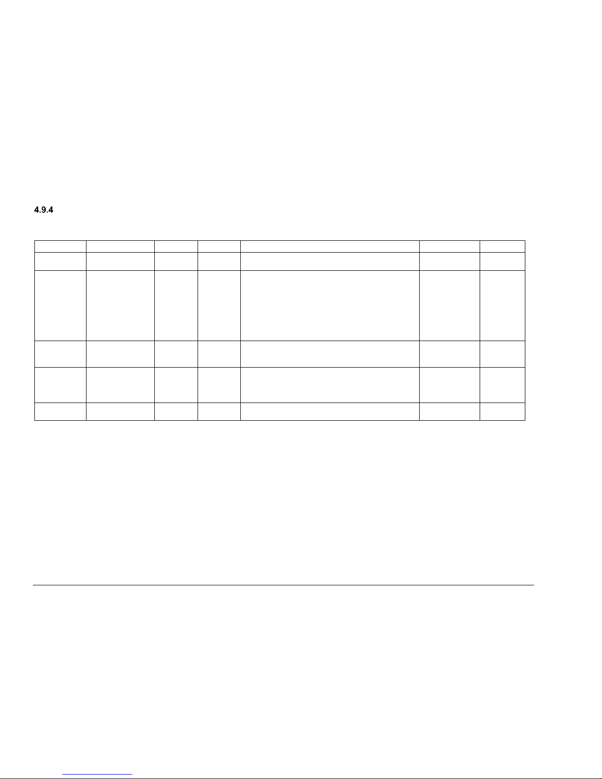
VOLTMAX ELECTRIC BOILER Installation and Operation Manual (Revised March 2019), Page 49.
BI-ENERGY MODE
This mode selects the hydronic system heating source (VoltMax boiler or auxiliary boiler) using the BI-E terminal’s electrical switch. The benefit of this
mode is that the system can operate the back-up boiler when needed.
Display
BACnet variable
Instance
Tag
Description
Parameters
Default
Bi-Energy
Source
WP_SignalBiEne
rgy
47
20971567
Allows to select Bi-energy activation contact
source. BACnet or Local
Local
BACnet
Local
STPT
Source
WP_STPTSource
Aux
22
20971542
Selects the source used to control the set-point
temperature.
Auxiliary means that the set-point will be
determined by the auxiliary boiler. The VoltMax
boiler has no set-point temperature and is only
used to activate the auxiliary boiler relay.
Voltmax means that the set-point temperature will
be determined by the VoltMax boiler.
Auxiliary or
VoltMax
0 = Auxiliary
1 = VoltMax
VoltMax
Delta T.
Start Aux.
WP_DeltaTStartA
ux
44
8388652
This option adjusts the temperature differential
(Set-point temperature – Water outlet temperature)
used to activate the auxiliary boiler.
0 to 55 0C
0 to 100 0F
20 0F
Delta T.
Stop Aux.
WP_DeltaTStopA
ux
45
8388653
This option configures the temperature differential
(Set-point temperature – Water outlet temperature)
in the VoltMax boiler used to deactivate the
auxiliary boiler.
0 to 55 0C
0 to 100 0F
5 0F
Delay Start
Aux.
WP_DelayStartA
ux
46
8388654
This option adjusts the delay in minutes before
activating the auxiliary boiler.
Min
10
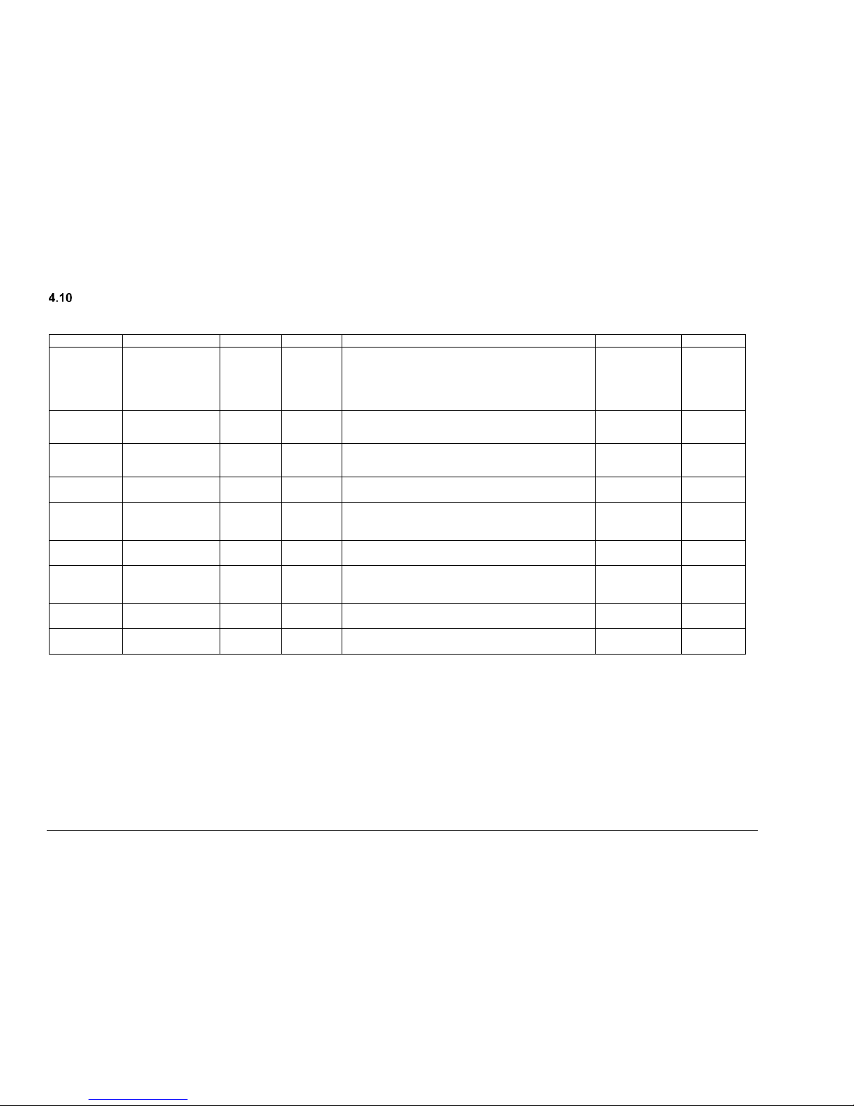
VOLTMAX ELECTRIC BOILER Installation and Operation Manual (Revised March 2019), Page 50.
LIMIT CONFIGURATION MENU SETTINGS
(Variables beginning with AV and BV are read variables, while variables beginning with "W" are editable)
Display
BACnet variable
Instance
Tag
Description
Settings
Default
High Limit T
WP_HighLimitTe
mp
47
8388655
Adjusts the temperature high limit at which the
alarm triggers. If the water temperature leaving the
boiler exceeds the alarm’s high limit, it will trigger
an HL alarm and the boiler’s heating elements will
be deactivated.
0 to 92 °C
0 to 199 °F
195 °F
Low Limit
ON/OFF
WP_Desactivate
AlarmLL
31
20971551
Desactivates the low limit detection function (see*
below)
0=OFF
1=ON
ON
Delta T. LL*
WP_DeltaTLL
48
8388656
Adjusts the temperature differential to activate the
LL alarm.
0 to -55 °C
0 to -99 °F
-20 °F
Delay LL
(min)*
WP_DelayLL
49
8388657
Adjusts the LL alarm trigger delay.
0 to 180 min
60 min
Pressure
sensor
WP_ActivatePres
sureSensor
24
20971544
Activates the boiler’s internal pressure sensor
module.
OFF / ON
0 = Off ; 1 =
On
ON
Actual
pressure
AV_SensorPress
ureSignal
6
8388614
Reads the boiler’s internal pressure sensor.
---
---
Current
sensor
WP_ActivateCurr
entSensor
25
20971545
Activates the current sensor module.
This module is available on SCR models only
OFF / ON
0 = Off ; 1 =
On
ON
Calculated
current
AV_CalculatedCu
rrentSignal
50
8388658
Used to view the VoltMax boiler’s theoretical
electric consumption current.
---
---
Actual
current
AV_SensorCurre
ntSignal
5
8388613
View current as measured by a sensor.
---
---
*The LL (low limit) function aims to identify a potential anomaly of the boiler by detecting a potential lack of power that makes the
temperature of the water at the boiler outlet to be anormaly lower than the set temperature during a predefined time period (see
section 6.2.3).
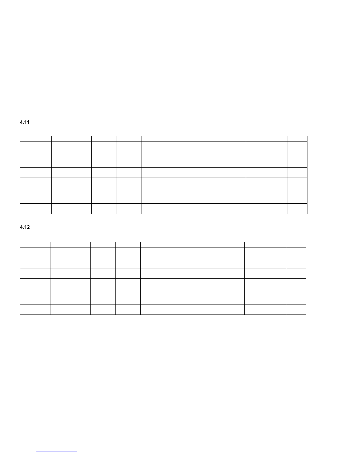
VOLTMAX ELECTRIC BOILER Installation and Operation Manual (Revised March 2019), Page 51.
CONFIG. ALARM MENU SETTINGS
(Variables beginning with AV and BV are read variables, while variables beginning with "W" are editable)
Display
BACnet Variable
Instance
Tag
Description
Settings
Default
Occupation
mode
WP_Schedule_O
n
46
20971566
Allows to select Bi-energy activation contact
source. BACnet or Local
Local
BACnet
Local
Status:
HL/LWCO
alarm
BV_StatusExtAlar
m
28
20971548
Displays the external alarm status. The external
alarm contact is activated only if a high limit or low
water level alarm occurs.
0 = Off
1 = On
---
Silence
Alarm
WP_SilenceAlar
m
27
20971547
Temporarily suspends the alarm.
0 = Off
1 = On
Off
Reset
Lockdown
WP_ResetLockD
own
29
20971549
Cancels the Lockdown mode without resetting the
unit.
Resetting the unit is required when it is in LOCK-
OUT mode, following high external temperature or
low water level alarms over a short period.
0 = Off
1 = On
Off
Internal
buzzer
WP_ActivateInter
nalBuzzer
30
20971550
Activates the controller’s internal buzzer.
0 = Off
1 = On
On
OCCUPATION MENU SETTINGS
(Variables beginning with AV and BV are read variables, while variables beginning with "W" are editable)
Display
BACnet Variable
Instance
Tag
Description
Settings
Default
Occupation
Mode
WP_ActivateOcc
upationMode
33
20971553
Activates the Occupation function.
0 = Off
1 = On
---
Source OCC
WP_SourceOccu
pation
34
20971554
Selects the source used to determine the building’s
occupation schedule.
0 = Schedule
1 = Contact OCC
Lowering T.
WP_LoweringTIn
noccupation
52
8388660
Lowers the set-point temperature.
---
Off
Occupation
Status
BV_StatusOccup
ation
35
20971555
Displays the Occupation mode status.
Off: Day mode; the set-point temperature is not
lowered
On: Night mode; the set-point temperature is
lowered according to the configuration
0 = Off
1 = On
On
Force Day
Mode
WP_ForceOccup
ationDay
36
20971556
Forces the Day mode. The set-point temperature
will not be lowered.
0 = Off ; 1 = On
Off

VOLTMAX ELECTRIC BOILER Installation and Operation Manual (Revised March 2019), Page 52.
BOOST MENU SETTINGS
(Variables beginning with AV and BV are read variables, while variables beginning with "W" are editable)
Display
BACnet Variable
Instance
Tag
Description
Settings
Default
Mode
BOOST
WP_ActivateMod
eBoost
37
20971557
This option enables the BOOST functionality.
0 = Off
1 = On
Off
WARM WEATHER SHUTDOWN MENU SETTINGS
(Variables beginning with AV and BV are read variables, while variables beginning with "W" are editable)
Display
BACnet Variable
Instance
Tag
Description
Settings
Default
Warm
Weather
Shutdown
WP_ActivateWar
mWeatherSD
26
20971546
Shuts down the boiler when the outside
temperature reaches a specific temperature. This
temperature can be set in the Warm Weather
Shutdown Temperature box.
OFF / ON
0 = Off ; 1 = On
OFF
T. Ext
Shutdown
WWSD
WP_WarmWeath
erSDTemp
51
8388659
Sets the outside temperature that activates the
Warm Weather Shutdown, if it shuts down the
boiler.
0 to 55 °C
0 to 99 °F
68 °F
Current Ext.
T.
AV_OutdoorT
2
8388610
Shows the outside temperature in real time.
-46 to 107 °C
-50 to 250 °F
---

VOLTMAX ELECTRIC BOILER Installation and Operation Manual (Revised March 2019), Page 53.
BOILER START UP
Before operating this boiler, be sure to read and follow these instructions, as well as the
warnings printed in this manual. Failure to do so can result in unsafe operation of the boiler
resulting in property damage, bodily injury, or death. Should you have any problems reading,
following or difficulty in understanding the instructions in this manual, STOP, and get help
from a qualified person.
Do not turn on the boiler unless it is filled with water. Do not turn on the boiler if the cold-water
supply shut-off valve is closed.
After the boiler, has been plumbed and wired, it is
now ready to be set for automatic operation
STARTUP PREPARATION
Remove the lid of the boiler and install the
temperature probe which is hanging outside the
control pannel with a red label indicating the
message “important “.
This sensor is used to provide the outpout water
temperature to the boiler controller. Therefore, it
shall be installed in one of the two immersion
wells indicated below. Insert in the immersion well
located on the same side of the selected water
outpout connection.
Open the service valves at the outlet of the boiler
and the cold-water supply valve (fill or makeup
water valve) to boiler.
Open the relief valve on top of the boiler in order
to purge the air out of the boiler tank during the fill
process
Leave all shutoff valves open.
Check system for leaks and repair. Purge air from
all the heating distribution zones.
Bleed air from different areas of the heat
distribution system.
Check boiler pressure gage reading. The
indicated pressure should be lower than the
pressure relief valve design rating.
ADJUSTEMENT OF THE
CONTROLLER OPERATING
PARAMETERS
After the system has been manually purged of air,
and all components (valves, vents, and
controllers) have been set properly, the boiler can
be started.
Never operate this boiler until this has been
done.
1) Make sure that there is no heat demand or
startup authorisation on W1 and W2
contactors and that the ON/OFF switch on
the left side of the panel is at OFF.
2) Turn on the boiler alimentation circuit and the
disconnect switch (option).
3) Turn on the boiler ON/OFF switch. You
should hear the mains contactors engaging
and see the controller screen turn on. The
heating elements shall not come on as long
as there is no W1 or W2 heat demand.
4) Enter the appropriate parameters in the
controller to obtain a proper operation of the
heating system on wich to boiler is installed.
The acces the menu, press “OK”, then select
“BOILER SETTING” and entre the password
“1111”. Consult section four of this manual to
adjust the paramaters.
5) Make sure that the high limit parameters of
the boiler are set at the appropriate values for
the application.
6) The high limit adjustment is possible trough
the “LIMIT setting” menu and should be
adjusted 10 to 15°F above the maximum
WARNING
!

VOLTMAX ELECTRIC BOILER Installation and Operation Manual (Revised March 2019), Page 54.
operation temperature selected. Proceed to
the adjustment of the mechanical high limit
control localized on the right in the low
voltage electric compartiment. It shall be
adjusted 10 to 15F higher than the controller
high limit.
STARTUP PROCEDURE
Before starting the boiler, make sure that the
heating distribution design is made so that the
heating elements will come on only when water is
circulating in the boiler.
1) Apply a heat demand. If the boiler target
temperature is higher than the boiler water
temperature, the heating elements shall
come on in sequence more or less rapidly
depending on the differential between the
values. If the value indicated is “---“ it is
because the authorization or start up signal is
not established.
2) When the boiler capacity has reached 100%
as displayed on the controller, measure the
amperage and voltage values drawn by the
unit. These values shall be close to those
shown on the boiler name plate.
3) Slow down the heat demand from the heating
system. The boiler temperature shall
gradually increase and the boiler capacity
shall drop gradually and stabilize when the
boiler temperature will reach a temperature
near the target temperature.
4) When the heating request is completed, the
circulating pump can continue to operate
(depending on the operating mode or the
purge time) or switch off. The heating
elements stop working.
5) Check the operation of the adjustable highlimit mechanical control
6) Check the operation of the Low Water Cut
OFF by pressing its test button during 5 sec.
The button is located on the left side of the
control panel

VOLTMAX ELECTRIC BOILER Installation and Operation Manual (Revised March 2019), Page 55.
TROUBLESHOOTING
The troubleshooting section shows the various
error messages that can occur during abnormal
operation of the boiler. It is possible to change
the limits of some alarms on the controller in the
Limit Setting.
Alarm menue Symbols
An alarm is active
The boiler is in lock mode
HL
The high limit temperature has been
reached
LL
Low limit (Lack of capacity)
P
Pressure problem alarm
A
Electrical problem alarm
F
Flow problem alarm
Se
Sensor problem alarm
The internal clock battery level is low
WARNING LIGHTS
The LEDs above the navigation buttons indicate
3 different boiler states.
Active
warning
light
Boiler status
Green
Normal operation of the boiler
Yellow
One or more alarms are active.
These alarms do not prevent the
operation of the boiler; the boiler
continues to operate in normal
mode.
Ex. The controller detects a problem
with the amperage reading sensor.
Red
A critical alarm is active,
accompanied by the buzzer (if
active).
Ex. A high limit alarm is active
OPERATING PROBLEM
IDENTIFICATION
An alarm log is available in the BOILER CONFIG
/ ALARM / ALARM LOG. Each alarm is recorded
with its alarm code, the time and date. The
register can record up to 30 alarms.
EXTERNAL HL / LWCO
When this alarm is present, the indicator light to
the left of the boiler lights red.
This alarm happens when one of the following
contacts is open: the adjustable mechanical high
limit, the manual reset high limit located in the
heating elements compartiment, a low level of
water or an external contact connected to “EXT.
HL” terminals.
The external alarm contact (SCR models only)
will be activated immediately if it has been
activated (Ext. Alarm Contact) in the Alarm
menu. The heating elements will stop working
and will start again when the water level or the
other condition returns to normal. If this alarm
happens 3 times in 1 hour or for 60 consecutives
minutes, the boiler will be set in Lock out mode.
SENSOR (SE)
The Sensor alarm indicates that a courant,
pressure or temperature sensor is defective. This
alarm will also be triggered if the external
temperature is not connected and an operating
condition require this sensor. Generaly the alarm
is coupled with the lettes A, P and F wich
indicates the defective sensor. This condition
does not turn off the boiler (except in the case of
a defective water outlet temperature sensor). The
yellow indicator light stays on as long as the
alarm condition is active.
See Table 13 for comparison of Resistance
measurements against temperature for the
outdoor sensor.
LOW LIMIT (LL)
The LL alarm is activated when the temperature
differential between the set-point temperature
and the boiler output temperature is higher than
Delta T.LL and this period is higher than the LL
delay.
The heating elements remain in operation. The
screen will automatically return to its normal state
when the temperature of the boiler approaches
the set temperature.

VOLTMAX ELECTRIC BOILER Installation and Operation Manual (Revised March 2019), Page 56.
This function can detect a possible lack of power
from the boiler and therefore possible anomalies
of certain componants. This function is generaly
not activated when the power limitation function
of the boiler is activated.
FLOW (F)
(Available only on SCR model)
The flow alarm is triggered when the theoretical
flow calculated from the water input and output
temperature differential (max.50F) is above the
authorized flow limit.
This condition triggered by a lack of flow does not
turn off the boiler but activates a yellow indicator
light as long as the condition is active.
CURRENT (A)
The Current alarm is triggered when there is a
difference of more than 20% between the
measured current and the calculated theoretical
current. This may indicate an electrical problem
from a wrong connection.
This condition triggered by a lack of flow does not
turn off the boiler but activates a yellow indicator
light as long as the condition is active. If more
than 50% of the stages are detected as defective,
the alarm will then shut down the boiler and the
red light will light up.
HL TEMPERATURE (HL)
The outlet temperature of the boiler is above the
high limit allowed. This alarm triggers the
deactivation of the heating elements of the boiler.
The boiler is restarted when the temperature
drops below the high limit (and the set-point)
If the boiler is in this alarm state for more than 60
minutes or the condition occurs 3 times in an
hour, the boiler switches to Lock Out mode.
LOW PRESSURE (P)
The Low-Pressure alarm “P” is activated when
the pressure inside the boiler is below the allowed
limit (default: 5 psi).
This condition triggered by a lack of flow does not
turn off the boiler but activates a yellow indicator
light as long as the condition is active.
HIGH PRESSURE (P)
The High-Pressure alarm is activated when the
pressure inside the boiler is above the allowed
limit (depending on the maximum boiler pressure)
BATTERY LOW LEVEL
The low-level battery alarm appears when the
battery used by the internal clock is at a low level.
The battery needs to be replaced. To get the
replacement procedure, contact our technical
service.
LOCK OUT
Lock out mode is activated after 3 major alarms
(red indicator light) have been activated within
one hour or when a major alarm (high limit output
water temperature detected by the external
temperature sensor or low water level condition)
is maintained activated during the same time
period. When the lock mode is activated, the
boiler is deactivated and can only be restarted by
restarting the boiler (to the left of the control
panel) or by using the reset Lock Out function (in
the alarm setting menu). The details of this menu
can be found in section 4.12.
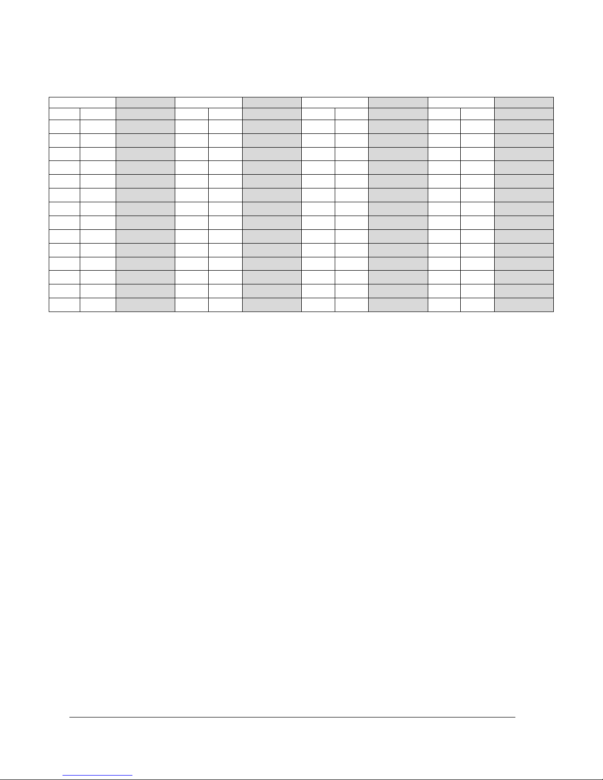
VOLTMAX ELECTRIC BOILER Installation and Operation Manual (Revised March 2019), Page 57.
Tableau 12 : Resistance (Ohm) according to the outdoor sensor measuring temperature
Temperature
Resistance
Temperature
Resistance
Temperature
Resistance
Temperature
Resistance
°F
°C Ω °F
°C Ω °F
°C Ω °F
°C
Ω
-50
-46
490 813
20
-7
46 218
90
32
7 334
160
71
1 689
-45
-43
405 710
25
-4
39 913
95
35
6 532
165
74
1 538
-40
-40
336 606
30
-1
34 558
100
38
5 828
170
77
1 403
-35
-37
280 279
35 2 29 996
105
41
5 210
175
79
1 281
-30
-34
234 196
40 4 26 099
110
43
4 665
180
82
1 172
-25
-32
196 358
45 7 22 763
115
46
4 184
185
85
1 073
-20
-29
165 180
50
10
19 900
120
49
3 760
190
88
983
-15
-26
139 402
55
13
17 436
125
52
3 383
195
91
903
-10
-23
118 018
60
16
15 311
130
54
3 050
200
93
829
-5
-21
100 221
65
18
13 474
135
57
2 754
205
96
763
0
-18
85 362
70
21
11 883
140
60
2 490
210
99
703
5
-15
72 918
75
24
10 501
145
63
2 255
215
102
648
10
-12
62 465
80
27
9 299
150
66
2 045
220
104
598
15
-9
53 658
85
29
8 250
155
68
1 857
225
107
553

VOLTMAX ELECTRIC BOILER Installation and Operation Manual (Revised March 2019), Page 58.
FUSES
Delay fuses with the same capacity and voltage
must be used when remplacing all of the boiler
fuses except for the power fuses that are “fast
acting” type T.
CONTACTOR
If one or more contactor must be replaced, make
sure that the terminal screws are well tightened
to avoid an overcharge. The required torque is
indicated on the contactor label. A verification of
the screw torque should be made annually
particuliary on the first years of service.
HEATING ELEMENTS
If a heating element must be replaced, make sure
that the replacement has identical power and
voltage as the old one. The model number and
technical caracteristics are indicated on the side
of the mounting flange of the element.
The sealing gasket must also be replaced by an
identical model as the one procured by Thermo
2000.
The torque for the bolts retaining the flange
should be 6lb.ft.
If the elements have been in contact with water or
a very humid environnement, dry then completely
before putting then under voltage. Verify the state
of the electrical isolation of the element and the
ground with a “Megger” test.
If elements are blown at their extrimites, make
sure there is no sediment deposits in the tank
befor installing new elements. If deposites are
present. A Sieve or other accessorie preventing
sediment deposits shall be installed.
TEMPERATURE SENSOR
Water outlet sensor:
The sensor is located in an immersion well
located in the heating elements compartiment on
the top of the boiler (illustration 5.1) and the
resistance vs temperature value is indicated in
table 12 above.
Water intake sensor (on SCR models only):
The sensor is located in an immersion well in the
back and at the bottom of the boiler. To acces it,
remove the plastic plug located right above the
drain valve.
EXTERNAL HIGH LIMIT CONTROL
Fix high limit control with manual arming
It is located in the heating elements compartiment
and fixed in place by a metal plate fixed to one of
the element’s flange.
During the installation one must make sure that
the surface of contact is clean and that the control
is firmly locked in place.
Adjustable high limit automatic control
It is located on the right in the control
compartiment of the boiler.
It must always be adjusted at 10°F above the high
limit temperature indicated in the operation
parameter of the controller.
INTERNAL CLOCK
If the internal clock is used and it does not keep
its reading (goes back de 0:00), the battery on the
electronic controller needs to be changed.
Contact thermo 2000 technical support for the
battery replacement procedure.

VOLTMAX ELECTRIC BOILER Installation and Operation Manual (Revised March 2019), Page 59.
MAINTENANCE
Properly maintained, your boiler will provide years of dependable, trouble free service. It is recommended that a
regular routine maintenance program be established and followed by the user. Components are subject to
eventual failure that requires service. Failure to use the correct procedures or parts in these circumstances may
make the unit unsafe or reduce the life of the boiler.
The owner should have the following inspection and maintenance procedures performed:
BOILER WATER PIPING
VISUAL INSPECTION
Check all piping for signs of leakage near joints,
unions and shut-off valves. Repair without delai to
avoid new water to enter the closed circuit and
cause corrosion.
PRESSURE RELIEF VALVE
TWICE A YEAR
Check for possible leak at the outlet of the safety
relief valve. If a leak is detected and the pressure at
the indicator is less than 28psi, change the safety
relief valve with a new one having similar
characteristics. If the pressure is higher than 28psi,
ask your heating service agency to determine the
cause of the high pressure and have it corrected
rapidly. Do not plug the outlet of this valve if a
dripping condition occurs.
AIR PURGE
TWICE A YEAR
Check for proper operation of the automatic air
purgers and activate manual air vents to eliminate
air present.
ELECTRICAL INSPECTION
ANNUALLY
It is recommended to perform a visual inspection of
the boiler electric compartment annually, during the
heating season, to ensure it is watertight and that
there are no signs of component or wiring
overheating. Repair as soon as possible if
necessary. Defective components should always be
replaced with the Original Manufacturer’s parts.
The inspection should also include a verification of
the torque of all the terminals screws and
particuliary the power contactors. The inspection
should follow with a verification of the main
temperature controls in operation as well as an
amperage and voltage reading to verify the proper
operation of all the heating elements.
The manufacturer's warranty DOES NOT cover a
tank breakage caused by improper installation
or maintenance. If the boiler safety valve opens
periodically, this may be caused by the
expansion tank.
Immediately call a qualified technician to inspect
and remedy the problem.
NOTE: To prevent premature tank failure, the air
trapped inside the system must be purged
periodically.
Before manually operating the relief valve, make
certain no one will be sprayed with the hot water
released by its opening. The water may be hot
enough to create a SCALD hazard. The water
released should be directed to a suitable drain
to prevent injury or damage.
DANGER
!
WARNING
!

VOLTMAX ELECTRIC BOILER Installation and Operation Manual (Revised March 2019), Page 60.
VoltMax LIMITED WARRANTY
Warranty Coverage for residential Installation
Thermo 2000 Inc. hereby warrants that the VoltMax tank installed in a
normal residential service shall be exempt of any leak for ten (10) years
from the purchase date. The warranty is effective as long as the original
residential purchaser owns the home in wich the unit was originaly installed.
Residential setting shall mean usage in a single-family dwelling in which the
consumer resides on a permanent basis. Also, residential setting shall mean
use in multiple family dwellings in which one (1) VoltMax boiler is to be use
in only one (1) dwelling. In the event that a leak should develop and occur
within this limited warranty period due to defective material or workmanship,
such leak having been verified by an authorized company representative,
Thermo 2000 Inc. will repair or replace at our sole option the failed unit with
the nearest comparable model at the time of replacement.
The residential owner is responsible for all costs associated with the
removal and reinstallation, shipping and handling to and from Manufacturer.
The replacement unit will be warranted for the remaining portion of the
original Warranty.
Warranty Coverage for Commercial Installation
Thermo 2000 Inc. warrants to the original purchaser that the VoltMax tank
installed in a commercial setting shall be exempt of any leak for ten (10)
years from the purchase date. Commercial setting shall mean use in other
than residential setting stated above in the residential setting definition. In
the event that a leak should develop and occur within this limited warranty
period due to defective material or workmanship, such leak having been
verified by an authorized company representative, Thermo 2000 Inc. will
repair or replace at our sole option the failed unit with the nearest
comparable model at the time of replacement.
The original purchaser is responsible for all costs associated with the
removal and reinstallation, shipping and handling to and from Manufacturer.
The replacement unit will be warranted for the remaining portion of the
original Warranty.
Limited two-year warranty on all VoltMax
components & parts
All other VoltMax components & parts are warranted for a period of two (2)
years against defects due to defective material or workmanship. The original
purchaser is responsible for all costs associated with the removal and
reinstallation, shipping and handling to and from Manufacturer. The
components, repaired or replaced are warranted for the residual period of
the initial warranty on the unit.
Limitations
Thermo 2000 shall not be responsible for any damage, loss, and
inconvenience of any nature whatsoever, directly or indirectly, relating to the
breakdown or malfunction of the unit. This warranty limits its beneficiary’s
rights. Nevertheless, the beneficiary may have other rights, which vary from
state to state.
This warranty replaces any other expressed or implicit warranty and
constitutes the sole obligation of Thermo 2000 towards the consumer. The
warranty does not cover cost of removal, reinstallation or shipping to repair
or replace the unit, nor administration fees incurred by the original consumer
purchaser.
Thermo 2000 reserves its rights to make changes in the details of design,
construction, or material, as shall in its judgment constitute an improvement
of former practices.
This warranty is valid only for installations made within the territorial limits
of Canada and the United States.
Warranty service procedure
Only authorized VoltMax retailers may handle warranty claims. The owner
or contractor must provide the defective equipment or components to
Thermo 2000 with the following details: the model, the serial number, a copy
of the original invoice and the owner identification certificate.
Exclusions
This warranty is void and shall not apply if:
A) Defects or malfunctions resulting from installation, repair,
maintenance and/or usage that are not done in conformity with the
manufacturer’s installation manual; or
B) Defects or malfunctions resulting from installation, maintenance, or
repair that are not done in accordance with regulations in force; or
C) Defects or malfunctions resulting from improper installation,
maintenance or repair done carelessly or resulting from consumer
damage (improper maintenance, misuse, abuse, accident or
alteration); or
D) Installation in which a relief valve (pressure) is not installed or if it is
not functioning properly, or when it is not connected to a drain to avoid
damage to the property; or
E) Installation in which liquid circulating in the tank does not remain in
closed circuit or installation in which piping is leaking; or
F) A polybutylene pipe or radiant panel installation without an oxygen
absorption barrier is used; or
G) Installation where the acidity of water is not within the normal
Environmental Protection Agency (EPA) (between pH 6.5 – 8.5)
guidelines or the water contains abnormal levels of particulate matter
or water exceeding 10.5 gpg; or
H) Element failure due to low water level, sediment accumulation in the
tank or by anormally high deposits at the surface of the elements; or
I) The VoltMax unit is being subject to non-authorized modifications; or
J) Defects or malfunction resulting of storing or handling done elsewhere
than Thermo 2000’s manufacturing plant; or
K) Units on which the serial number is removed or obliterated.
THERMO 2OOO INC.
500, 9
ième
Avenue, Richmond (Qc) Canada J0B 2H0
Tel: (819) 826-5613 Fax: (819) 826-6370
www.thermo2000.com
 Loading...