

THERMO 2000 TURBOMAX 44, TURBOMAX 65, TURBOMAX 34, TURBOMAX 109A, TURBOMAX 33 Use & Care Manual
...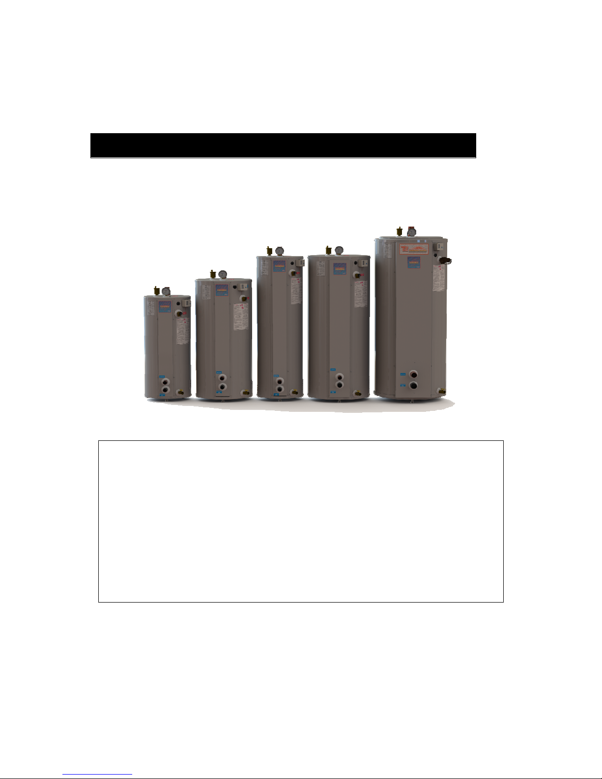
TURBOMAX
®
Instantaneous Indirect Water Heater
USE & CARE MANUAL
WITH INSTALLATION INSTRUCTIONS FOR THE CONTRACTOR
Your TURBOMAX® Instantaneous Indirect Water Heater has been carefully assembled and
factory tested to provide years of trouble-free service. In order to insure the service intended,
the following information is provided to enable proper installation, operation, safety
precautions and maintenance of this product.
It is imperative that all persons who are expected to install, operate or adjust this water heater
read the instructions carefully so that they may understand how to do so.
Any questions regarding the operation, maintenance, service or warranty of this water heater
should be directed to the entity from whom it was purchased.
When all installation steps have been completed, replace this installation manual in its original
envelope, and keep in a safe place for future reference.
Note: Copyright 2005. Thermo 2000 Inc. All rights reserved. Turbomax® is a registered trademark of Thermo 2000 Inc.
Thermo 2000 reserves the right to modify at any time and without notice colors, components, materials, specifications or
model described in or shown in this document.
Revision : July 2014
THERMO 2000 INC.
TURBOMAX Use and Care Manual with Installation Instructions July 2014 Page 2
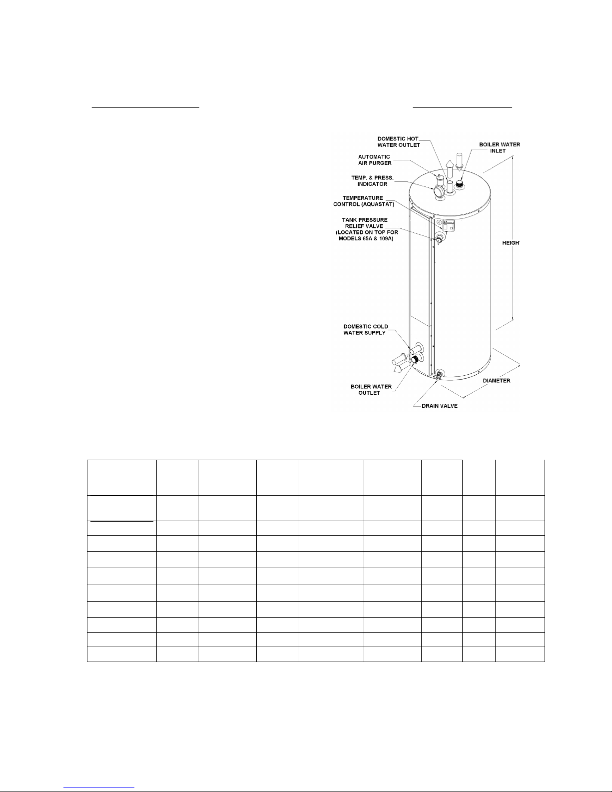
TURBOMAX® Specifications
The Turbomax indirect water has an internal copper domestic
heat exchanger made of multiple helical copper tubes
operating in parallel with a 150 psi.(200psi on ASME models
109A) maximum operating pressure rating.
All copper
components and assembly meet the low lead
requirements for potable plumbing products and adhere
to the NSF 61 standard (International Standard Drinking
Water Systems Components Health Effects
. The hot
water heater has a patented steel injector through which the
boiler water fluid enters the top side of the tank and a steel
collector through which the boiler water fluid exits at the bottom
of the tank. The tank is be made of high grade carbon steel.
All the steel joints are welded by the MIG/Argon gas process. It
has a maximum operating pressure of 150psi (200psi on
ASME model 109A). The tank is wrapped with a fiberglass
insulation jacket limiting the tank heat loss to less than ½°F per
hour. The outer steel jacket is painted with baked epoxy. The
water heater has a temperature controller (aquastat) that
makes contact when the temperature falls below the tank water
temperature set point minus an adjustable differential (10 to
40F)and breaks contact when the temperature rises over the
set point (95 to 195F). The tank has a ¾” drain ball valve
made of brass, which have a maximum working pressure of
200 psi. 3 adjustable feet support the water heater for leveling.
The hot water heater is shipped from the factory with an ASME
rated pressure relief valve set at 30psi (50 psi. on model 109 ,
65A&109A), a temperature & pressure gage (except #23, 33)
and an automatic air vent. The water heater is backed by a 15year warranty on residential applications and 10 years on
commercial applications (consult the terms of the warranty
included at the end of this manual).
SPECIFICATION
Model
Tank
Volume
Heat transfer
area (sq. ft.)
Max.
DHW
flow *
Utility
connection
Boiler
connection
Height
Diameter
Shipping
weight
TURBOMAX® 109
119usgal
.
58.9 ft² 27usgpm 2’’ Sweat M 2’’ NPT M 74’’ 29’’ 555 lbs
T
URBOMAX109A
110usgal 58.9 pi² 27usgpm 2-1/2’ Sweat M 2’’-NPT M 74’’ 29’’ 755 lbs
TURBOMAX® 65
72 usgal. 32.7 ft² 15usgpm 1-1/2’ Sweat M 1-1/2’’ NPT M 67’’ 24’’ 250 lbs
TURBOMAX 65A 67usgal 32.7 pi² 15usgpm 2’ Sweat M 1-1/2’’ NPT M 67’’ 24’’ 425 lbs
TURBOMAX® 45
48 usgal. 32.7 ft² 15usgpm 1-1/2’’ Sweat M 1-1/4’’ NPT M 55’’ 22’’ 235 lbs
TURBOMAX® 44
48 usgal. 26.2 ft² 12usgpm 1-1/2’’ Sweat M 1-1/4’’ NPT M 55’’ 22’’ 210 lbs
TURBOMAX® 34
36 usgal. 26.2 ft² 12usgpm 1-1/2’’ Sweat M 1-1/4’’ NPT M 65“ 18“ 195 lbs
TURBOMAX® 33
36 usgal. 19.6 ft² 9usgpm 1-1/4’’ Sweat M 1-1/4’’ NPT M 65“ 18“ 170 lbs
TURBOMAX® 24
26 usgal. 26.2 ft² 12usgpm 1-1/2’’ Sweat M 1-1/4’’ NPT M 49’’ 18’’ 175 lbs
TURBOMAX 23 26usgal 19.6 ft2 9usgpm 1-1/4” Sweat M 1-1/4” NPT M 49’’ 18’’ 150 lbs
*Occasional operation at higher gpm is acceptable but must be reduced on application where constant hi flow is required .
TURBOMAX Use and Care Manual with Installation Instructions July 2014 Page 3
General Safety Precautions
Be sure to read and understand the entire Use & Care Manual before attempting to install
or operate this water heater. Pay particular attention to the following General Safety
Precautions. Failure to follow these warnings could cause property damage, bodily injury or
death. Should you have any problems understanding the instructions in this manual, STOP,
and get help from a qualified installer or technician.
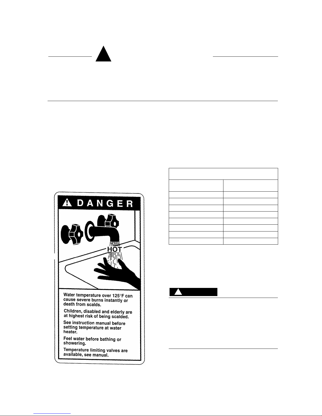
To meet commercial water use needs, the
aquastat on this water heater is adjustable up to
195°F. However water temperatures over 125°F
can cause severe burns instantly or death from
scalds. 125°F is the preferred starting point for
setting the control to supply general-purpose hot
water.
Safety and energy conservation are factors to be
considered when setting the water temperature
on the aquastat. The most energy efficient
operation will result when the temperature
setting is the lowest that satisfied the needs
consistent with the application.
Maximum water temperature occurs just after
burner or the energy source has shut off. To find
hot water temperature being delivered, turn on a
hot water faucet and place a thermometer in the
hot water stream and read the thermometer.
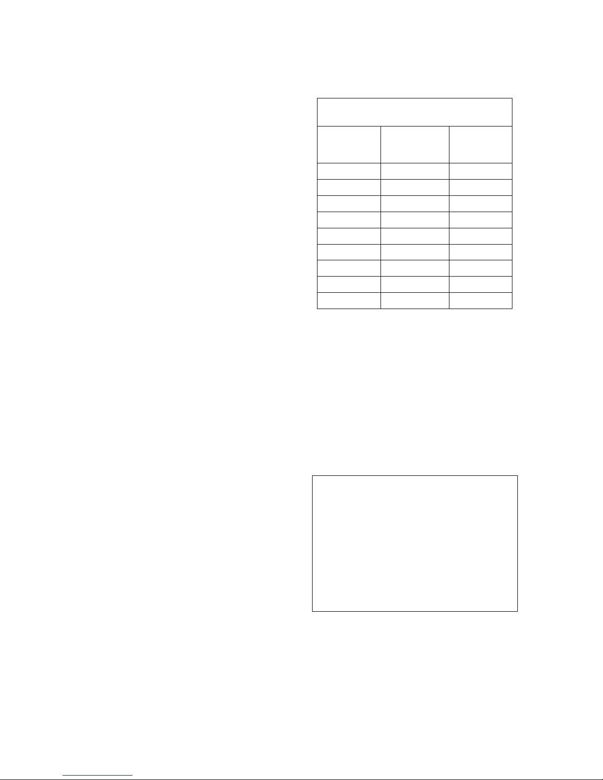
The following chart details the relationship of
water temperature and time with regard to scald
injury and may be used as a guide in determining
the safest water temperature for your applications.
TIME VS TEMPERATURE
RELATIONSHIPS IN SCALDS
Temperature
Time to Produce Serious
Burn
120°F More than 5 minutes
125°F 1-1/2 to 2 minutes
130°F About 30 seconds
135°F About 10 Seconds
140°F Less than 5 seconds
145°F Less than 3 seconds
150°F About 1-1/2 seconds
155°F About 1 second
Table courtesy of Shriners Burn Institute
The temperature of the water in the heater can be
regulated by setting the temperature dial in front of
the aquastat. To comply with safety regulations
the aquastat was set at its lowest setting before
water heater was shipped from the factory.
There is a Hot Water Scald Potential if the
aquastat is set too high. When this water
heater is supplying general purpose hot water
requirements for use by individuals, a
thermostatically controlled mixing valve for
reducing point-of-use water temperature is
recommended to reduce the risk of scald
injury. Contact a licensed plumber or local
plumbing authority for further information.
DANGER
!
!

TURBOMAX Use and Care Manual with Installation Instructions July 2014 Page 4
Introduction
The important safeguards and instructions
appearing in this manual are not meant to
cover all possible conditions and situations
that may occur. It should be understood that
common sense, caution and care are factors,
which cannot be built into every product.
These factors must be supplied by the
person(s) caring for and operating the unit.
LOCAL INSTALLATION REGULATIONS
This water heater must be installed in
accordance with these instructions and must
conform to local, or in the absence of local
codes, with the current edition of the National
Plumbing Code and the National Electric Code.
In any case where instructions in this manual
differ from local or national codes, the local or
national codes take precedence.
DECISIONS REQUIRED BEFORE
INSTALLATION
The tank of the Turbomax water heater (boiler
water) is factory shipped with a 30psi (207kPa)
pressure relief valve except on models109,
65ASME and 109ASME where it is factory set at
50psi (344kPa). If the water application requires
a higher operating pressure on the tank and If
local jurisdictions permit it, this valve can be
change by a higher pressure rated valve (max
150psi or 200psi on ASME models). But, on an
installation used to provide hot water for
domestic use, the tank pressure must always
remain lower than the pressure of the domestic
water supply specially on applications where a
potentially toxic heat transfer solution is used
inside the Turbomax tank
In some jurisdictions the boiler’s operating
pressure must be limited to 30 psi (207 kPa) by
a safety relief valve. When a higher operating
pressure level is needed, select a boiler which is
certified to operate at the required pressure.
The boiler’s output rating must be within the
heater’s recommended sizing guide
specifications. Too high an output rating may
cause a boiler short cycling condition.
Where the boiler’s output is used to supply
space heating and domestic water heating, two
options are available when wiring the controls.
The first option uses a priority relay. When the
aquastat of the water heater calls for heat, the
relay shuts off the space heating zones, giving
priority to producing domestic hot water. Any
demand for space heating is postponed until the
water heater has reached a preset level. This
delay in supplying the space heating zones is
usually not noticed by those occupying the living
space. The water heater gets adequate hot
water flow from the boiler to maintain the full
rated delivery of domestic hot water.
In the second option, the water heater will be
supplied as just another heating zone. This
means that if all space heating zones call for hot
boiler water at the same time, the water heater
may not be supplied with enough hot boiler
water to “recover” adequately. The delivery of
domestic hot water will be diminished. This is
not a problem when the boiler output is sized
adequately for both loads.
The flow of hot boiler water to the water heater
can be controlled with either a pump or a
motorized valve. If a zone valve is to be used,
the space heating system circulator must have
an adequate flow rate to allow proper heat
transfer of BTUs from the hot boiler water stored
in the tank to the domestic water flowing inside
the water heater’s heat exchanger. Be sure the
space heating zone valve chosen has maximum
pressure drop to insure proper boiler water flow
to the heater. The recommended way to provide
adequate boiler water flow through the water
heater is to use a separate dedicated circulator.
This option may be used even though the
heating system utilizes zone valves.
The heat transfer medium must be water or
other non-toxic fluid having a toxicity rating
or class of 1, as listed in Clinical Toxicology
of Commercial Products, 5th edition
LOCATION
The water heater should be installed in a clean,
dry location as close as practical to the boiler or
the heat source. Long hot water lines should be
insulated to conserve water and energy. The
water heater and water lines should be protected
from exposure to freezing temperatures.
TURBOMAX® water heaters must be installed
vertically. Use the adjustable feet to level the
unit.
The water heater must be located or protected
so it is not subject to physical damage, for
example, by moving vehicles, area flooding, etc.
WARNING
!
CAUTION
!
TURBOMAX Use and Care Manual with Installation Instructions July 2014 Page 5
All models can be installed on combustible floors
and in alcoves. Minimum clearance from
combustible construction is 0 inches on all sides.
A minimum 3 inch clearance on top, both sides
and in the rear and a minimum 24 inch
clearance in front and on top should be available
for adequate inspection and servicing.
The water heater should not be located in an
area where leakage from the tank or water
connections will result in damage to the
adjacent area or to lower floors of the
structure. When such areas cannot be
avoided, a suitable drain pan or nonflammable catch pan, adequately drained,
must be installed under the water heater.
The pan must be connected to a drain.
NOTE: Auxiliary catch pan MUST conform to
local codes.
Catch pan or drain pan kits made of metal are
available in 16”, 19”, 22”, 24” and 26-1/2”
diameters from the distributor or store where the
water heater was purchased.
RESTAURANTS
If the water heater is to be installed in a
restaurant or other location where the floor is
frequently cleaned, it must be elevated to
provide at least 6 inches of clearance from the
floor to comply with NSF International
recommendations. A factory-designed leg
extension kit is available for this purpose from
the distributor or store where the water heater
was purchased.
CORROSIVE ATMOSPHERES
The heater should not be located near an air
supply containing halogenated hydrocarbons or
high humidity. For example, The air in beauty
salons, dry cleaning establishments, photo
processing labs and storage areas for liquid and
powder bleaches or swimming pool chemicals
often contains such hydrocarbons.
The limited warranty is voided when failure of
the water heater is due to a corrosive
atmosphere. TURBOMAX® water heaters
designed for corrosive atmospheres are
available from the distributor or store where the
water heater was purchased.
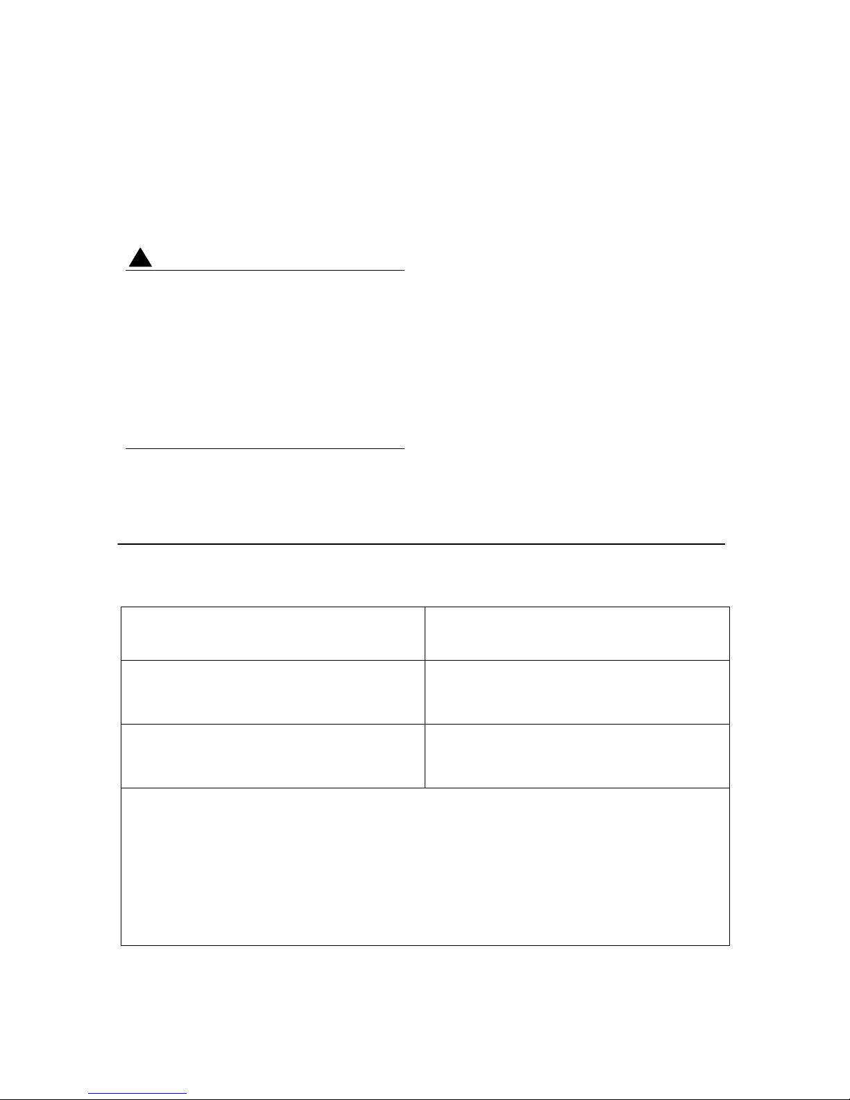
Check List of Mechanical Components for Proper Installation
NON-PRIORITY SYSTEM
PRIORITY SYSTEM
A) If separate circulator for each zone
• 1 circulator per zone
• 1 flow check per zone
A) If separate circulator for each zone
• 1 circulator per zone
• 1 flow check
B) If only one circulator used by the
heating system
• 1 zone valve per zone
B) If only one circulator used by the
heating system
• 1 – 3 way zone valve
C) Common Components:
• 4 x unions
• 4 x ball valves minimum
• 1 x vacuum breaker (if required)
• 1 x temperature & pressure relief valve
with probe of sufficient length.
• 1 x thermostatic mixing valve
• copper pipe & copper pipe fittings
•
steel pipe & steel pipe fittings
• 1 x potable water expansion tank if
necessary. See the “Domestic water
connections” section.
• 1 x pressure reducing valve (boiler
water)
• 1 x pneumatic expansion tank
• 2 x automatic air vents at least.
• Switching relays or zone controller
•
And any other necessary components.
CAUTION
!

TURBOMAX Use and Care Manual with Installation Instructions July 2014 Page 6
Installation
The manufacturer’s warranty does not cover
any damage or defect caused by installation
or attachment or use of any special
attachment other than those authorized by
the manufacturer into, onto, or in
conjunction with the water heater. The use
of such unauthorized devices may shorten
the life of the water heater and may endanger
life and property. The manufacturer
disclaims any responsibility for such loss or
injury resulting from the use of such
unauthorized devices
INSPECT SHIPMENT
Inspect the water heater for possible shipping
damage. The manufacturer’s responsibility
ceases upon delivery of goods to the carrier in
good condition. Consignee must file any claims
for damage, shortage in shipments, or nondelivery immediately against carrier.
DOMESTIC WATER CONNECTIONS
This water heater may be connected individually,
in multiples with others, or with an external hot
water storage tank. If two TURBOMAX® or more
are installed, the piping method to be used to
connect the TURBOMAX® in parallel should be
“reverse-return piping”, so domestic water flow
rate through each TURBOMAX® is equal.
The HOT WATER OUTLET and the COLD
WATER INLET connections are clearly marked.
Inlet water connections (COLD WATER INLET)
are to be made to the copper pipe (sweat
connection) at the bottom of the heater. Outlet
water connections (HOT WATER OUTLET) are
to be made to the copper pipe (sweat
connection) at the top of the heater.
The installation of copper unions or copper alloy
unions is recommended on the HOT and COLD
water lines, so that the water heater may be
easily disconnected for servicing if necessary.
Dielectric unions are required for protection of
the water heater if dissimilar pipe material like
galvanized pipe is used.
Install shutoff (ball) valves for servicing
convenience.
Use only clean copper or approved plastic pipe
for water connections. Local codes or
regulations shall govern the exact type of
material to be used.
To minimize heat loss during non-draw periods,
a heat trap formed from piping can be used.
Insulate all pipes containing hot water, especially
in unheated areas.
Cap or plug unused connections. If the water
heater is replacing a tankless coil in the boiler,
do not cap tube outlets in the tankless coil after
disconnecting from plumbing.
Thermometer(s) should be installed to indicate
the temperature of the water at or near the outlet
of the water heater and storage tank(s), if
provided.
EXPANSION TANK FOR POTABLE
WATER
Determine if there is a check valve, a back flow
preventer, a pressure-reducing valve, a water
meter or a water softener in the cold water
supply line.
A check valve creates a closed system and
prevents the water, as it is being heated, from
expanding back into the cold water supply line.
Pressure can build up within the water heater,
causing the relief valve to operate during a
heating cycle. This excessive operation can
cause premature failure of the relief valve and
possibly of the water heater itself.
Replacing the relief valve will not correct the
problem. One method of preventing pressure
build-up is to install an expansion tank for
potable water in the cold water supply line
between the heater and check valve. Contact
your installing contractor, water supplier, local
plumbing inspector or plumbing supply house for
assistance.
RECIRCULATION LINE (IF APPLICABLE)
If a recirculation line is installed, the return
connection should be made to a tee close to the
inlet connection on the water heater. A check
valve should always be installed in the
recirculation line to prevent cold water from
entering.
WARNING
!
TURBOMAX Use and Care Manual with Installation Instructions July 2014 Page 7
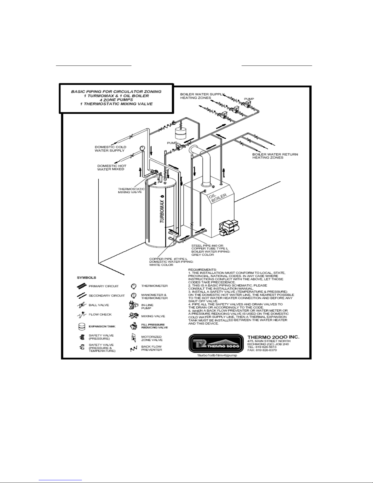
Basic Piping Schematic
Zone Valve Zoning
Requirements:
1. The installation must conform to local, state, provincial and national codes. In any case where instructions conflict
with the above, let those codes take precedence.
2. This is a basic piping schematic. It as to be adapted to your application.
3. Install a safety valve (temperature & pressure) on the domestic hot water line, as near as possible to the hot water
heater connection and before any shut off valve.
4. Pipe all the safety valves and drain valves to the drain or accordingly to the code.
5. When a back flow preventer or water meter or a pressure reducing valve is used on the domestic cold water supply
line, then a thermal expansion tank must be installed between the water heater and this device.

TURBOMAX Use and Care Manual with Installation Instructions July 2014 Page 8
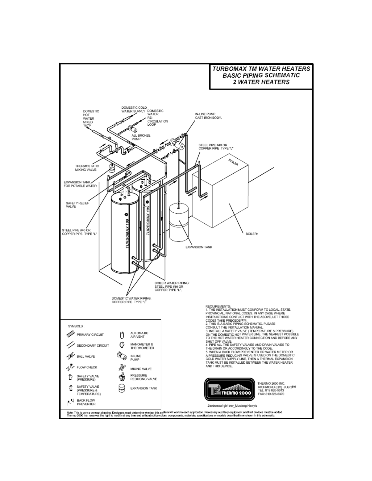
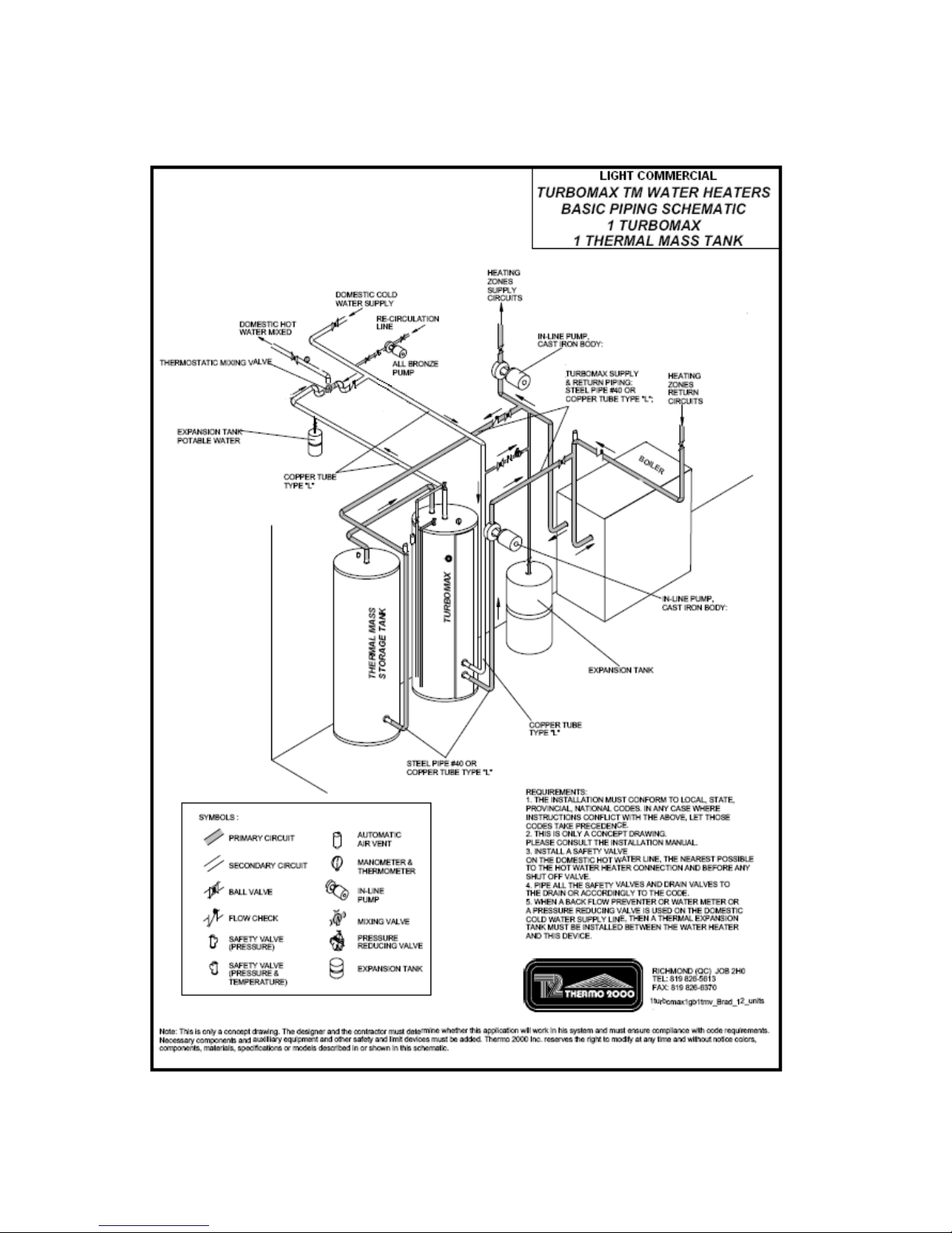
Basic Piping Schematic
Turbomax as a buffer tank
on a radiant floor system
Requirements:
1. The installation must conform to local, state, provincial and national codes. In any case where instructions conflict
with the above, let those codes take precedence.
2. This is a basic piping schematic. It as to be adapted to your application.
3. Install a safety valve (temperature & pressure) on the domestic hot water line, as near as possible to the hot water
heater connection and before any shut off valve.
4. Pipe all the safety valves and drain valves to the drain or accordingly to the code.
5. When a back flow preventer or water meter or a pressure reducing valve is used on the domestic cold water supply
line, then a thermal expansion tank must be installed between the water heater and this device.
TURBOMAX Use and Care Manual with Installation Instructions July 2014 Page 9
TURBOMAX Use and Care Manual with Installation Instructions July 2014 Page 10

TURBOMAX Use and Care Manual with Installation Instructions July 2014 Page 11
DOMESTIC HOT WATER TEMPERATURE
& PRESSURE RELIEF VALVE
An automatic temperature & pressure relief valve
with a temperature probe of sufficient length must
be installed at the time of the installation. No valve
of any type should be placed between the T&P
relief valve and the water heater. Use a tee to
install the relief valve onto the hot water outlet.
The pressure rating of the relief valve must not
exceed 150 psi.
The BTU per hour rating of the relief valve must
equal or exceed the BTU per hour input of the
boiler(s) or heat source(s) as marked on the
boiler(s) rating plate.
For a circulating tank installation, the separate
storage tank(s) must have similar protection.
Connect the outlet of the relief valve to a suitable
open drain, so discharge can exit only 6” above
the structural floor; and cannot contact any live
electrical parts. The discharge line must pitch
downward from the valve to allow complete
draining (by gravity) of the relief valve and
discharge line, and be no smaller than the outlet
of the valve. The end of the discharge line should
not be threaded or concealed and should be
protected from freezing. No valve of any type,
restriction or reducer coupling should be installed
in the discharge line. Local codes shall govern
the installation of relief valves.
THERMOSTATIC MIXING VALVE
When this water heater is supplying generalpurpose hot water requirements for use by
individuals, a thermostatically controlled mixing
valve is recommended to reduce the risk of scald
injury. Contact a licensed plumber or the local
plumbing authority for further information.
Keep temperature control of the mixing valve at
the lowest setting which is satisfactory.
When installing a mixing valve, locate it at the
bottom of anti-thermosiphon loop at least 24” high
to prevent excessive hot water from entering
mixed water supply.
VACUUM BREAKER (IF REQUIRED)
Install a vacuum breaker (or vacuum relief valve)
for water heater protection. Prevents siphoning of
the water from the system and collapse of the
water heater.
BOILER WATER CONNECTIONS
This water heater may be connected individually,
in multiples with others, or with an external
storage tank containing boiler water. If two
TURBOMAX® or more are installed, the piping
method to be used to connect the TURBOMAX® in
parallel should be “reverse-return piping”, so boiler
water flow rate through each TURBOMAX® is
equal.
The BOILER WATER SUPPLY and BOILER
WATER RETURN connections are clearly
marked. Boiler water supply connections are to
be made to the steel pipe (threaded connection) at
the top of the heater. Boiler water return
connections are to be made to the steel pipe
(threaded connection) at the bottom of the heater.
The installation of unions is recommended on the
BOILER WATER SUPPLY and BOILER WATER
RETURN lines, so that the water heater may be
easily disconnected for servicing if necessary.
Dielectric unions are required for protection of the
water heater and the pipes, if dissimilar pipe
material like galvanized pipe, copper and steel is
used.
Use only clean pipe for boiler water lines. Local
codes or regulations shall govern the exact type of
material to be used. Install shutoff (ball) valves for
servicing convenience. Thermometer(s) should be
installed to indicate the temperature of the boiler
water supply and return lines.
Circulator zoning recommendations
The preferred location of the circulator pumps for
each zone is on the boiler supply, with an
expansion tank between the boiler and the
circulators.
A flow check valve must be installed on each
zone, preferably at the outlet side of each
circulator pump, to prevent water flow to other
zones when they are not demanding flow
Zone valve zoning recommandations
The preferred location of the circulator pump is on
the boiler supply, with the expansion tank between
the boiler and the circulator.
Use zone valves with low pressure drop
specifications, particularly on the water heater
zone.
TURBOMAX Use and Care Manual with Installation Instructions July 2014 Page 12
PUMP & PIPE SIZING
Boiler water temperature drop (TD) through
the water heater
Simplified design methods based on a 20°F
temperature drop (TD) of boiler water going
through the water heater to heat up domestic
water are commonly used. Although such
methods are widely used and generate
satisfactory system performance when applied
properly, they do not determine the system
operating point. The pipe size is often
uneconomically large, and the actual system
flow rate is likely to be much higher than
intended. Such design methods seldom
consider temperature drops higher than 20°F,
which results in over-design.
Another method by which the boiler water
temperature drop (TD) could be calculated is to
assume a constant supply boiler water
temperature minus the domestic water final
temperature. For example a domestic water
heater might have a final temperature of 140 °F.
Assuming a constant supply boiler temperature
of 180 °F, the TD would be 40 °F
( = 180 °F – 140 °F). Second example: If the
domestic water heater has a final temperature of
180 °F and the boiler supply is at 200 °F, then
temperature drop is 20 °F (= 200 °F – 180 °F).
Precautions should be taken so that the boiler
return is above the boiler manufacturer’s lowest
recommended temperature. Most hot water
heating systems use standard, non-condensing
boilers (cast iron or steel), which must be
operated above 140°F in order to prevent the
corrosion that is associated with flue gas
condensation.
Alternatively, when the boiler surfaces are hot
due to previous loads such as domestic hot
water generation, the large temperature
difference between the boiler and its return
water can cause the boiler to become thermally
shocked.
An experienced designer could work with other
values than those proposed by looking into the
TURBOMAX performance tables and use the
guidelines stated above to design a state of the
art system.
The following chart proposes a temperature drop
(TD) that should be used to calculate the pump
flow rate.
Proposed boiler water temperature drop
through the water heater (TD)
Boiler water
supply
temperature
Domestic water
final
temperature
TD
200 °F 180 °F 20 °F
200 °F 160 °F 40 °F
180 °F 160 °F 20 °F
180 °F 140 °F 20 °F to 40 °F
180 °F 125 °F 20 °F to 40 °F
180 °F 110 °F 20 °F to 40 °F
160 °F 140 °F 20 °F
160 °F 125 °F 20 °F
160 °F 110 °F 20 °F
NOTE: The boiler water in TURBOMAX®
constitutes a store of heat energy ready to heat
fresh domestic water. The volume of boiler
water stored in TURBOMAX® tank provides
enough heat to keep your domestic hot water
hot while the boiler heats up. In fact, it acts as a
buffer, which prevents domestic hot water, or
boiler water temperature swings.
Pump flow rate calculation
The boiler’s output rating must be within the
heater’s the heat loads calculation or the sizing
guide recommendations. Use the equation
below to calculate the pump flow rate.
Pump flow rate = Boiler output ÷÷÷÷ TD ÷÷÷÷ 500
• Pump flow rate is express in U.S. gallons
per minute or GPM.
• The Boiler output ( in net BTU per hour) is
the maximum heat to be transferred through
the water heater to meet the hot water
demand.
• TD is the boiler water temperature drop
through the TURBOMAX®.
For example, a cast iron boiler has an output
rated at 90,000 BTU per hour. The system is
designed for a temperature drop (TD) of 20°F.
Pump flow rate = 90,000 ÷ 20 ÷ 500 = 9 GPM.
 Loading...