

THERMO 2000 MINI BTH 3, MINI BTH 6, MINI BTH 4.5, MINI BTH 7.5, MINI BTH 9 Installation & Operation Manual
...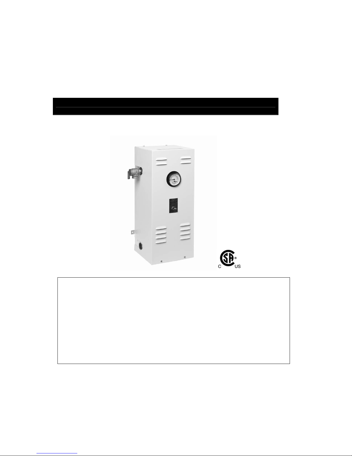
Electric Boilers
MINI BTH
M
odels from 3 kW to 12 kW :
208/240V single phase
INSTALLATION & OPERATING MANUAL
Your MINI BTH Electric Boiler has been carefully assembled and factory tested to provide
years of trouble-free service. The following information and safety measures are provided to
enable proper installation, operation, and maintenance of this product.
It is imperative that all persons who are expected to install, operate or adjust this boiler
should read these instructions carefully.
Any questions regarding the operation, maintenance, service or warranty of this electric
boiler should be directed to the supplier.
When all installation steps have been completed, insert this installation manual in its original
envelope, and keep in a safe place (close to the boiler) for future reference.
THERMO 2000 INCORPORATED revision: June 2014
Printed in Canada
BTH Electric Boilers USE & CARE MANUAL
(Revision Jun 2014)
, Page 2.
Ratings & Specifications at 240** Vac / 1ph (3 wires L1-N-L2) :
MINI BTH
Cable**!
90C/240V
Breaker!
**
Model Capacity*
KW/BTU/H
at 240V
Amps!*
at 240V
Electric
Element(s)
240V
Stage(
s) Cu Al
Amp. at
240V
MINI BTH 3 3 / 10,235 12.5 1 x 3 KW 1 12 10 20
MINI BTH 4.5 4.5 / 15,350 18.7 1 x 4.5 KW 1 12 10 25
MINI BTH 6 6 / 20,470 25 1 x 6 KW 1 8 6 40
MINI BTH 7.5 7.5 / 25,590 31 1X4.5+1X3KW 2 8 6 40
MINI BTH 9 9 / 30,710 37.5 2 x 4.5 KW 2 8 6 50
MINI BTH 12 12 / 40,940 50 2 x 6 KW 2 6 6 70
-Electric supply 120/240V or 120/208V 1 phase (L1-N-L2) with three conductors anc a ground
-Copper or Aluminum conductors can be used.
! Add the amperage (Max. 5amp) of the circulating pump if it is connected directly to the boiler
* On applications working at 208V/1ph, multiply the capacity by .75 and the amperage by .87
** A higher capacity cable could be required. In all cases the local Electrical Code has priority.
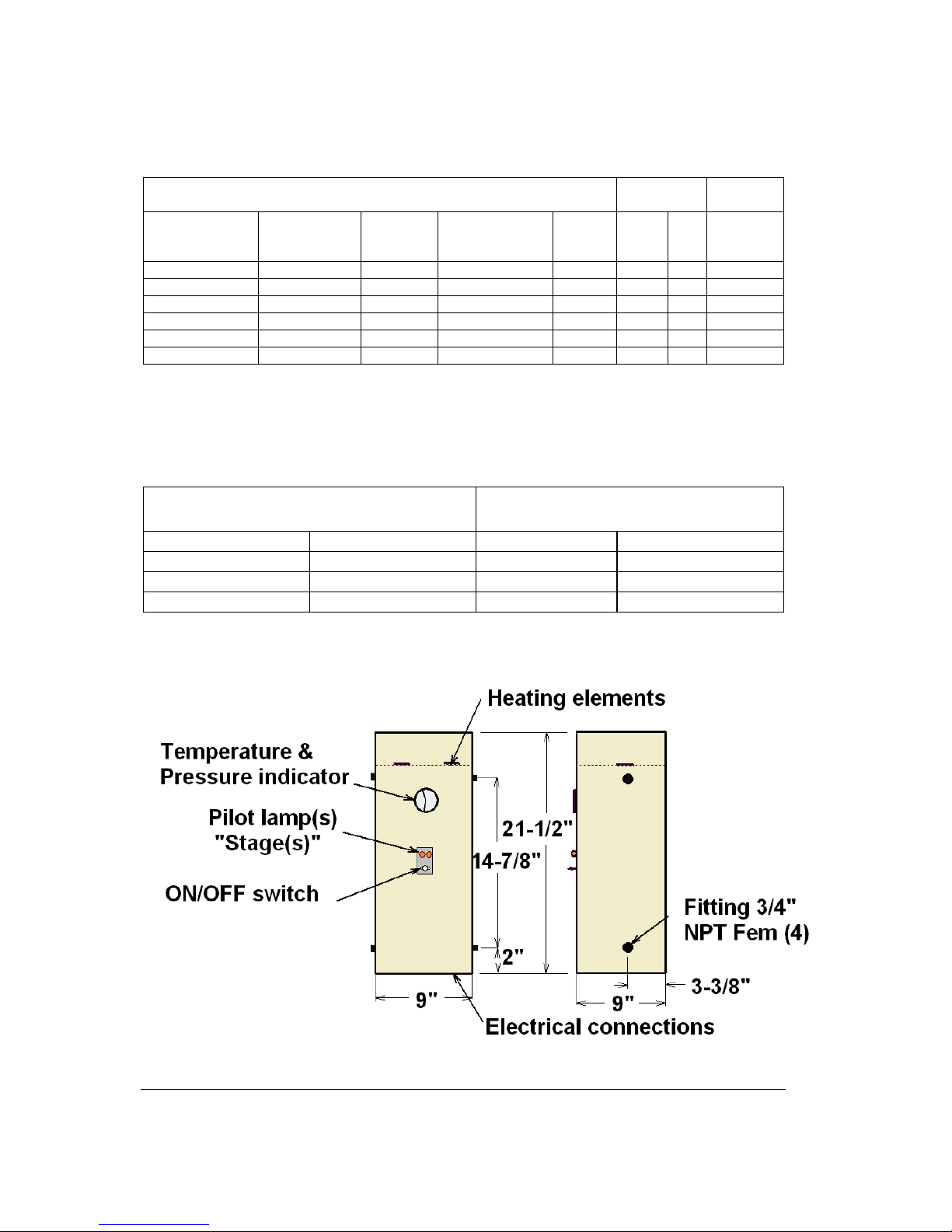
Dimensions
Connections Overall dimensions
Inlet/heating return 3/4 “ NPT Fem. Height 21-1/2 in.
Outlet/ heating supply 3/4 “ NPT Fem. Width 9in.
Pressure relief valve 3/4 “ NPT Fem. Depth 9 in.
Drain valve 3/4 “ NPT Fem. Shipment weight 40 lbs.
Operating temp. range: 50°F to 190°F. Maximum pressure : 30 psi
Boilers requiring to be built in conformity to ASME standards may be required in some
provinces or state. If such models are required, model with an “H” suffix shall be used.
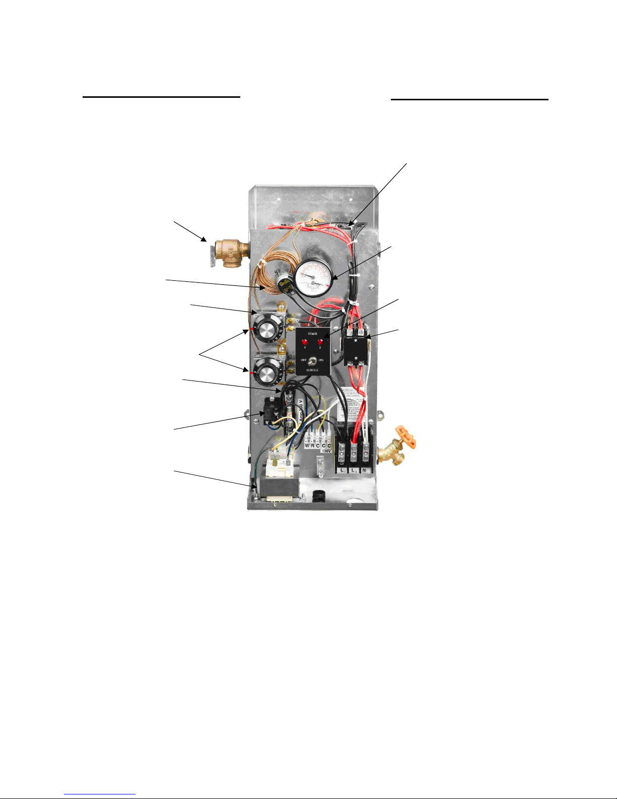
Figure 1.

BTH Electric Boilers USE & CARE MANUAL
(Revision Jun 2014)
, Page 3.
General Safety Precautions
Be sure to read and understand the entire Installation & operation manual before attempting to
install or to operate this water heater. Pay particular attention to the following General Safety
Precautions. Failure to follow these warnings could cause property damage, bodily injury or
death. Should you have any problems understanding the instructions in this manual, STOP,
and get help from a qualified installer or technician.
INTRODUCTION
These important safeguards and instruction
appearing in this manual are not meant to
cover all possible conditions and situations
that may occur. It should be understood that
common sense, caution and care are factors
which cannot be built into every product.
These factors must be supplied by the
person(s) caring for and operating the unit.
LOCAL INSTALLATION REGULATIONS
This electric boiler must be installed in
accordance with these instructions and in
conformity with local codes, or in the absence of
local codes, with the National Plumbing Code
and the National Electric Code, current edition.
In any case where instructions in this manual
differ from local or national codes, the local or
national codes take precedence.
Boilers requiring to be built in conformity to
ASME standards may be required in some
provinces or state. If such models are required,
model with an “H” suffix shall be used
SECURITY CONSIDERATIONS
Domestic and commercial installations have a
maximum design operating pressure limited to
30 psi by a safety relief valve.
Boiler maximum operating temperature is 190°F
by design. This boiler is designed to be used
only in a hot water heating system.
The heat transfer medium must be water or
other non-toxic fluid having a toxicity rating
or class of 1, as listed in clinical Toxicology
of Commercial products, 5th edition.
Concentration of propylene-glycol shall be
limited to 50%
CHECK LIST
Please check the identification tag on the unit to
make sure you have the right model.
List of components shipped with the unit :
• Pressure relief valve set at 30 PSI.
• Drain valve.
• Temperature & pressure indicator
(Factory installed).
SHIPMENT INSPECTION
Inspect the electric boiler for possible shipping
damage. The manufacturer’s responsibility
ceases upon delivery of goods to the carrier in
good condition. Consignee must file any claims
for damage, shortage in shipments, or nondelivery immediately against carrier.
!
WARNING
!
CAUTION
!

BTH Electric Boilers USE & CARE MANUAL
(Revision Jun 2014)
, Page 4.
INSTALLATION
The manufacturer’s warranty does not cover any damage or defect caused by installation, or
attachment, or use of any special attachment other than those authorized by the manufacturer
into, onto, or in conjunction with the water heater. The use of such unauthorized devices may
shorten the life of the boiler and may endanger life and property. The manufacturer disclaims any
responsibility for such loss or injury resulting from the use of such unauthorized devices
LOCATION
The electric boiler should be installed in a clean,
dry location. Long hot water lines should be
insulated to conserve water and energy. The
electric boiler and water lines should be
protected from exposure to freezing
temperature.
The electric boiler must be located or protected
so as not to be subject to physical damage, for
example, by moving vehicles, area flooding, etc.
The electric boiler should not be located in
an area where leakage of the tank or water
connections will result in damage to the
adjacent area or to lower floors of the
structure. When such areas cannot be
avoided, a suitable drain pan or nonflammable catch pan, adequately drained,
and must be installed under the boiler.
The pan must be connected to a drain.
NOTE: Auxiliary catch pan MUST conform to
local codes.
The boiler can be mounted directly on a wall
with adequate screws. Make sure it is properly
leveled.
All models in alcoves. The ambient temperature
must not exceed 90F
The electric boiler should not be located near an
air vent blowing a corrosive atmosphere or high
humidity. The limited warranty is void when the
failure of the electric boiler is due to a corrosive
atmosphere.
The choice of the mounting position of the boiler
shall be made in relation with the required
clearances shown below and the fact that the
electric element compartment of the boiler
needs clearance to allow their replacement.
°
CLEARANCE
For adequate inspection and servicing the
following minimum clearance is necessary:
Sides 4 inches
Electric elements side 14 inches
Front side of the boiler 24 inches
Back
0 inch
***
In Position #6 on models 3 to 6kW, the heating element must be relocated as shown.
Fig. 2 Mounting positions
CAUTION
!
WARNING
!
Original location
New location

BTH Electric Boilers USE & CARE MANUAL
(Revision Jun 2014)
, Page 5.
BOILER WATER CONNECTIONS
Make sure you connect the accessories and the piping to the proper connection fittings as indicated at figure
2 above and according the selected mounting position.
Figure 3 below shows typical connections of a MINI boiler to a radiant floor heating system. The location of
the distribution system components may be different from what is represented.
Figure 3 : Typical piping lay-out
Flow check valve
If the heating system includes a single pump,
without motorized zone valve and that the heating
distribution system is located above the boiler, a
flow check valve must be installed on the
supply distribution piping system to eliminate hot
water to flow by gravity in the heating distribution
piping when there is no heat demand. As an
alternative, a circulating pump incorporating a
spring check valve could be used.
On heating systems having more than one pump,
each pump will need to be equipped with a flow
check valve either incorporated into the pump or
separated.
On heating systems with motorized zone valves
this component is not required because the valve
stops all water flow when closed.
Pressure relief valve
This component supplied with the unit must be
installed directly to the boiler housing to the
appropriate connection according to the mounting
position.
Connect the outlet of the relief valve downward to
a safe location in case of discharge.
The piping diameter used for the discharge piping
shall not be smaller than that of the valve outlet. .
No valve of any type, restriction or reducer
coupling should be installed on the discharge line.
Local codes shall govern the installation of relief
valves.
Expansion tank
The expansion tank must be able to store the
required volume of boiler water during maximum
design operating temperature. The maximum
allowable operating pressure is 30PSI.Contact
your installing contractor, plumbing supply house,
or local plumbing inspector for assistance.
Water pressure makeup regulator
Make-up systems must be employed as required
by codes. An automatic fill valve must be used
with a backflow preventer as required, to maintain
minimum system pressure by supplying water to
make up for leakage.
The minimum pressure obtained when the system
is cold is generally of 12 psi.

BTH Electric Boilers USE & CARE MANUAL
(Revision Jun 2014)
, Page 6.
This accessory shall be equipped with one or
more check valves to avoid all possibilities of the
boiler water returning to the potable water supply
network.
Air bleeder
Installation of manual or automatic air vents are
required to eliminate all air from the boiler and the
heating distribution system.
Circulating pump
We recommend that the pump be installed at the
outlet of the boiler with isolating valves as shown
in figure 3.
The pump shall be selected such as to be able to
supply adequate flow in relation to the heating
distribution system on which it will be connected
and the heating capacity of the boiler installed.
The table below will give you details on required
water flow for distribution systems having to
operate with a differential temperature of 10F and
20F between their inlet and outlet
.
Model Diff.10F
usgpm
Diff. 20F
usgpm
Boiler press.
drop
MINI 3 2.0 1.0 Negligible
MINI 4.5 3.0 1.5 Negligible
MINI 6 4.0 2.0 Negligible
MINI 7.5 5.1 2.5 Negligible
MINI 9 6.0 3.0 Negligible
MINI 12 8.0 4.0 Negligible
Your heating wholesaler shall be in good position
to recommend the appropriate model for your
application.
The amperage drawn by the pump and other
120volts components shall not exceed 15 amps.
Drain valve
Installed at the lowest point of the unit, it allows
the unit to be drained for the eventual
replacement of a defective component.
Strainer
This component is used to collect potential
sediments coming from the distribution system
and more particularly from systems made of steel
piping and radiators. If such sediments
accumulate at the bottom of the boiler it could be
harmful to the heat transfer of the elements and
generate premature failures.
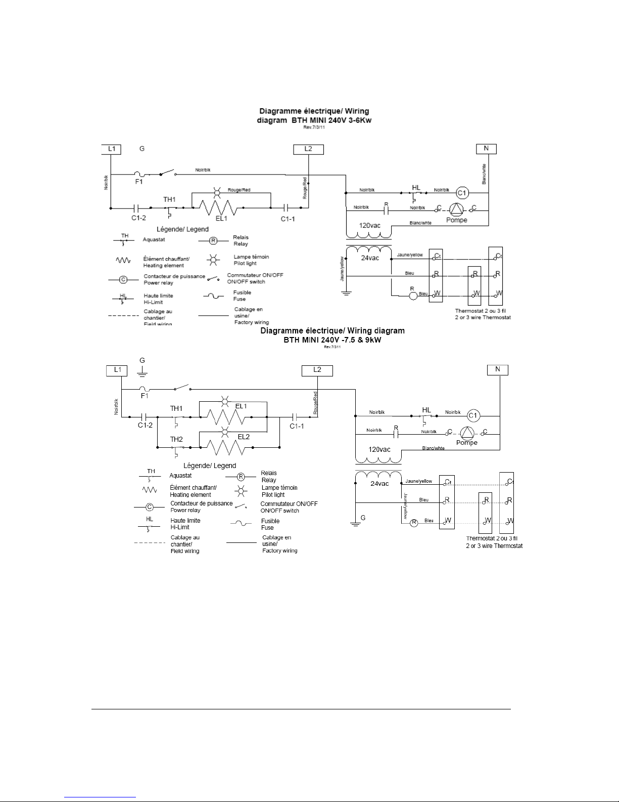
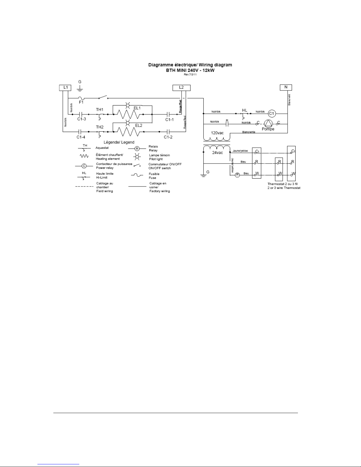
ELECTRICAL CONNECTIONS:
Main boiler supply
Wiring must conform to the National Electrical
Code and to state or local code requirements.
The electric boiler must be electrically grounded in
accordance with local codes, or, in the absence of
local codes, with the National Electrical Code.
Wiring must come from a 120/240 Vac/1ph or
208Vac/1ph “L1-L2-N” circuit protected by a
properly sized breaker.
Wire gage (3 wires+ground) must be properly
sized. Consult the boiler rating plate to select the
proper breaker and wire gage.
The main terminal block of the boiler is suitable for
#14 to #2 wires.
Supply cables can be made of Aluminum or
Copper and be rated for 90C (194F).
If aluminum cables are used, it shall be of an
adequate size (generally bigger) to meet the
National electrical code.
Electrical supply of External accessories
The total 120vac consumption of the boiler and
external accessories must not exceed 5A.
The maximum electrical consumption of 24vac
external accessories connected to R&C terminals
must not exceed 30Va. The available voltage at
the boiler transformer must not drop below 24Vac.

BTH Electric Boilers USE & CARE MANUAL
(Revision Jun 2014)
, Page 7.
Thermostat(s) and pump(s) connections:
Heating systems equipped with one
thermostat and one pump:
With a 18gauge cable, connect the room
thermostat directly to the following boiler
terminals.
Two wire thermostat: Terminals “R” and “W”
Three wire thermostat: Terminals “C”, “R” and “W”
Using 14 gauge wires, connect the circulating
pump directly to terminals “C” and “C” (120vac)
Multiple pumps zoning applications:
Components shall be connected in such a way
that when a thermostat is generating a heat
demand, only the corresponding pump be
operated.
To do so, you will need relays as illustrated below.
Boiler terminals CC-120 and C-R-W will not be
used.
Zoning applications with motorized
valves :
Connect the low voltage thermostat to the zone
valve. Components must be wired to ensure that
only the zone valve corresponding to the zone
calling for heat is actuated. When a zone valve
opens, it generally closes a switch that is
incorporated in it. Connect each switch to the “R”
& “W” terminals in the boiler.
Connect the circulator to terminals “C” and “C” in
the boiler.is powered on a demand from any zone.
The transformer used to power the zone valves
must be sized for the load represented by all zone
valves in the heating system.
BTH Electric Boilers USE & CARE MANUAL
(Revision Jun 2014)
, Page 8.
BTH Electric Boilers USE & CARE MANUAL
(Revision Jun 2014)
, Page 9.

BTH Electric Boilers USE & CARE MANUAL
(Revision Jun 2014)
, Page
10.
START UP OPERATION
Before operating this boiler, be sure to read and follow these instructions, as well as the warnings
printed in this manual. Failure to do so can result in unsafe operation of the boiler resulting in
property damage, bodily injury, or death. Should you have any problems reading, following or
difficulty in understanding the instructions in this manual, STOP, and get help from a qualified
person.
Do not turn on the boiler unless it is filled with water. Do not turn on the boiler if the cold water
supply shut-off valve is closed.
Preparatory step
Make sure that all the piping and
electrical connections have been made.
Fill the boiler and the heating system
with water.
Check for leaks.
Check the pressure reading at the
temperature and pressure indicator. It shall
be around 12psi.
Adjust the temperature control(s) to
OFF.
Turn the service switch in front of the
unit to ON
Set the thermostat ON to generate a
heat demand. The pump shall start.
Check that the water is circulating in the
distribution system and that all the air is
expelled.
Temperature control adjustment
Each temperature control has the function to
control one heating element.
Adjust each control to the desired temperature
by turning the knob of the control. The reference
mark for the adjustment is a red dot located
under the knob.
One control (any of the two) shall be set
at the maximum temperature required by the
heating system
The table below gives a good indication of the
temperature value generally required for
different applications.
Applica
tion
Baseboard
s
Cast
Iron
radiators
Warm
floor in
concrete
Warm
floorr
between
joists
Temp.
F
180 F 155 oF 115 oF 140 oF
Set the value of the second control
(Model of 9 to 12kW only) at
approximately 5F below the setting of
the first control.
The indicating lamp(s) on front of the unit shall
come ON as you increase the temperature of
the control(s).
On initial start up it may take a considerable
amount of time before the water reaches the
desired temperature
Further adjustments may be necessary as you
use your boiler and space heating system.
Inspection
Measure the amperage drawn by the
unit. It shall be around the value indicated
on the boiler name plate.
Partially close the isolating valve at the
outlet of the boiler to reduce the water flow
and consequently increase the outlet
temperature . Heating elements shall stop at
a temperature slightly higher than the
selected value on the controls
Lower the adjustment of the room
thermostat(s) The pump shall stop but the
element(s) will stay on if the temperature of
the water is under the setting temp. of the
control(s).
Check the pressure reading at the
gauge on the unit. It shall not be higher than
28psi when the distribution system will get to
its maximum operating temperature.
N.B.: This boiler is designed to be maintained
hot and consequently always ready to receive a
demand for heat all over the heating season. It
will then be normal to occasionally see an
indicating lamp in operation for a few seconds
even if there is no call for heat. It will also be
normal to occasionally see the temperature
value at the boiler gauge higher than the normal
values. This temperature will get back to normal
at the next heat demand.
SAFETY PRECAUTIONS
!

BTH Electric Boilers USE & CARE MANUAL
(Revision Jun 2014)
, Page
11.
MAINTENANCE
INTRODUCTION
Properly maintained, your boiler will provide years of dependable, trouble free service. It is recommended that a regular
routine maintenance program be established and followed by the user. Components are subject to eventual failure that
requires
service. Failure to use the correct procedures or parts in these circumstances may make the unit unsafe or reduce the
life of the boiler.
The owner should have the following inspection and maintenance procedures performed:
At all time
An immediate inspection shall be made if:
An odor of melted plastic or overheating
material is detected
A leak coming from the unit or the heating
system is observed
If a leak is detected at the outlet of the safety relief
valve, it could be related to a problem with components
installed on your heating distribution system. A quick
correction is then required.
Do not plug the outlet of this valve if a dripping
condition occurs.
Twice a year:
Check for the proper operation of the automatic
air purger(s) and eliminate air from the
radiators.
Annually:
It is recommended that a visual inspection be
made on the electrical compartments of the
boiler to check the stanchness of the gasket on
the element flange an also check for any
overheating signs of the components and wires.
Required corrections shall be made as soon as
possible.
Parts used for replacement shall be the same
as the original equipment.
Make sure that the power on the unit has been turn
off before opening the electrical compartments of
the boiler.
Close required isolating valves and clean the
strainer located on the heating return piping.
Open the boiler drain valve to eliminate
deposits that could have settle at the bottom of
the boiler. Stop when water gets clear. If there
is no flow or a very small flow, it could be due to
a large accumulation of deposits at the bottom
of the unit. If so, close the isolating valves at the
inlet and outlet of the boiler, remove heating
element(s) and clean the inside of the tank with
a strong jet of water
WARNING
!
BTH Electric Boilers USE & CARE MANUAL
(Revision Julne 2014), )
, Page
12.
REPLACEMENT PARTS
**When replacing an heating element, insure that its orientation is identical as the original
Heating Elements **
3kW : ZEL300-240V3KW
4.5kW : ZEL300-240V45KW
Temperature & Pressure
indicator
ZMC300-75P160C
Indicating lamp
ZEL150-240VRED
Contacteur
ZEL100-2PC50120
Contactor
Model 3;4.5;7.5;9kW :
ZEL100-2PC50120
Model 12kW :
ZEL100-4P50A120
Transformer
ZEL400-120V50VA
Pump Relay
ZEL100-24ACSPST
Fuse
ZEL250-TDCC15A
Temperature control
ZEL200-G111781
High Limit control
ZEL200-L6C732
Pressure Relief valve
ZMC200-SV30PSI1
Reference adjust. mark

BTH Electric Boilers USE & CARE MANUAL
(Revision Julne 2014), )
, Page
13.
MINI BTH
LIMITED WARRANTY
Warranty Coverage for Residential Installation.
Thermo 2000 Inc. hereby warrants to the original residential purchaser that the MINI
BTH tank installed in a residential setting shall be free of leaks during normal use
and service for a period of fifteen (15) years from the date of purchase as long as
the original residential purchaser owns the home in which the unit was originally
installed. Residential setting shall mean usage in a single-family dwelling in which
the consumer resides on a permanent basis. Also, residential setting shall mean use
in multiple family dwellings in which one (1) MINI BTH tank is to be use in only one
(1) dwelling. In the event that a leak should develop and occur within this limited
warranty period due to defective material or workmanship, such leak having been
verified by an authorized company representative, Thermo 2000 inc. will repair or
replace at our sole option the failed unit with the nearest comparable model at the
time of replacement.
The original residential purchaser is responsible for all costs associated with the
removal and reinstallation, shipping and handling to and from manufacturing plant.
The replacement unit will be warranted for the remaining portion of the original
Warranty.
Warranty Coverage for Commercial Installation.
Thermo 2000 Inc. warrants to the original purchaser that the MINI BTH tank installed
in a commercial setting for fifteen (15) years.
Commercial setting shall mean use in other than residential setting stated above in
the residential setting definition. In the event that a leak should develop and occur
within this limited warranty period due to defective material or workmanship, such
leak having been verified by an authorized company representative, Thermo 2000
inc. will repair or replace at our sole option the failed unit with the nearest
comparable model at the time of replacement.
The original purchaser is responsible for all costs associated with the removal and
reinstallation, shipping and handling to and from Manufacturer. The replacement
unit will be warranted for the remaining portion of the original Warranty.
Limited two years warranty on all MINI BTH components
& parts
All other MINI BTH components & parts are warranted for a period of two (2) years
against defects due to defective material or workmanship. The original purchaser
is responsible for all costs associated with the removal and reinstallation, shipping
and handling to and from Manufacturer. The components, repaired or replaced are
warranted for the residual period of the initial warranty on the unit.
Exclusions.
This warranty is void and shall not apply if:
1. Defects or malfunctions resulting from installation, repair, maintenance and/or
usage that are not done in conformity with the manufacturer’s installation
manual; or
2. Defects or malfunctions resulting from installation, maintenance, or repair that are
not done in accordance with regulations in force; or
3. Defects or malfunctions resulting from improper installation, maintenance or repair
done carelessly or resulting from consumer damage (improper maintenance,
misuse, abuse, accident or alteration); or
4. Installation in which a relief valve (pressure) is not installed or if it is not functioning
properly, or when it is not connected to a drain to avoid damage to the property; or
5. Installation in which liquid circulating in the tank does not remain in closed circuit or
installation in which piping is leaking; or
6. A polybutylene pipe or radiant panel installation without an oxygen absorption
barrier is used; or
7. Installation where the acidity of water is not within the normal Environmental
Protection Agency (EPA) (between pH 6.5 – 8.5) guidelines or the domestic water
contains abnormal levels of particulate matter or water exceeding 10.5 gpg; or
8. Your home contains any type of water softener system and the unit is not installed
and maintained in accordance with the manufacturer specifications; or
9. The MINI BTH unit is being subject to non authorized modifications; or
10. Defects or malfunction resulting of storing or handling done elsewhere than Thermo
2000’s manufacturing plant; or
11. Units on which the serial number is removed or obliterated.
Limitations.
Thermo 2000 shall not be responsible for any damage, loss, and inconvenience of any
nature whatsoever, directly or indirectly, relating to the breakdown or malfunction of the
unit. This warranty limits its beneficiary’s rights. Nevertheless, the beneficiary may have
other rights, which vary from state to state.
This warranty replaces any other expressed or implicit warranty and constitutes the sole
obligation of Thermo 2000 towards the consumer. The warranty does not cover cost of
removal, reinstallation or shipping to repair or replace the unit, nor administration fees
incurred by the original consumer purchaser.
Thermo 2000 reserves its rights to make changes in the details of design, construction, or
material, as shall in its judgment constitute an improvement of former practices.
This warranty is valid only for installations made within the territorial limits of Canada and
the United States.
Warranty service procedure
Only authorized MINI BTH dealers are permitted to perform warranty obligations. The
owner or its contractor must provide Thermo 2000’s head office or authorized depot with
defect unit together with the following information: MINI BTH model and serial number,
copy of the original sales receipt and owner’s identification certificate.
THERMO 2OOO INC.
500, 9e Avenue, Richmond (Qc) Canada J0B 2H0
Phone: (819) 826-5613 Fax: (819) 826-6370
www.thermo2000.com
 Loading...