

THERMO 2000 INSTOMAX 4.5, INSTOMAX 6, INSTOMAX 7.5, INSTOMAX 9, INSTOMAX 12 Installation Use And Care Manual
INSTOMAXTM
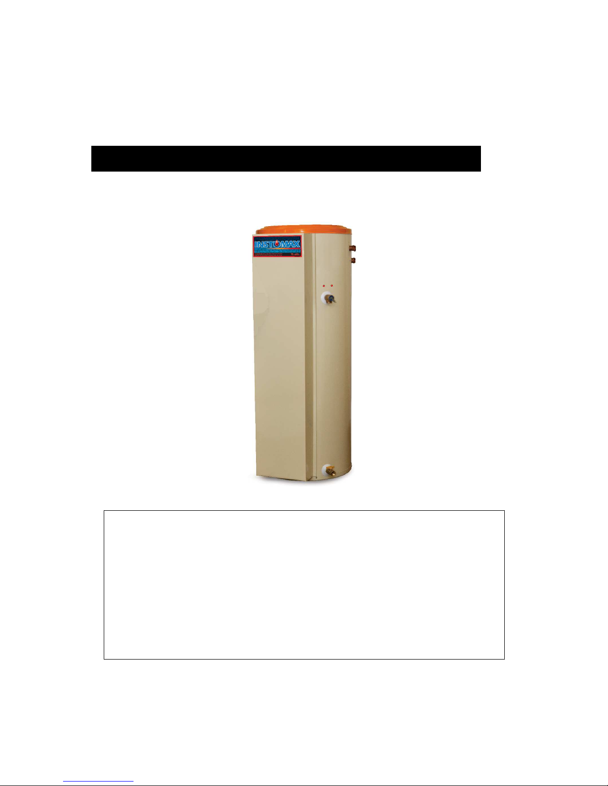
instantaneous water heater
Capacity from 4.5kW to 12kW :
208/240 Volts ( single phase )
INSTALLATION, USE AND CARE MANUAL
Your INSTOMAXMC water heater has been carefully assembled and factory tested to
provide years of trouble-free service. This manual contains instructions for the safe and
proper installation, operation and maintenance of the boiler, in order to insure your full
satisfaction.
Installer and user MUST read carefully and understand these instructions.
Any questions regarding the operation, maintenance, service or warranty of this appliance
should be directed to the dealer or distributor you purchased it from.
When all installation steps have been completed, replace this installation manual in its
original envelope, and keep in a safe place near the appliance, for further reference.
THERMO 2000 INC. revision: Sept. 2013
Printed in Canada

INSTOMAXTM Integrated instantaneous water heater installation, use and care manual
(Revision Sept 2013)
, Page 2.
Section 1: Technical specifications
Table 1: Boiler / heater specification 240*V/1PH (2 leads2) :
Suggested
conductor size
Model Input Heating
Current
draw
at 240V**
Suggested
fuse
kW/Mbtu Elements à 240v cu
al size**
INSTOMAX 4.5 4,5 / 15,3 1 x 4,5kW 19 12
10 25
INSTOMAX 6 6 / 20.5 1 x 6kW 25 8
6 40
INSTOMAX 7.5 7,5 / 25,6 1x4.5+1x3kW
31 8
6 40
INSTOMAX 9 9 / 30,7 2x4,5kW 38 8
6 50
INSTOMAX 12 12 / 41 2x6kW 50 6
6 70
*Can also be connected to a 208V/1ph source. This would provide 75% of the nominal capacity at 240V
**Suggested. Local code, regulations and authority having jurisdiction may require different wiring and
fuses.
Maximum operating pressure on the tank: 207kPa / 30psi
Tank temperature range : 10oC to 90oC (50oF to 190oF)
Table 2 : Dimensions:
Height : 1537mm (60-1/2’’)
With : 559mm (22’’)
Depth : 648mm (25-1/2’’)
Water connections :
o Supply fresh water inlet : 3/4"NPT Fem.
o Domestic hot water outlet : 3/4"NPT Fem.
o Expansion tank outlet : 1/2"NPT M.

INSTOMAXTM Integrated instantaneous water heater installation, use and care manual
(Revision Sept 2013)
, Page 3.
General Safety Precautions
Make sure to read and understand the entire Installation, Use and care Manual before
attempting to install or operate this INSTOMAXMC water heater. Pay particular attention to the
following “General Safety Precaution”. Failure to follow these WARNINGs may cause death,
bodily injuries or property damages. Should you have any problems understanding theses
instructions STOP and get help from a qualified technician or installer.
Section 2: INTRODUCTION
The important safeguards and instructions
appearing in this manual are not meant to
cover all possible conditions and situations
that may occur. It should be understood that
common sense, caution and care are factors
which cannot be built into every product.
These factors must be supplied by the
person(s) caring for and operating the unit.
2.1 GÉNERAL INFORMATION
The INSTOMAX™ is an instantaneous water
heater. It is composed of a thermal mass
reservoir filled either by water or other liquid and
a copper heat exchanger immersed in the
thermal fluid. Domestic fresh water passing
through the heat exchanger is heated by the
thermal fluid. Therefore the INSTOMAX™ has
two separate hydraulic circuits: The reservoir
(thermal mass) side and the domestic hot water
side located inside the heat exchanger.
2.2 LOCAL INSTALLATION
REGULATIONS
This water heater must be installed in
accordance with these instructions and must
conform to local codes, with the current edition
of the National Plumbing Code and the National
Electric Code. In any case where instructions in
this manual differ from local or national codes,
the local or national codes take precedence.
2.3 CORROSIVE ATMOSPHERE
The water heater should not be located near an
air supply containing halogenated hydrocarbons
or high humidity. Such localisation would void
any water heater warranty.
2.4 SHIPMENT INSPECTION
Upon reception, inspect the water heater for
possible shipping damage. The manufacturer’s
responsibility ceases upon delivery of the goods
in good condition to the carrier. Consignee must
file any claims for damage, shortage in
shipments or non-delivery immediately against
the carrier.
2.5 CHECK LIST
CHECK the boiler identification plate to insure
that you have received the right model.
Make sure that the following items are
included with the water heater:
• Tank 207 kPa (30 psi) pressure relief valve.
• Domestic hot water 860 kPa (125 psi)
pressure relief valve.
• Tank and domestic hot water heat
exchanger drain valve.
• Thermo manometer (heat and pressure
indicator).
• Automatic air vent.
• 83 kPa (12 psi) tank pressure regulator.
• Check valve with vacuum breaker.
• Thermostatic domestic water temperature
regulator.
• Electric heating elements and components.
• Aquastats temperature controller.
• Heating circuit expansion tank is supplied
with the water heater, but not installed.
The INSTOMAXTM water heater should not be
located in an area where leakage from the
tank or water connections will result in
damage to the adjacent area or lower floors
of the structure. When such areas cannot be
avoided, a suitable drain pan or nonflammable catch pan, adequately drained,
must be installer under the boiler. The pan
must be connected to a drain.
!
WARNING
!
WARNING
!

INSTOMAXTM Integrated instantaneous water heater installation, use and care manual
(Revision Sept 2013)
, Page 4.
Section 3: INSTALLATION
The manufacturer’s warranty does not cover
any damage or defect caused by installation
or attachment or use of any special
attachment other than those authorized by
the manufacturer into, onto, or in
conjunction with the water heater. The use of
such unauthorized devices may shorten the
life of the water heater and may endanger life
and property. The manufacturer disclaims
any responsibility for such loss or injury
resulting from the use of such unauthorized
devices.
3.1 SAFETY MEASURES
All domestic and commercial installations will
include a pressure relief valve limiting the
operating pressure to 207 kPa (30 psi) for the
INSTOMAX’s reservoir.
This INSTOMAX™ electric water heater is
designed for a maximum operating temperature
of 88°C (190°F). Typically, the tank’s thermal
mass liquid is tap water. If allowed by local
authorities and applicable code, a 30 to 50%
water and propylene-glycol blend can be used
for installation where supply fresh water
pressure is above 240 kPa (35 psig). Specific
equipment designed to avoid backflow to the
main water supply network might be required by
local installation codes.
3.2 EMPLACEMENT
The INSTOMAX™ water heater should be
installed in a clean, dry location. Long hot water
lines should be insulated to conserve water and
energy. The water heater and water piping
should be protected from exposure to freezing.
INSTOMAX™ water heaters must be installed
vertically. Use the adjustable feet to level the
unit.
The INSTOMAXTM water heater must be located
or protected so as not to be subject to physical
damage, for example, by moving vehicles, area
flooding, etc..
All models can be installed on combustible floors
and in alcoves. If the water heater is to be
installed in a restaurant or other location where
the floor is frequently cleaned, it must be
elevated to provide at least 150mm (6 inches) of
clearance from the floor to comply with NSF
International recommendations.
The room temperature must be maintained
between 10C (50F) and 33°C (90°F).
3.3 CLEARANCES
Minimum clearances required for inspection and
servicing are:
Tableau 4: Minimum clearances
Left side 0mm (0 in.)
Right side 0mm (0 in.)
Top 100mm (4 in.)
Front 400mm (16in)
Back 0mm (0 in.)
3.4 SYSTEM SETUP
Figures 1,2,3 illustrate components location and
a typical basic piping diagram. Additional
outboard mounted components may be required
in order to allow special application or local
codes and authorities having jurisdiction
requirements.
3.5 PIPING (see figures 1&2 for
identification and locations of components)
3.5.1 Tank pressure relief valve
The tank is protected with a pressure relief valve
set at 207 KPa (30 psig). NEVER replace this
pressure relief valve by a higher set pressure
one. Connect the supplied relief valve outlet
downward to insure that any expel water will be
directed toward a safe location. NEVER plug
the relief valve.
Piping diameter must not be smaller than the
pressure relief valve . The end of the piping
must be visible and not exposed to freezing.
3.5.2 Operating pressure control:
expansion tank:
The water heater is provided with a combination
pressure regulator / check valve allowing the
filling and pressurisation of the tank. The initial
pressure is generally of 83 kPa (12 psig).
In operation, water expansion will increase the
internal INSTOMAX™, pressure. Typical
operating pressure should be between 83 and
190 kPa (12 and 28psig) according to the tank
temperature.
WARNING
!
 Loading...