


GTH Electric Boilers
Models ranging from 6 kW to 36 kW :
240 Volts ( 1 phase ) & 600 Volts ( 3 phases ).
USE & CARE MANUAL
WITH INSTALLATION INSTRUCTIONS FOR THE CONTRACTOR
Your GTH Electric Boiler has been carefully assembled and factory tested to provide years
of trouble-free service. The following information and safety measures are provided to
enable proper installation, operation, and maintenance of this product.
It is imperative that all persons who are expected to install, operate or adjust this boiler
should read these instructions carefully.
Any questions regarding the operation, maintenance, service or warranty of this electric
boiler should be directed to the supplier.
When all installation steps have been completed, insert this installation manual in its original
envelope, and keep in a safe place (close to the boiler) for future reference.
THERMO 2000 INCORPORATED revision : November 2005
Printed in Canada
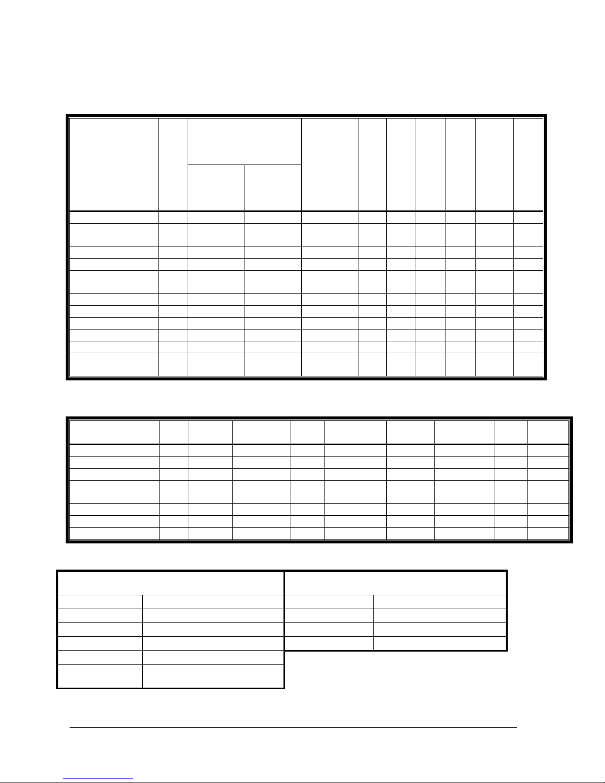
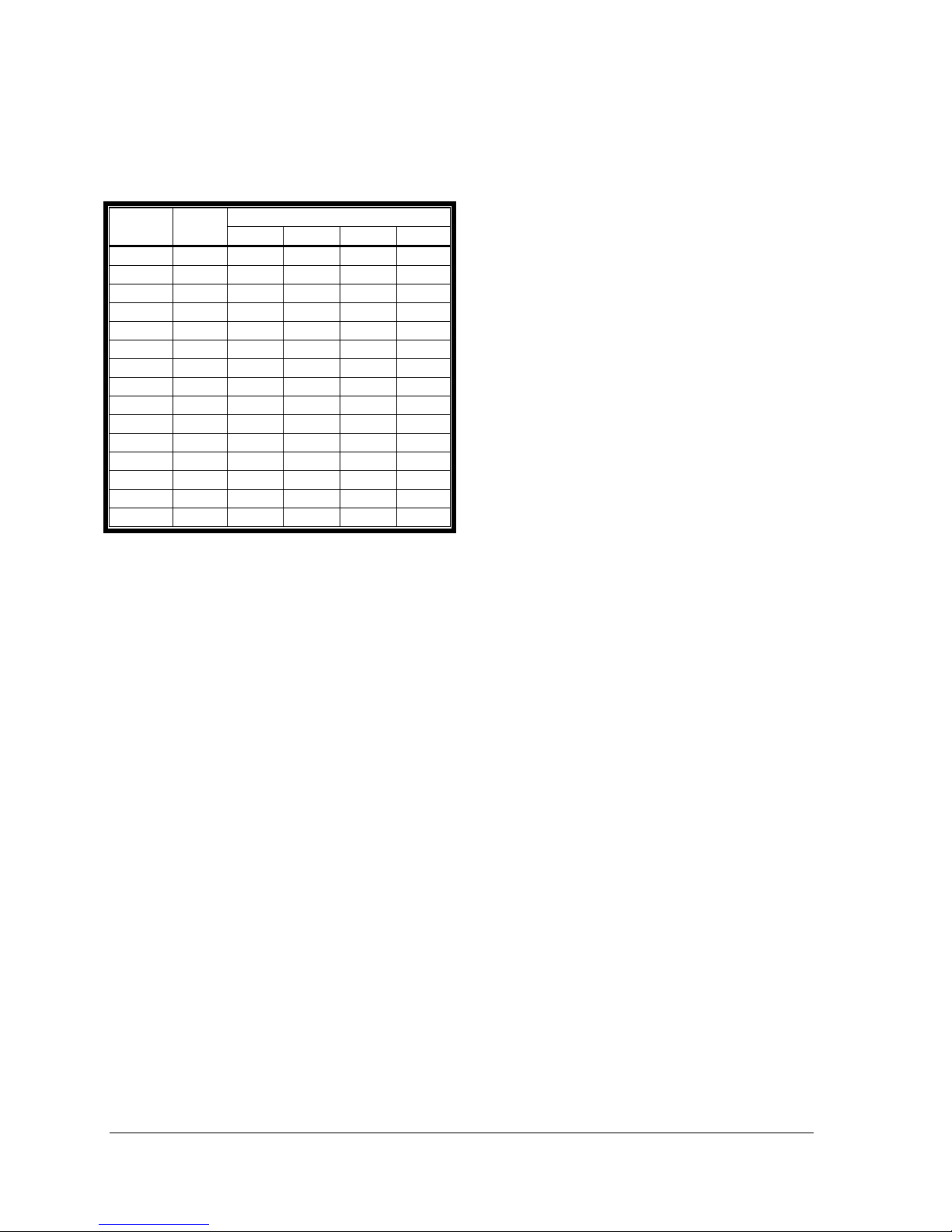
Section 1: Dimensions & Specifications
Table 1: Electric Ratings for 240 VAC (1 phase) Electric Boilers:
Current
Model
GTH 6 6 25.0 34.0 2 X 3KW 2 2 2 1 8 50
GTH 8 8 33.3 42.3
GTH 10 10 41.6 50.6 2 X 5KW 2 2 2 1 6 70
GTH 12 12 50.0 59.0 4 X 3KW 4 4 4 1 4 100
GTH 15 15 62.5 71.5
GTH 18 18 75.0 84.0 4 X 4.5KW 4 4 4 1 3 110
GTH 20 20 83.4 92.4 4 X 5KW 4 4 4 1 2 125
GTH 24 24 100.0 109.0 4 X 6KW 4 4 4 1 1 150
GTH 27 27 112.5 121.5 6 X 4.5KW 6 6 6 2 1/0 175
GTH 30 30 125.0 134.0 6 X 5KW 6 6 6 2 2/0 200
GTH 33 33 138.0 147.0
* Current for circulator (9 Amp max)
P
KW
Heating
Elements
Table 2: Electric Ratings for 600 VAC (3 phases) Electric Boilers:
P
Model
GTH 9 9 8.7 3 X 3KW 1 1 1 2 14 15
GTH 13 13.5 13.1 3 X 4.5KW 1 1 1 2 12 20
GTH 18 18 17.5 6 X 3KW 2 2 2 3 10 30
GTH 22 22.5 22.0
GTH 27 27 26.0 6 X 4.5KW 2 2 2 3 8 40
GTH 30 30 29.1 6 X 5KW 2 2 2 3 8 40
GTH 36 36 35.0 6 X 6KW 2 2 2 3 8 50
KW
Current
Amp
Amp
Total
with
Circulator
Elements
1X 3KW
1 X 5KW
2 X 3KW
2 X 4.5KW
3 X 5KW
3 X 6KW
Elements Stage Aquastats Lights Contactors
3 X 3KW
3 X 4.5KW
2 2 2 3 10 30
Wires
Stages
2 2 2 1 6 70
4 4 4 1 3 110
6 6 6 2 2/0 200
Lights
Aquastats
CU
Contactors
Fuse
Wires
CU
A
Fuse
A
Table 3: Connections sizes & Boiler overall dimensions
Connections sizes Boiler overall dimensions
Boiler return 1 “ NPT M Height 12 3/16 inches
Boiler feed 1 “ NPT M Width 16 7/16 inches
Waterworks 1/2 “ NPT F Depth 28 ½ inches
Safety valve 3/4 “ NPT F Shipping weight 99 lbs.
Drain valve 1/2 “ NPT F
Drain valve (GTH
33,36)
Operating temperature : from 50°F to 190°F.; Maximum operating pressure: 30 p.s.i.
3/4 “ NPT M
DTH Electric Boilers USE & CARE MANUAL (Revision November/05), Page 2.
2
8
1
/
2
"
C
A
F
B
E
D
I
M
16"
G
H
K
L
16 7/16"
12 3/16"
N
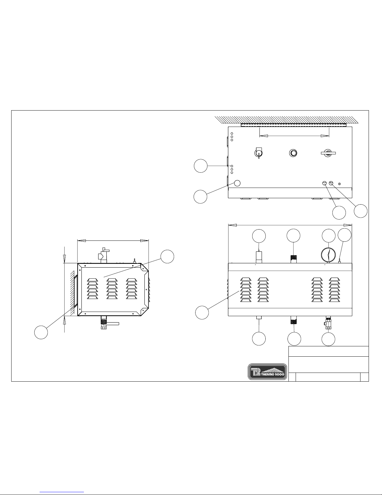
Legeng/Légende:
A) Boiler Water Supply Connection / Alimentation du chauffage (1" npt M)
B) Boiler Water Return/ Retour du chauffage (1" npt M)
C) Safety relief valve/ Soupape de sûreté (3/4" npt F.)
D) Temperature and pressur e G age/ Indicateur de Tempéra tur e et pr ession (1/2'' npt. F)
E) Drain Valve/ Valve de drainage (3/4'' npt M)
F) Fill Water Connection/ Entrée d'eau aqueduc (1/2" npt F)
G) Power supply wi r ing/Alimentation électrique
H) Pilot Ligh ts/ Lampe témoin
I) Electrical Compartments/ Co mpartiment électrique
J) Wall Brackets/ Supports mural
K) Circulator wiring/ Alimentation pompe
L) Thermostat wiring/ Connection thermostat
M) ON/OFF switch/ Interrupteur ON/OFF
N) Elements Co mpartments/ Compartiment d es éléments
J
THERMO 2000 inc.
SIZE
DWG. NO.
A
REV.
DESSIN D'ATELIER GTH/
GENERAL DIMENSIONS GTH
TH2-ATELIER
0
Figure 1
Page 3
General Safety Precautions
!
Be sure to read and understand the entire Use & Care Manual before attempting to install or to
operate this electric boiler. Pay particular attention to the following General Safety Precautions.
Failure to follow these warnings could cause property damage, bodily injury or death. Should
you have any problems understanding the instructions in this manual, STOP, and get help from
a qualified installer or technician.
Section 2: Introduction
WARNING
!
The important safeguards and instructions
appearing in this manual are not meant to
cover all possible conditions and situations
that may occur. It should be understood that
common sense, caution and care are factors
which cannot be built into every product.
They are the responsibility of the person(s)
caring for and operating the unit.
2.1 LOCAL INSTALLATION
REGULATIONS
This electric boiler must be installed in
accordance with these instructions and in
conformity with local codes, or in the absence of
local codes, with the National Plumbing Code
and the National Electric Code current edition.
In any case where instructions in this manual
differ from local or national codes, the local or
national codes take precedence.
2.2 CORROSIVE ATMOSPHERE
The electric boiler should not be located near an
air vent containing a corrosive atmosphere or
high humidity. The limited warranty is void when
the failure of the electric boiler is due to a
corrosive atmosphere.
2.3 INSPECT SHIPMENT
Inspect the electric boiler for possible shipping
damage. The manufacturer’s responsibility
ceases upon delivery of goods to the carrier in
good condition. Consignee must file any claims
for damage, shortage in shipments, or nondelivery immediately against carrier.
2.4 CHECK LIST
Please check the identification tag on the unit to
make sure you have the right model.
List of components shipped with the unit :
• Pressure relief valve set at 30 PSI.
• Drain valve.
• Tridicator (temperature & pressure
gage).
CAUTION
!
The electric boiler should not be located in
an area where leakage of the tank or water
connections will result in damage to the
adjacent area or to lower floors of the
structure. When such areas cannot be
avoided, a suitable drain pan or nonflammable catch pan, adequately drained,
must be installed under the boiler.
The pan must be connected to a drain.
NOTE: Auxiliary catch pan MUST conform to
local codes.
DTH Electric Boilers USE & CARE MANUAL (Revision November/05), Page 4.
Section 3: Installation
WARNING
!
The manufacturer’s warranty does not cover
any damage or defect caused by installation,
or attachment, or use of any special
attachment other than those authorized by
the manufacturer into, onto, or in
conjunction with the boiler. The use of such
unauthorized devices may shorten the life of
the boiler may endanger life and property.
The manufacturer disclaims any
responsibility for such loss or injury
resulting from the use of such unauthorized
devices
3.1 SECURITY CONSIDERATIONS
Domestic and commercial installations have a
maximum design operating pressure limited to
30 psi (207 kPa) by a safety relief valve.
Boiler maximum operating temperature is 190°F
by design. This boiler is designed to be used
only in a hot water heating system.
The heat transfer medium must be water or
other non-toxic fluid having a toxicity rating
or class of 1, as listed in clinical Toxicology
of Commercial products, 5
3.2 LOCATION
The electric boiler should be installed in a clean,
dry location. Long hot water lines should be
insulated to conserve water and energy. The
electric boiler and water lines should be
protected from exposure to freezing
temperatures.
The electric boiler must be installed horizontally,
directly on the wall. Use the wall mounting
brackets to make the unit level. The wall
mounting brackets are held by four 5/16’’ lag
screws. The openings are located at 16’’
intervals (i.e. standard stud spacing). When the
first bracket is installed you can hang the boiler
on the wall (see figure 1). The lag screws must
be suitably anchored to safely support the
weight of the boiler including water content,
piping and wiring.
CAUTION
!
th
edition
The electric boiler must be located or protected
so as not to be subject to physical damage, for
example, by moving vehicles, area flooding, etc.
All models can be installed on combustible floors
and in alcoves. Ambient temperature must not
exceed 80°F or 27°C.
3.3 CLEARANCE
Minimum clearances for adequate inspection
and servicing are listed in the following table:
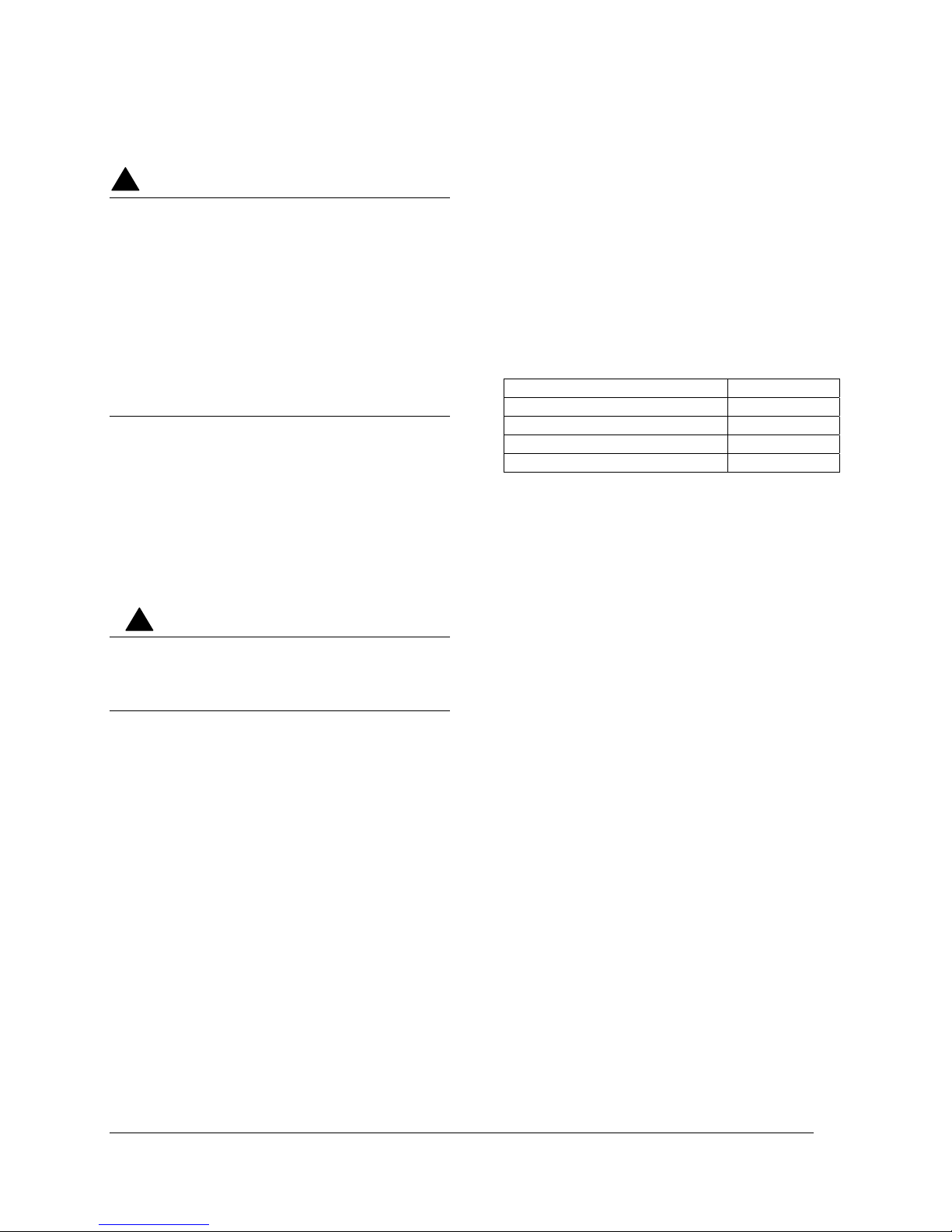
Table 4: Boiler clearance
Left side 16 inches
Right side 6 inches
Top & Bottom of the boiler 6 inches
Front side of the boiler 24 inches
Back side of the boiler 0 inch
3.4 PIPING
The recommended piping arrangement is shown
in figures 2, 3, 4 and 5, including the pump,
expansion tank, drain valve, pressure relief
valve, air vent, flow check valve and pressuretemperature gauge. Details about each item
follow.
3.4.1 Boiler connections
This electric boiler may be connected
individually or in parallel with other boilers. If two
or more boilers are connected, the “reversereturn piping” method (whereby the boiler with
the first return inlet also has the last supply
outlet and so forth until the last return inlet
corresponds to the first supply outlet) should be
used to connect the boilers in parallel, to ensure
an equal water flow rate through each boiler.
The BOILER WATER SUPPLY, located on the
top side, and the BOILER WATER RETURN,
located on the bottom side of the boiler are steel
pipes (male NPT threaded connection) where
supply and return line connections are to be
made.
Installing a union is recommended on the boiler
water supply and return lines to facilitate boiler
disconnection for servicing.
Dielectric unions are required for protection of
the boiler and piping if dissimilar pipe material
such as galvanized steel and copper are
present.
DTH Electric Boilers USE & CARE MANUAL (Revision November/05), Page 5.

Use only clean pipe for boiler water lines. Local
codes or regulations shall govern the exact type
of material to be used.
Insulate all pipes containing hot water,
especially in unheated areas.
Install shutoff (ball) valves for servicing
convenience. Thermometer(s) should be
installed on the boiler water supply and return
lines.
Cap or plug unused connections on the boiler.
Do not cap the pressure relief valve on the
boiler since it will damage and shorten the life of
the boiler and may endanger life and property.
3.4.2 Flow check valve
If the heating system is pipe to use only a single
pump, then to minimize flow by gravity & heat
loss during non-draw periods, a flow check
must
be installed.
3.4.3 Pressure relief valve
An automatic pressure relief valve must be
installed during boiler setup. The pressure
rating of the relief valve must not exceed 30 psi.
The safety relief valve must meet the
requirements of the ASME Boiler and Pressure
Vessel Code and limit the maximum operating
boiler pressure. It is a safety device, not an
operating control.
The BTU per hour rating of the relief valve must
equal or exceed the BTU per hour input of the
boiler(s) or heat source(s) as marked on the
boiler(s) rating plate.
Connect the outlet of the relief valve to a
discharge line with its lower tip at most 6” above
a floor drain, well clear of any live electrical
parts. The discharge line must pitch downward
from the valve to allow complete draining by
gravity of the relief valve and discharge line, and
be of a diameter no smaller than that of the
valve outlet. The tip of the discharge line should
not be threaded or concealed and should be
protected from freezing. No valve of any type,
restriction or reducer coupling should be
installed on the discharge line. Local codes
shall govern the installation of relief valves.
3.4.4 Piping system pressurization:
expansion tank
Pressure control devices within the system
ensure that each component operates within
minimum and maximum allowable pressures
and maintain minimum pressure for all normal
operating temperatures. They also allow air
bleeding, prevent cavitation at the pump inlet
and prevent water from boiling within the
system; all this is accomplished with minimal
addition of new water.
The increase in boiler water volume resulting
from higher temperature is stored in the
expansion tank during periods of high operating
temperature and is returned to the system when
the temperature decreases.
The expansion tank must be able to store the
required volume of boiler water during maximum
design operating temperature without exceeding
the maximum allowable operating pressure, and
to maintain the required minimum pressure
when the system is cold. Contact your installing
contractor, plumbing supply house, or local
plumbing inspector for assistance.
The point where the expansion tank is
connected should be carefully selected to avoid
the possibility that normal operation of automatic
check or manual valves will isolate the tank from
a hot boiler or any part of the system. Precharged diaphragm expansion tanks are
preferable to air control (see section 3.4.6).
These tanks incorporate a balloon-like bladder
or diaphragm. It is inflated, prior to filling the
system, to a pressure equal to the setting of the
water pressure makeup regulator.
The expansion tank should be located on the
suction or intake side of the pump. The pump
can be located either just upstream or just
downstream from the boiler.
3.4.5 Water pressure makeup regulator
Make-up systems must be employed as
required by codes. An automatic fill valve
must be used with a backflow preventer as
required, to maintain minimum system pressure
by supplying water to make up for leakage.
3.4.6 Air bleeder
Oxygen should be excluded from the system to
prevent corrosion. As hinted at in section 3.4.4,
DTH Electric Boilers USE & CARE MANUAL (Revision November/05), Page 6.

this precludes the use of air in direct contact with
the boiler water as a pressurization means.
Installation of manual or automatic air vent
devices prevents air from accumulating in the
system. Air vents should be installed at all high
points to remove trapped air during initial setup
and to ensure that the system is tight. Regularly
purge the air out of the system while taking care
to avoid personal injuries or property damage
caused by hot boiler water spray.
3.4.7 Circulator zoning recommendations
The preferred location of the circulator pump for
each zone is on the boiler supply side, with the
expansion tank between the boiler and the
pump.
A flow check valve must be installed in each
zone, preferably on the outlet side of each
circulator pump, to prevent water flow to other
zones where no heat is required.
3.4.8 Zone valve zoning
recommandations
The preferred location of the circulator pump is
on the boiler supply side, with the expansion
tank between the boiler and the circulator. Use
zone valves with low pressure drop.
3.4.9 Pump & pipe sizing
3.4.9.1 Boiler water temperature drop (BWTD)
through the heating loop
A simplified design method based on a 20°F
temperature drop (BWTD) between boiler outlet
and inlet is commonly used. Although such a
method is widely used and generates
satisfactory system performance when applied
properly, it does not determine the system
operating point. The pipe size is often
uneconomically large, and the actual system
flow rate is likely to be much higher than
intended. Such design methods seldom
consider temperature drops higher than 20°F,
which results in overdesign.
Another method by which the boiler water
temperature drop (BWTD) could be calculated
is to assume a constant supply boiler water
temperature minus the return boiler water
temperature. For example a boiler might have
a return temperature of 140 °F. Assuming a
constant supply boiler temperature of 180 °F,
the BWTD would be 40 °F ( = 180 °F – 140 °F).
Second example: If the boiler water has a return
temperature of 120 °F and the boiler supply is at
140 °F, then the temperature drop is 20 °F
(=140 °F – 120 °F).
The following table suggests temperature drops
(BWTD) to be used in calculating the pump flow
rate.
Table 5: Temperature rise through the boiler
PROPOSED BOILER WATER
TEMPERATURE RISE THROUGH THE
BOILER (BWTD)
System
type
Baseboards
Cast Iron
Radiators
Radiant
In-Floor
Boiler
water
Supply
tempera-
ture
190°F to
140°F
160°F to
130°F
130°F to
90°F
Boiler
water
Return
tempera-
ture
170°F to
120°F
140°F to
110°F
110°F to
70°F
BWTD
20°F to
40°F
20°F to
40°F
20°F to
40°F
3.4.9.2 Pump flow rate calculation
The boiler output rating must correspond to the
calculated heating load or be within the sizing
guide recommendations. Use the equation
below to calculate the pump flow rate.
Pump flow rate = Boiler output ÷
BWTD ÷ 500
• Pump flow rate is express in U.S. gallons
per minute or GPM.
• The Boiler output ( in net BTU per hour) is
the maximum heat to be transferred through
the heating loop to meet the heating load.
• BWTD is the boiler water temperature drop
For example, a 24KW electric boiler has a rated
output of 81,888 BTU per hour. The system is
designed for a temperature drop (BWTD) of
20°F.
Pump flow rate = 81,888 ÷ 20 ÷ 500 = 8,2 GPM.
DTH Electric Boilers USE & CARE MANUAL (Revision November/05), Page 7.
The following chart propose water temperature
rise vs flow rate in GPM.
Table 6: Temperature rise vs flow rate (GPM)
Model KW
o
10
F 20oF 30oF 40oF
BWTD
GTH 6 6 4,1 2,0 1,4 1,0
GTH 8 8 5,5 2,7 1,8 1,4
GTH 9 9 6,1 3,1 2,0 1,5
GTH 10 10 6,8 3,4 2,3 1,7
GTH 12 12 8,2 4,1 2,7 2,0
GTH 13 13,5 9,2 4,6 3,1 2,3
GTH 15 15 10,2 5,1 3,4 2,6
GTH 18 18 12,3 6,1 4,1 3,1
GTH 20 20 13,7 6,8 4,6 3,4
GTH 22 22,5 15,4 7,7 5,1 3,8
GTH 24 24 16,4 8,2 5,5 4,1
GTH 27 27 18,4 9,2 6,1 4,6
GTH 30 30 20,5 10,2 6,8 5,1
GTH 33 33 22,5 11,3 7,5 5,6
GTH 36 36 24,6 12,3 8,2 6,1
3.4.9.3 Pipe sizing criteria
Proper selection of pipe size is important to
efficient system operation. A large pipe size
results in lower friction losses and may allow the
selection of smaller, more economical pump.
The increased pipe size, however, costs more
initially and must be balanced against the cost
savings realized be smaller pump. Likewise,
small pipe costs less initially but must be
balanced against the increased operating cost of
pumping water through a system with high
friction losses. An economical balance should
be reached between pump size, operating costs,
and pipe diameter.
The ASHRAE fundamentals handbook states
the general range of pipe friction loss used for
the design of hydraulic systems and upper limits
of water velocity in piping.
A variety of upper limits of water velocity and/or
pressure drop in piping and piping systems are
used. One recommendation places a velocity
limit of 4 feet per second for 2 inch pipe and
smaller, and a pressure drop limit of 4 feet of
water per hundred feet for piping over 2 inches.
These limitations are imposed either to control
the levels of pipe and valve noise, erosion and
water hammer pressure or for economic
reasons.
Please note that in the smaller pipe sizes, this
velocity limit permits the use of friction loss rates
higher than 4 feet per 100 feet.
Fluid velocity should be above 1-1/2 to 2 feet per
second in order to carry entrained air along to a
high point in the system where it can be purged.
It is generally accepted that if proper air control
is provided to eliminate air and turbulence in the
system, the maximum flow rate can be
established by a piping friction loss rate of 4 feet
of water per 100 feet. This allows velocities
greater than 4 feet per second in pipe sizes 2
inches and larger.
As piping ages, friction losses increase. It is
recommended that for most commercial design
purposes a safety factor of 10 to 15 % be added
to the values in the tables.
What is a “foot of water”? A column of water at
60°F, 5 feet tall, creates a constant pressure of 5
feet of water at the bottom of the column. If the
water column is 2.31 feet tall, the mass of water
creates a constant pressure (head) of one (1)
psi (pound per square inch). Pressure losses are
expressed either in “feet of water” or in psi.
Pump manufacturers usually prefer feet of water
units.
3.4.9.4 Pump or circulator selection
Performance characteristics of centrifugal
pumps are described by pump curves, which
plot flow versus head or pressure together with
other information such as efficiency and power.
Consult the manufacturer’s pump curves to
select the proper model or ask your pump dealer
or your HVAC wholesaler for a recommendation.
3.5 ELECTRIC POWER SUPPLY
Wiring must conform to the National Electrical
Code and to state or local code requirements.
The electric boiler must be electrically grounded
in accordance with local codes, or, in the
absence of local codes, with the National
Electrical Code.
3.5.1 240Vac models
Wiring must be from a 120/240 Volt (single
phase, 60 Hz) circuit protected by a properly
sized breaker. Wire gage (3 wires, ground)
must be properly sized. Consult the boiler rating
plate to select the proper breaker and wire gage
DTH Electric Boilers USE & CARE MANUAL (Revision November/05), Page 8.

3.5.2 600Vac models
Line wiring must be from a 600 Volt ( 3 phase,
60 Hz) circuit protected by a properly sized
breaker. Wire gage (3 wires, ground) must be
properly sized. Consult the boiler rating plate to
select the proper breaker and wire gage.
3.6 PUMP POWER SUPPLY
3.6.1 240Vac models
Connect only a 120 Vac, 9 amp. (maximum)
pump to terminals C and C on the electric
pannel. Do not use a 600 Vac pump or one
drawing more than 9 amps. The logic circuit is
designed to activate the circulator based only on
demand by the thermostat after a time delay.
3.6.2 600Vac models
Use a relay (Honeywell #RA-889, RA-89A) or
the secondary contact of a zone valve (if the
heating system is zoned using 4-wire zone
valves). When a thermostat calls for heat: the
relay will power either the boiler pump or the
zone valve (the zone valve will power the boiler
pump upon opening fully). See figure 6 for more
details.
If the heating system is designed to use only a
single pump, then to minimize flow by gravity
and heat loss during non-draw periods, a flow
check must
be installed.
3.7 CONNECTING THE THERMOSTAT
3.7.1 For 240Vac model
3.7.1.1 Single heating zone
Connect a low voltage thermostat to terminals T
and T on the electric panel (DO NOT apply any
power to these terminals!).
3.7.1.2 Multiple heating zones
Connect the zone valve end switch to terminals
T and T on the electric pannel (DO NOT apply
any power to these terminals!). See figure 6.
3.7.2 For 600Vac model
3.7.2.1 Single heating zone
Connect the low voltage thermostat to a relay
(Honeywell #RA-889, RA-89A). See figure 6.
3.7.2.2 Multiple heating zones
Zone valve zoning
Connect the low voltage thermostat to the zone
valve. Components must be wired to ensure that
only the zone valve corresponding to the zone
calling for heat is actuated and that the circulator
is powered on a demand from any zone.The
transformer used to power the zone valves must
be sized for the load represented by all zone
valves in the heating system. See figure 6.
Circulator zoning
Connect the low voltage thermostat to the relay
(Honeywell #RA-889, RA-89A). Components
must be wired to ensure that only the circulator
corresponding to the zone calling for heat is
actuated. See figure 6.
DTH Electric Boilers USE & CARE MANUAL (Revision November/05), Page 9.

3.8 CBE-EM DUAL ENERGY
INSTALLATION
In order to obtain a special rate from your
electric utility for residential use, your GTH boiler
can be hooked-up to an existing oil heater.
Contact your electric utility to find out if your
property is eligible for such rates and how to
register for them. For installations instructions,
refer to figure 12, 13 and 14.
The CBE-EM dual-energy control (an available
option, three-way, motorized valve (1’’ NPT F
standard) included) is specially designed to
electric utility standards. The CBE-EM control
selects the least expensive energy source based
on outside temperature, user choice or a signal
from your utility.
The CBE-EM dual-energy control will start up
the oil burner upon receiving the appropriate
signal, even if the thermostat in the house is not
calling for heat. It will shut off when the
temperature in the boiler reaches its target on
the Limit Control. It is for this reason that the
piping requires an anti-gravity valve (flow check
valve) or motorized zone valves.
A three-way, motorized valve (1’’ NPT F
standard) will direct the water flow either to the
oil-fired heater or to your DTH electric boiler,
depending on the signal received. This way,
your oil heater will cool down and eliminate any
energy loss, either through the chimney or by
way of conduction in the boiler room.
DTH Electric Boilers USE & CARE MANUAL (Revision November/05), Page 10.

Section 4: Operation
SAFETY PRECAUTIONS !
Before operating this boiler, be sure to read
and follow these instructions, as well as the
warnings printed in this manual. Failure to
do so can result in unsafe operation of the
boiler resulting in property damage, bodily
injury, or death. Should you have any
problems reading, following or difficulty in
understanding the instructions in this
manual, STOP, and get help from a qualified
person.
Do not turn on the boiler unless it is filled
with water. Do not turn on the boiler if the
cold water supply shut-off valve is closed.
After the boiler has been plumbed and wired, it
is now ready to be set for automatic operation.
4.1 FILLING THE BOILER
Open the shutoff valve (and on a zone valve
system, manually open zone valve) on the
supply piping from the boiler.
Open cold water supply valve (fill or makeup
water valve) to boiler.
To let the air out of the boiler tank during the fill
process open the relief valve on top of the
boiler.
Leave all shutoff valves open. Return zone
valves to automatic operation.
Check system for leaks and repair.
Purge air from the remaining zones, if
necessary. Check boiler pressure gage reading.
15 to 20 psi is normal for most installations.
4.2 AQUASTAT ADJUSTMENT
After the system has been manually purged of
air, and all components (valves, vents,
controllers) have been set properly, the boiler
can be started. Never operate this boiler until
this has been done.
Safety and energy conservation are factors to be
considered when setting the boiler water
temperature using the aquastats. The most
energy-efficient operation will result when the
temperature setting of each aquastat is the
lowest that satisfies the heating needs.
refer to table 5 for more details.
Each aquastat controls one stage (in the 240V
model each electric element has it own
aquastat; in the 600V model there is one
aquastat per 3 elements). Set the temperature
on the aquastat using the knob graduated in
degrees Celsius and Fahrenheit.
Set the temperature on the first aquastat to the
highest supply temperature required by the
heating system.
Please
Set the temperature on the second aquastat
from 1°F to 20°F below the setpoint of the first
aquastat. Usually 5°F below the setpoint of the
first aquastat is adequate if the boiler water
temperature drop is 20°F.
Proceed in a similar manner for the 3rd, 4th and
any supplementary aquastats, lowering the set
point by 5°F each time.The elements will thus be
activated (and de-activated) in the number
required by the set points and the drop (or rise)
in boiler water temperature.
On initial start up (on the first day of the heating
season) with a cold tank, a considerable amount
of time may be required for the tank to reach
desired temperature. Check the temperature on
the boiler temperature gage.
Adjust the boiler aquastats as needed. Note
that setting the aquastat to a lower setting will
not have an immediate effect. The stored boiler
water heat will first have to be consumed.
Additional checks of the water temperature
should follow completion of a cycle. Further
adjustments may be necessary as you use your
boiler and space heating system.
Note: The maximum setting for the boiler water
supply to the heating system is 190°F.
DTH Electric Boilers USE & CARE MANUAL (Revision November/05), Page 11.

4.3 STARTUP PROCEDURE
1. Fill the boiler as described in section
4.1.
2. Set the boiler operating temperature as
described in section 4.2.
3. Turn down all room thermostats under
room temperature
4. Turn on the boiler power breakers and
switch.
5. The main contactor should close and all
elements should be in operation. Pilot
lights should be on.
6. Temperature inside the boiler should
increase. Elements and pilot lights
should turn off one by one as they reach
their set point.
7. When all elements are off, turn up all
room thermostats above room
temperature.
8. The circulator should start up after a
time delay.
9. The elements should turn on in
sequence as the boiler water
temperature drops below the aquastat
set points. This could take many
minutes.
10. The circulator stays on for as long as
there is a demand for heating. When the
circulator turns off,
11. Temperature inside the boiler should
increase. Elements and pilot lights
should turn off one by one at they reach
their aquastat set point.
In this way, the power drawn by the boiler
depends on the actual heating load of the
building. If you need only one stage to heat your
home, only one will be turned on; if you need
two stages, two will be turned on. Excessive
cycling and wear and tear of electric
components will be avoided, thus increasing
their life reducing heating cost.
DTH Electric Boilers USE & CARE MANUAL (Revision November/05), Page 12.

R
Section 5: Maintenance
Properly maintained, your boiler will provide years of
dependable, trouble free service. It is recommended
that a regular routine maintenance program be
established and followed by the user. Components
are subject to eventual failure that requires service.
Failure to use the correct procedures or parts in
these circumstances may make the unit unsafe or
reduce the life of the boiler.
The owner should have the following inspection and
maintenance procedures performed:
5.1 BOILER WATER PIPING:
Yearly visual inspection.
Check all piping for signs of leakage near joints,
unions and shut-off valves. Repair as needed.
5.2 PRESSURE RELIEF VALVE ON TOP OF
BOILER:
Monthly inspection.
Must be manually operated to ensure safe and
proper operation. By opening the pressure relief
valve, the air trapped inside the heater tank is
purged.
Make sure that the discharged water is directed to a
suitable drain or other collection device, and will not
spray onto anyone. Use the lever on the pressure
relief valve to open. A steady discharge of hot water
should occur. After releasing this lever the safety
relief valve should close and fully shut off this flow.
If the pressure relief valve does not function
properly, it must be replaced with the same model or
its equivalent. Do not plug the outlet of this valve if a
dripping condition occurs.
5.3 BOILER PURGE
Yearly.
It is recommended that the boiler be purged
annually, in order to eliminate sediment and sludge
which may have accumulated at the bottom of the
boiler and covered the heating elements.
Procedure
1. Let the boiler cool down
2. Close the maintenance valves connected to
the boiler inlet and outlet. N.B.: It is not
recommended to drain the water from the
whole heating system.
3. Hook-up a garden hose to the drain valve
and place it close to a floor drain.
4. Open the purge valve until the water comes
out clean and clear
5. Close the valve
It is recommended to perform a visual inspection of
the boiler electrical compartment annually, during
the heating season, to ensure it is watertight and
that there are no signs of component or wiring
overheating. Repair as soon as possible if
necessary. Defective components should always be
replaced with the Original Manufacturer’s parts.
The manufacturer’s warranties DO NOT cover
tank failure due to improper installation or
maintenance. If the pressure relief valve on the
heater discharges periodically, this may be due
to thermal expansion. Immediately call a
qualified service technician to inspect and to
remedy as needed.
NOTE: To prevent premature tank failure, the air
trapped inside the tank must be purged
periodically. Use the safety relief valve on top of
the tank to perform this task.
Before manually operating the relief valve, make
certain no one will be sprayed with the hot water
released by its opening. The water may be hot
enough to create a SCALD hazard. The water
released should be directed to a suitable drain to
prevent injury or damage.
WARNING
!
DANGE
!

1
2
3
4
5
6
7
8
9
10
11
12
13
L1 L2 N
T T
C C
Legeng/Légende:
1) Main water supply / Alimentation d'ea u
2) Maintenance valve/ Valve d'entretien
3) Check valve/ Clapet anti-retour
4) Pressure reducer/ Réducteur de pression
5) Expension tank/ Réservoir d'expansion
6) Circulating pump/ Pompe circulatrice
7) Purge valve/ Robinet élimination d'a ir
8) Drain valve/ Valve drainage
9) Safety valve/ Valve de sécurité
10) T & P Gage/ Tridicateur
11) Automatic air vent/ Purgeur d'air
12) Flow check valve/ C lapet antigravité
(required on systems without motorised zone valves)
(requise sur les systèmes n'ayant pas de valv es motorisées)
13) Thermostat/ Thermostat
Schéma d'installation général/
General installation
GTH 240V
Simple zone/
Single zone
THERMO 2000 inc.
GTH
Raccordement de pompe G TH 600V/
Pump wiring GTH 600V
T T
1
2
3
4
L2 L1
Pompe/Pump
jumper
Thermostat
Relais/Relay
RA89A
120Vac
Figure 2
Figure 14

1
2
3
4
5
6
7
8
9
10
11
12
13
14
15
L1 L2 N
T T
C C
Legeng/Légende:
1) Main water supply / Alimentation d'ea u
2) Maintenance valve/ Valve d'entretien
3) Check valve/ Clapet anti-retour
4) Pressure reducer/ Réducteur de pression
5) Expension tank/ Réservoir d'expansion
6) Circulating pump/ Pompe circulatrice
7) Purge valve/ Robinet élimination d'a ir
8) Drain valve/ Valve drainage
9) Safety valve/ Valve de sécurité
10) T & P Gage/ Tridicateur
11) Automatic air vent/ Purgeur d'air
12) Flow check valve/ C lapet antigravité
(required on systems without motorised zone valves)
(requise sur les systèmes n'ayant pas de valv es motorisées)
13) Motorized zone va lve/ Soupape électrique de zone
14) Hot water baseboard/ Plinthes chauff age
15) Thermostat/ Thermostat
Schéma d'installation général/
General installation
THERMO 2000 inc.
GTH 240V
Zonage de plinthes/
Valve zoning to baseboard
Figure 3
Page 15

1
2
3
4
5
6
7
8
9
10
11
12
15
L1 L2 N
T T
C C
Legeng/Légende:
1) Main water supply / Alimentation d'ea u
2) Maintenance valve/ Valve d'entretien
3) Check valve/ Clapet anti-retour
4) Pressure reducer/ Réducteur de pression
5) Expension tank/ Réservoir d'expansion
6) Circulating pump/ Pompe circulatrice
7) Purge valve/ Robinet élimination d'a ir
8) Drain valve/ Valve drainage
9) Safety valve/ Valve de sécurité
10) T & P Gage/ Tridicateur
11) Automatic air vent/ Purgeur d'air
12) Flow check valve/ C lapet antigravité
13) Return header/ Collecteur de retour
14) Radiant infloor piping/ Plancher chauffant
15) Thermostat/ Thermostat
16) Supply header/ Collecteur d'alimentation
14
13
16
T=105 F
T=90 F
Schéma d'installation général/
General installation
THERMO 2000 inc.
GTH 240V
Plancher chauffant direct/
Direct radiant heating loop
Figure 4
Page 16

1
2
3
4
5
6
7
8
9
10
11
12
15
L1 L2 N
T T
C C
Legeng/Légende:
1) Main water supply / Alimentation d'eau
2) Maintenance valve/ Valve d'entretien
3) Check valve/ Clapet anti-retour
4) Pressure reducer/ Réducteur de pression
5) Expension tank/ Réservoir d'expansion
6) Circulating pump/ Pompe circulatrice
7) Purge valve/ Robinet élimination d'air
8) Drain valve/ Valve drainage
9) Safety valve/ Valve d e sécur ité
10) T & P Gage/ Tridicateur
11) Automatic air vent/ Purgeur d'air
12) Injection valve/ Valve d'injection
13) Return header/ Collecteur de retour
14) Radiant infloor piping/ Plancher chauffant
15) Thermostat/ Thermostat
16) Supply header/ Collecteur d'alimentation
17) Circuit balancing valve/
Valve de balancement
18) Indoor- Outdoor controller/
Conjtrôleur modulant Int.-Ext.
19)Boiler water temp. sensor/
Sonde de température d ' ea u
20)Exterior temperature sen s o r /
Sonde de temperature ex tér ieur
21) Ambiant temperature sensor/
Sonde de températur e ambiante
14
13
16
T=90 F - 105F
T=85 F
17
20
21
18
19
T=150 F
T=85 F
Schéma d'installation général/
General installation
THERMO 2000 inc.
GTH 240V
Plancher chauffant modul a n t/
Modulating radiant heating loop
Figure 5

Diagramme électrique/ Wiring diagram
Figure 6
Page 18
Raccordement de pompe GTH 600V/ Wiring pump for GTH 600V
Relais de pompe/pump relay
24 Vac
Thermostat
T T
2
L2 L1
120Vac
1
Relais/Relay
RA89A
jumper
3
Pompe/Pump
4
Diagramme électrique/ Wiring diagram
Raccordement de zone valves/ Wiring for zoned valves system
Zone
valves
Thermostat
Zone 1
22
4
1
Zone
valves
3
Thermostat
Zone 2
22
4
1
Thermostat
Zone 3
22
Zone
valves
3
4
1
3
Note 1
Block terminal thermostat
/Thermostat termin al b l oc k
GTH240V: sur panneau électrique GTH/
on GTH electric pannel
GTH 600V: sur relais RA89A/
on relay RA89A
120 Vac
Electrical servic e
Transfo
40Va Transfo (3 zones )
20Va Transfo (3 zones )
Raccordement de multiples circulateurs/ Wiring for multiple circulators
Thermostat
Zone 1
T
Relais/Relay
RA845A
Diagramme électrique/ Wiring diagram
Thermostat
Zone 2
T
4
6
12
3
5
Circulateur/
circulator
Zone 1
T
Relais/Relay
RA845A
2
TT
T
4
6
3
1
5
Circulateur/
circulator
Zone 2
Note 1
L2L1
120Vac
electrical service

L1 G
C1
TH1
TH2
R1
HL
C1
V2E2
R1Relais de pompe
WR 24A05A-1
Thermostat
Diagramme électrique/ Wiring diagram
GTH 240V
Modèle/Model 6 - 10 KW
Légende/ Legend
Voir/see note 2
Note 1: Bloc terminal (24 VAC) pour une installation avec le
controleur bi-énergie Thermo 2000 modèle: "CBE-EM"/
Terminal block (24 VAC) for an installation with Thermo 2000 dual
energy controller model: "CBE-EM"
Note 2: Couper le cavalier lorsque vous utilisez le controleur
bi-énergie Thermo 2000 modèle: "CBE-EM"/
Cut open this jumper when using Thermo 2000 dual energy
controller model: "CBE-EM"
TH
C
R
HL
Aquastat
Élément chauffant/
Heating element
Commutateur ON/OFF
ON/OFF switch
Contacteur de puissance
Power relay
Relais
Relay
Lampe témoin
Pilot light
Haute limite
Hi-Limit
N
CCTT
Circulateur/
Circulator
Bleu/
Blue
Jaune/
Yellow
Noir/
Black
Blanc/White
Rouge/Red
F
Fusible
Fuse
C1
L2
B1 B1
Voir/see note 3
OPTION
Disjoncteur
Braker
Voir note 1
Note 3: Disjoncteur en option/
Braker in option
B2
EL1
EL2
Cablage en usine/
Factory wiring
Cablage par l'installateur/
Wiring by others
Figure 7
Page 19

L1 G
C1
TH1
TH2
R1
HL
C1
Diagramme électrique/ Wiring diagram GTH 240V
modèle/ model 12 - 24 KW
Voir/see note 1
Voir/see note 2
N
F
C1
L2
C1
TH3
TH4
C1
Note 1: Bloc terminal (24 VAC) pour une installation avec le
controleur bi-énergie Thermo 2000 modèle: "CBE-EM"/
Terminal block (24 VAC) for an installation with Thermo 2000 dual
energy controller model: "CBE-EM"
Note 2: Couper le cavalier lorsque vous utilisez le controleur
bi-énergie Thermo 2000 modèle: "CBE-EM"/
Cut open this jumper when using Thermo 2000 dual energy
controller model: "CBE-EM"
Note 3: Disjoncteur en option/
Braker in option
Légende/ Legend
TH
C
R
HL
Aquastat
Élément chauffant/
Heating element
Commutateur ON/OFF
ON/OFF switch
Contacteur de puissance
Power relay
Relais
Relay
Lampe témoin
Pilot light
Haute limite
Hi-Limit
Fusible
Fuse
Disjoncteur
Braker
V2E2
R1
Thermostat
CCTT
Circulateur/
Circulator
Bleu/
Blue
Jaune/
Yellow
Noir/
Black
Blanc/White
Rouge/ Red
Relais de pompe
WR 24A05A-1
B1 B2 B1 B2
Voir/see note 3
OPTION
Voir/see note 3
OPTION
B3
EL1
EL2
EL3
EL4
Cablage en usine/
Factory wiring
Cablage par l'installateur/
Wiring by others
Figure 8
Page 20

L1 G
C1
TH1
TH2
R1
HL
C1
Diagramme électrique/ Wiring diagram GTH 240V
modèle/ model 27-33 KW
N
F
C2
L2
C1
TH3
TH4
C2
C1
TH5
TH6
C2
C2
B1 B2 B3
V2E2
R1
CCTT
Circulateur/
Circulator
Bleu/
Blue
Jaune/
Yellow
Noir/
Black
Blanc/ White
Rouge/ Red
Note 1: Bloc terminal (24 VAC) pour une installation avec le
controleur bi-énergie Thermo 2000 modèle: "CBE-EM"/
Terminal block (24 VAC) for an installation with Thermo 2000 dual
energy controller model: "CBE-EM"
Note 2: Couper le cavalier lorsque vous utilisez le controleur
bi-énergie Thermo 2000 modèle: "CBE-EM"/
Cut open this jumper when using Thermo 2000 dual energy
controller model: "CBE-EM"
Note 3: Disjoncteur en option sur modèle 27KW/
Braker in option on model 27 KW
B1 B2 B3 B4
Voir/see note 3
OPTION
Voir/see note 3
OPTION
Voir/see note 2
Voir/see note 1
Relais de pompe
WR 24A05A-1
Légende/ Legend
TH
C
R
HL
Aquastat
Élément chauffant/
Heating element
Commutateur ON/OFF
ON/OFF switch
Contacteur de puissance
Power relay
Relais
Relay
Lampe témoin
Pilot light
Haute limite
Hi-Limit
Fusible
Fuse
Disjoncteur
Braker
EL1
EL2
EL3
EL4
EL5
EL6
Cablage en usine/
Factory wiring
Cablage par l'installateur/
Wiring by others
Figure 9
Page 21

EL1
Figure 10
Page 22
EL2
Diagramme électrique/ Wiring diagram GTH 600V
modèle/ model 9 - 13 KW
L1 L2
L3
C1 C1 C1
R1
G
HL
TH1
V2
Voir/see note 1
E2
EL3
Voir note 2
R3
R1
R3
F3
F1
F2
600 V
Transfo
F4
120 V
C1
R1
Note 1: Bloc terminal (24 VAC) pour une ins tallation avec le
controleur bi-énergie Thermo 2000 modèle: "CBE-EM"/
Terminal block (24 VAC) for an installation with Thermo 2000 dual
energy controller model: "CBE-EM"
Note 2: Couper le cavalier lorsque vous utilisez le controleur
bi-énergie Thermo 2000 modèle: "CBE-EM"/
Cut open this jumper when using Thermo 2000 dual energy
controller model: "CBE-EM"
TH
C
Aquastat
Élément chauffant/
Heating element
Contacteur de puissance
Power relay
Légende/ Legend
R
Relais
Relay
Lampe témoi n
Pilot light
Commutateur ON/OFF
ON/OFF switch
HL
Disjoncteur
Braker
Haute limite
Hi-Limit
Fusible
Fuse

EL1
Figure 11
Page 23
Diagramme électrique/ Wiring diagram GTH 600V
modèle/ model 18 - 36 KW
L1 L2
C1 C1 C1
R1
G
L3
R2R2EL4
HL
TH1
TH2
EL2
EL3
Voir note 2
R3
R1
F3
F1
EL5
EL6
F2
600 V
Transfo
F4
120 V
C1
R1
R2
V2
Voir/see note 1
E2
TH
C
R3
Aquastat
Élément chauffant/
Heating element
Contacteur de puissance
Power relay
Note 1: Bloc terminal (24 VAC) pour une installation avec le
controleur bi-énergie Thermo 2000 modèle: "CBE-EM"/
Terminal block (24 VAC) for an installation with Thermo 2000 dual
energy controller model: "CBE-EM"
Note 2: Couper le cavalier lorsque vous utilisez le controleur
bi-énergie Thermo 2000 modèle: "CBE-EM"/
Cut open this jumper when using Thermo 2000 dual energy
controller model: "CBE-EM"
Légende/ Legend
R
Relais
Relay
Lampe témoin
Pilot light
Commutateur ON/OFF
ON/OFF switch
HL
Disjoncteur
Braker
Haute limite
Hi-Limit
Fusible
Fuse

L1 Diagramme électrique/ Wiring diagram
Figure 12
Page 24
Contrôle Bi-énergy/ Dual control energy CBE-EM
120 Vac
Transfo
24 Vac
Lumière haut tarif/
High tarif light
N
H
Sonde extérieur/
Outdoor sensor
V1
120 Vac
H
Interrupteur DPDT
Switch ON-OFF-ON
Cablage en usine/
Factory wiring
Cablage par l'installateur/
Wiring by others
Transfo
Bi-energie/ Dual energy
Electrique/ Electric
Mazout/ Oil
SPDT
Relais/ Relay
V3
SPDT
Relais/ Relay
E2
E1
T2
T1
Noir/ Black
Brun/ Brown
Bleu/ Blue
Relais GTH/
E2
GTH Relay
T
Relais chaudière
mazout/
Oil boiler Relay
T
Electrique/ Electric
Mazout/ Oil
Valve 3 voies optionnelle/
Optional 3-way valve
Interrupteur DPDT
Switch ON-OFF-ON
V2
V2
B
AB
A
24 Vac
Sonde extérieur/
Outdoor sensor
H H V1V2 V3 T1 T2 E1 E2
Noir/ Black
Bleu/ Blue
Brun/ Brown
Valve 3 voies optionnelle/
Optional 3-way valve
Bi-energie/ Dual energy
Electrique/ Electric
Mazout/ Oil
Lumière haut tarif/
High tarif light
Chaudière électrique GTH/BTH
Electric boiler GTH/BTH
("E2 V2" bornier 24 Vac/
terminal E2-V2)
Chaudière mazout
Oil boiler
("T T" relais de combustion/
oil boiler burner)

1
2
3
4
5
6
7
8
9
10
11
12
15
L1 L2 N
T T
C C
16
T=150 F
o o o o o o o o o
H H V1 V2 V3 T1T2 E1E 2
E2V2
Legeng/Légende:
1) Main water supply / Alimentation d'ea u
2) Maintenance valve/ Valve d'entretien
3) Check valve/ Clapet anti-retour
4) Pressure reducer/ Réducteur de pression
5) Expension tank/ Réservoir d'expansion
6) Circulating pump/ Pompe circulatrice
7) Purge valve/ Robinet élimination d'a ir
8) Drain valve/ Valve drainage
9) Safety valve/ Valve d e sécur ité
10) T & P Gage/ Tridicateur
11) Automatic air vent/ Purgeur d'air
12) Flow check valve/ C lapet antigravité
(required on systems without motorised zone valves)
(requise sur les systèmes n'ayant pas de valv es motorisées)
14) Dual energy outside senso r / S o n d e ex t. Bi-energie
15) Thermostat/ Thermostat
16) Dual energy control C BE- EM/ C o n trô le Bi-énergie CBE-EM
14
T
T
N
L1
jumper/ cavalier
Schéma d'installation général/
General installation
THERMO 2000 inc.
GTH 240V
Bi-Énergie sans va lve 3 voies/
Dual-energy without 3-way valve
Figure 13
Page 25

1
2
3
4
5
6
7
8
9
10
11
12
15
L1 L2 N
T T
C C
16
T=150 F
o o o o o o o o o
H H V1 V2 V3 T1 T2 E1 E 2
E2V2
Legeng/Légende:
1) Main water supply / Alimentation d'ea u
2) Maintenance valve/ Valve d'entretien
3) Check valve/ Clapet anti-retour
4) Pressure reducer/ Réducteur de pression
5) Expension tank/ Réservoir d'expansion
6) Circulating pump/ Pompe circulatrice
7) Purge valve/ Robinet élimination d'a ir
8) Drain valve/ Valve drainage
9) Safety valve/ Valve d e sécur ité
10) T & P Gage/ Tridicateur
11) Automatic air vent/ Purgeur d'air
12) Flow check valve/ C lapet antigravité
(required on systems without motorised zone valves)
(requise sur les systèmes n'ayant pas de valv es motorisées)
14) Dual energy outside senso r / S o n d e ex t. Bi-energie
15) Thermostat/ Thermostat
16) Dual energy control C BE- EM/ C o n trô le Bi-énergie CBE-EM
17) Motorised 3 way valve/ Valve motorisée 3 voies
14
T
T
L1
N
17
jumper/ cavalier
Noir
Bleu
Brun
B
A
AB
Schéma d'installation général/
General installation
THERMO 2000 inc.
GTH 240V
Bi-Énergie avec valve 3 voies/
Dual-energy with 3-way valve
Figure 14

1
2
5
4
6
7
8
9
11
12
13
14
16
15
17
19
20
10
32
33
3
18
21
22
23
24
25
26
27
30
28
29
31
THERMO 2000 inc.
GTH 6-10 KW 240V
Liste des pièces/
Part list
ITEM DESCRIPTI ON NUMERO IT EM DESCRIPTION NUMERO ITEM DESC RIPT ION NUMERO
1 Chaudière/ Boiler 13 Isolation/ Insulation 25 Porte fusible/ Fuse holder 1 pole class midjet
2 Pui t Haute-limite/ Hi-limit well 14 Interrupteur/ Switch ON-OFF 26 Relais de pompe/ Pump relay WR 24 A05A-1
3 Pui t aquastat/ aquastat well 15 Dessus cabinet/ Cabinet top 27 Relais bi-énergie/ Dual energy relay
4 Haute-limite Ranco L6/ Hi-limit Ranco L6 16 Thermomanomètre/ Tridicator 0/60 psi 30/240F 28 Bloc terminal/ Terminals blocks
5 Bouchon 1/2'' NPT/ Plug 1/2'' NP T 17 Valve de sécûrité/ Safety valve, 30psi, 3/4''Mx 3/4''F 29 Bloc terminal/ Terminals blocks
6 Él éments/ Heating elements 3, 4.5 , 5Kw ; 240V 18 Support chaudière/ Boiler bracket 30 Disjoncteur 1 pôle/ 1 pole braker 15Am p
7 Porte gauche cabinet/ Cabinet left door 19 Lumière/ Pilot light 31 Aquastat G1-11781
8 Pl ancher cabinet/ Cabinet floor 20 Support mural/ Mounting bracket 32 Fusible/ Fuse 15A 250V class midjet Ferraz TRM15
9 Valve de drainage/ Drain valve 21 Bornier de mise à terre/ Grund connector 33 Plaque d'éléments/ Elem ent plate
10 Panneau électrique/ Electrical pannel 22 Bornier d'alimentation/ Power block
11 Porte devant cabinet/ Cabinet front door 23 Disjoncteur 2 pôles/ 2 poles braker 35,60,50Amp,240V
12 Porte droite cabinet/ Cabinet right door 24 Contacteur/ C ontactor 2poles, 50Amp res, 120V bobine
Figure 15
Page 27

1
2
5
4
6
7
8
9
11
12
13
14
16
15
17
19
20
10
32
3
18
21
22
23
24
25
26
27
30
28
29
31
THERMO 2000 inc.
GTH 12-24 KW 240V
Liste des pièces/
Part list
ITEM DESCRI PTION NUMERO ITEM DESCRIPTION NUMERO ITEM DESCRIPTI ON NUM ERO
1 Chaudière/ Boiler 13 Isolation/ I nsulati on 25 Porte fusible/ Fuse holder 1 pole class midjet
2 Puit Haute-limite/ Hi-limit well 14 Interrupteur/ Sw itch ON-OFF 26 Relais de pompe/ Pump relay WR 24A05A-1
3 Puit aquastat/ aquastat well 15 Dessus cabinet/ Cabinet top 27 Relais bi-énergie/ Dual energy relay
4 Haute-limite Ranco L6/ Hi -li mit Ranco L6 16 Thermom a nomètre/ Tridicator 0/60 psi 30/240F 28 Bloc terminal/ Term inals blocks
5 Bouchon 1/2'' NP T/ Plug 1/2'' NPT 17 Valve de sécûrité/ Safety valve, 30psi, 3/4''Mx 3/4''F 29 Bloc terminal/ Terminals blocks
6 Éléments/ Heating elements 3, 4.5 , 5, 6Kw; 240V 18 Support chaudière/ Boiler bracket 30 Disjoncteur 1 pôle/ 1 pole braker 15Amp
7 Porte gauche cabinet/ Cabinet left door 19 Lumière/ Pilot light 31 Aquastat G1-11781
8 Plancher cabinet/ Cabinet floor 20 Support mural/ M o unting bracket 32 Fusible/ Fuse 15A 250V class midjet Ferraz TRM15
9 Valve de drainage/ Drain valve 21 Bornier de mise à terre/ Grund connector
10 Panneau électrique/ Electrical pannel 22 Bornier d'alimentation/ Power block
11 Porte devant cabinet/ Cabinet front door 23 Disjoncteur 2 pôles/ 2 poles braker 35,60,50Amp,240V
12 Porte droite cabinet/ Cabinet right door 24 Contacteur/ Contactor 4poles, 50Amp res, 120V bobine
Figure 16
Page 28

1
2
5
4
6
7
8
9
11
12
13
14
16
15
17
19
20
10
32
3
18
21
22
23
24
25
26
27
30
28
29
31
THERMO 2000 inc.
GTH 27-33 KW 240V
Liste des pièces/
Part list
IT EM DESCRI PTION NUM ERO ITEM DESCRIPTION NUMERO ITEM DESCRI PTION NUM ERO
1 Chaudière/ Boile r 13 Isolation/ Insulation 25 Porte fusible/ Fuse holder 1 pole class midjet
2 Pui t Haute-limite/ Hi-limit well 14 Interrupteur/ Sw itch ON-OFF 26 Relais de pompe/ Pump relay WR 24A05A-1
3 Pui t aquastat/ aquastat well 15 Dessus cabinet/ Cabinet top 27 Relais bi-énergie/ Dual energy relay
4 Haute-limite Ranco L6/ Hi-limit R an co L6 16 Thermomanomètre/ Tridicator 0/60 psi 30/240F 28 Bloc terminal/ Terminals blocks
5 Bouchon 1/2'' NP T/ Plug 1/2'' NPT 17 Valve de sécûrité/ Safety valve, 30psi, 3/4''Mx 3/4''F 29 Bloc terminal/ Terminals blocks
6 Él éments/ Heating elements 4.5 , 5, 6Kw; 240V 18 Support chaudière/ Boiler bracket 30 Disjoncteur/ Braker 15Amp
7 Porte gauche cabinet/ Cabinet left door 19 Lumière/ P ilot light 31 Aquastat G1-11781
8 Pl ancher cabinet/ Cabinet floor 20 Support mural/ Mounting bracket 32 Fusible/ Fuse 15A 250V class midjet Ferraz TRM15
9 Valve de drainage/ Drain valve 21 Bornier de mise à terre/ Grund connector
10 Panneau électrique/ Electrical pannel 22 Bornier d'alimentation/ Power block
11 Porte devant cabinet/ Cabinet front door 23 Disjoncteur/ Braker 60,50Amp,240V
12 Porte droite cabinet/ Cabinet right door 24 Contacteur/ Contactor 3 poles, 50Amp res, 120V bobine
Figure 17
Page 29

1
2
5
4
6
7
8
9
11
12
13
14
16
15
17
19
20
10
32
33
30
3
18
21
22
23
24
25
26
27
28
29
31
THERMO 2000 inc.
GTH 9-13 KW 600V
Liste des pièces/
Part list
ITEM DESCRIPTION NUMERO ITEM DESCRIPTION NUMERO ITEM DESCRIPTION NUMERO
1 Chaudière/ Boiler 13 Isolation/ Insulation 25 Porte fusible/ Fuse holder 2 poles class cc
2 Pui t Haute-limite/ Hi-limit well 14 Interrupteur/ Sw itch ON-OFF 26 Transfo 50VA 600V/120V
3 Pui t aqu astat/ aquastat well 15 Dessus cabinet/ Cabinet top 27 Porte fusible/ Fuse holder 2 poles migjet class
4 Haute-limite Ranco L6/ Hi-limit Ranco L6 16 Thermomanom ètre/ Tridicator 0/60 psi 30/240F 28 Relais bi-énergie/ Dual en ergy relay
5 Bouchon 1/2'' NPT/ Plug 1/2'' NP T 17 Valve de sécûrité/ Safety valve, 30psi, 3/4''Mx 3/4''F 29 Bloc terminal/ Terminals blocks
6 Él éments/ Heating elements 3, 4.5Kw; 347V 18 Support chaudière/ Boiler bracket 30 Fusible/ Fuse 6/10A 250V class midjet Ferraz TRM6/10
7 Porte gauche cabinet/ Cabinet left door 19 Lumière/ Pilot light 31 Aquastat G1-11781
8 Pl an cher cabinet/ Cabin et floor 20 Support mural/ Mounting bracket 32 Fusible/ Fuse 1/4A 600V class cc Ferraz ATQR 1/4
9 Valve de drainage/ Drain valve 21 Bornier de mise à terre/ Grund connector 33 Plaque élément/ Elem en ts plate
10 Panneau électrique/ Electrical pannel 22 Bornier d'alimentation/ Power block
11 Porte devant cabinet/ Cabinet front door 23 Contacteur/ Contactor 3poles, 50Amp res, 120V bobine
12 Porte droite cabinet/ Cabinet right door 24 Contacteur/ Contactor 2poles, 50Amp res, 120V bobine
Figure 18
Page 30

1
2
5
4
6
7
8
9
11
12
13
14
16
15
17
19
20
10
32
33
30
3
18
21
22
23
24
25
26
27
28
29
31
THERMO 2000 inc.
GTH 18-36 KW 600V
Liste des pièces/
Part list
IT EM DESCRIPTI ON NUMERO ITEM DESC RIPTION NUM ERO IT EM DES CRIPTION NUMERO
1 Chaudière/ Boiler 13 Isolation/ Insulation 25 Porte fusible/ Fuse holder 2 poles class cc
2 Pui t Haute-limite/ Hi-limit well 14 Interrupteur/ Switch ON-OFF 26 Transfo 50VA 600V/120V
3 Pui t aquastat/ aquastat well 15 Dessus cabinet/ C abinet top 27 Porte fusible/ Fuse holder 2 poles migjet class
4 Haute-limite Ranco L6/ Hi-limit Ranco L6 16 Thermomanomètre/ Tridicator 0/60 psi 30/240F 28 Relais bi-énergie/ Dual energy relay
5 Bouchon 1/2'' NP T/ Plug 1/2'' NPT 17 Valve de sécûrité/ Safety valve, 30psi, 3/4''Mx 3/4''F 29 Bloc terminal/ Terminals blocks
6 Él éments/ Heating elements 3, 4.5Kw ; 347V 18 Support chaudière/ Boil er bracket 30 Fusible/ Fuse 6/10A 250V class midjet Ferraz TRM6/10
7 Porte gauche cabinet/ Cabinet left door 19 Lumière/ Pilot light 31 Aquastat G1-11781
8 Pl ancher cabinet/ Cabine t floor 20 Support mural/ Mounting bracket 32 Fusible/ Fuse 1/4A 600V class cc Ferraz ATQR 1/4
9 Valve de drainage/ Drain valve 21 Bornier de mise à terre/ Grund connector
10 Panneau électrique/ Electrical pannel 22 Bornier d'alimentation/ Pow er block
11 Porte devant cabinet/ Cabinet front door 23 Contacteur/ Contactor 3poles, 50Amp res, 120V bobine
12 Porte droite cabinet/ Cabinet right door 24 Contacteur/ Contactor 2poles, 50Amp res, 120V bobine
Figure 19
Page 31

GTH LIMITED WARRANTY
Warranty Coverage for Residential Installation.
Thermo 2000 Inc. hereby warrants to the original residential purchaser that the GTH
tank installed in a residential setting shall be free of leaks during normal use and
service for a period of ten (10) years from the date of purchase as long as the
original residential purchaser owns the home in which the unit was originally
installed, the first (5) years in full and years six (6) through ten (10) prorated 20%
each year at suggested retail price. Residential setting shall mean usage in a singlefamily dwelling in which the consumer resides on a permanent basis. Also,
residential setting shall mean use in multiple family dwellings in which one (1) GTH
tank is to be use in only one (1) dwelling. In the event that a leak should develop
and occur within this limited warranty period due to defective material or
workmanship, such leak having been verified by an authorized company
representative, Thermo 2000 inc. will repair or replace at our sole option the failed
unit with the nearest comparable model at the time of replacement.
The original residential purchaser is responsible for all costs associated with the
removal and reinstallation, shipping and handling to and from manufacturing plant.
The replacement unit will be warranted for the remaining portion of the original
Warranty.
Warranty Coverage for Commercial Installation.
Thermo 2000 Inc. warrants to the original purchaser that the GTH tank installed in a
commercial setting for ten years, the first (5) years in full and years six (6) through
ten (10) prorated 20% each year at suggested retail price
Commercial setting shall mean use in other than residential setting stated above in
the residential setting definition. In the event that a leak should develop and occur
within this limited warranty period due to defective material or workmanship, such
leak having been verified by an authorized company representative, Thermo 2000
inc. will repair or replace at our sole option the failed unit with the nearest
comparable model at the time of replacement.
The original purchaser is responsible for all costs associated with the removal and
reinstallation, shipping and handling to and from Manufacturer. The replacement
unit will be warranted for the remaining portion of the original Warranty.
Limited one year warranty on all GTH components &
parts
All other GTH components & parts are warranted for a period of one (1) year against
defects due to defective material or workmanship. The original purchaser is
responsible for all costs associated with the removal and reinstallation, shipping and
handling to and from Manufacturer. The components, repaired or replaced are
warranted for the residual period of the initial warranty on the unit.
Exclusions.
This warranty is void and shall not apply if:
1. Defects or malfunctions resulting from installation, repair, maintenance and/or
usage that are not done in conformity with the manufacturer’s installation
manual; or
2. Defects or malfunctions resulting from installation, maintenance, or repair that
are not done in accordance with regulations in force; or
3. Defects or malfunctions resulting from improper installation, maintenance or repair
done carelessly or resulting from consumer damage (improper maintenance,
misuse, abuse, accident or alteration); or
4. Installation in which a relief valve (pressure) is not installed or if it is not functioning
properly, or when it is not connected to a drain to avoid damage to the property; or
5. Installation in which liquid circulating in the tank does not remain in closed circuit or
installation in which piping is leaking; or
6. A polybutylene pipe or radiant panel installation without an oxygen absorption
barrier is used; or
7. Installation where the acidity of water is not within the normal Environmental
Protection Agency (EPA) (between pH 6.5 – 8.5) guidelines or the domestic water
contains abnormal levels of particulate matter or water exceeding 10.5 gpg; or
8. Your home contains any type of water softener system and the unit is not installed
and maintained in accordance with the manufacturer specifications; or
9. The GTH unit is being subject to non authorized modifications; or
10. Defects or malfunction resulting of storing or handling done elsewhere than Thermo
2000’s manufacturing plant; or
11. Units on which the serial number is removed or obliterated.
Limitations.
Thermo 2000 shall not be responsible for any damage, loss, and inconvenience of any
nature whatsoever, directly or indirectly, relating to the breakdown or malfunction of the
unit. This warranty limits its beneficiary’s rights. Nevertheless, the beneficiary may have
other rights, which vary from state to state.
This warranty replaces any other expressed or implicit warranty and constitutes the sole
obligation of Thermo 2000 towards the consumer. The warranty does not cover cost of
removal, reinstallation or shipping to repair or replace the unit, nor administration fees
incurred by the original consumer purchaser.
Thermo 2000 reserves its rights to make changes in the details of design, construction, or
material, as shall in its judgment constitute an improvement of former practices.
This warranty is valid only for installations made within the territorial limits of Canada and
the United States.
In order to receive the benefit of this warranty, the original consumer purchaser
must fill in and return the attached registration card within thirty (30) days of date of
purchase.
Warranty service procedure
Only authorized GTH dealers are permitted to perform warranty obligations. The owner or
its contractor must provide Thermo 2000’s head office or authorized depot with defect unit
together with the following information: GTH model and serial number, copy of the original
sales receipt and owner’s identification certificate.
THERMO 2OOO INC.
500, 9th Avenue, Richmond (Qc) Canada J0B 2H0
Phone: (819) 826-5613 Fax: (819) 826-6370
www.thermo2000.com
 Loading...