

THERMO 2000 ECO ULTRA 4.5, ECO ULTRA 7.5, ECO ULTRA 9, ECO ULTRA 12, ECO ULTRA 18 Installation Use And Care Manual
...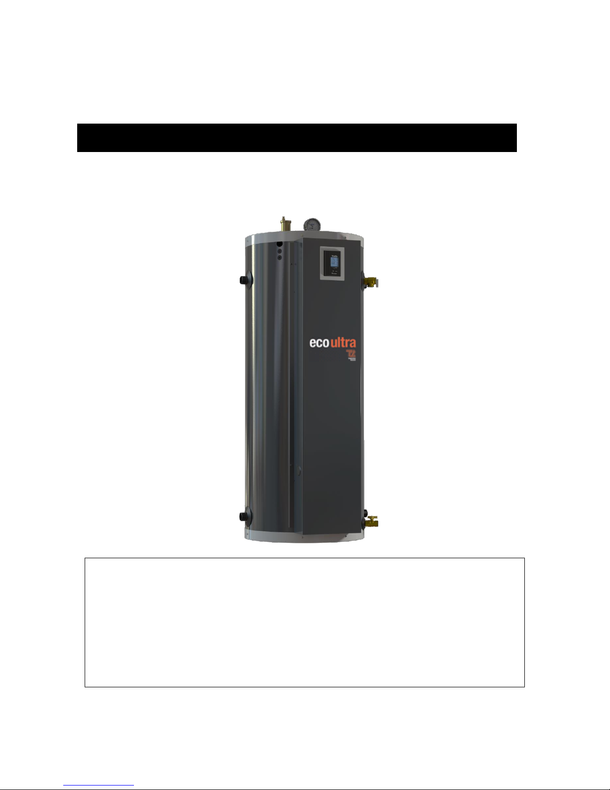
ECO ULTRA
Power capacity : 4.5 kW to 29 kW :
120V- 208/240V (single phase)
Your ECO ULTRA electric boiler has been carefully assembled and factory tested to provide
years of trouble-free service. This manual contains instructions for the safe and proper
installation, operation and maintenance of the boiler, in order to ensure your full satisfaction.
It is imperative that all persons who are expected to install, operate or adjust this boiler read
the instructions carefully.
Any questions regarding the operation, maintenance, service or warranty of this water heater
should be directed to the dealer or distributor you purchased it from. When all installation
steps have been completed, replace this installation manual in its original envelope, and keep
in a safe place near the heater for future reference.
Electric thermal mass boiler
INSTALLATION, USE AND CARE MANUAL
THERMO 2000 INC. Revision : June 2017
Printed in Canada

Table of contents
Section 1 : TECHNICAL SPECIFICATIONS ......................................................................................................................................... 3
1.1POWER AND DIMENSIONS ...................................................................................................................................................... 3
1.2 BUFFER TANK ......................................................................................................................................................................... 4
1.3 STORAGE TANK ...................................................................................................................................................................... 4
1.4 HYDRAULIC SEPARATOR ....................................................................................................................................................... 4
1.5 BACK UP BOILER ..................................................................................................................................................................... 4
1.5.1 Autonomous electrical mode ............................................................................................................................................. 4
1.5.2 Automatic transfer mode ................................................................................................................................................... 4
Section 2 : INTRODUCTION ................................................................................................................................................................ 5
2.1 LOCAL INSTALLATION REGULATIONS .................................................................................................................................. 5
2.2 CORROSIVE ATMOSPHERE ................................................................................................................................................... 5
2.3 SHIPMENT INSPECTION ......................................................................................................................................................... 5
2.4 TO VERIFY ............................................................................................................................................................................... 5
Section 3 : INSTALLATION .................................................................................................................................................................. 6
3.1 SAFETY MEASURES................................................................................................................................................................ 6
3.2 LOCATION ................................................................................................................................................................................ 6
3.3 CLEARANCES ................................................................................................................................................................ .......... 6
3.4 PIPING INSTALLATION ............................................................................................................................................................ 7
3.5 BOILER COMPONENTS ........................................................................................................................................................... 7
3.6 SYSTEM SETUP ..................................................................................................................................................................... 12
3.6.1 Connecting the boiler ...................................................................................................................................................... 12
3.6.2 Flow-check valve ............................................................................................................................................................. 12
3.6.3 Pressure relief valve ........................................................................................................................................................ 12
3.6.4 Expansion tank ................................................................................................................................................................ 12
3.6.5 Water pressure regulator ................................................................................................................................................. 12
3.6.6 Automatic Air Vent ........................................................................................................................................................... 12
3.6.7 Heating pump .................................................................................................................................................................. 13
3.7 BOILER WIRING: .................................................................................................................................................................... 13
3.7.1 Main power supply .......................................................................................................................................................... 13
3.7.2 Heating pump wiring ........................................................................................................................................................ 13
3.7.3 Outdoor temperature sensor ............................................................................................................................................ 13
3.7.4 Room thermostat wiring ................................................................................................................................................... 13
3.7.5 Automatic transfer mode wiring ...................................................................................................................................... 14
3.8 WIRING DIAGRAMS ............................................................................................................................................................... 16
Section 4 : ADJUSTMENT OF THE CONTROLLER ........................................................................................................................... 18
4.1 INTRODUCTION ..................................................................................................................................................................... 18
4.2 DISPLAYED INFORMATION ................................................................................................................................................... 18
4.3 OPERATION OF THE INTERFACE ........................................................................................................................................ 19
4.4 OPERATION IN “FIXED BOILER TEMPERATURE SET POINT” ............................................................................................ 19
4.5 OPERATION WITH “OUTDOOR RESET”: .............................................................................................................................. 19
4.6 PURGE DELAY OF THE PUMP .............................................................................................................................................. 20
4.7 AUTOMATIC HEATING SHUT DOWN .................................................................................................................................... 20
4.8 CONFIGURATION OF THE CONTROLLER ............................................................................................................................ 20
4.9 ADJUSTMENTS OF THE TARGET TEMPERATURE BY THE USER: .................................................................................... 22
4.10 BOOST SYSTEM OPERATION............................................................................................................................................. 22
4.11 OPERATION IN AUTOMATIC TRANSFER MODE: ............................................................................................................... 23
Section 5 : START UP OPERATION .................................................................................................................................................. 24
5.1 PREPARATORY STEP ........................................................................................................................................................... 24
5.2 STARTUP & INSPECTION ...................................................................................................................................................... 24
5.3 COMPLEMENTARY CHECKS ON AUTOMATIC TRANSFER MODE ..................................................................................... 24
Section 6 : MAINTENANCE ................................................................................................................................................................ 25
6.1 INTRODUCTION ..................................................................................................................................................................... 25
6.1 AT ALL TIMES ........................................................................................................................................................................ 25
6.2 EVERY 6 MONTHS ................................................................................................................................................................. 25
6.3 YEARLY INSPECTION ............................................................................................................................................................ 25
Section 7 : TROUBLE SHOOTING ..................................................................................................................................................... 26
7.1 TROUBLE SHOOTING TABLE................................................................................................................................................ 26
7.2 SPARE PARTS ....................................................................................................................................................................... 28
Section 8 : OPTION DHW HEAT EXCHANGER ................................................................................................................................. 31
ECO ULTRA LIMITED WARRANTY ................................................................................................................................................... 40
ECO ULTRA Electric Boiler Installation, Use and Care Manual (Revision June 2017), Page 2.
Model
ECO ULTRA
Power
(kW)
Heating
Elements
Amperage
2
Suggested
electrical
cable
at 240V
3
Suggested
Breaker/Fuse
at 240V
3
208 V
240V
208 V
240V
cu
al
4.5
3.4
4.5
1 x 4,5 kW
16.3
18.9
10
10
30
7.5
5.6
7.5
1 x 4.5 kW +
1 x 3 kW
27.2
31.2 8 6
40
9
6.8 9 2 x 4,5 kW
32.6
37.5 8 6
50
12
9
12
2 x 6 kW
43.5
50 6 4
70
15
11.2
15
2 x 3 kW +
2 x 4,5 kW
54.3
62.5 6 4
80
18
13.5
18
4 x 4,5 kW
65.2
75 4 2
100
20
15
20
4 x 5 kW
72.5
83.3 3 2
110
24
18
24
4 x 6 kW
87
100 2 0
125
27
4
20.3
27
6 x 4,5 kW
97.9
112.5
1
00
150
29
4
21.8
29
2 x 4,5 kW +
4 x 5 kW
104
120 1 00
175
ECO ULTRA 50
ECO ULTRA 70
Height
56-7/16’’
66-7/16’’
Diameter
22’’
24’’
Depth (with door)
25-1/2’’
28’’
Weight
280 lb
380 lb
Heating supply
1’’ NPTM
1-1/4’’ NPTM
Heating return
1’’ NPTM
1-1/4’’ NPTM
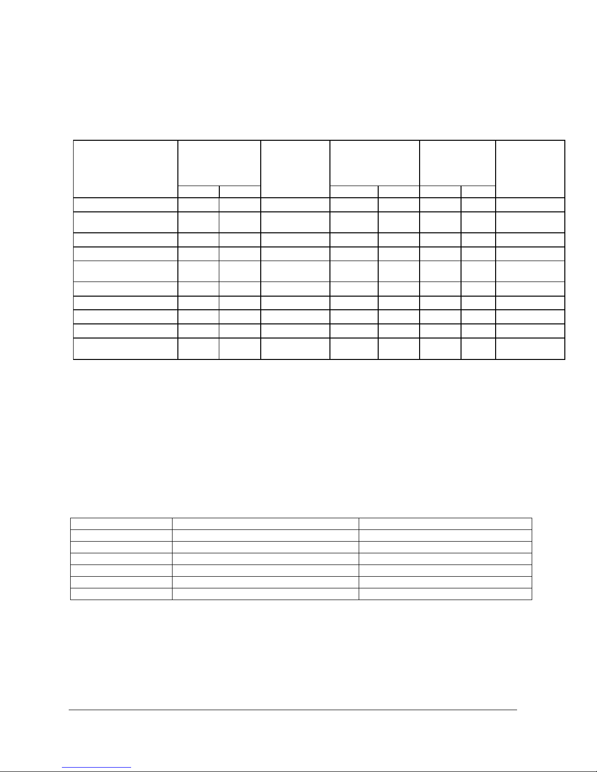
Section 1 : TECHNICAL SPECIFICATIONS
1.1 POWER AND DIMENSIONS
Table 1: Boiler specifications 208V/240V/1ph.1:
1
Electrical supply: 120/240V or 120/208V single-phase (L1 – N – L2) with three 90°C conductors, or two conductors
L1 – L2 if the boiler does not require power to a 120 VAC pump or accessories.
2
Add the amperage of the circulating pump and other external accessories if they are connected to the boiler (max.
5A).
3
A higher cable size could be required. In all cases the local electrical code has priority. The electrician has the
responsibility to select the appropriate size.
4
These models are only available on the ECO ULTRA 70.
Maximum operating pressure on the tank: 207 kPa / 30 psi
Tank temperature range : 10°C to 88°C (50°F to 190°F)
1 kW = 3412 BTU/h
Table 2: Dimensions:
ECO ULTRA Electric Boiler Installation, Use and Care Manual (Revision June 2017), Page 3.

1.2 BUFFER TANK
The ECO ULTRA boiler optimizes runtimes and
limits on/off cycling of the energy source(s).
When the minimum system load is lower than the
energy source’s minimum capacity, the system
will generate short cycles. This causes premature
wear of the equipment and substantially
decreases the system’s energy efficiency.
1.3 STORAGE TANK
Any hydronic heating system with the ECO
ULTRA stores energy like a battery. When a
demand is made for limited heating (for example,
when there is little difference between indoor and
outdoor temperatures) or when it is used with a
low-capacity energy source, the energy required
will first come from the tank’s thermal storage.
1.4 HYDRAULIC SEPARATOR
Adding an ECO ULTRA boiler to a hydronic
heating system helps to evacuate air, eliminates
impurities, and ensures the optimal functioning of
the pumps—not only for the energy source but
also for the distribution system.
1.5 BACK UP BOILER
The addition of an ECO ULTRA electric boiler to
a hydronic heating system acts as a back-up
source to the main renewable energy system.
The boiler can operate in two modes:
autonomous electrical mode or automatic
transfer mode.
For both modes, it is recommended to use the
outdoor sensor supplied with the equipment. The
outdoor sensor allows the boiler water
temperature to be modulated according to the
outside temperature. It also makes it possible to
stop the heating of the electric elements when the
outside temperature exceeds a certain
temperature. The use of these functions makes it
possible to optimize the start-up of the main
renewable energy system.
1.5.1 Autonomous electrical mode
By default, the boiler operates in autonomous
electrical mode where, on request of heat, the
ECO ULTRA boiler turns on the distribution
pump, reads the water temperature and activates
the electrical elements according to the
Parameters of the UltraSmart controller
independently if the main renewable energy
source is on or off.
In addition, for this mode, it is recommended to
adjust the setpoint of the renewable energy
source to a value greater than 10°F to 20°F than
the ECO ULTRA to reduce the start-up of the
electrical elements.
1.5.2 Automatic transfer mode
The boiler can also be operated in the automatic
transfer mode, where the ECO ULTRA electric
boiler turns on the distribution pump, reads the
water temperature and activates the electrical
elements if authorized by an external signal. The
elements are then switched on according to the
adjustment parameters of the UltraSmart
controller.
ECO ULTRA Electric Boiler Installation, Use and Care Manual (Revision June 2017), Page 4.
!
WARNING
!
WARNING
!
General Safety Precautions
Be sure to read and understand the entire Manual before attempting to install or operate
this unit. Pay particular attention to the following General Safety Precautions. Failure to
follow these warnings could cause property damage, bodily injury or death. Should you
have any problems understanding the instructions in this manual, STOP, and get help
from a qualified installer or technician.
Section 2 : INTRODUCTION
The important safeguards and instructions
appearing in this manual are not meant to
cover all possible conditions and situations
that may occur. It should be understood that
common sense, caution and care are factors
which cannot be built into every product.
These factors must be supplied by the
person(s) caring for and operating the unit.
2.1 LOCAL INSTALLATION
REGULATIONS
This ECO ULTRA electric boiler must be installed
in accordance with these instructions and must
conform to local regulation, or in the absence of
local codes, with the current edition of the
National Plumbing Code and the National Electric
Code. In any case where instructions in this
manual differ from local or national codes, the
local or national codes take precedence.
2.2 CORROSIVE ATMOSPHERE
The electric boiler should not be located near an
air supply containing halogenated hydrocarbons
or high humidity. The limited warranty is voided
when failure of the water heater is due to a
corrosive atmosphere.
2.3 SHIPMENT INSPECTION
Inspect the electric boiler for possible shipping
damage. The manufacturer’s responsibility
ceases upon delivery of goods to the carrier in
good condition. Consignee must file any claims
for damage, shortage in shipments, or nondelivery immediately against carrier.
2.4 TO VERIFY
Please check the boiler identification plate to
ensure you have the right model.
The following items are factory installed and
shipped with the unit:
207 kPa (30 psi) tank pressure relief
valve.
Tank drain valve
Thermo manometer (heat and
pressure indicator).
Automatic air vent.
Electric heating elements
ULTRA SMART™ controller.
The ECO ULTRA electric boiler should not be
located in an area where leakage from the tank
or water connections will result in damage to
the adjacent area or to lower floors of the
structure. When such areas cannot be
avoided, a suitable drain pan or nonflammable catch pan, adequately drained,
must be installed under the boiler. The pan
must be connected to a drain.
ECO ULTRA Electric Boiler Installation, Use and Care Manual (Revision June 2017), Page 5.
Left side
0 mm/ 0 ‘’
Right side
0 mm/ 0 ‘’
Top
127 mm / 5 ’’
Front*
75 mm / 3 ’’
Back
0 mm/ 0 ‘’
WARNING
!
Section 3 : INSTALLATION
The manufacturer’s warranty does not cover
any damage or defect caused by installation
or attachment or use of any special
attachment other than those authorized by the
manufacturer into, onto, or in conjunction
with the water heater. The use of such
unauthorized devices may shorten the life of
the water heater and may endanger life and
property. The manufacturer disclaims any
responsibility for such loss or injury resulting
from the use of such unauthorized devices.
3.1 SAFETY MEASURES
All installations will include a pressure relief valve
limiting the operating pressure to 207 kPa (30
psi).
This ECO ULTRA electric boiler is designed for a
maximum operating temperature of 88°C
(190°F). It is designed for hot water heating
systems only. When allowed by local regulation a
maximum 50% blend of water and antifreeze (
designed specifically for water heating systems)
may be used.
The boiler is equipped with an automatic high limit
temperature control set at 210°F (99°C) and
models sale in USA have a second limit device
manually re-settable set at 227°F (108°C). If the
heating distribution system on which the boiler is
installed requires a high limit controller having a
lower setting, this controller will be added to the
system and connected in series with the factory
installed limit control.
3.2 LOCATION
The ECO ULTRA boiler should be installed in a
clean, dry location. Long hot water lines should
be insulated to conserve energy. The boiler and
piping should be protected from exposure to
freezing.
The ECO ULTRA boiler must be installed levelled
and vertically. Adjustable legs allow for levelling
and stability.
The ECO ULTRA boiler must be located or
protected so as not to be subject to physical
damage, for example, by moving vehicles, area
flooding, etc.
All models can be installed on combustible floors
and in alcoves.
3.3 CLEARANCES
The minimal clearances required for proper
inspection and servicing are as follows.
Supplementary clearances could be required for
piping installation.
Table 3: Minimum clearances required
*If the installation is inside a closet with an access
door, ventilation openings could be required to
maintain the ambient temperature below 32°C
(90°F).
ECO ULTRA Electric Boiler Installation, Use and Care Manual (Revision June 2017), Page 6.
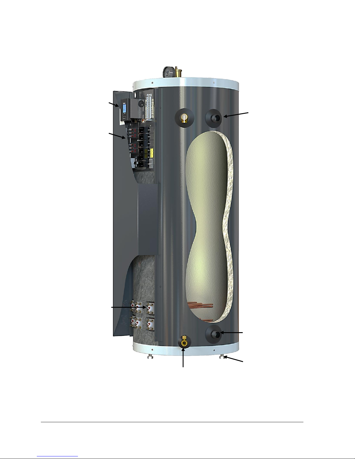
Pressure relief valve (30 psi)
Automatic air vent
Temperature and pressure
indicator
Main Electrical Supply
Low voltage
connections
Heating supply
Model 50: 1” NPTM
Model 70: 1 ¼“ NPTM
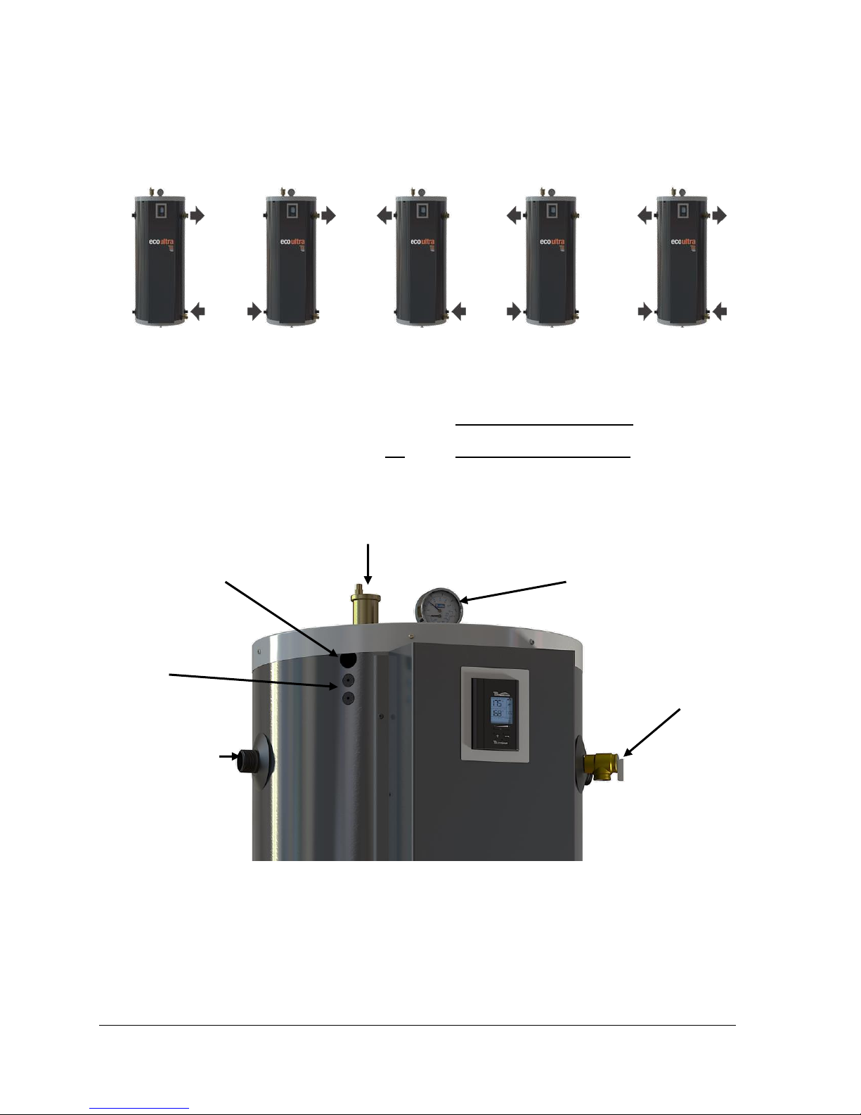
3.4 PIPING INSTALLATION
Make sure that the installation complies with one
of the configuration shown below and that the
water circulation is done in the right way.
Figure 1: Possible installation configurations
3.5 BOILER COMPONENTS
Figures 2 and 3 show various components of the
ECO ULTRA electric boiler. Figures 4 and 6 show
some installation drawings of the boiler in the
autonomous electrical mode. Figures 5, 7 and 8
show some installation drawings of the boiler in
the automatic transfer mode.
Figure 2 : Components identification and location (top right side view)
ECO ULTRA Electric Boiler Installation, Use and Care Manual (Revision June 2017), Page 7.
Adjustable feet
UltraSmart controller
Heating elements
Heating return
Model 50: 1” NPTM
Model 70: 1 ¼“ NPTM
Electrical components
mounting panel
Drain valve
Heating supply
Model 50: 1” NPTM
Model 70: 1 ¼“ NPTM
Figure 3: Components identification and location (left side view)
ECO ULTRA Electric Boiler Installation, Use and Care Manual (Revision June 2017), Page 8.
RA89
34
21
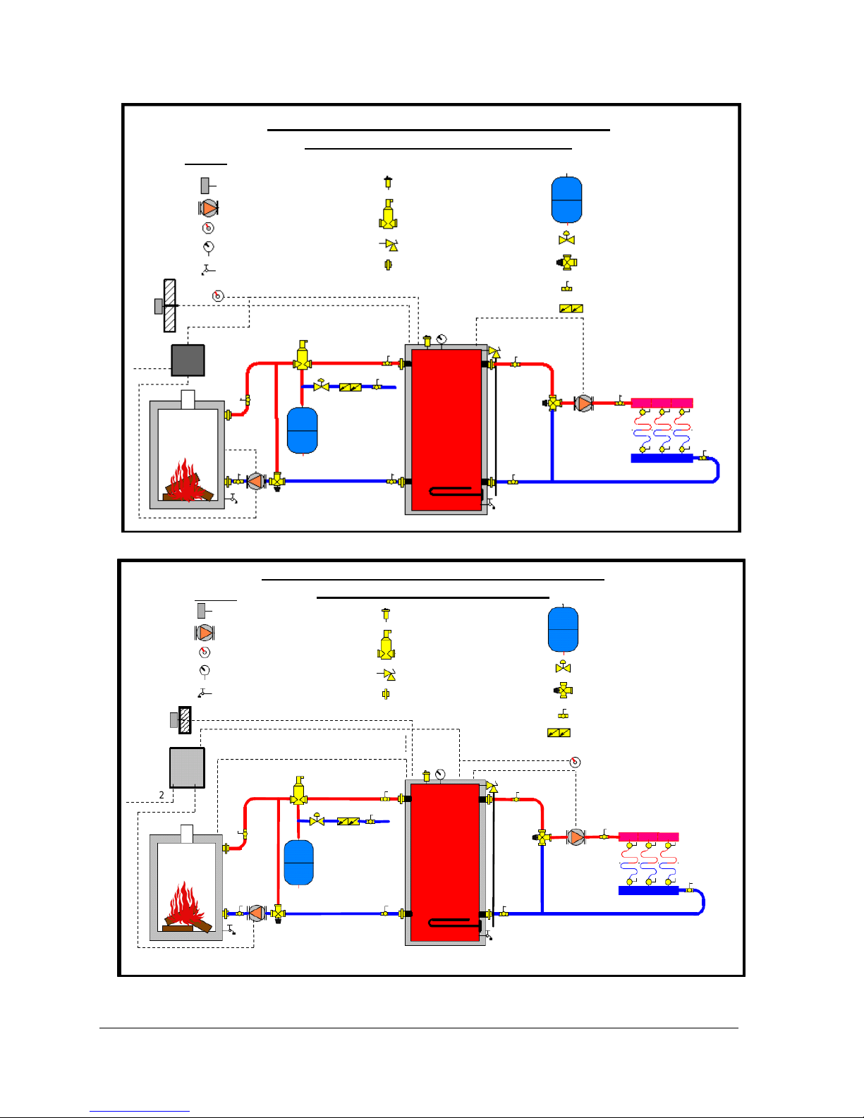
ECO ULTRA INSTALLED WITH WOOD BOILER
AUTOMATIC TRANSFER MODE
Legend
Outdoor sensor
Circulating pump
Room thermostat
Pressure and temperature
indicator
Drain valve
Automatic air vent
Air seperaor
Service valve
Pressure relief valve
Union
Expansion tank
Pressure regulator
Thermostatic mixing
Chaudière au bois
ECO ULTRA
Back flow preventor
TT
120 V
EE
ECO ULTRA INSTALLED WITH WOOD BOILER
Legend
Outdoor sensor
Circulating pump
Room thermostat
Pressure and temperature
indicator
Drain valve
Automatic air vent
Air seperaor
Service valve
Pressure relief valve
Union
Expansion tank
Pressure regulator
Thermostatic mixing valve
Wood boiler
ECO ULTRA
Back flow preventor
AUTONOMOUS ELECTRICAL MODE
Figure 4: Basic dual energy Installation drawing for radiant floor.
valve
Figure 5: Dual energy Installation drawing for radiant floor and wood boiler.
ECO ULTRA Electric Boiler Installation, Use and Care Manual (Revision June 2017), Page 9.

ECO ULTRA INSTALLED WITH AIR-TO-WATER HEAT PUMP
AUTONOMOUS ELECTRICALMODE
Legend
Outdoor sensor
Circulating pump
Room thermostat
Pressure and temperature
indicator
Drain valve
Automatic air vent
Air seperaor
Service valve
Pressure relief valve
Union
Expansion tank
Pressure regulator
Thermostatic mixing
Air-to-water heat pump
ECO ULTRA
Back flow preventor
EE
ECO ULTRA INSTALLED WITH AIR-TO-WATER HEAT PUMP
AUTOMATIC TRANSFER MODE
Legend
Outdoor sensor
Circulating pump
Room thermostat
Pressure and temperature
indicator
Drain valve
Automatic air vent
Air seperaor
Service valve
Pressure relief valve
Union
Expansion tank
Pressure regulator
Thermostatic mixing
Air-to-water heat pump
ECO ULTRA
Back flow preventor
valve
Figure 6: Basic dual energy Installation drawing for radiant floor and Air-to-water heat pump
valve
Figure 7: Dual energy Installation drawing for radiant floor and Air-to-water heat pump
ECO ULTRA Electric Boiler Installation, Use and Care Manual (Revision June 2017), Page 10.

Diverter valve
ECO ULTRA INSTALLED WITH AIR-TO-WATER HEAT PUMP
Legend
Outdoor sensor
Circulating pump
Room thermostat
Pressure and temperature
indicator
Drain valve
Éliminateur d’air automatique
Air seperaor
Service valve
Pressure relief valve
Union
Expansion tank
Pressure regulator
Thermostatic mixing
Air-to-water heat pump
ECO ULTRA
Back flow preventor
Cooling system
EE
AUTOMATIC TRANSFER MODE
valve
Figure 8: Dual energy Installation drawing for radiant floor and Air-to-water heat pump
ECO ULTRA Electric Boiler Installation, Use and Care Manual (Revision June 2017), Page 11.

ECO ULTRA
Baseboards
Radiant
floor
Cast-iron
radiators
ECO ULTRA 50
#30
#30
#60
ECO ULTRA 70
#60
#60
#90
3.6 SYSTEM SETUP
Figures 2 to 8 indentify and show location of the
different components. They also provide typical
heating system installation. External components
location may vary in order to accommodate
specific installation and local codes and
regulation.
3.6.1 Connecting the boiler
The boiler heating supply and return connections
are located on the left or right side and are 1”
NPTM for Model 50 and 1-¼’’ NPTM for model
70. The connections at the left or right can be
used. The important thing is that the fluid
circulation must be made from the bottom to the
top (see figure 1)
Unions are recommended on the inlet and outlet
pipes to disconnect the water heater easily for
servicing if necessary.
Dielectric (insulating) unions should be used if
copper-steel connections are made.
Insulate all pipes containing hot water, especially
in unheated areas.
3.6.2 Flow-check valve
If the heating system uses a single or multiple
circulators without motorized zone valves, a flow-
check valve must be installed to avoid all
possibility of gravity flow and heat loss during
non-draw periods. Modern circulators are
typically provided with spring loaded check valves
that will provide adequate protection.
If the heating system uses motorized zone
valves, these will provide adequate protection.
3.6.3 Pressure relief valve
The boiler is delivered with a factory installed tank
pressure relief valve set at 207 kPa (30 psi).
NEVER replace the pressure relief valve by a
higher set pressure one.
Connect the outlet of the relief valve downward
toward a safe location.
Relief valve outlet pipe diameter must not be of
smaller diameter than the relief valve outlet. The
oulet pipe end must be visible in order to observe
any relief incident and be protected from freezing.
NEVER cap or plug a pressure relief valve
outlet. The pressure relief valve is a safety
apparatus and preventing its proper operation
may cause death, injury or property damage.
3.6.4 Expansion tank
When operating the ECO ULTRA and the heating
system, pressure will vary between 83 kPa and
193 kPa (12 psi to 28 psi). The operating
pressure is affected by the type of heating system
and the size of the expansion tank installed.
The expansion tank is used to absorb the
increase of water volume from the boiler and the
system when it is working.
The model selection should be based on the
maximum working temperature and the water
volume of the total system. For example, a
system with radiators contains much more water
volume than a baseboards system. Likewise, the
ECO ULTRA also contains an important volume
of water that has to be added :
ECO ULTRA 50 : 48 usgal
ECO ULTRA 70 : 71 usgal
With this information, the installator or distributor
should be able to make an appropriate selection
for an expansion tank.
Here are some minimal recommendations for
different types of heating systems.
The expansion tank is generally installed on the
wall or ceiling. It also has to be well supported.
3.6.5 Water pressure regulator
The boiler should be installed in such a way that
it can automatically be fed with water in the event
of a pressure drop.
The minimum pressure obtained when the
system is cold is generally 12 psi (83 kPa).
This accessory shall be equipped with one or
more check valves to avoid all possibilities of the
boiler water returning to the potable water supply
network (local regulation should be applied)
3.6.6 Automatic Air Vent
The ECO ULTRA has a factory installed tank
automatic air vent. This air vent function is to vent
any air present in the tank.
For proper operation, do not cap or block the air
bleeder outlet.
For proper operation of the heating system, it may
be necessary to add air bleeders to the heating
system circuits.
ECO ULTRA Electric Boiler Installation, Use and Care Manual (Revision June 2017), Page 12.

3.6.7 Heating pump
A circulating pump (not included) is required for
the heating system to deliver heating fluid to the
different heating zones. Sizing of the pump is
base on the heating system configuration and is
done by the installator (heating technician,
plumber).
3.7 BOILER WIRING:
3.7.1 Main power supply
The electrical wiring and grounding must conform
to local codes or, in their absence, to the National
Electrical Code. Local codes have authority for
wiring and electric breaker sizing. It is the
electrical technician responsibility to insure that
the installation meets the applicable codes
requirements.
On installation where a 120 Vac power is required
for a heating pump and other outboard
components, main power supply to the ECO
ULTRA must be a 120/240 Vac, single phase, 60
Hz using 3 conductors (L1 – L2 – N) and a ground
wire.
On installation where no 120 volts external
components need to be powered by the ECO
ULTRA, Power supply could then be supplied
with only two conductors L1-L2 with a ground
wire.
Electrical current draw for the boiler being
installed is indicated on the boiler’s name plate.
The electrical technician needs this information in
order to determine the proper electrical breaker
and cable. The cable can be either aluminum or
copper, but must be adequate for 75°C operation.
If aluminum cables are used, it shall be of an
adequate size (generally bigger) and particular
consideration will have to be respected such as
the use of DE-OX inhibitors in order to meet the
National electrical code.
3.7.2 Heating pump wiring
If the building heating system is designed for a
single pump operation and the electrical power to
the boiler is 120/240 Vac 3 conductors and
ground type, the pump (1/6 HP max) can be
directly connected to the boiler electric panel “PP”
terminals. The boiler control will operate the
pump as soon as a heat demand is signalled by
the space thermostat.
3.7.3 Outdoor temperature sensor
If you want the boiler target temperature to
modulate according to the outdoor temperature
(when the outdoor temp. will get colder, the target
temperature will get higher). The supplied
outdoor sensor will have to be connected to S1
S1 before turning the power on to the unit.
The installation of this sensor cancels the
operation of the boiler when the outdoor
temperature exceeds the selected value
corresponding to the maximum temperature
required for heating.
This control strategy optimize the use of the main
renewable energy source by reducing the use of
electric elements of the ECO ULTRA boiler.
1. Sensor location:
-Outside the building at a location which best
represents the heat demand of the building (a
wall facing north for most of the buildings and on
a south one on buildings with large windows
facing south).
-It should not be exposed to external heat
sources (dryer outlet, window openings,
uninsulated walls).
-It should not be installed in a location where it
could be covered with snow.
2. Installation:
-Drill a 9/64” dia. hole through the wall and insert
the sensor cable.
-Fix the sensor cover to the wall using supplied
screw.
-With an electric cable (100ft max.) having 2
conductors 20ga. connect one end of this cable
to the sensor cable using twist-on wire
connectors and the other end to terminals S1 &
S1 of the boiler.
If you wish to operate the boiler at a fixed target
temperature, simply do not connect the sensor
before applying the power to the unit (do not put
a jumper between S1&S1 if the outdoor sensor is
not used).
3.7.4 Room thermostat wiring
3.7.4.1 Single heating zone
Using a two (2) wires central thermostat, connect
the low-voltage thermostat dry contact to the W
and R terminals on the ECO ULTRA electrical
panel.
Using a three (3) wires central thermostat,
connect the C, W and R terminals to the boiler
electric panel corresponding terminals.
ECO ULTRA Electric Boiler Installation, Use and Care Manual (Revision June 2017), Page 13.

ECO ULTRA
DO NOT apply external current to these
terminals.
3.7.4.2 Zone valve zoning
Connect the low-voltage thermostat to the zone
valve motor. The components must wired such
that, upon a heating demand from a thermostat,
only the corresponding zone valve will be
actuated and will in turn activate the ECO
ULTRA. Connect the zone valve dry end switch
contact to the W and R boiler electrical panel
terminals
The 24 Vac power supply transformer used
must be powerful enough to supply
simultaneously all zone valves.
3.7.5 Automatic transfer mode wiring
If needed, The ECO ULTRA boiler is designed to
automatically transfer the right energy source to
be in function. The automatic transfer mode is not
set by default. This mode allows to activate the
electric elements upon reception of an external
signal. The ECO ULTRA will select the
appropriate energy source and will activate the
renewable energy source or the electic boiler. If
the heating distribution system is equipped with a
single pump connected to the PP terminals of the
boiler, it will be activated on heat calls from the
thermostat, whichever the energy source
selected.
To allow the operation in automatic transfer
mode:
Open the front access panel to the boiler
electric compartment. Remove the screw at
the bottom of the controller; raise the upper
section of the controller. You will see a
switch at the back of the controller having
two positions “ELECT” and “Bi-Energ”.
Position the switch at “Bi-Energ” (see fig.9)
Install a 2 wire 18ga cable between the
contact (NC contact to allow the operation in
electricity) of the external device making the
selection of the operating mode and
terminals E1 E2 (see fig.10)
Install a pump relay (such as Honeywell
RA832 or TACO SR501-4) near the
renewable energy source to authorize the
ECO ULTRA control the start up your
renewable energy source. (see fig.10)
- The relay can be supplied by an external
120V source or directly from the boiler fuse
and P2 neutral.
- Install a 2 wire 18 gauge cable between the
“AUX” of the ECO ULTRA and “TT” of the
relay RA832 (or R and W of relay TACO
501-4)
- Connect the auxiliary pump wires on the
relay terminals.
- Connect the electric terminal of the
renewable energy on the “XX” relay RA832
terminals or 6-5 of the relay TACO 501-4
(see fig.10)
- The renewable energy source must be be
controlled by its own operation and limiting
controller.
Do not connect the main electrical supply
of the renewable energy source to AUX
terminals.
Figure 9: Back of the Controller
ECO ULTRA Electric Boiler Installation, Use and Care Manual (Revision June 2017), Page 14.

External signal
Figure 10: Wiring diagram with auxiliary energy source
It is also possible to allow the renewable energy
source to be operated according to its own
controls at all times (do not use the ECO ULTRA
contact of the "AUX" terminals) and when the
main renewable energy source is not sufficient to
the request, (closed contact between E1 & E2)
the heating elements will be activated according
to the operating parameters of the controller.
ECO ULTRA Electric Boiler Installation, Use and Care Manual (Revision June 2017), Page 15.

3.8 WIRING DIAGRAMS
ECO ULTRA Electric Boiler Installation, Use and Care Manual (Revision June 2017), Page 16.

ECO ULTRA Electric Boiler Installation, Use and Care Manual (Revision June 2017), Page 17.

Section 4 : ADJUSTMENT OF THE CONTROLLER
4.1 INTRODUCTION
The ECO ULTRA boiler is mainly designed to be
installed on closed circuit applications where the
water of the heating system flows directly from
the boiler to the heating distribution system
(Standard parallel Piping system)
Two operation modes are then offered:
Fixed boiler temperature set point (the
outdoor sensor shall not be installed)
Or
Outdoor reset
4.2 DISPLAYED INFORMATION
The electronic control uses an LCD display to
make all adjustments and to visualize the
operation of the system.
ECO ULTRA Electric Boiler Installation, Use and Care Manual (Revision June 2017), Page 18.
Figure 11 : UltraSmart Controller Display

4.3 OPERATION OF THE INTERFACE
The controller uses four push buttons at the
bottom of the display to select and adjust the
parameters.
The button is used to access the
configuration menu and confirm a selection.
The buttons are used to select
an item or adjust a value.
The button enables the illumination of the
display under two different modes.
The default mode will enable the illumination of
the display for a period of 10 sec. each time a
button is pressed. If the is pushed, the light will
be continuously illuminated. Just press the button
to change the mode of activation.
4.4 OPERATION IN “FIXED BOILER
TEMPERATURE SET POINT”
For installation where the boiler target
temperature shall be maintained at a fixed
temperature that will not vary in relation to the
outdoor temperature, the sequence of operation
will be as follow:
On a call for heat from the room thermostat, the
circulating pump will start and the boiler will
activate the number of stages required to get to
and maintain the outlet temperature of the boiler
near the selected target temperature. A rotation
of the stages based on an equal time period of
operation is provided.
N.B. The supplied outdoor temperature sensor
shall not be connected before applying the
electrical power to the unit
4.5 OPERATION WITH “OUTDOOR
RESET”:
For installation where the boiler target
temperature shall modulate in relation to the
outdoor temperature; when the outdoor
temperature gets colder, the boiler target
temperature will increase.
On a call from the room thermostat, the
circulating pump will start and the boiler will
activate the number of stages required to get to
and maintain the outlet boiler temperature near
the target temperature established by the
controller according to the outdoor temperature.
A rotation of the stages based on an equal time
period of operation is provided.
Figure 12 : UltraSmart Control Module
N.B. The supplied outdoor temperature sensor
must be connected before applying the electrical
power to the unit.
The boiler target temperature will be calculated
by the controller in relation to the parameters
selected in the menu
and the
maximum target temperature required when the
outdoor temperature will get to -10°F (-23°C). The
“STD” curve corresponds to the default maximum
temperature for a typical system and this value
can be modified from the “MIN” to “MAX” value
shown on the following tables.
ECO ULTRA Electric Boiler Installation, Use and Care Manual (Revision June 2017), Page 19.

80F
27C
70F
21C
60F
15C
50F
10C
10F
-12C
40F4C30F0C20F
-7C
0F
-17C
-10F
-23C
-20F
-29C
110F/43C
120F/49C
130F/54C
Température ext. / Outdoor temperature
Temp. de consigne / Target temp.
STD
MAX
MIN
PLINTHES CHAUFFANTES À AILLETTES
FINNED-TUBE HOT WATER BASEBOARDS
140F/60C
150F/65C
160F/71C
170F/77C
180F/82C
190F/88C
80F
27C
70F
21C
60F
15C
50F
10C
10F
-12C
40F4C30F0C20F
-7C
0F
-17C
-10F
-23C
-20F
-29C
70F/21C
80F/27C
100F/-38C
90F/32C
110F/43C
120F/49C
130F/54C
Température ext. / Outdoor temperature
Temp. de consigne / Target temp.
STD
MAX
MIN
PLANCHER CHAUFFANT DANS BÉTON
RADIANT FLOOR IN CONCRETE
80F
27C
70F
21C
60F
15C
50F
10C
10F
-12C
40F4C30F0C20F
-7C
0F
-17C
-10F
-23C
-20F
-29C
100F/-38C
90F/32C
110F/43C
120F/49C
130F/54C
Température ext. / Outdoor temperature
Temp. de consigne / Target temp.
STD
MAX
MIN
PLANCHER CHAUFFANT ENTRE SOLIVES
RADIANT FLOOR BETWEEN JOISTS
140F/60C
80F/27C
80F
27C
70F
21C
60F
15C
50F
10C
10F
-12C
40F4C30F0C20F
-7C
0F
-17C
-10F
-23C
-20F
-29C
100F/-38C
90F/32C
110F/43C
120F/49C
130F/54C
Température ext. / Outdoor temperature
Temp. de consigne / Target temp.
STD
MAX
MIN
RADIATEURS EN FONTE
CAST IRON RADIATORS
140F/60C
150F/65C
160F/71C
170F/77C
The following tables show the values of the target
temperature that will be obtained in relation to the
outdoor temperature.
ECO ULTRA Electric Boiler Installation, Use and Care Manual (Revision April 2017), Page 20.
4.6 PURGE DELAY OF THE PUMP
The controller offers the possibility to
stop the operation of the pump after an adjustable delay
once the heat demand has been completed.
The following choices are offered:
“OFF” The pump will stop immediately when the
heat demand has been satisfied. This selection
shall be selected on systems equipped with
motorised fast closing zone valves in order to
prevent noise from water hammering.
“15 sec to 60 min” delay where the pump will be
kept running to enable the pump to circulate
water into the system to equilibrate the heat in all
the building.
“ON” The pump is in continuous operation.
Required on particular heating distribution
systems.
4.7 AUTOMATIC HEATING
SHUT DOWN
When the outdoor sensor is installed and the unit then
operates in the “outdoor reset” mode, the controller offers
the user the possibility to automatically stop the boiler
when the outdoor temperature reaches an adjustable
value (0°F (-17°C) à 105°F (40°C). This characteristic is
especially interesting on the following applications:
-Heating systems equipped with many thermostats
where the user wants to prevent the operation of the unit
if one of the thermostats has inadvertently been
activated.
-Heating systems where the owner supplies heat to a
lodger
-Systems connected to a geothermic or air-water
heat pump where we do not want the electric boiler
to be operating unless the outdoor temperature
drops to a selected degree.
4.8 CONFIGURATION OF THE CONTROLLER
Since each type of heating distribution system is
designed to operate at water temperatures that are
particular to its operation, the proper configuration of the
operating parameters of this particular system is
important to maximize its performance.
In order to do this, the installer will first have to tell the
controller if the application is in automatic transfer mode
or autonomous electric mode. The selection is made by
selecting the position “Elect.” for the autonomous electric
mode Or “Bi-Energ” for the automatic transfer mode on
the switch located at the back of the controller. This
selection will have to be made before applying voltage to
the unit. The default setting is the autonomous electric
mode “Elect.”

ITEM
DESCRIPTION
RANGE
DEFAULT
Choose the units the user prefers to work with
°F or °C
°F
Select the type of heating system on which the
boiler will be installed.
-Radiant Floor in
concrete
-Radiant Floor between
joists
-Cast iron radiator
-Hot water baseboards
Adjust the maximum boiler target temperature
required to adequately heat the building when the
outdoor temperature is very cold.
It is recommended to adjust the setpoint of the
renewable energy source to a value greater than
10 ° F to 20 ° F to the one of the ECO ULTRA to
reduce the start-up of the electrical elements, more
particularly when the autonomous electric mode is
used.
-Radiant Floor in
concrete
85°F to 105°F
-Radiant Floor between
joists 110°F to 140°F
-Cast iron radiator 135°F
to 165°F
-Baseboard
160°F to 185°F
100°F
125°F
150°F
175°F
This being done, the installer will have to access the
configuration menu by pressing the button for 2
sec. until the first menu appears. The selection of the
item or value is made by pressing the
button and by pressing the button to get to the
next menu. See table 1 below to visualize the menu list
that will gradually be displayed.
If the buttons remain untouched for a period of 10 sec.,
the controller will register the value of the selection made
and return to the regular display position. It will also
return to the regular display after reviewing all the
operating parameters of the controller.
In case of a power failure, the parameters will be restored
Figure 13 : Back of the controller
as they were established before the failure.
Table 5 below shows the presentation sequence of the
menus.
Table 6: CONFIGURATION SEQUENCE OF THE MENU (Press on the button for 2 seconds)
ECO ULTRA Electric Boiler Installation, Use and Care Manual (Revision June 2017), Page 21.

Select the purge period that the pump will be
running once the heat demand is completed.
Select OFF if the heat system is equipped with
electric zone valves.
OFF
15 sec. to 60min.
ON
30sec
Select the outdoor temperature at which no
heating of the building is required or the outdoor
temperature at which you allow the electrical
elements to be in function as a backup to your
main system. (the outdoor sensor has to be
installed)
0°F à 105°F
75°F
80F
27C
70F
21C
60F
15C
50F
10C
10F
-12C
40F4C30F0C20F
-7C
0F
-17C
-10F
-23C
-20F
-29C
70F/21C
80F/27C
100F/-38C
90F/32C
110F/43C
120F/49C
130F/54C
Température ext. / Outdoor temperature
Temp. de consigne / Target temp.
NORMAL
BOOST
maximum
HAUSSE AUTOMATIQUE DU POINT DE CONSIGNE
« BOOST »
AUTOMATIC INCREASE OF TARGET TEMPERATURE
80F
27C
70F
21C
60F
15C
50F
10C
10F
-12C
40F4C30F0C20F
-7C
0F
-17C
-10F
-23C
-20F
-29C
70F/21C
80F/27C
100F/-38C
90F/32C
110F/43C
120F/49C
130F/54C
Température ext. / Outdoor temperature
Temp. de consigne / Target temp.
NORMAL
Offset max
.
FONCTIONNEMENT DES TOUCHES
Offset min
.
Note 1: Once the operating parameters have been set, the controller will automatically come back to normal
display screen. If the user needs to increase or decrease the target temperature, he can do it without having
to enter in the configuration menu (see the following section).
4.9 ADJUSTMENTS OF THE TARGET
TEMPERATURE BY THE USER:
By pressing the button, the end
user has the possibility to offset the programmed target
temperature without going through the tool menus.
When the + or - button is pressed, the value “0” will
appear and blink to show a “0” offset value from the
original settings. When the + or - buttons are pressed
again the offset value will change up to a value of ± 10°F
(5°C) from the original setting made in the configuration
menu. The new value will blink during 5 sec. and the
display will then go back to the standard view and the
new target temperature will be shown.
Afterward, when the button will be
pressed, it will show the value of the offset made
previously and can be re-adjusted.
4.10 BOOST SYSTEM OPERATION
The controller incorporates a unique feature that enables
the target boiler temperature to automatically be
increased when the building heat load increases but
cannot be fulfilled with the actual boiler target
temperature and consequently the room thermostat(s)
cannot be satisfied within a pre-determined period.
Example:
-Return to normal heat load after low demand periods
occurring during sunny days.
OPERATION OF THE + - BUTTONS
ECO ULTRA Electric Boiler Installation, Use and Care Manual (Revision June 2017), Page 22.
-Long periods without heating which needs higher boiler
temperature to recuperate.
-Return to normal room temperature after thermostat’s
“night set back” program.
Three “Boost” operating options are available when the
is pressed for 6 sec. The icon will appear and
the three options ON1, ON2 and OFF will be proposed.
Press the button to select. The
controller will register the selected item and will return to
normal operation after 5 sec.
Operation in “Boost” Option ON1 (default setting)
The controller will engage the “Boost” program when the
heat demand on terminals RW has been maintained for
a pre-determined period according to the type of selected
application. Once this period has been reached, the
“Boost” icon will appear on the display and the boiler
target temperature will start increasing very slowly over
a pre-determined period and up to a pre-calculated
maximum value until the heat demand applied on RW
terminals has been completed.
On a new heat demand, the previous boost period is
forgotten and the boiler target gets back to its original
setting
Operation in “Boost” Option ON2 (only offered on
installation not operating in Dual-energy)
The boost program is a marvellous feature that works
fine on applications where the number of room
thermostats is in limited quantity otherwise it may happen
that during very cold periods the heat demand from all
the thermostats may not become satisfied.
This option requires the installation of one or two stages
heating thermostats. The second stage of the
thermostat(s) will have to be connected to E1-E2 of the
boiler and the option ON2 selected.
Then the Boost mode will be instantaneously started
increasing the target temperature when the signal from

80F
27C
70F
21C
60F
15C
50F
10C
10F
-12C
40F4C30F0C20F
-7C
0F
-17C
-10F
-23C
-20F
-29C
70F/21C
80F/27C
100F/-38C
90F/32C
110F/43C
120F/49C
130F/54C
Température ext. / Outdoor temperature
Temp. de consigne / Target temp.
NORMAL
BOOST
HAUSSE AUTOMATIQUE DU POINT DE CONSIGNE
« BOOST »
AUTOMATIC INCREASE OF TARGET TEMPERATURE
the second heating stage will be received. The target
temperature will immediately start increasing.
N.B. If the system is in “boost” most of the time, this
means that the boiler target parameter established
during “Setting procedure” would be too low for the
heating system on which the unit is applied. This boiler
target could simply be gradually increased by pressing
the + button or by re-setting the operating parameters
using the tool menus .
The Boost menu can be cancelled by selecting “OFF” in
the Boost menu.
4.11 OPERATION IN AUTOMATIC TRANSFER
MODE:
In automatic transfer mode, the display will indicate that
this mode is active in showing the icon
Upon reception of a heat demand on terminals R W of
the ECO ULTRA boiler, terminals P1&P2 will be
energized at 120volts and the pump will be activated. At
the same time, the contact will close on the “AUX”
terminals to activate the auxiliary boiler. This boiler will
be activated only when there will be a heat demand to
the R W terminals and when the auxiliary boiler
temperature will be lower than the settings of its own
temperature controls.
Using the "AUX" terminals on the ECO ULTRA to allow
the start-up of the renewable energy source, you operate
either with the renewable energy source or with
electricity.
It is also possible to allow the renewable energy source
to be operated according to its own controls at all times
(do not use the contact of the "AUX" terminals) and when
the latter is not sufficient to the request, (closed contact
between E1 & E2) the heating elements will be activated
according to the operating parameters established
previously.
Manual selection for the electricity or renewable
energy source.
If the user wishes to manually select the electricity or
renewable energy source, it can be done in following the
sequence below:
o Push on the button for 6 sec. and the
If it is not shown, check the position of the switch located
at the back of the controller. It must be set to “Bi-Energ”
position.
N.B. The controller will have to be reset to register the
new mode of operation. Just turn the power OFF and
back ON to the unit.
Operation in automatic transfer mode with Electric
Boiler
When the authorisation signal to operate in electricity is
received, (closed contact between E1 & E2), the following
icons will be shown.
The circulating pump and the heating elements will be
activated according to the operating parameters
established earlier.
Operation in automatic transfer mode with
Renewable energy source
When the authorisation signal will be absent (open
contact between E1&E2), the following icons will be
shown.
ECO ULTRA Electric Boiler Installation, Use and Care Manual (Revision June 2017), Page 23.
following icons will appear
The selection of the dual-energy or electric only or
auxiliary boiler only is made with the + - button. Once the
selection has been made it will be registered by pressing
the or by waiting for 5sec.
If the electricity only or auxiliary boiler only has been
selected, the corresponding icon and the icons will
blink to advise the user that an unusual heating mode
has been selected.

! SAFETY PRECAUTIONS
!
Section 5 : START UP OPERATION
Before operating this boiler, be sure to read and follow these instructions, as well as the warnings
printed in this manual. Failure to do so can result in unsafe operation of the boiler resulting in
property damage, bodily injury, or death. Should you have any problems reading, following or
difficulty in understanding the instructions in this manual, STOP, and get help from a qualified
person.
Do not turn on the boiler unless it is filled with water. Do not turn on the boiler if the cold water
supply shut-off valve is closed.
5.1 PREPARATORY STEP
Make sure that all the piping and electrical
connections have been made.
Fill the boiler and the heating system with water.
Check for leaks.
Check the pressure reading at the temperature
and pressure indicator. It should be around 12
psi.
Turn On the electrical supply to the boiler with no
heat demand from the thermostat(s).
If the boiler is installed in automatic transfer
mode, adjust the external device making the
selection of the heating mode for an operation on
Electricity (close contact between E1&E2).
Completely eliminate all the air from the boiler
and the distribution piping system. To do so,
activate the circulating pump without the heating
elements. If the pump is connected directly on
PP terminals of the boiler, it can be activated by
selecting “ON” in the configuration menu
after having pressed for 2 seconds.
Do not set the room thermostat at ON to avoid
the operation of the heating elements.
Adjust the UltraSmart boiler temperature
controller as explained earlier and set the purge
delay of the pump from On to its normal
operation setting. The pump should stop.
5.2 STARTUP & INSPECTION
Set the room thermostat ON to generate a heat
demand.
The pump shall start. The heating elements shall
gradually come on and the boiler temperature
will increase.
N.B: A rapid activation of all the elements and
external components can be done by pressing
5.3 COMPLEMENTARY CHECKS ON
AUTOMATIC TRANSFER MODE
N.B. On initial startup it may take a considerable amount
of time before the water reaches the target temperature
Further adjustments may be necessary as you use your
boiler and the space heating system.
simultaneously the + and – buttons and
maintaining the pressure on the buttons until all
the components are operating
Measure the amperage value drawn by the unit.
It shall be around the value indicated on the
boiler name plate.
Partially close the isolating valve at the outlet of
the boiler to reduce the water flow and
consequently slowly increase the outlet
temperature. The heating elements shall
gradually stop as the temperature increases and
gets near the target temperature.
Lower the adjustment of the room thermostat(s).
The heating elements shall stop and the pump
shall stop after the delay set on the controller.
Check the pressure reading on the gauge of the
unit. It should not be higher than 28 psi when the
distribution system will get to its maximum
operating temperature.
Check the proper operation of the external
authorization signal to operate on electricity or
auxiliary in simulating the operation of the signal
(open or close contact) on E1 and E2. Verify the
change of the operating mode.
Check the operating sequence in the “AUX”
mode as decrribed in section 4.11 of the manual.
Adjust and check the operation of the auxiliary
boiler.
ECO ULTRA Electric Boiler Installation, Use and Care Manual (Revision April 2017), Page 24.

WARNING
!
DANGER
!
Section 6 : MAINTENANCE
6.1 INTRODUCTION
Regular water heater maintenance will ensure
trouble-free service for many years. It is
recommended that you set up and follow a
maintenance program. All components may fail
eventually. The use of incorrect replacement parts
or disregarding safety procedures and warnings
during repairs may reduce the boiler safety level
and shorten its useful life.
The owner should set up the following
maintenance program.
6.1 AT ALL TIMES
The boiler should be immediately inspected in
case of:
Overheating or burn plastic odours are
detected.
Water leak from the boiler or the space
heating system is found.
If the hot water is leaking from the boiler pressure
relief valve, it may indicate a problem with some
components of the space heating system or the
domestic hot water system. Immediate attention
and repair by a qualified technician are required.
NEVER CLOSE OR PLUG A PRESSURE
RELIEF VALVE.
6.2 EVERY 6 MONTHS
Check automatic air vent proper
operation.
Using hand operated air vent installed on
the heating system radiators or in other
location, bleed air from the heating
system.
6.3 YEARLY INSPECTION
Make sure that the power supply to the water
heater has been turn off at the circuit breaker
before attempting any work on the water
heater.
Visual inspection of the water heater
electrical cabinet. Check for leaks at the
heating elements, sign of overheating of
electrical components and wiring. At the
beginning of the heating season, check
for proper operation of the boiler
controller, circulating pump(s), mixing
valve for low temperature heating system,
room thermostat(s) and other heating
system components for proper operation.
Check for proper operation of the
automatic air vent, located on top of the
water heater, by removing its cap and by
pressing on the knob, releasing air until
water began to be expelled.
Do not open the tank drain tap unless
repair to the water heater is required.
Opening the drain tap will eventually force
fresh water into the tank. This water
introduces oxygen diluted in the fresh
water. This oxygen will cause corrosion of
the tank internal surfaces, damage the
reservoir and void the warranty.
If repair is required, it should be
accomplish as soon as possible, by a
qualified technician and using genuine
replacement parts.
The manufacturer’s warranty DOES NOT cover
problems caused by improper installation or
maintenance. If the safety valve opens
periodically, it may be due to the expansion
tank. Immediately call a qualified technician to
appraise and repair the problem.
ECO ULTRA Electric Boiler Installation, Use and Care Manual (Revision April 2017), Page 25.

PROBLEM
CAUSES
SOLUTION
The display shows --- in “TARGET
TEMP”
-There is no heating demand
when the outdoor sensor
is used and the icon is
shown, the outside temperature
is above the boiler shut down
setting.
-The switch located on the back
of the controller is set to “BiEnerg” and the icon is
shown.
-Generate a heat demand
-Temporarily increase the value of this
setting on the controller configuration.
-Set the switch to “Elect”
The display shows “Er1” and the
icon is displayed.
The controller is not detecting the
presence of the outdoor sensor.
-Make sure that the sensor cable
connected to the unit is not in short or
open circuit. Do not install a jumper
between S1-S1 when the sensor is
not required.
-Check the resistance value (ohms) of
the sensor. It should correspond to the
value shown on the table below
otherwise it should be replaced.
Check for proper connection of the
wires inside the boiler connected to
S1S1 and at the controller terminals.
The display shows “Er2” and blinks
The controller is not detecting the
presence of the boiler
temperature sensor.
-Check the state of the sensor located
in the immersion well located at the
top of the elect. element compartment.
--Check the resistance value (ohms)
of the sensor. It should correspond to
the value shown on the table below
otherwise it should be replaced.
Stage 2 is ON but not Stage 1
There is no problem. A rotation
of the stages is provided to allow
an equal time of operation of the
stages
When stage 3 or 4 comes ON,
stage 1 or 2 comes OFF
This sequence is normal on
boilers from 27 to 29kW since
stage 2 and 3 activate two
elements. Stage 1 or 2 is
disactivated to obtain an equal
increase of capacity of the boiler.
The boiler target temperature does
not change when the outdoor
temperature varies
The outdoor sensor has not been
detected when the power has
been applied to the unit.
Check the connection of the outdoor
sensor to terminals S1S1. Turn OFF
the power to the unit for 5 sec. and set
it back ON.
The controller shows that the
heating stages are ON but the
heating elements do not heat.
The main contactor inside the
unit is not activated. There is no
24Vac at his coil.
The contact of the hi limit temp.
control (automatic reset or manual
reset in some models) is open. Reset
the control and check for proper
operation.
The boiler water temperature at the
outlet of the unit “BOILER T0”does
not get to the “BOILER TARGET T
0”
-The room thermostat is not in
constant demand.
-Adjust the thermostat anticipator (If
available) to obtain longer operating
cycles
Section 7 : TROUBLE SHOOTING
7.1 TROUBLE SHOOTING TABLE
ECO ULTRA Electric Boiler Installation, Use and Care Manual (Revision April 2017), Page 26.

-Some heating elements are
defective
-The total capacity of the boiler is
expelled to the heating
distribution system at this
temperature.
-Replace defective elements
-If a higher boiler water temperature is
required to satisfy the heat demands of
the thermostats, a boiler having a
larger capacity is required.
Boiler stays in demand even when
the thermostat is not in demand.
(Systems with more than one
thermostat)
-On systems with electric zone
valves, one or many end
switches included in the valve is
defective.
-A jumper has been installed on
terminals TT of the boiler
-Change defective “end switch”.
-Make appropriate connections as
shown in fig.7
An overheated plastic odour is
released from the boiler
Turn the power OFF to the boiler.
Open the front and left side panel
of the boiler. Check the
components and electric wires
for indications of overheating.
Replace overheated components and
check supply voltage to the boiler.
Boiler safety valve is leaking
-Pressure reading at the indicator
shows a pressure above 28psi
-Pressure is below 28psi
-The pressure regulator on the
distribution system is defective or the
expansion tank is too small or
defective.
-Replace the safety valve
Temperature
Resistance
Temperature
Resistance
Temperature
Resistance
Temperature
Resistance
°F
°C Ω °F
°C Ω °F
°C Ω °F
°C
Ω
-50
-46
490,813
20
-7
46,218
90
32
7,334
160
71
1,689
-45
-43
405,71
25
-4
39,913
95
35
6,532
165
74
1,538
-40
-40
336,606
30
-1
34,558
100
38
5,826
170
77
1,403
-35
-37
280,279
35 2 29,996
105
41
5,21
175
79
1,281
-30
-34
234,196
40 4 26,099
110
43
4,665
180
82
1,172
-25
-32
196,358
45 7 22,763
115
46
4,184
185
85
1,073
-20
-29
165,18
50
10
19,9
120
49
3,76
190
88
983
-15
-26
139,402
55
13
17,436
125
52
3,383
195
91
903
-10
-23
118,018
60
16
15,311
130
54
3,05
200
93
829
-5
-21
100,221
65
18
13,474
135
57
2,754
205
96
763
0
-18
85,362
70
21
11,883
140
60
2,49
210
99
703
5
-15
72,918
75
24
10,501
145
63
2,255
215
102
648
10
-12
62,465
80
27
9,299
150
66
2,045
220
104
598
15
-9
53,658
85
29
8,25
155
68
1,857
225
107
553
Table 7: Resistance value of the outdoor sensor vs outdoor temperature
ECO ULTRA Electric Boiler Installation, Use and Care Manual (Revision June 2017), Page 27.

2 poles contactor
24Vac
ZEL100-2PC5024
Transformer 208/240V x
24Vac
ZEL400- 20842440 (40VA)
UltraSmart controller
ZEL100-ULTRA
Hi-Limit automatic reset
switch
ZEL200-L6C732
Power Relay 24Vac
ZEL100-24ACNO30
Fuse
ZEL250-TDMIDJ5
2 poles contactor
24Vac
ZEL100-2PC5024
Transformer 208/240V x
24Vac
ZEL400- 20842440 (40VA)
UltraSmart controller
ZEL100-ULTRA
Hi-Limit automatic reset
switch
ZEL200-L6C732
Power Relay 24Vac
ZEL100-24ACNO30
Fuse
ZEL250-TDMIDJ5
7.2 SPARE PARTS
Figure 14: Electrical panel - ECO ULTRA 4,5 kW
Figure 15: Electrical panel - ECO ULTRA 7,5 & 9 kW
ECO ULTRA Electric Boiler Installation, Use and Care Manual (Revision June 2017), Page 28.

4 poles contactor
24Vac
ZEL100-4P50A24
Transformer 208/240V x
24Vac
ZEL400- 20842440 (40VA)
UltraSmart controller
ZEL100-ULTRA
Hi-Limit automatic reset
switch
ZEL200-L6C732
Power Relay 24Vac
ZEL100-24ACNO30
Fuse
ZEL250-TDMIDJ5
4 poles contactor
24Vac
ZEL100-4P50A24
Transformer 208/240V x
24Vac
ZEL400- 20842440 (40VA)
UltraSmart controller
ZEL100-ULTRA
Hi-Limit automatic reset
switch
ZEL200-L6C732
Power Relay 24Vac
ZEL100-24ACNO30
Fuse
ZEL250-TDMIDJ5
Figure 16: Electrical panel - ECO ULTRA 12 kW
Figure 17: Electrical panel - ECO ULTRA 15 to 24 kW
ECO ULTRA Electric Boiler Installation, Use and Care Manual (Revision June 2017), Page 29.

3 poles contactor
24Vac
ZEL100-3P50A24
Transformer 208/240V x
24Vac
ZEL400- 20842440 (40VA)
UltraSmart controller
ZEL100-ULTRA
Hi-Limit automatic reset
switch
ZEL200-L6C732
Power Relay 24Vac
ZEL100-24ACNO30
Fuse
ZEL250-TDMIDJ5
Figure 18: Electrical panel - ECO ULTRA 27 & 29 kW
ECO ULTRA Electric Boiler Installation, Use and Care Manual (Revision June 2017), Page 30.

TIME VS TEMPERATURE
RELATIONSHIPS IN SCALDS
Temperature
Time to Produce
Serious Burn
120°F
More than 5 minutes
125°F
1-1/2 to 2 minutes
130°F
About 30 seconds
135°F
About 10 Seconds
140°F
Less than 5 seconds
145°F
Less than 3 seconds
150°F
About 1-1/2 seconds
155°F
About 1 second
DANGER
!
!
Section 8 : OPTION DHW HEAT EXCHANGER
General Safety Precautions
Be sure to read and understand the entire Use & Care Manual before attempting to install or operate
this water heater. Pay particular attention to the following General Safety Precautions. Failure to
follow these warnings could cause property damage, bodily injury or death. Should you have any
problems understanding the instructions in this manual, STOP, and get help from a qualified installer
or technician.
However water temperatures over 125°F can
cause severe burns instantly or death from scalds.
125°F is the preferred starting point for setting the
control to supply general-purpose hot water.
Safety and energy conservation are factors to be
considered when setting the water temperature on
the aquastat. The most energy efficient operation
will result when the temperature setting is the
lowest that satisfied the needs consistent with the
application.
thermometer in the hot water stream and read the
thermometer.
The following chart details the relationship of
water temperature and time with regard to scald
injury and may be used as a guide in determining
the safest water temperature for your applications.
To find hot water temperature being delivered,
turn on a hot water faucet and place a
ECO ULTRA Electric Boiler Installation, Use and Care Manual (Revision June 2017), Page 31.
Table courtesy of Shriners Burn Institute
There is a Hot Water Scald Potential if the
aquastat is set too high. When this water
heater is supplying general purpose hot water
requirements for use by individuals, a
thermostatically controlled mixing valve for
reducing point-of-use water temperature is
recommended to reduce the risk of scald
injury. Contact a licensed plumber or local
plumbing authority for further information.

WARNING
!
CAUTION
!
Introduction
The important safeguards and instructions
appearing in this manual are not meant to
cover all possible conditions and situations
that may occur. It should be understood that
common sense, caution and care are factors,
which cannot be built into every product.
These factors must be supplied by the
person(s) caring for and operating the unit.
LOCAL INSTALLATION REGULATIONS
This water heater must be installed in accordance
with these instructions and must conform to local,
or in the absence of local codes, with the current
edition of the National Plumbing Code and the
National Electric Code. In any case where
instructions in this manual differ from local or
national codes, the local or national codes take
precedence.
The heat transfer medium must be water or
other non-toxic fluid having a toxicity rating
or class of 1 (ex: propylene glyco), as listed in
Clinical Toxicology of Commercial Products,
5th edition. The domestic water pressure must
be higher to the pressure relief valve boiler.
Figure 19: Eco Ultra with domestic hot water heat exchanger option
ECO ULTRA Electric Boiler Installation, Use and Care Manual (Revision June 2017), Page 32.

WARNING
!
Installation
The manufacturer’s warranty does not cover
any damage or defect caused by installation
or attachment or use of any special
attachment other than those authorized by the
manufacturer into, onto, or in conjunction
with the water heater. The use of such
unauthorized devices may shorten the life of
the water heater and may endanger life and
property. The manufacturer disclaims any
responsibility for such loss or injury resulting
from the use of such unauthorized devices
DOMESTIC WATER CONNECTIONS
The Eco ULTRA boiler with optional heat
exchanger for DHW could be install in
autonomous electrical mode or automatic transfer
mode. Figures 20 and 21 show installation in
automatic transfer. According the supply
temperature of the renewable energy source the
DHW heat exchanger will heat or pre-heat the
domestic water. When supply temperatures are in
a range of 80oF to 130 oF un back-up water heater
need to be add.
The HOT WATER OUTLET and the COLD
WATER INLET connections are clearly marked.
Inlet water connections (COLD WATER INLET)
are to be made to the copper pipe (sweat
connection) at the bottom of the heater. Outlet
water connections (HOT WATER OUTLET) are
to be made to the copper pipe (sweat connection)
at the top of the heater.
The installation of copper unions or copper alloy
unions is recommended on the HOT and COLD
water lines, so that the water heater may be easily
disconnected for servicing if necessary.
Dielectric unions are required for protection of the
water heater if dissimilar pipe material like
galvanized pipe is used.
Install shutoff (ball) valves for servicing
convenience.
Use only clean copper or approved plastic pipe
for water connections. Local codes or regulations
shall govern the exact type of material to be used.
To minimize heat loss during non-draw periods, a
heat trap formed from piping can be used.
ECO ULTRA Electric Boiler Installation, Use and Care Manual (Revision June 2017), Page 33.
Insulate all pipes containing hot water, especially
in unheated areas.
Cap or plug unused connections. If the water
heater is replacing a tankless coil in the boiler, do
not cap tube outlets in the tankless coil after
disconnecting from plumbing.
Thermometer(s) should be installed to indicate
the temperature of the water at or near the outlet
of the water heater and storage tank(s), if
provided.
EXPANSION TANK FOR POTABLE
WATER
Determine if there is a check valve, a back flow
preventer, a pressure-reducing valve, a water
meter or a water softener in the cold water supply
line.
A check valve creates a closed system and
prevents the water, as it is being heated, from
expanding back into the cold water supply line.
Pressure can build up within the water heater,
causing the relief valve to operate during a
heating cycle. This excessive operation can
cause premature failure of the relief valve and
possibly of the water heater itself.
Replacing the relief valve will not correct the
problem. One method of preventing pressure
build-up is to install an expansion tank for potable
water in the cold water supply line between the
heater and check valve. Contact your installing
contractor, water supplier, local plumbing
inspector or plumbing supply house for
assistance.
RECIRCULATION LINE (IF APPLICABLE)
If a recirculation line is installed, the return
connection should be made to a tee close to the
inlet connection on the water heater. A check
valve should always be installed in the
recirculation line to prevent cold water from
entering.

Diverter valve
ECO ULTRA (HEAT EXCHANGER OPTION) INSTALLED WITH AIR-TO-WATER HEAT
Outdoor sensor
Circulating pump
Room thermostat
Pressure and temperature
indicator
Drain valve
Éliminateur d’air automatique
Air seperator
Service valve
Pressure relief valve
Union
Expansion tank
Pressure regulator
Thermostatic mixing
Air-to-water heat pump
ECO ULTRA
Back flow preventor
Cooling system
Safety valve
Instantaneous
water heater
RA89
34
21
ECO ULTRA (HEAT EXCHANGER OPTION) INSTALLED WITH WOOD BOILER
AUTOMATIC TRANSFER MODE
Legend
Outdoor sensor
Circulating pump
Room thermostat
Pressure and temperature
indicator
Drain valve
Automatic air vent
Air separator
Service valve
Pressure relief valve
Union
Expansion tank
Pressure regulator
Thermostatic mixing
Chaudière au bois
ECO ULTRA
Back flow preventor
TT
120 V
EE
valve
Figure 20 : Dual energy Installation drawing for radiant floor and wood boiler.
PUMP AUTOMATIC TRANSFER MODE
valve
Figure 220: Dual energy Installation drawing for radiant floor and Air-to-water heat pump
ECO ULTRA Electric Boiler Installation, Use and Care Manual (Revision June 2017), Page 34.

DOMESTIC HOT WATER TEMPERATURE
& PRESSURE RELIEF VALVE
An automatic temperature & pressure relief valve
with a temperature probe of sufficient length must
be installed at the time of the installation. No valve
of any type should be placed between the T&P
relief valve and the water heater. Use a tee to
install the relief valve onto the hot water outlet. The
pressure rating of the relief valve must not exceed
150 psi.
The BTU per hour rating of the relief valve must
equal or exceed the BTU per hour input of the
boiler(s) or heat source(s) as marked on the
boiler(s) rating plate.
For a circulating tank installation, the separate
storage tank(s) must have similar protection.
Connect the outlet of the relief valve to a suitable
open drain, so discharge can exit only 6” above the
structural floor; and cannot contact any live
electrical parts. The discharge line must pitch
downward from the valve to allow complete
draining (by gravity) of the relief valve and
discharge line, and be no smaller than the outlet of
the valve. The end of the discharge line should not
be threaded or concealed and should be protected
from freezing. No valve of any type, restriction or
reducer coupling should be installed in the
discharge line. Local codes shall govern the
installation of relief valves.
THERMOSTATIC MIXING VALVE
When this water heater is supplying generalpurpose hot water requirements for use by
individuals, a thermostatically controlled mixing
valve is recommended to reduce the risk of scald
injury. Contact a licensed plumber or the local
plumbing authority for further information.
Keep temperature control of the mixing valve at the
lowest setting which is satisfactory.
When installing a mixing valve, locate it at the
bottom of anti-thermosiphon loop at least 24” high
to prevent excessive hot water from entering mixed
water supply.
VACUUM BREAKER (IF REQUIRED)
Install a vacuum breaker (or vacuum relief valve)
for water heater protection. Prevents siphoning of
the water from the system and collapse of the water
heater.
ECO ULTRA Electric Boiler Installation, Use and Care Manual (Revision June 2017), Page 35.

SAFETY PRECAUTIONS
!
DANGER
!
Operation
Before operating this water heater, be sure to
read and follow these instructions, as well as
the warnings printed in this manual. Failure
to do so can result in unsafe operation of the
water heater resulting in property damage,
bodily injury, or death. If you have any
problems reading, following or difficulty in
understanding the instructions in this
manual, STOP, and get help from a qualified
person.
Do not turn on the water heater unless it is
filled with water. Do not turn on water heater
if cold water supply shut-off valve is closed.
After the water heater has been plumbed and
wired, it is now ready to be set for automatic
operation.
FILLING THE HEATER COILS
Make sure all drains valves on the cold or hot
water supply piping are closed.
Open the nearest hot water faucet and any
shutoff valves on the domestic hot water supply
piping from the heater’s domestic hot water outlet
(the top copper pipe connection).
Open the shutoff valve on the cold water supply
piping to the heater’s domestic cold water inlet.
When water discharges from faucet, close it.
Check for system leaks and repair if necessary.
Any other water faucets fed by this heater may be
opened to purge air from their supply piping, and
then shut off after a steady flow of water is
observed from the faucet.
OPERATING THE WATER HEATER
After the system has been manually purged of its
air, and all components (valves, vents,
controllers) have been set properly, the Eco
ULTRA boiler can be started. Never operate this
heater until this has been done.
Safety and energy conservation are factors to be
considered when setting the water temperature
on the controler. The most energy efficient
operation will result when the temperature setting
is the lowest that satisfies the needs consistent
with the application.
ECO ULTRA Electric Boiler Installation, Use and Care Manual (Revision June 2017), Page 36.
The maximum setting for the boiler water supply
to the heater coil is 210°F. The boiler supply
temperature should be from 20°F up to 40°F
higher than the domestic water temperature.
More exactly, the boiler supply temperature
should be higher than the domestic supply
temperature by more than half the boiler
temperature drop (TD) through the TURBOMAX.
There is a Hot Water Scald Potential if the
controler is set too high.
When this water heater is supplying general
purpose hot water requirements for use by
individuals, a thermostatically controlled
mixing valve for reducing point of use water
temperature is highly recommended to
reduce the risk of scald injury.
Valves for reducing point-of-use temperature
by mixing cold and hot water are also
available. Consult a licensed plumber or local
plumbing authority for further information.
When the temperature of the boiler water in the
Eco ULTRA boiler is below the setting on the
control or aquastat, the circulator should start and
the boiler water will be heat by the renewable
energy source. The electric elements will turn
only if the temperature continue to decrease.
When the temperature of the boiler water in the
boiler reaches the temperature setting on the tank
control, the boiler and circulator should turn off.
On initial start-up with a cold tank, a considerable
amount of time may be required for the tank to
reach desired temperature. Check the
temperature at a hot water faucet soon after the
burner has completed the first heating cycle.
Note that setting to a lower setting will not have
an immediate effect. The stored boiler water will
first have to be used. Additional checks of the
water temperature should follow completion of a
cycle. Further adjustments may be necessary as
you use your water heater and space heating
system.

OPERATING THE WATER HEATER WITH
A THERMOSTATIC MIXING VALVE
A thermostatic mixing valve provides for
automatic operation through the use of a
thermostatic element inside the valve. The
element will control the mixing of the hot and cold
water supply streams to provide a safe blend to
connected fixtures. This provides constant water
temperature under different working conditions.
When using models which are certified ASSE
1017 and, in addition, have successfully passed
the cold water supply failure test (ASSE 1016),
loss of either hot or cold water to the thermostatic
mixing valve will result in a reduction in flow from
the valve to less than .5 GPM within seconds of
the loss. Pressure difference between Hot and
Cold ports should not exceed 10 psi. Valves
require a minimum difference of 20°F between
the Hot and Mixed temperature for proper
operation.
To set the thermostatic mixing valve carefully
open a hot water tap. Protect yourself against the
risk of scalding. Use a thermometer and measure
hot water temperature form the faucet. Reduce
or increase the hot water temperature by
adjusting the valve knob to the proper position.
Lock the knob at the set temperature. Refer to
the valve manufacturer’s manual to get the proper
guidelines.
By mixing domestic cold water to the hot water
supplied by the heater, the thermostatic mixing
valve allows the boiler to work at higher
temperature range. Thus boiler water stored
inside the Eco ULTRA tank acts as a buffer which
increases boiler efficiency and the amount of
domestic hot water produced by the heater.
To increase hot water production and storage
capacity set the UltraSmart controller at a higher
temperature (from 140°F to 180°F). And
secondly set the thermostatic mixing valve at the
desired temperature (from 90°F to 120°F).
For sanitation purposes use a different
temperature range or install a dedicated hot water
line to the equipment.
ECO ULTRA Electric Boiler Installation, Use and Care Manual (Revision June 2017), Page 37.

DANGER
!
Maintenance
Properly maintained, your water heater will
provide years of dependable, trouble-free
service. It is recommended that a regular routine
maintenance program be established and
followed by the user. Components, however, may
be subject to failure that require service. Failure
to use the correct procedures or parts in these
circumstances may make the unit unsafe or
reduce the life of the heater.
The owner should arrange to have the following
inspections and maintenance procedures done:
Before manually operating the relief valve,
make certain no one will be exposed to the
danger of coming in contact with hot water
released by safety relief valves. The water
may be hot enough to create a SCALD hazard.
The water released should be directed to
suitable drain to prevent injury or damage
Domestic water piping:
Yearly visual inspection.
Check all piping for signs of leakage at joints,
unions and shut-off valves. Remedy as needed.
Temperature & pressure valve:
Yearly Inspection.
Must be manually operated to ensure safe and
proper operation. Make sure that the discharged
water is directed to a suitable drain or some
collection method, and will not spray onto any
person. Use lever on the temperature & pressure
valve to open. A steady discharge of hot water
should be noticed. After releasing this lever the
safety relief valve should close and fully shut off
this flow. If the temperature & pressure valve
does not function properly, it must be replaced
with the same model or its equivalent. Do not
plug the outlet of this valve if a dripping condition
occurs.
Scale:
Monthly Inspection.
Scale problems occur rarely and under very
specific conditions. A domestic water flow rate
reduction may indicate scale build-up. A water
softener will prevent this problem.
A chemical cleaning process, however, is the
most effective process if done properly. If
chemical lime dissolving cleaners are preferred,
carefully follow the instructions supplied with the
cleaner. DO NOT use a muriatic or hydrochloric
acid (HCI) based cleaner. Be sure that the
manufacturer’s directions and warnings on the
container are followed. After treatment flush
cleaning solution thoroughly. Your plumbing
contractor should be contacted to clean the
heater of these deposits.
ECO ULTRA Electric Boiler Installation, Use and Care Manual (Revision June 2017), Page 38.

SYMPTOM
POSSIBLE CAUSE
ACTION
Insufficient
domestic hot water
(boiler supplies
space heating and
hot water needs).
System incapable of prioritizing boiler
water for domestic water use.
Install a pump or a valve-zoning panel with the
domestic hot water priority feature. When
demand occurs for domestic hot water, the
zoning panel turns off the space heating system
and shunts all its energy into producing DHW.
Insufficiently hot or
lack of hot water at
the faucet.
The controller UltraSMART temperature
setting too low.
Set temperature controller to a higher setting.
Peak use of hot water is greater than
boiler output capacity or TURBOMAX®
storage.
Determine peak usage and compare to boiler
recovery capacity & tank volume.
Scale build-up in thermostatic mixing
valve or coil
Clean as described in the Maintenance section.
Faulty UltraSmart control.
Replace temperature controller (aquastat).
No hot water at
faucet.
Boiler not operating.
Press reset button. Check main cut-off switch.
Check fuse. Call boiler service.
Improper controller setting or
calibration.
Set TURBOMAX® temperature to a higher
setting. Call boiler service.
Electrical problems (relays, wiring, fuse,
etc.
Check fuses and replace. Check circuit breaker
and reset. Check power supply.
Scale build-up in thermostatic mixing
valve or coil
If boiler, circulator and TURBOMAX® temperature
controls are operating satisfactory, the coil
system may have scale coating. Clean the coil
as described in the Maintenance section.
Water at faucet is
too hot.
Thermostatic mixing valve temperature
setting is too high.
Lower the temperature setting of the mixing
valve.
Controller temperature setting is too
high.
Lower the temperature setting of the aquastat or
lower the boiler temperature.
Improper system plumbing.
Compare plumbing to installation guide.
Improper system wiring.
Compare wiring to installation guide.
Water hammer
noise
Use of hot water at high velocity or high
flow rate.
Install a water hammer absorber. Reduce water
supply pressure. Check water pressure
regulator. Use slower closing valves.
Expansion tank for potable water or
heating loop expansion tank problem.
Expansion tank locked due to high
system pressure.
Check inlet pressure reducing valve setting.
Reset if reduced pressure setting is too high.
Drain expansion tank and refill with air. If
bladder is broken in the expansion tank, replace
expansion tank.
The zone valves have to deal with the
high velocity.
Install valves designed to better handle these
punishing circumstances.
Water noise in
hydronic system.
Air in the hydronic system.
Purge the air from the boiler and the radiator. If
persistent call service.
Differential pressure across the valve is
too high.
Check if the pump or the valves are properly
sized.
TROUBLESHOOTING SYSTEM PROBLEMS
ECO ULTRA Electric Boiler Installation, Use and Care Manual (Revision June 2017), Page 39.

ECO ULTRA LIMITED WARRANTY
THERMO 2OOO INC.
500, 9th Avenue, Richmond (Qc) Canada J0B 2H0
Phone: (819) 826-5613 Fax: (819) 826-6370
www.thermo2000.com
Warranty Coverage for Residential Installation.
Thermo 2000 Inc. hereby warrants to the original residential purchaser that
the ECO ULTRA tank and exchanger installed in a residential setting shall
be free of leaks during normal use and service for a period of fifteen (15)
years from the date of purchase as long as the original residential purchaser
owns the home in which the unit was originally installed. Residential setting
shall mean usage in a single-family dwelling in which the consumer resides
on a permanent basis. Also, residential setting shall mean use in multiple
family dwellings in which one (1) ECO ULTRA tank and exchanger is to be
use in only one (1) dwelling. In the event that a leak should develop and
occur within this limited warranty period due to defective material or
workmanship, such leak having been verified by an authorized company
representative, Thermo 2000 inc. will repair or replace at our sole option the
failed unit with the nearest comparable model at the time of replacement.
The original residential purchaser is responsible for all costs associated with
the removal and reinstallation, shipping and handling to and from
manufacturing plant. The replacement unit will be warranted for the
remaining portion of the original Warranty.
Warranty Coverage for Commercial Installation.
Thermo 2000 Inc. hereby warrants to the original residential purchaser that
the ECO ULTRA tank and exchanger (coil assembly) installed in a
commercial setting shall be free of leaks during normal use and service for
a period of ten (10) years from the date of purchase. Commercial setting
shall mean use in other than residential setting stated above in the
residential setting definition. In the event that a leak should develop and
occur within this limited warranty period due to defective material or
workmanship, such leak having been verified by an authorized company
representative, Thermo 2000 inc. will repair or replace at our sole option the
failed unit with the nearest comparable model at the time of replacement.
The original purchaser is responsible for all costs associated with the
removal and reinstallation, shipping and handling to and from Manufacturer.
The replacement unit will be warranted for the remaining portion of the
original Warranty.
Limited two years warranty on all ECO ULTRA
components & parts
All other ECO ULTRA components & parts are warranted for a period of two
(2) years against defects due to defective material or workmanship. The
original purchaser is responsible for all costs associated with the removal
and reinstallation, shipping and handling to and from Manufacturer. The
components, repaired or replaced are warranted for the residual period of
the initial warranty on the unit.
Exclusions
This warranty is void and shall not apply if:
A) Defects or malfunctions resulting from installation, repair,
maintenance and/or usage that are not done in conformity with
the manufacturer’s installation manual; or
B) Defects or malfunctions resulting from installation,
maintenance, or repair that are not done in accordance with
regulations in force; or
C) Defects or malfunctions resulting from improper installation,
maintenance or repair done carelessly or resulting from
consumer damage (improper maintenance, misuse, abuse,
accident or alteration); or
D) Installation in which a relief valve (pressure) is not installed or
if it is not functioning properly, or when it is not connected to a
drain to avoid damage to the property; or
E) Installation in which liquid circulating in the tank does not
remain in closed circuit or installation in which piping is leaking;
or
F) A polybutylene pipe or radiant panel installation without an
oxygen absorption barrier is used; or
G) Installation where the acidity of water is not within the normal
Environmental Protection Agency (EPA) (between pH 6.5 –
8.5) guidelines or the domestic water contains abnormal levels
of particulate matter or water exceeding 10.5 gpg; or
H) Your home contains any type of water softener system and the
unit is not installed and maintained in accordance with the
manufacturer specifications; or
I) When installed with a low pressure steam boiler, if sludge is
allowed to accumulate in the ECO ULTRA tank and boiler water
acidity is lower than pH 6.5 or higher than pH 8.5; or
J) The ECO ULTRA unit is being subject to non authorized
modifications; or
K) Defects or malfunction resulting of storing or handling done
elsewhere than Thermo 2000’s manufacturing plant; or
L) Units on which the serial number is removed or obliterated.
Limitations.
Thermo 2000 inc. shall not be responsible for any damage, loss, and
inconvenience of any nature whatsoever, directly or indirectly, relating to the
breakdown or malfunction of the unit. This warranty limits its beneficiary’s
rights. Nevertheless, the beneficiary may have other rights, which vary from
state to state.
This warranty replaces any other expressed or implicit warranty and
constitutes the sole obligation of Thermo 2000 towards the consumer. The
warranty does not cover cost of removal, reinstallation or shipping to repair
or replace the unit, nor administration fees incurred by the original consumer
purchaser.
Thermo 2000 reserves its rights to make changes in the details of design,
construction, or material, as shall in its judgment constitute an improvement
of former practices.
This warranty is valid only for installations made within the territorial limits
of Canada and the United States.
Warranty service procedure
Only authorized ECO ULTRA dealers are permitted to perform warranty
obligations. The owner or its contractor must provide Thermo 2000’s head
office or authorized depot with defect unit together with the following
information: ECO ULTRA model and serial number, copy of the original
sales receipt and owner’s identification certificate.
 Loading...