

THERMO 2000 DTH 45, DTH 54, DTH 72, DTH 78, DTH 60 Use & Care Manual
...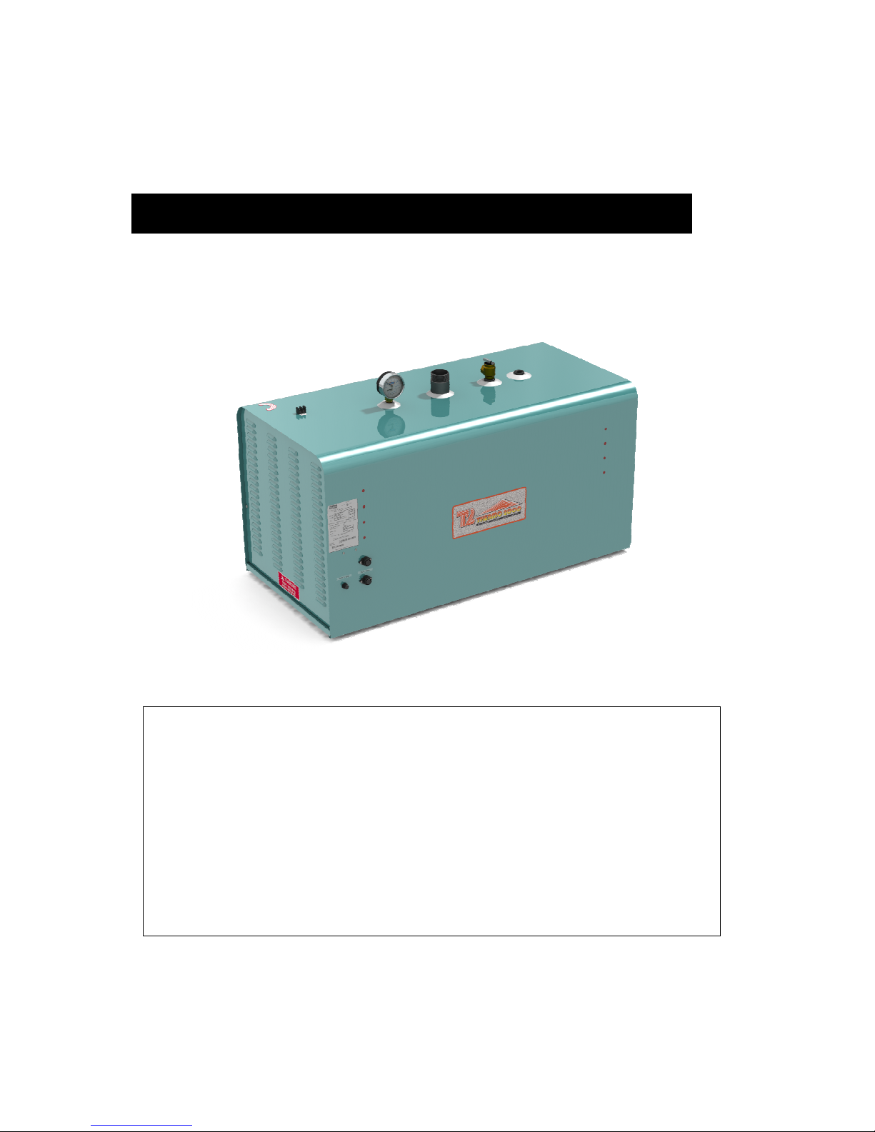
DTH
Electric Boilers
M
odels ranging from 42 kW to 144 kW :
240 Volts ( 1 phase ) , 480 and 600 Volts ( 3 phases ).
USE & CARE MANUAL
WITH INSTALLATION INSTRUCTIONS FOR THE CONTRACTOR
Your DTH’s Electric Boiler has been carefully assembled and factory tested to provide years
of trouble-free service. In order to ensure performance, the following information and safety
precautions are provided to enable proper installation, operation, and maintenance of this
product.
It is imperative that all persons who are expected to install, operate or adjust this electric
boiler should read these instructions carefully to fully understand how to do so.
Any questions regarding the operation, maintenance, service or warranty of this electric
boiler should be directed to the supplier.
When all installation steps have been completed, insert this installation manual in its original
envelope, and keep in a safe place (close to the boiler) for future reference.
THERMO 2000 INC. Revision June 2014
Printed in Canada

DTH Electric Boilers USE & CARE MANUAL
(Revision June 2014)
, Page 2.
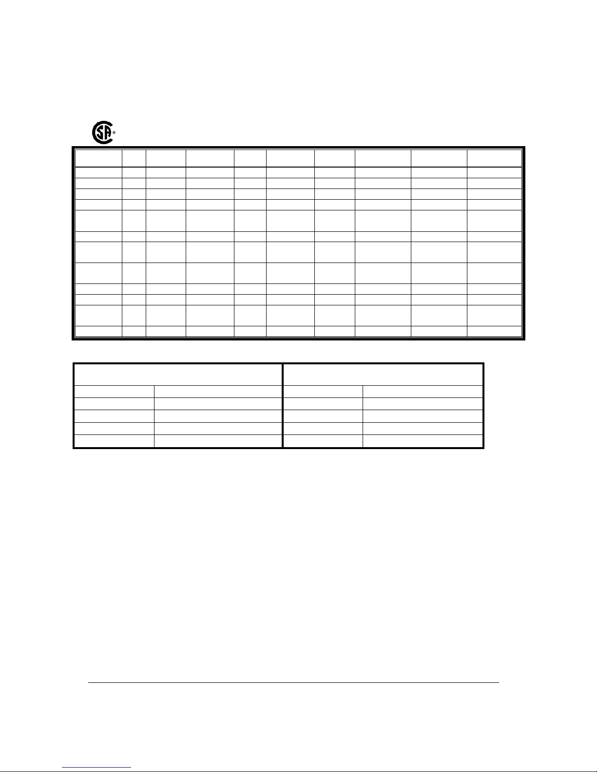
Section 1 : Dimensions & Specifications
Table 1: Electric Ratings for 240 VAC (1 phase) Electric Boilers:
Model
P
Kw
Current
Amp
Heating
Elements
Elements
Stages
Aquastats
Lights
Contactors
Sequencers
DTH 42 42 175 7 X 6KW 7 7 7 2 1
DTH 48 48 200 8 X 6KW 8 8 8 2 1
DTH 54 54 225 9 X 6KW 9 9 9 3 2
DTH 60 60 250 10 X 6KW 10 10 10 3 2
DTH 66 66 275 11 X 6KW 11 11 11 3 2
DTH 72 72 300 12 X 6KW 12 12 12 3 2
DTH 78 78 325 13 X 6KW 13 13 13 4 3
DTH 84 84 350 14 X 6KW 14 14 14 4 3
DTH 90 90 375 15 X 6KW 15 15 15 4 3
DTH 96 96 400 16 X 6KW 16 16 16 4 3
Table 2: Electric Ratings for 480 VAC (3 phases) Electric Boilers:
Model
P
Kw
Current
Amp
Élements
(277V)
Stages Aquastats Lights
Power
contactors
Secondary
contactors
Sequencers
DTH 45 45 54 9 X 5KW 3 3 3 2 3 1
DTH 54 54 65 9 X 6KW 3 3 3 2 3 1
DTH 60 60 72 12 X 5KW 4 4 4 2 4 1
DTH 72 72 87 12 X 6KW 4 4 4 2 4 1
DTH 78 78 94
12 X 5KW
3 X 6KW
5 5 5 3 5 2
DTH 90 90 108 15 X 6KW 5 5 5 3 5 2
DTH 99 99 119
9 X 5KW
9 X 6KW
6 6 6 3 6 2
DTH 102 102 123
12 x 6KW
6 x 5Kw
6 6 6 3 6 2
DTH 108 108 130 18 x 6 KW
6 6 6 3 6 2
DTH 120 120 144 24 X 5KW 8 8 8 4 8 3
DTH 132 132 159
12 X 5KW
12 X 6KW
8 8 8 4 8 3
DTH 144 144 173 24 X 6KW 8 8 8 4 8 3
DTH Electric Boilers USE & CARE MANUAL
(Revision June 2014)
, Page 3.
Table 3: Electric Ratings for 600 VAC (3 phases) Electric Boilers:
Model
P
Kw
Current
Amp
Élements
(347V)
Stages Aquastats Lights
Power
contactors
Secondary
contactors
Sequencers
DTH 45 45 43 9 X 5KW 3 3 3 2 3 1
DTH 54 54 52 9 X 6KW 3 3 3 2 3 1
DTH 60 60 58 12 X 5KW 4 4 4 2 4 1
DTH 72 72 69 12 X 6KW 4 4 4 2 4 1
DTH 78 78 75
12 X 5KW
3 X 6KW
5 5 5 3 5 2
DTH 90 90 87 15 X 6KW 5 5 5 3 5 2
DTH 99 99 95
9 X 5KW
9 X 6KW
6 6 6 3 6 2
DTH 102 102
98
12 x 6KW
6 x 5Kw
6 6 6 3 6 2
DTH 108 108 104 18 x 6 KW 6 6 6 3 6 2
DTH 120 120 115 24 X 5KW 8 8 8 4 8 3
DTH 132 132 127
12 X 5KW
12 X 6KW
8 8 8 4 8 3
DTH 144 144 139 24 X 6KW 8 8 8 4 8 3
Table 4: Connections sizes & Boiler overall dimensions
Connections sizes Boiler overall dimensions
Boiler inlet 2 “ NPT M Height 33 po
Boiler outlet 2 “ NPT M Depth 46 po
Waterworks 1/2 “ NPT M Width 22 po
Safety valve 3/4 “ NPT F Shipping weight 395lbs
Drain valve 3/4 “ NPT M Volume 35.6 Gal US.
Operating temperature : from 50°F to 190°F.;
Maximum operating pressure:
Models at 480 & 600V :
45 to 72 kW : 30 psi. or 60psi
(See boiler identification plate)
78 to144kW :: 60psi
Models at 240V/1ph :
42 & 48kW : 30 psi ou 60lpsi
(See boiler identification plate)
54 to 96kW : 60 psi
DTH Electric Boilers USE & CARE MANUAL
(Revision June 2014)
, Page 4.
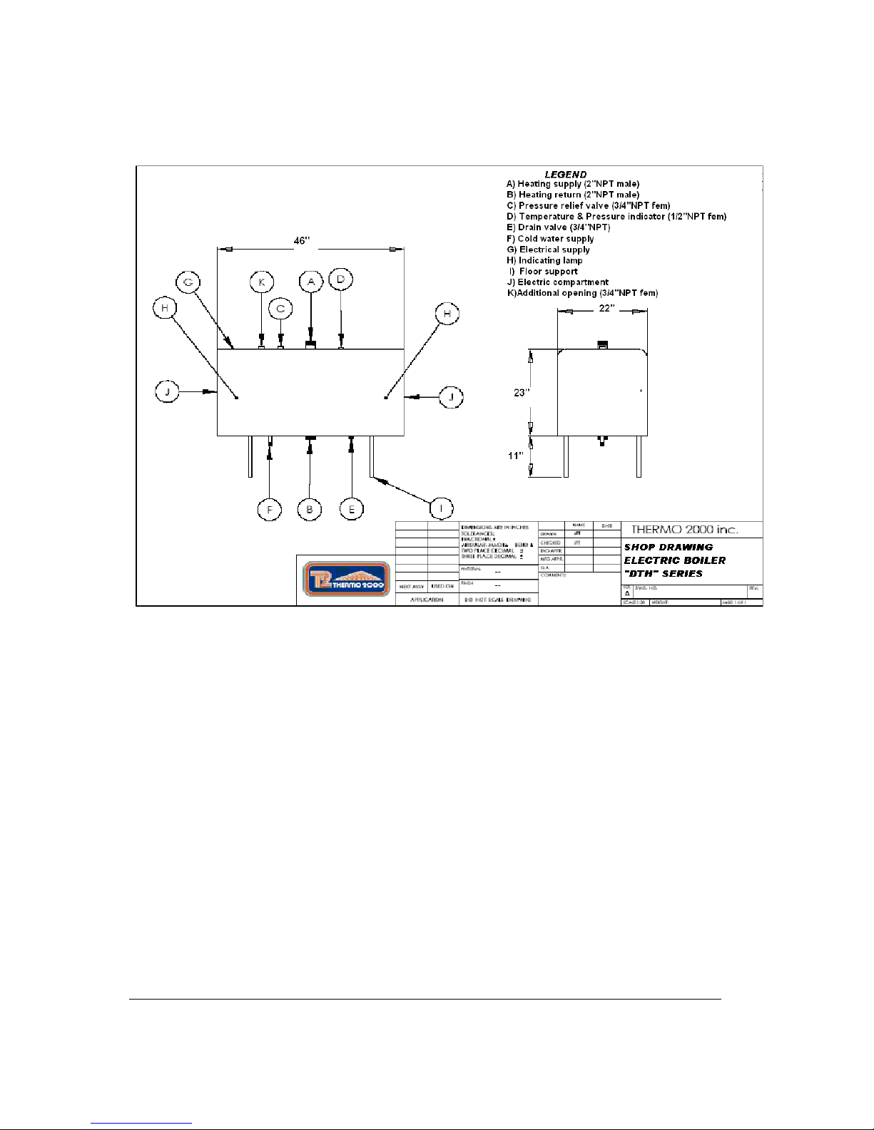
Figure 1 : Component identification

DTH Electric Boilers USE & CARE MANUAL
(Revision June 2014)
, Page 5.
General Safety Precautions
Be sure to read and understand the entire Use & Care Manual before attempting to install or to
operate this electric boiler. Pay particular attention to the following General Safety Precautions.
Failure to follow these warnings could cause property damage, bodily injury or death. Should
you have any problems understanding the instructions in this manual, STOP, and get help from
a qualified installer or technician.
Section 2 : Introduction
The important safeguards and instructions
appearing in this manual are not meant to
cover all possible conditions and situations
that may occur. It should be understood that
common sense, caution and care are factors
which cannot be built into every product.
They are the responsibility of the person(s)
caring for and operating the unit.
2.1 LOCAL INSTALLATION
REGULATIONS
This electric boiler must be installed in
accordance with these instructions and in
conformity with local codes, or in the absence of
local codes, with the National Plumbing Code
and the National Electric Code current edition.
In any case where instructions in this manual
differ from local or national codes, the local or
national codes take precedence.
2.2 CORROSIVE ATMOSPHERE
The electric boiler should not be located near an
air vent containing a corrosive atmosphere or
high humidity. The limited warranty is void when
the failure of the electric boiler is due to a
corrosive atmosphere.
2.3 SHIPMENT INSPECTION
Inspect the electric boiler for possible shipping
damage. The manufacturer’s responsibility
ceases upon delivery of goods to the carrier in
good condition. Consignee must file any claims
for damage, shortage in shipments, or nondelivery immediately against carrier.
2.4 CHECK LIST
Please check the identification tag on the unit to
make sure you have the right model, voltage and
pressure rating.
List of components shipped with the unit :
• Pressure relief valve.
• Drain valve.
• Tridicator (temperature & pressure
gage).
The electric boiler should not be located in
an area where leakage of the tank or water
connections will result in damage to the
adjacent area or to lower floors of the
structure. When such areas cannot be
avoided, a suitable drain pan or nonflammable catch pan, adequately drained,
must be installed under the boiler.
The pan must be connected to a drain.
NOTE: Auxiliary catch pan MUST conform to
local codes.
!
CAUTION
!
WARNING
!
DTH Electric Boilers USE & CARE MANUAL
(Revision June 2014)
, Page 6.
Section 3 : INSTALLATION
The manufacturer’s warranty does not cover
any damage or defect caused by installation,
or attachment, or use of any special
attachment other than those authorized by
the manufacturer, into, onto, or in
conjunction with the boiler. The use of such
unauthorized devices may shorten the life of
the boiler and may endanger life and
property. The manufacturer disclaims any
responsibility for such loss or injury
resulting from the use of such unauthorized
devices
3.1 SECURITY CONSIDERATIONS
Domestic and commercial installations have a
maximum design operating pressure limited to
30 psi (207 kPa) or 60psi (414kPa) by a safety
relief valve.
Boiler maximum operating temperature is 190°F
by design. This boiler is designed to be used
only in a hot water heating system.
The heat transfer medium must be water or
other non-toxic fluid. An antifreeze solution
with propylene glycol specially formulated
for heating system could be used up to a
maximum concentration of 50%
3.2 LOCATION
The electric boiler should be installed in a clean,
dry location. Long hot water lines should be
insulated to conserve energy. The electric boiler
and water lines should be protected from
exposure to freezing temperatures.
The electric boiler must be installed horizontally
directly on the floor or wall. Supporting legs are
included but wall mounting brackets are not.
The electric boiler must be located or protected
so as not to be subject to physical damage, for
example, by moving vehicles, area flooding, etc.
All models can be installed on combustible floors
and in alcoves. Ambient temperature must not
exceed 80°F or 27°C.
3.3 CLEARANCE
Minimum clearances for adequate inspection
and servicing are listed in the following table:
Table 4: Boiler clearance
Left side 14 inches
Right side 14 in.(78to144kW 480&600v)
(54to96kWx 240v)
0in. Other models
Top & bottom of
the boiler
12 inches
Front side of the
boiler
24 inches
Back side of the
boiler
0 inch
3.4 SYSTEM SETUP
The recommended piping arrangement is shown
in Figure 4, 5 and 6 including the pump,
expansion tank, drain valve, pressure relief
valve, air vent, flow check valve and pressuretemperature gauge. Details about each item
follow.
3.4.1 Boiler connections
This electric boiler may be connected
individually or in parallel with other boilers. If two
or more boilers are connected, the “reversereturn piping” method (whereby the boiler with
the first return inlet also has the last supply
outlet and so forth until the last return inlet
corresponds to the first supply outlet) should be
used to connect the boilers in parallel, to ensure
an equal water flow rate through each boiler.
The boiler water supply, located on the top side,
and the boiler water return, located on the
bottom side of the boiler are steel pipes (male
NPT threaded connection) where supply and
return line connections are to be made.
Installing a union is recommended on the boiler
water supply and return lines to facilitate boiler
disconnection for servicing.
Dielectric unions are required for protection of
the boiler and piping if dissimilar pipe material
such as galvanized steel and copper are
present.
WARNING
!
CAUTION
!

DTH Electric Boilers USE & CARE MANUAL
(Revision June 2014)
, Page 7.
Use only clean, new piping for boiler water lines.
Local codes or regulations shall govern the
exact type of material to be used.
Insulate all pipes containing hot water,
especially in unheated areas.
Install shutoff (ball) valves for servicing
convenience. Thermometer(s) should be
installed on the boiler water supply and return
lines.
Cap or plug unused connections on the boiler.
Do not cap the pressure relief valve on the
boiler since it will damage and shorten the life of
the boiler and may endanger life and property.
3.4.2 Flow check valve
If the heating system includes a single pump,
then to minimize flow by gravity and heat loss
during non-draw periods, a flow check valve
must be installed.
3.4.3 Pressure relief valve
An automatic pressure relief valve must be
installed during boiler setup. The pressure
rating of the relief valve must not exceed the
pressure design of the boiler as shown on the
pressure vessel name plate. The safety relief
valve must meet the requirements of the ASME
Boiler and Pressure Vessel Code and limit the
maximum operating boiler pressure. It is a
safety device, not an operating control.
The BTU per hour rating of the relief valve must
equal or exceed the BTU per hour input of the
boiler(s) or heat source(s) as marked on the
boiler(s) rating plate.
Connect the outlet of the relief valve to a
discharge line with its lower tip at most 6” above
a floor drain, well clear of any live electrical
parts. The discharge line must pitch downward
from the valve to allow complete draining by
gravity of the relief valve and discharge line, and
be of a diameter no smaller than that of the
valve outlet. The tip of the discharge line should
not be threaded or concealed and should be
protected from freezing. No valve of any type,
restriction or reducer coupling should be
installed on the discharge line. Local codes
shall govern the installation of relief valves.
3.4.4 System pressure control and
expansion tank
Pressure control devices within the system
ensure that each component operates within
minimum and maximum allowable pressures
and maintain minimum pressure for all normal
operating temperatures. They also allow air
bleeding, prevent cavitation at the pump inlet
and prevent water from boiling within the
system; all this is accomplished with minimal
addition of new water.
The increase in boiler water volume resulting
from higher temperature is stored in the
expansion tank during periods of high operating
temperature and is returned to the system when
the temperature decreases.
The expansion tank must be able to store the
required volume of boiler water during maximum
design operating temperature without exceeding
the maximum allowable operating pressure, and
to maintain the required minimum pressure
when the system is cold. Contact your installing
contractor, plumbing supply house, or local
plumbing inspector for assistance.
The point where the expansion tank is
connected should be carefully selected to avoid
the possibility that normal operation of automatic
check or manual valves will isolate the tank from
a hot boiler or any part of the system. Precharged diaphragm expansion tanks are
preferable to air control (see section 3.4.6).
These tanks incorporate a balloon-like bladder
or diaphragm. It is inflated, prior to filling the
system, to a pressure equal to the setting of the
water pressure makeup regulator.
The expansion tank should be located on the
suction or intake side of the pump. The pump
can be located either just upstream or just
downstream from the boiler.
3.4.5 Water pressure makeup regulator
Make-up systems must be employed as
required by codes. An automatic fill valve
must be used with a backflow preventer as
required, to maintain minimum system pressure
by supplying water to make up for leakage.
3.4.6 Air bleeder
Oxygen should be excluded from the system to
prevent corrosion. As hinted at in section 3.4.4,
this precludes the use of air in direct contact with
the boiler water as a pressurization means.
Installation of manual or automatic air vent
devices prevents air from accumulating in the
system. Air vents should be installed at all high
points to remove trapped air during initial setup
and to ensure that the system is tight. Regularly
purge the air out of the system while taking care
to avoid personal injuries or property damage
caused by hot boiler water spray.

DTH Electric Boilers USE & CARE MANUAL
(Revision June 2014)
, Page 8.
3.4.7 Circulator zoning recommendations
The preferred location of the circulator pump for
each zone is on the boiler supply side, with the
expansion tank between the boiler and the
pump.
A flow check valve must be installed in each
zone, preferably on the outlet side of each
circulator pump, to prevent water flow to other
zones where no heat is required.
3.4.8 Zone valve zoning
recommendations
The preferred location of the circulator pump is
on the boiler supply side, with the expansion
tank between the boiler and the circulator. Use
zone valves with low pressure drop.
3.4.9 Pump & pipe sizing
3.4.9.1 Boiler water temperature drop (BWTD)
through the heating loop
A simplified design method based on a 20°F
temperature drop (BWTD) between boiler outlet
and inlet is commonly used. Although such a
method is widely used and generates
satisfactory system performance when applied
properly, it does not determine the system
operating point. The pipe size is often
uneconomically large, and the actual system
flow rate is likely to be much higher than
intended. Such design methods seldom
consider temperature drops higher than 20°F,
which results in overdesign.
Another method by which the boiler water
temperature drop (BWTD) could be calculated
is to assume a constant supply boiler water
temperature minus the return boiler water
temperature. For example a boiler might have
a return temperature of 140 °F. Assuming a
constant supply boiler temperature of 180 °F,
the BWTD would be 40 °F ( = 180 °F – 140 °F).
Second example: If the boiler water has a return
temperature of 120 °F and the boiler supply is at
140 °F, then the temperature drop is 20 °F
(=140 °F – 120 °F).
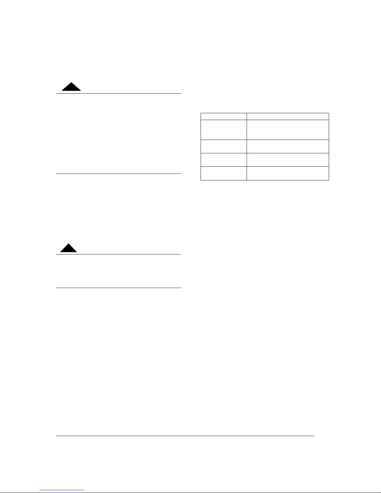
The following table suggests temperature drops
(BWTD) to be used in calculating the pump flow
rate.
Table 5: Temperature rise through the boiler
PROPOSED BOILER WATER
TEMPERATURE RISE THROUGH THE
BOILER (BWTD)
System
type
Boiler
water
Supply
tempera-
ture
Boiler
water
Return
tempera-
ture
BWTD
Baseboards
190°F to
140°F
170°F to
120°F
20°F to
40°F
Cast Iron
Radiators
160°F to
130°F
140°F to
110°F
20°F to
40°F
Radiant
In-Floor
130°F to
90°F
110°F to
70°F
10°F to
20°F
3.4.9.2 Pump flow rate calculation
The boiler output rating must correspond to the
calculated heating load. Use the equation below
to calculate the pump flow rate.
Pump flow rate = Boiler output ÷÷÷÷
BWTD ÷÷÷÷ 500
• Pump flow rate is expressed in US gallons
per minute or GPM.
• The Boiler output ( in net BTU per hour) is
the maximum amount of heat to be
transferred through the heating loop to meet
the heating load.
• BWTD is the boiler water temperature drop
For example, an electric boiler rated at 144KW
has a power output of 491,328 BTU per hour.
The system is designed for a temperature drop
(BWTD) of 20°F.
Required pump flow rate = 491,328 ÷ 20 ÷ 500 =
49.1 GPM
The following table lists the required pump flow
rate as a function of boiler power and BWTD.
 Loading...