

THERMO 2000 COMBOMAX 23-8, Combomax 23, COMBOMAX 23-24, COMBOMAX 34-8, COMBOMAX 34-10 Use And Care Manual
...
MC
COMBOMAX
RÉSIDENTIAL
23
TO
64
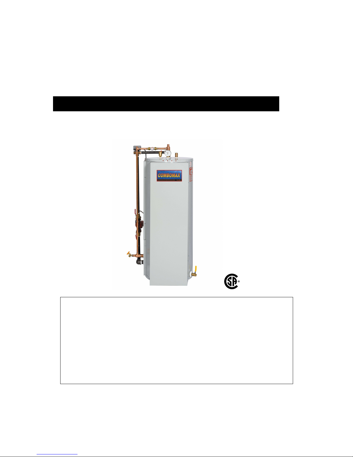
Electric boiler with integrated instantaneous water heater
Capacity from 8 kW to 24 kW :
240 Volts ( single phase )
Use and Care Manual
With installation instructions for the contractor
Your COMBOMAX® electric boiler has been carefully assembled and factory tested to
provide years of trouble-free service. This manual contains instructions for the safe and
proper installation, operation and maintenance of the boiler, in order to ensure your full
satisfaction
It is imperative that all persons who are expected to install, operate or adjust this boiler read
the instructions carefully.
Any questions regarding the operation, maintenance, service or warranty of this water
heater should be directed to the dealer or distributor you purchased it from. When all
installation steps have been completed, replace this installation manual in its original
envelope, and keep in a safe place near the heater for future reference.
THERMO 2000 INC. revised : Oct. 2015
Printed in Canada
COMBOMAXMC Electric boiler Set-up, use and care guide
(revised Oct 2015)
, Page 2.
Section 1 : Technical specifications
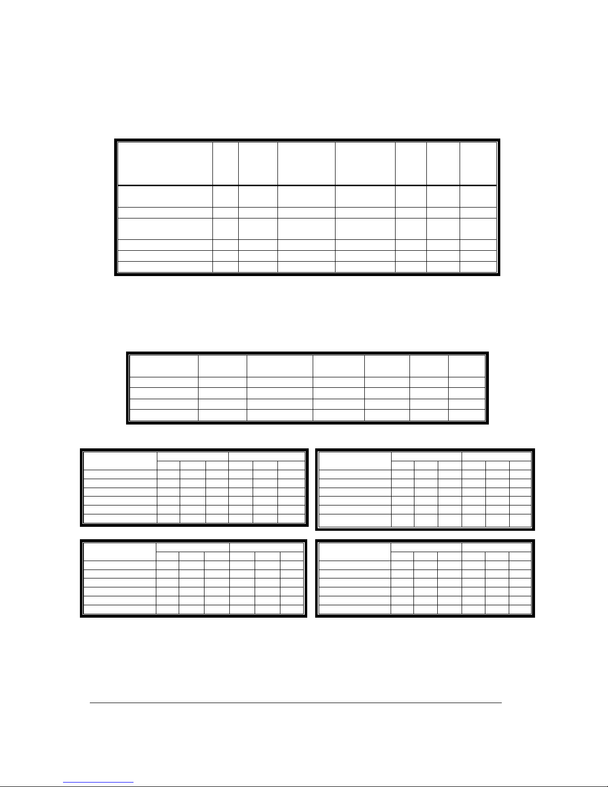
Table 1: Boiler specifications 240* Vac/1ph (3 wires L1/L2/N):
Modèle
Kw
À
240
V*
BTU/h
Amp.
Heating
elements
Heating
elements
Stage
Cable
(cu)**
Fuse **
COMBOMAX XX-8 8 27 296 33.3
1 X 3KW
1 X 5KW
2 8 50
COMBOMAX XX-10 10 34 120 41.6 2 X 5KW 2 6 60
COMBOMAX XX-15 15 51 180 62.5
2 X 3KW
2 X 4.5KW
4 6 80
COMBOMAX XX-18 18 61 416 75.0 4 X 4.5KW 4 4 100
COMBOMAX XX-20 20 68 240 83.4 4 X 5KW 4 3 110
COMBOMAX XX-24 24 81 888 100.0 4 X 6KW 4 3 125
*Can be also connected on an electrical supply at 208V/1ph giving 75% of the nominal capacity at 240V.
**Add amperage of the pump when required (8amp./1/3hp max). Local Electrical codes may require
different cable gauge according to the type of installation.
Table 2 : Boiler and connection dimensions
Model Capacity Utility
connection
Boiler
connection
Height Diam. Ship.
weight
Combomax 23 30 Gal US 3/4 ’’ Sweat F 1’’ NPT F 49’’ 18’’ 265 lbs
Combomax 34 40 Gal US 3/4 ’’ Sweat F 1’’ NPT F 65’’ 18’’ 315 lbs
Combomax 44 52 Gal US 3/4 ’’ Sweat F 1’’ NPT F 55’’ 22’’ 345 lbs
Combomax 64 76 Gal US 3/4 ’’ Sweat F 1’’ NPT F 67’’ 24’’ 425 lbs
Table 3 : Domestic hot water production capacity in US gallons
1st hour Continuous Model
110F 140F 180F 110F 140F 180F
COMBOMAX 23-8 75 44 28 47 33 24
COMBOMAX 23-10 87 52 33 59 41 29
COMBOMAX 23-15 116 73 48 88 62 44
COMBOMAX 23-18 134 85 57 106 74 53
COMBOMAX 23-20 145 93 63 117 82 59
COMBOMAX 23-24 169 110 75 141 99 71
1st hour Continuous Model
110F 140F 180F 110F 140F 180F
COMBOMAX 34-8 85 48 29 47 33 24
COMBOMAX 34-10 97 56 34 59 41 29
COMBOMAX 34-15 126 77 49 88 62 44
COMBOMAX 34-18 144 89 58 106 74 53
COMBOMAX 34-20 155 97 64 117 82 59
COMBOMAX 34-24 179 114 76 141 99 71
1st hour Continuous Model
110F 140F 180F 110F 140F 180F
COMBOMAX 44-8 97 53 31 47 33 24
COMBOMAX 44-10 109 61 36 59 41 29
COMBOMAX 44-15 138 82 51 88 62 44
COMBOMAX 44-18 156 94 60 106 74 53
COMBOMAX 44-20 167 102 66 117 82 59
COMBOMAX 44-24 191 119 78 141 99 71
1st hour Continuous Model
110F 140F 180F 110F 140F 180F
COMBOMAX 64-8 121 63 34 47 33 24
COMBOMAX 64-10 133 71 39 59 41 29
COMBOMAX 64-15 162 92 54 88 62 44
COMBOMAX 64-18 180 104 63 106 74 53
COMBOMAX 64-20 191 112 69 117 82 59
COMBOMAX 64-24 215 129 81 141 99 71
With domestic cold water at 40
°F and heating water at 180°F
Operating temperature : from 50°F to 190°F; Maximum operating pressure: 30 psi

COMBOMAXMC Electric boiler Set-up, use and care guide
(revised Oct 2015)
, Page 3.
Figure 1 : Component diagram

COMBOMAXMC Electric boiler Set-up, use and care guide
(revised Oct 2015)
, Page 4.
General Safety Precautions
Be sure to read and understand the entire Use & Care Manual before attempting to
install or operate this water heater. Pay particular attention to the following General
Safety Precautions. Failure to follow these warnings could cause property damage,
bodily injury or death. Should you have any problems understanding the instructions in
this manual, STOP, and get help from a qualified installer or technician.
Section 2 : Introduction
The important safeguards and instructions
appearing in this manual are not meant to
cover all possible conditions and situations
that may occur. It should be understood that
common sense, caution and care are factors
which cannot be built into every product.
These factors must be supplied by the
person(s) caring for and operating the unit.
2.1 LOCAL INSTALLATION
REGULATIONS
This water heater must be installed in
accordance with these instructions and must
conform to local, or in the absence of local
codes, with the current edition of the National
Plumbing Code and the National Electric Code.
In any case where instructions in this manual
differ from local or national codes, the local or
national codes take precedence.
2.2 CORROSIVE ATMOSPHERE
The heater should not be located near an air
supply containing halogenated hydrocarbons or
high humidity. The limited warranty is voided
when failure of the water heater is due to a
corrosive atmosphere.
2.3 SHIPMENT INSPECTION
Inspect the water heater for possible shipping
damage. The manufacturer’s responsibility
ceases upon delivery of goods to the carrier in
good condition. Consignee must file any claims
for damage, shortage in shipments, or nondelivery immediately against carrier.
2.4 CHECKLIST
Please check the technical information plate to
ensure you have the right model.
The following items are shipped with the
unit :
• 30 PSI pressure relief valve.
• Drain cock.
• Thermo manometer (heat and
pressure indicator).
• Thermostatic mixing valve
The boiler should not be located in an area
where leakage from the tank or water
connections will result in damage to the
adjacent area or to lower floors of the
structure. When such areas cannot be
avoided, a suitable drain pan or nonflammable catch pan, adequately drained,
must be installed under the boiler. The pan
must be connected to a drain.
NOTE: Auxiliary catch pan MUST conform to
local codes.
!
WARNING
!
WARNING
!

COMBOMAXMC Electric boiler Set-up, use and care guide
(revised Oct 2015)
, Page 5.
Section 3 : INSTALLATION
The manufacturer’s warranty does not cover
any damage or defect caused by installation
or attachment or use of any special
attachment other than those authorized by
the manufacturer into, onto, or in
conjunction with the water heater. The use of
such unauthorized devices may shorten the
life of the water heater and may endanger life
and property. The manufacturer disclaims
any responsibility for such loss or injury
resulting from the use of such unauthorized
devices.
3.1 SAFETY MEASURES
All domestic and commercial installations will
include a pressure relief valve limiting the
operating pressure to 30 psi.
This COMBOMAXMC electric boiler is designed
for a maximum operating temperature of 190°F.
It is designed as a hot water heating system
only. When allowed by local regulation an
antifreeze water and propylene-glycol blend
(50% maximum concentration) may be used on
installations having a potable water supply
pressure above 240 kPa (35 psi).
3.2 LOCATION
The COMBOMAXMC water heater should be
installed in a clean, dry location. Long hot water
lines should be insulated to conserve water and
energy. The water heater and water lines should
be protected from exposure to freezing.
COMBOMAX
MC
water heaters must be installed
vertically. Use the adjustable feet to level the
unit.
The COMBOMAXMC water heater must be
located or protected so as not to be subject to
physical damage, for example, by moving
vehicles, area flooding, etc..
All models can be installed on combustible floors
and in alcoves. If the water heater is to be
installed in a restaurant or other location where
the floor is frequently cleaned, it must be
elevated to provide at least 6 inches of
clearance from the floor to comply with NSF
International recommendations.
The room temperature must not exceed 80°F or
27°C.
3.3 CLEARANCE
The minimum clearances required for proper
inspection and servicing are as follows:
Table 4: Clearances
Left side 3 inches
Right side 3 inches
Top 6 inches
Front 24 inches
Back 3 inches
3.4 SYSTEM SETUP
Figures 2, 3 and 4 are general connection
diagrams including the circulator, the expansion
tank, the drain cock, the safety valve, the air
bleeder, the flow check valve and the thermo
manometer. Set-up details follow.
3.5 HEATING WATER CIRCUIT
3.5.1 Connecting the heating water
piping
The boiler may be set up alone or in parallel with
others. Parallel connections should be made
using the reverse-piping method to ensure equal
flow through each boiler.
The boiler water supply connector is located on
top of the boiler and the boiler water return
connector is located to the left of the three-way
valve. They are both threaded NPT female
connectors.
Unions are recommended on the hot and cold
water lines to disconnect the water heater easily
for servicing if necessary.
Dielectric (insulating) unions are required for
protection of the water heater if copper-steel
connections are made.
Use only clean copper or approved plastic pipe
for water connections. Local codes or
regulations shall govern the exact type of
material to be used.
WARNING
!

COMBOMAXMC Electric boiler Set-up, use and care guide
(revised Oct 2015)
, Page 6.
Insulate all pipes containing hot water,
especially in unheated areas.
Install shutoff (ball) valves for servicing
convenience. Install thermometers on the inlet
and outlet lines.
Never plug the pressure relief valve to avoid
creating a hazardous situation.
3.5.2 Flow-check valve
If the heating system uses a single circulator, a
flow-check valve must be installed to
minimize gravity flow and heat loss during nondraw periods.
3.5.3 Pressure relief valve
No boiler set-up is complete without a pressure
relief valve. Its pressure rating must not exceed
30 psi (207 kPa). It must conform to the « ASME
Boiler and Pressure Vessel Code» and limit the
boiler operating pressure. It is a safety device,
not a control device.
The BTU per hour rating of the relief valve must
equal or exceed the BTU per hour input of the
boiler(s) or heat source(s) as marked on the
boiler(s) rating plate.
Connect the outlet of the relief valve to a
suitable open drain, with the discharge at most
6” above the floor, far from any live electrical
parts. The discharge line must pitch downward
from the valve to allow complete draining and be
no smaller than the outlet of the valve. The end
of the discharge line should not be threaded or
concealed and should be protected from
freezing. No valve of any type, restriction or
reducer coupling should be installed in the
discharge line. Local codes shall govern the
installation of relief valves.
3.5.4 Operating pressure control :
Operating pressure control components ensure
minimum and maximum operating limits within
the design operating temperature range of the
heating system.
Expansion tank
The purpose of the expansion tank is to absorb
the water volume increase of the boiler and the
heating system related to the variation of its
water temperature during the heating season.
Consequently, the selection of the appropriate
expansion tank model must be made taking into
account both the maximum operating
temperature of the system and its water content.
Note that the water content of an heating system
with cast iron radiators is a lot more than a
system with hot water baseboard.
The important increase of heating water volume
brought with the addition of the Combomax will
also have to take into account.
Combomax 23 : 30usgal.
Combomax 34 : 40usgal
Combomax 44 : 52usgal
Combomax 64 : 76usgal
With these informations, these informations, the
installer with his distributor shall be in position to
make an appropriate selection.
You will find below our recommendation on the
minimum size of tank in relation to the type of
heating system of the application.
Combomax #
Hot water
Baseboards
Radiant
floor
Cast iron
radiator
Combomax 23
#30 #30 #60
Combomax 34
#30 #30 #60
Combomax 44
#30 #30 #60
Combomax 64
#60 #60 #90
The expansion tank connection point must be
carefully chosen to prevent a situation where
closing a valve would isolate the tank from the
boiler or any part of the circuit.
3.5.5 Makeup valve
Connecting a makeup valve must be done
according to code. This valve must include a
flow-check valve to maintain the minimum
operating pressure by admitting fresh water from
the cold water supply line in case a leak occurs.
3.5.6 Air bleeder
There should be as little oxygen as possible in
the heating circuit to prevent corrosion. As
foreseen in section 3.5.4, this excludes the use
of air as a pressure regulator within the circuit.
Installing manual or automatic air bleeders
prevents air accumulation within the system.
The bleeders must be set at the highest points
of the system to purge any air accumulated
during system set-up and to check its air
tightness. Bleed the air regularly from the piping,
making sure the heating water causes no bodily
harm or material damage.
COMBOMAXMC Electric boiler Set-up, use and care guide
(revised Oct 2015)
, Page 7.
3.5.7 Circulator zoning
A flow-check valve must be installed in each
zone, preferably at the outlet of each circulator,
to prevent water flowing to zones where no heat
is currently required. (see figure 4).
3.5.8 Zone valve zoning
Zone valves with low pressure drop are
recommended. (see figure 3)
3.5.9 Circulator selection criteria
The COMBOMAXMC boiler includes a premounted circulator. The information below will
help you select additional units for multiple
circulator set-ups.
3.5.9.1 Pump flow rate calculation
The boiler output rating must correspond to the
calculated heating load. Use the equation below
to calculate the pump flow rate:
Pump flow rate = Boiler output ÷÷÷÷ BWTD ÷÷÷÷ 500
• Pump flow rate is expressed in U.S. gallons
per minute or GPM.
• The Boiler output ( in net BTU per hour) is
the maximum amount of heat to be
transferred through the heating circuit to
meet the hot water demand.
• BWTD is the boiler water temperature drop
through the heating circuit.
For example, a 24 Kw COMBOMAXMC boiler has
a rated output of 81,964 BTU/hour. The system
is designed for a boiler water temperature drop
(BWTD) of 20°F.
Pump flow rate = 81,964 ÷ 20 ÷ 500 = 8,2 GPM.
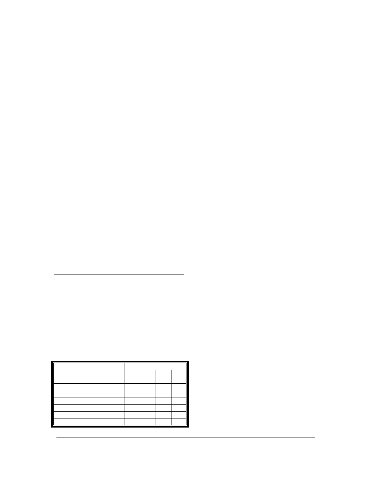
The following table shows the required flow rate
as a function of boiler water temperature drop
(BWTD) and rated power output.
Table 5 : BWTD vs. flow (GPM)
BWTD
Model Kw
10
o
F
20
o
F
30
o
F
40
o
F
COMBOMAX XX-8 8 5,5 2,7 1,8 1,4
COMBOMAX XX-10 10 6,8 3,4 2,3 1,7
COMBOMAX XX-15 15 10,2 5,1 3,4 2,6
COMBOMAX XX-18 18 12,3 6,1 4,1 3,1
COMBOMAX XX-20 20 13,7 6,8 4,6 3,4
COMBOMAX XX-24 24 16,4 8,2 5,5 4,1
3.5.9.2 Selecting a circulator
Consult the manufacturer’s operating
characteristic curves to select the proper model.
These curves plot flow versus pressure, together
with other information such as efficiency and
power. Ask your pump dealer or HVAC
wholesaler to recommend the circulator which
best fits your needs.
3.6 DOMESTIC HOT WATER CIRCUIT
3.6.1 Connecting the domestic hot water
piping
The COMBOMAX
MC
domestic hot water coil may
be set up alone or in parallel combination with
other COMBOMAXMC units or storage tanks.
Parallel connections should be made using the
reverse-piping method to ensure equal flow
through each boiler.
The HOT WATER OUTLET and the COLD
WATER INLET connections are clearly marked.
Inlet water connections (COLD WATER INLET)
are to be made to the copper pipe (sweat
connection) at the bottom of the heater. Outlet
water connections (HOT WATER OUTLET) are
to be made to the three-way thermostatically
controlled valve (sweat connection) at the top of
the heater.
The installation of copper unions or copper alloy
unions is recommended on the HOT and COLD
water lines, so that the water heater may be
easily disconnected for servicing if necessary.
These unions must be dielectric (insulating) if
you are making steel-copper connections.
A shutoff (ball) valve is present on the
COMBOMAXMC domestic hot water outlet for
servicing convenience.
Use only clean copper or approved plastic pipe
for water connections. Local codes or
regulations shall govern the exact type of
material to be used.
Insulate all pipes containing hot water,
especially in unheated areas.
Thermometer(s) should be installed to indicate
the temperature of the water at or near the outlet
of the water heater and storage tank(s), if
provided.

COMBOMAXMC Electric boiler Set-up, use and care guide
(revised Oct 2015)
, Page 8.
3.6.2 Expansion tank on the cold water
supply line
Determine if a flow check valve, a back flow
preventer, a pressure-reducing valve, a water
meter or a water softener is present on the cold
water supply line.
A flow check valve creates a closed system and
prevents the water, as it is being heated, from
expanding back into the cold water supply line.
Pressure can build up within the water heater,
causing the pressure relief valve to operate
during a heating cycle. This excessive operation
can cause premature failure of the relief valve
and possibly of the water heater itself.
Replacing the relief valve will not correct the
problem. One method of preventing pressure
build-up is to install an expansion tank on the
cold water supply line between the
COMBOMAXMC unit and flow check valve.
Contact your installing contractor, water
supplier, local plumbing inspector or plumbing
supply house for assistance.
3.6.3 Recirculation line (if applicable)
If a recirculation line is installed, the return
connection should be made to a tee close to the
inlet connection on the water heater. A check
valve should always be installed in the
recirculation line to prevent cold water from
entering.
3.6.4 Domestic hot water pressure relief
valve
An automatic pressure relief valve must be
installed on a tee installed on the domestic hot
water pipe coming out of the water heater. No
valve of any type should be placed between the
safety relief valve and the water heater. The
pressure rating of the relief valve must not
exceed 150 psi.
The BTU per hour rating of the relief valve must
equal or exceed the BTU per hour input of the
boiler(s) or heat source(s) as recorded on the
boiler(s) rating plate.
Connect the outlet of the relief valve to a
suitable open drain, with the discharge at most
6” above the floor, far from any live electrical
parts. The discharge line must pitch downward
from the valve to allow complete draining and be
no smaller than the outlet of the valve. The end
of the discharge line should not be threaded or
concealed and should be protected from
freezing. No valve of any type, restriction or
reducer coupling should be installed in the
discharge line. Local codes shall govern the
installation of relief valves.
3.6.5 Thermostatically controlled mixing
valve (included)
For general-purpose hot water requirements in a
domestic environment, a thermostatically
controlled mixing valve is recommended to
reduce the risk of scald injury. Contact a
licensed plumber or the local plumbing authority
for further information. Adjust the mixing valve to
the lowest required temperature setting.
3.7 BOILER WIRING
The boiler cabling and grounding must conform
to local codes or, in their absence, to the
National Electrical Code.
Power must be provided by a 120/240 volt
(single phase, 60 Hz) circuit, appropriately fused
and with 3-wire plus ground cabling of sufficient
gage. The fuse and cabling gauge may be
determined from the boiler rating plate.
3.8 CIRCULATOR WIRING
The COMBOMAXMC heating pump (120 Vac,
1/25 Hp) is connected to the C&C terminals on
the boiler electrical panel. The control circuit is
designed to start the pump upon receiving a
heating signal from the thermostat or priority
aquastat.
3.9 CONNECTING THE THERMOSTAT
3.9.1 Single heating zone
Connect the low-voltage thermostat to the T&T
terminals on the COMBOMAXMC electrical panel
(DO NOT apply current to these terminals).
(see figure 2&3).
3.9.2 Zone valve zoning
Connect the low-voltage thermostat to the zone
valve. The components must wired such that,
upon a heating signal from a thermostat, only
the corresponding zone valve will be actuated
and will in turn activate the COMBOMAXMC
circulator relay. Connect the zone valve switch
to the T&T terminals on the COMBOMAXMC
electrical panel (DO NOT apply current to
these terminals). See figures 8.
 Loading...