

THERMO 2000 BTH ULTRA 12, BTH ULTRA 18, BTH ULTRA 10, BTH ULTRA 8, BTH ULTRA 15 Installation & Operation Manual
...Page 1
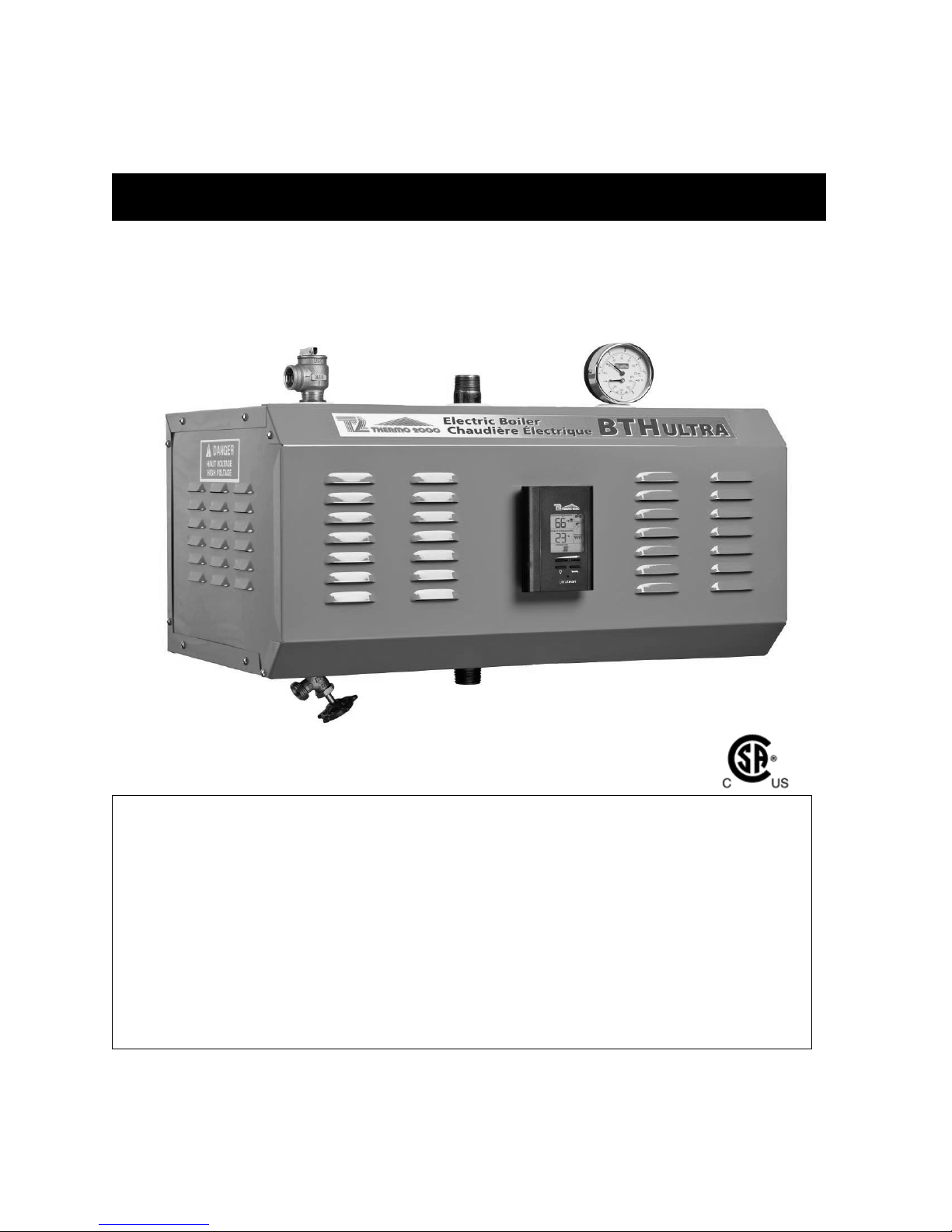
BTH ULTRA Electric Boilers
M
odels ranging from 6 kW to 33 kW :
120/240 Volts ( 1 phase )
INSTALLATION & OPERATION MANUAL
Your BTH ULTRA Electric Boiler has been carefully assembled and factory tested to provide
years of trouble-free service. The following information and safety measures are provided to
enable proper installation, operation, and maintenance of this product.
It is imperative that all persons who are expected to install, operate or adjust this boiler should
read these instructions carefully.
Any questions regarding the operation, maintenance, service or warranty of this electric boiler
should be directed to the supplier.
When all installation steps have been completed, insert this installation manual in its original
envelope, and keep in a safe place (close to the boiler) for future reference.
THERMO 2000 INC. revision : April 2011
Printed in Canada
Page 2
Section 1: DIMENSIONS AND SPECIFICATIONS
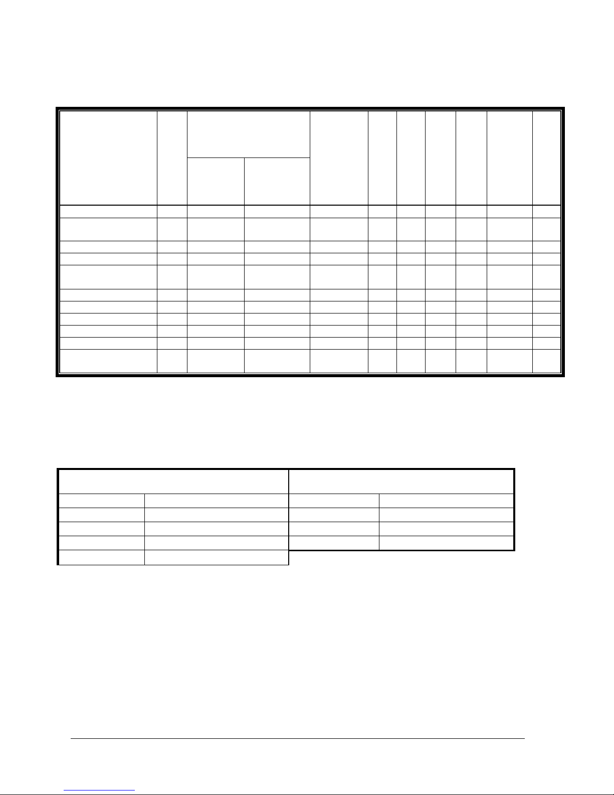
Table 1: Electric Ratings for 120/240 VAC (1 phase) Electric Boilers:
Current
Amp
Model
BTH ULTRA 6 6 25.0 30.0 2 X 3KW 2 1 1 2 8 40
BTH ULTRA 8 8 33.3 38.3
BTH ULTRA 10 10 41.6 46.6 2 X 5KW 2 1 1 2 6 60
BTH ULTRA 12 12 50.0 55.0 4 X 3KW 4 1 1 4 6 70
BTH ULTRA 15 15 62.5 67.5
BTH ULTRA 18 18 75.0 80.0 4 X 4.5KW 4 1 1 4 3 100
BTH ULTRA 20 20 83.4 88.4 4 X 5KW 4 1 1 4 3 110
BTH ULTRA 24 24 100.0 105.0 4 X 6KW 4 1 1 4 2 150
BTH ULTRA 27 27 112.5 117.5 6 X 4.5KW 4 1 2 6 1 150
BTH ULTRA 30 30 125.0 130.0 6 X 5KW 4 1 2 6 1/0 175
BTH ULTRA 33 33 138.0 143.0
*Maximum current for circulator : 5 amps. (1/6 HP Max.)
**
Models 6 to 24kW are also certified for Aluminum cables of higher gauge.
Electrical local codes may require different cable gauge.
P
KW
Heating
Elements
Total
with
Circulator
Elements
1X 3KW
1 X 5KW
2 X 3KW
2 X 4.5KW
3 X 5KW
3 X 6KW
Stages
2 1 1 2 8 50
4 1 1 4 4 100
4 1 2 6 2/0 200
Control
Electronic
Power Relays
Table 2: Connections sizes & Boiler overall dimensions
Wire**
CU
90oC
Main Contactors
Fuse
A
Connections sizes Boiler overall dimensions
Boiler Inlet 1 “ NPT M Height 12 3/16 inches
Boiler Outlet 1 “ NPT M Width 16 7/16 inches
Waterworks 1/2 “ NPT F Depth 24 ½ inches
Safety valve 3/4 “ NPT F Shipping weight 99 lbs.
Drain valve 1/2 “ NPT F
Operating temperature : from 50°F to 190°F (10 to 90C)
Maximum operating pressure: 30 psi (207kPa)
BTH ULTRA Electric Boilers USE & CARE MANUAL
(Revision April 2011), Page
2.
Page 3
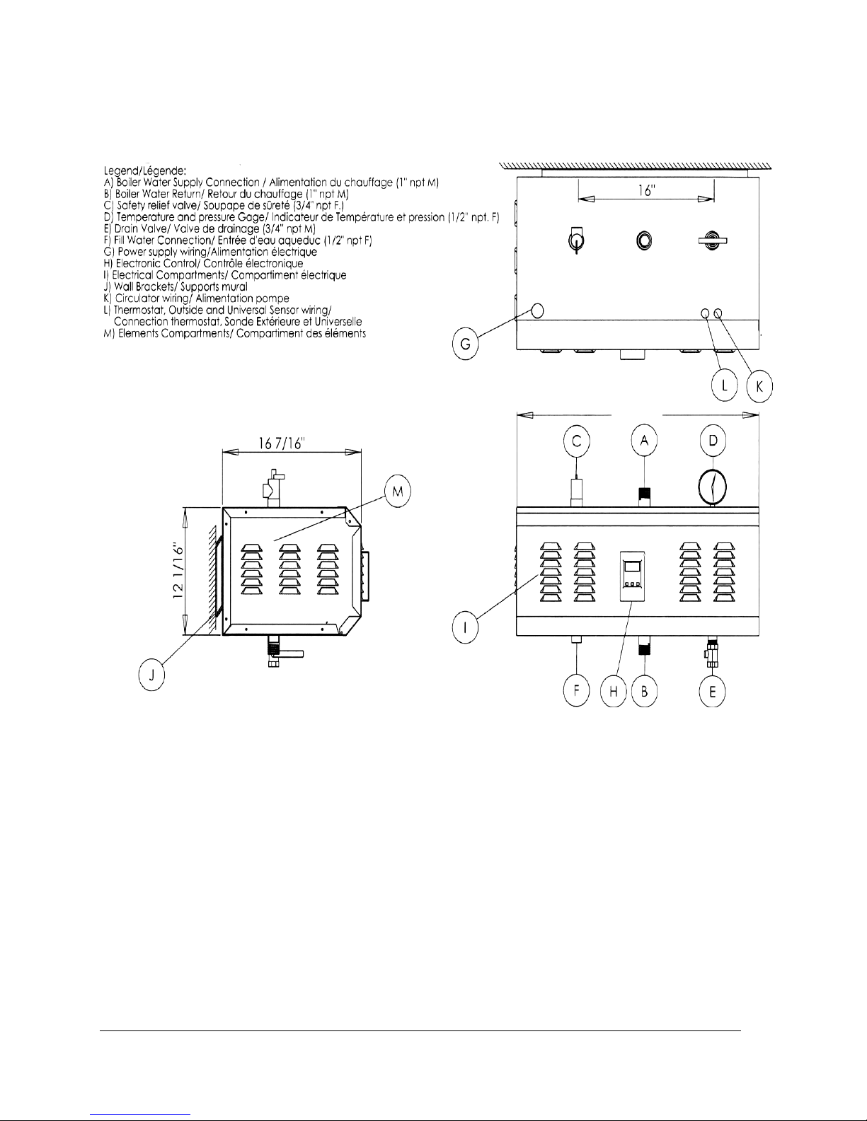
Figure 1 : Component identification
.
24 1/2"
BTH ULTRA Electric Boilers USE & CARE MANUAL
(Revision April 2011), Page
3.
Page 4
General Safety Precautions
!
Be sure to read and understand the entire Use & Care Manual before attempting to install or to
operate this electric boiler. Pay particular attention to the following General Safety Precautions.
Failure to follow these warnings could cause property damage, bodily injury or death. Should
you have any problems understanding the instructions in this manual, ask for help from
a qualified installer or technician.
Section 2: INTRODUCTION
WARNING
!
The important safeguards and instructions
appearing in this manual are not meant to
cover all possible conditions and situations
that may occur. It should be understood that
common sense, caution and care are factors
which cannot be built into every product.
They are the responsibility of the person(s)
caring for and operating the unit.
2.1 LOCAL INSTALLATION
REGULATIONS
This electric boiler must be installed in
accordance with these instructions and in
conformity with local codes, or in the absence of
local codes, with the National Plumbing Code
and the National Electric Code current edition.
In any case where instructions in this manual
differ from local or national codes, the local or
national codes take precedence.
2.2 CORROSIVE ATMOSPHERE
The electric boiler should not be located near an
air vent containing a corrosive atmosphere or
high humidity. The limited warranty is void when
the failure of the electric boiler is due to a
corrosive atmosphere.
2.3 INSPECT SHIPMENT
Inspect the electric boiler for possible shipping
damage. The manufacturer’s responsibility
ceases upon delivery of goods to the carrier in
good condition. Consignee must file any claims
for damage, shortage in shipments, or nondelivery immediately against carrier.
2.4 CHECK LIST
Please check the identification tag on the unit to
make sure you have the right model.
List of components shipped with the unit :
· Pressure relief valve set at 30 PSI.
· Drain valve.
· Outdoor temperature sensor
· Tridicator (temperature & pressure
gauge).
CAUTION !
The electric boiler should not be located in
an area where leakage of the tank or water
connections will result in damage to the
adjacent area or to lower floors of the
structure. When such areas cannot be
avoided, a suitable drain pan or nonflammable catch pan, adequately drained,
must be installed under the boiler.
The pan must be connected to a drain.
NOTE: Auxiliary catch pan MUST conform to
local codes.
BTH ULTRA Electric Boilers USE & CARE MANUAL
(Revision April 2011), Page
4.
Page 5

Section 3: INSTALLATION
WARNING
!
The manufacturer’s warranty does not cover
any damage or defect caused by installation,
or attachment, or use of any special
attachment other than those authorized by
the manufacturer into, onto, or in
conjunction with the boiler. The use of such
unauthorized devices may shorten the life of
the boiler and may endanger life and
property. The manufacturer disclaims any
responsibility for such loss or injury
resulting from the use of such unauthorized
devices
3.1 SECURITY CONSIDERATIONS
Domestic and commercial installations have a
maximum design operating pressure limited to
30 psi (207 kPa) by a safety relief valve.
This boiler is designed to operate on a closed
circuit system operating between 50 to 190°F.
This boiler is designed to be used only in a hot
water heating system.
The hi-limit control of the unit is fixed and set at
212F (100C). If the heating distribution system
on which the boiler is installed requires a hi limit
controller set at a lower temperature, this
controller will have to be added to the system
and connected in series with the hi-limit installed
at the factory.
!
The heat transfer medium must be water or
other non-toxic fluid having a toxicity rating
or class of 1, as listed in clinical Toxicology
of Commercial products, 5th edition
3.2 LOCATION
The electric boiler should be installed in a clean,
dry location. Long hot water lines should be
insulated to conserve water and energy. The
electric boiler and water lines should be
protected from exposure to freezing
temperatures.
The electric boiler must be installed horizontally,
directly on the wall or on an adequate ground
support. On wall hung applications, use the
supplied wall mounting brackets. It is held on the
wall by four 5/16’’ lag screws. The openings are
located at 16’’ intervals (i.e. standard stud
spacing). When the first bracket is installed you
can hang the boiler on the wall (see figure 1).
The lag screws must be suitably anchored to
safely support the weight of the boiler including
water content, piping and wiring.
The electric boiler must be located or protected
so as not to be subject to physical damage, for
example, by moving vehicles, area flooding, etc.
All models can be installed on combustible floors
and in alcoves. Ambient temperature must not
exceed 90°F or 32°C.
3.3 CLEARANCE
Minimum clearances for adequate inspection
and servicing are listed in the following table:
Table 3: Boiler clearance
Top & Bottom of the boiler
Front side of the boiler 24 inches
Back side of the boiler
Left side 16 inches
Right side
6 inches
6 inches
0 inch
BTH ULTRA Electric Boilers USE & CARE MANUAL
(Revision April 2011), Page
5.
Page 6
3.4 PIPING INSTALLATION
3.4.1 Type of installation
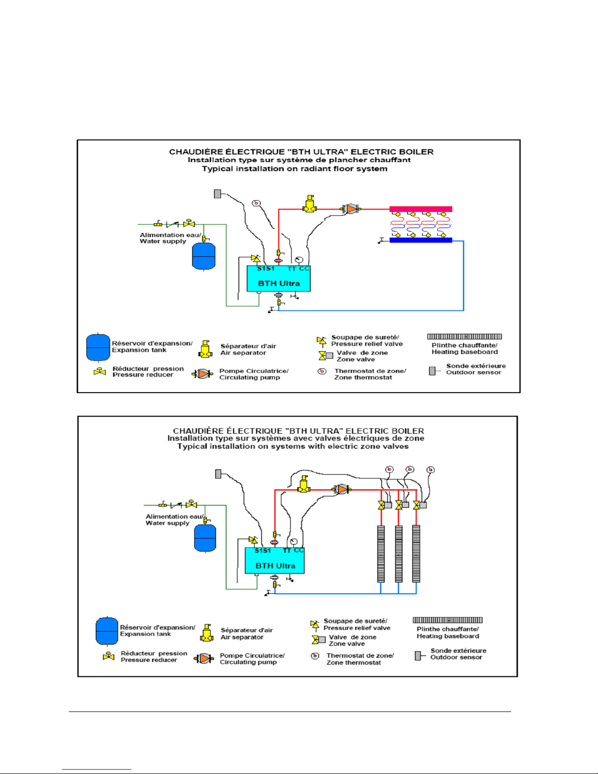
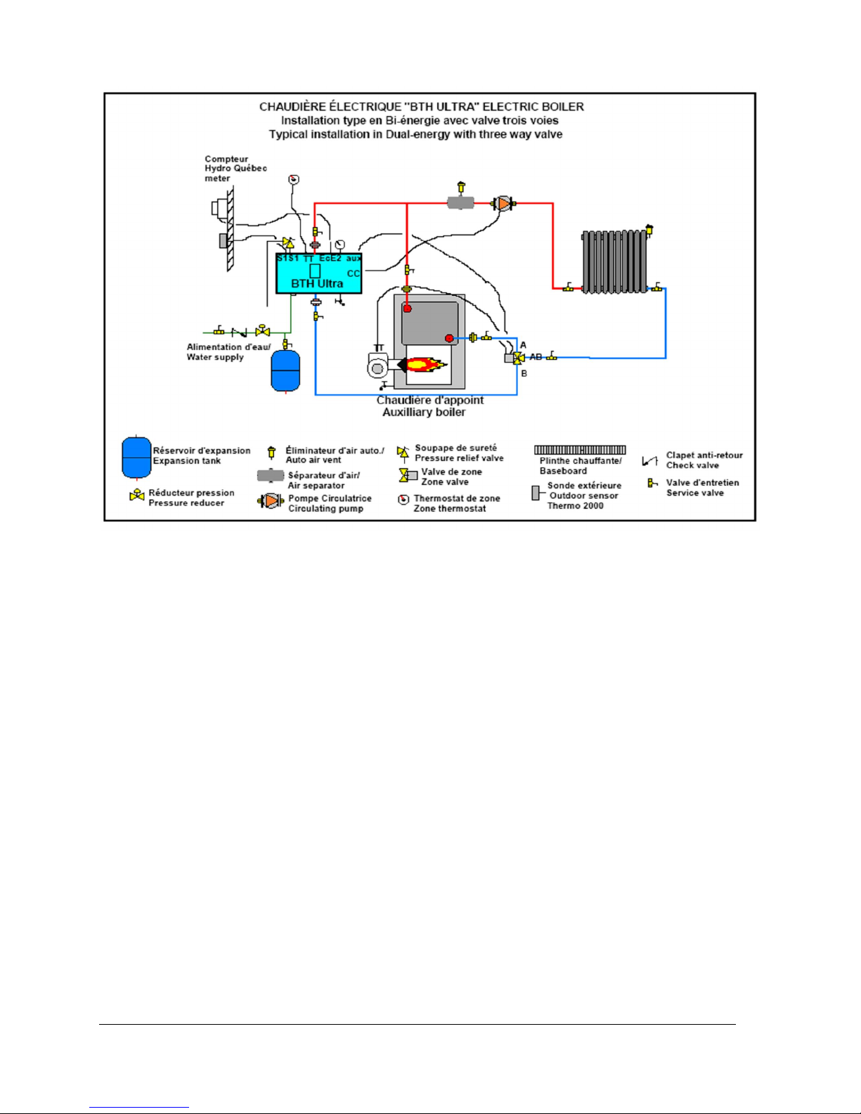
You will find below on figures 2 to 6 typical piping arrangement for the two main types of installation. The
first being as a self operating unit and the others being coonected to an auxiliary boiler in dual-energy.
Figure 2
Figure 3
BTH ULTRA Electric Boilers USE & CARE MANUAL
(Revision April 2011), Page
6.
Page 7
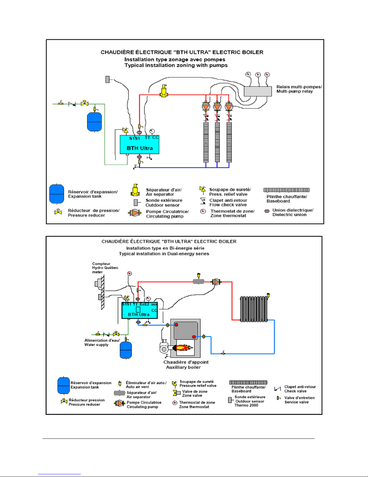
Figure 4
Figure 5
BTH ULTRA Electric Boilers USE & CARE MANUAL
(Revision April 2011), Page
7.
Page 8
.
Figure 6
3.4.2 Boiler piping
The outlet of the boiler is located on the top side,
and the inlet of the boiler is located on the bottom
side of the boiler. They are steel pipes (1”male
NPT threaded connection) where the connections
are to be made.
Installing a union is recommended on the boiler
water outlet and inlet piping to facilitate boiler
disconnection for servicing.
Dielectric unions are required for protection of the
boiler and piping if dissimilar pipe material such as
galvanized steel and copper are present.
Use only clean pipe for boiler water lines. Local
codes or regulations shall govern the exact type of
material to be used.
Insulate all pipes containing hot water, especially
in unheated areas.
Install shutoff (ball) valves for servicing
convenience.
Cap or plug unused connections on the boiler. Do
not cap the pressure relief valve on the boiler
since it will damage and shorten the life of the
boiler and may endanger life and property.
3.4.3 Pressure relief valve
An automatic pressure relief valve must be
installed during boiler setup. The pressure rating
of the relief valve must not exceed 30 psi.
Connect the outlet of the relief valve to a
discharge line going to 6” above a floor drain,
away of any live electrical parts. The discharge
line must pitch downward from the valve to allow
complete draining by gravity of the relief valve and
discharge line, and be of a diameter no smaller
than that of the valve outlet. The tip of the
discharge line should not be threaded or
concealed and should be protected from freezing.
No valve of any type, restriction or reducer
coupling should be installed on the discharge line.
Local codes shall govern the installation of relief
valves.
3.4.4 Expansion tank
The increase in boiler water volume resulting from
higher temperature is stored in the expansion tank
during periods of high operating temperature and
is returned to the system when the temperature
decreases.
BTH ULTRA Electric Boilers USE & CARE MANUAL
(Revision April 2011), Page
8.
Page 9

If it is not properly sized, the system pressure will
get above the allowable operating pressure of
30psi (207kPa) and the pressure relief valve will
open. Contact your local heating distributor for
proper selection.
3.4.5 Pressure regulator
An automatic water feeding system must be
employed as required by codes. An automatic
fill valve must be used with a backflow preventer
as required, to maintain minimum system pressure
by supplying water to make up for leakage. The
minimum usual pressure is 12psi.
3.4.6 Air bleeder
Installation of manual or automatic air vent devices
prevents air from accumulating in the system. Air
vents should be installed at all high points to
remove trapped air during initial setup and to
ensure that the system is tight. Regularly purge
the air out of the system while taking care to avoid
personal injuries or property damage caused by
hot boiler water spray.
3.4.7 Pump selection
Performance characteristics of centrifugal pumps
are described by pump curves, which plot flow
versus head of pressure together with other
information such as efficiency and power. Consult
the manufacturer’s pump curves to select the
proper model or ask your pump dealer or your
HVAC wholesaler for a recommendation.
Table below shows required flow in relation to the
power capacity of the boiler and selected
temperature drop in the heating distribution
system. On System with baseboard heaters, 20F
3.5 ELECTRIC CONNECTIONS
3.5.1 Main Electric supply
Wiring must conform to the National Electrical
Code and to state or local code requirements.
Wiring must be from a 120/240 Volt (single phase,
60 Hz) circuit protected by a properly sized
breaker. Wire gauge (3 wires+ground) must be
properly sized. Consult the boiler rating plate to
select the proper breaker and wire gage.
Models 6 to 24 kW are certified for CU/AL cables.
Aluminum cables being generally bigger than
copper.
temperature drop is normally recommended and
on radiant floor application a value of 10F is
generally used.
Table 4: Temperature rise vs flow rate (GPM)
BWTD
Model KW
o
10
20oF 30oF 40oF
F
BTH ULTRA 6
BTH ULTRA 8
BTH ULTRA 10
BTH ULTRA 12
BTH ULTRA 15
BTH ULTRA 18
BTH ULTRA 20
BTH ULTRA 24
BTH ULTRA 27
BTH ULTRA 30
BTH ULTRA 33
6 4,1 2,0 1,4 1,0
8 5,5 2,7 1,8 1,4
10 6,8 3,4 2,3 1,7
12 8,2 4,1 2,7 2,0
15 10,2 5,1 3,4 2,6
18 12,3 6,1 4,1 3,1
20 13,7 6,8 4,6 3,4
24 16,4 8,2 5,5 4,1
27 18,4 9,2 6,1 4,6
30 20,5 10,2 6,8 5,1
33 22,5 11,3 7,5 5,6
3.4.8 Dual Energy piping
Piping connections between the two boilers can be
made in parallel or in series as illustrated in fig.
5&6.
When installed in parallel, a three way motorized
valve (1”NPTF) is used to guide the heating
system return water toward the appropriate boiler
according to the operating mode in demand. This
way, the oil or gas boiler is not maintained hot by
the return water when the operation is in
Electricity.
N.B.: Make sure to select the appropriate port A, B
and AB when making the connection of the piping
(see fig.6)
3.5.2 Connecting the thermostat and
pump.
3.5.2.1 Single heating zone
Using a 18 gauge cable, connect a low voltage
thermostat to terminals T and T on the electric
panel (DO NOT apply any power to these
terminals).
Connect the pump directly to the CC 120volts
terminals of the boiler using a 14gauge cable.
N.B. The amperage drawn by the pump shall not
exceed 5A or 1/6HP
BTH ULTRA Electric Boilers USE & CARE MANUAL
(Revision April 2011), Page
9.
Page 10
A two stage thermostat could also be installed.
Then the second heating stage would be used to
activate the “Boost” program allowing the boiler
target to be gradually increased (see section
4.10).
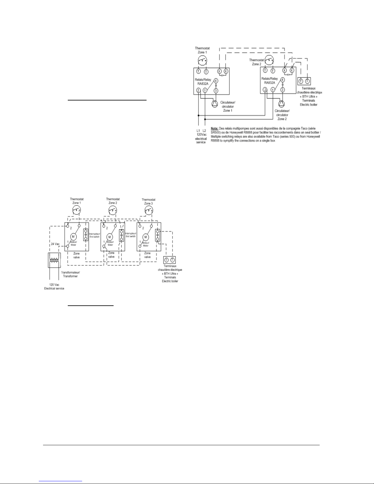
3.5.2.2 Multi-Zone systems
q Zoning with motorised valves
The components shall be connected in such a way
that when a thermostat is in demand, only the
corresponding valve opens. Connect the zone
valve end switch to terminals T and T on the
electric panel (DO NOT apply any power to
these terminals!). Proper connection of the valve
shall be made according to the manufacturer
instruction.
Connect the circulating pump to terminals CC
120v of the boiler
N.B. The amperage drawn by the pump shall not
exceed 5A or 1/6HP
Typical connection schematic below
Figure 7
q
Circulator zoning
The components shall be connected in such a way
that when a thermostat is in demand, only the
corresponding pump is activated. Connect the low
voltage thermostat to the corresponding pump
relay (Honeywell #RA-832 or multipump relay) and
connect its auxiliary dry contact to terminals T and
T on the electric panel (DO NOT apply any power
to these terminals!).
The CC120V terminals will then not be used.
N.B.: Do not install a jumper between the TT
terminals of the boiler.
Figure 8
3.5.3 Outdoor sensor
If you wish that the target boiler temperature
modulate according to the outdoor temperature
(the target temperature will increase as the
outdoor temperature drops), the supplied outdoor
sensor will need to be connected to S1S1
terminals. It will need to be connected before
applying the electrical power to the unit.
The installation of the sensor enables also to stop
the operation of the boiler when the outdoor
temperature gets to a temperature when no need
for heating is required.
If you wish to operate the boiler at a fixed
temperature set point, do not install the sensor
before applying the power to the unit.
The sensor should be located on an insulated wall
exposed to outdoor temperature. The selected
location should best reflect the heat load of the
building. Generally a North wall except on a
building having large window areas exposed to the
South where the sensor should then be located.
The sensor shall be connected to S1S1 terminals
using 18ga. wires not exceeding 200ft. Do not
apply current to these terminals.
3.5.4 Dual-energy connection with an
auxiliary boiler.
The BTH ULTRA boiler is designed to enable the
installation on Dual-energy applications without
the need to install an interface controller between
the boilers and the electricity supplier authorization
signal. Upon the reception of that signal, the BTH
ULTRA will select the appropriate heating mode
and will activate the required boiler.
If the heating distribution system is equipped with
only one pump connected to the CC terminals of
BTH ULTRA Electric Boilers USE & CARE MANUAL
(Revision April 2011), Page
10.
Page 11
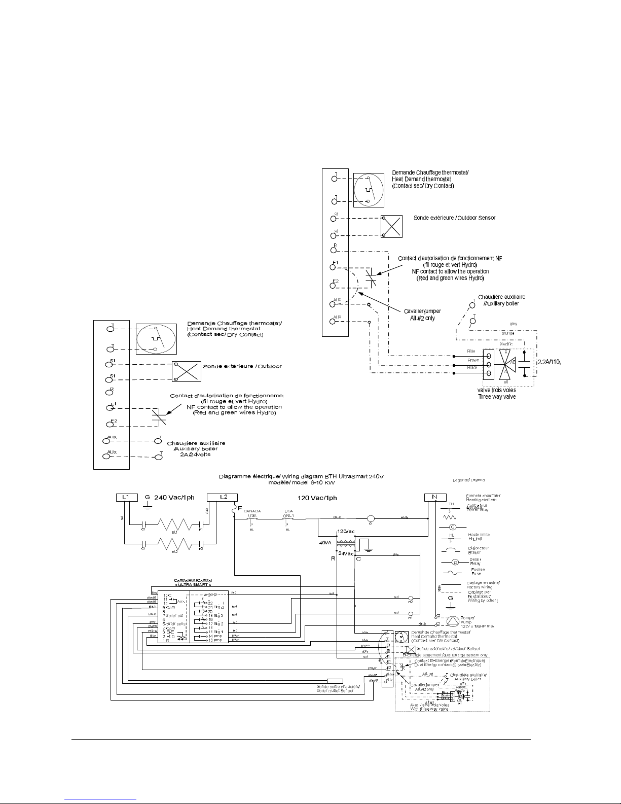
the boiler, it will be activated on heat calls from the
thermostat whatsoever the heating mode selected.
To do so,
o Open the front access panel to the boiler
electric compartment where the controller is
mounted and position the switch located on its
back at “Bi-Energ”.
o Install a 2 wire 18ga cable between the
contact (N/F close contact to allow the
operation in electricity, Red R wire and green
V wire of Hydro-Quebec) of the authorization
signal to terminals EcE2 of the electric boiler.
o If the piping installation is made as shown on
fig.5 then without three way valve, install an
18ga two wire cable between boiler terminals
“AUX” and the TT terminals of the auxiliary
boiler.
o N.B. Le capacity of the AUX contact is
2A/24Vac max.
o See the operating sequence in Dual-energy at
section 4.11.
o If the installation is made as shown on fig.6,
then with a three way valve orienting the
heating return water only in the operating
boiler: Install a three wire 18ga cable between
the valve and the electric boiler terminals.
Following this, connect the end switch of the
valve (grey and orange wire) to the TT
terminals of the auxiliary boiler.
Figure10
Figure 11
BTH ULTRA Electric Boilers USE & CARE MANUAL
(Revision April 2011), Page
11.
Page 12
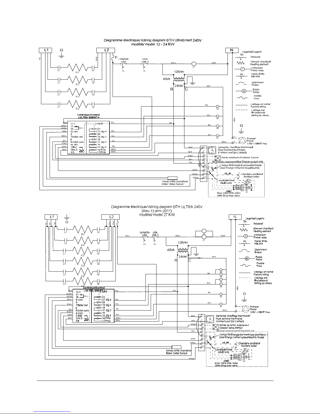
Figure 12
Figure 13
BTH ULTRA Electric Boilers USE & CARE MANUAL
(Revision April 2011), Page
12.
Page 13
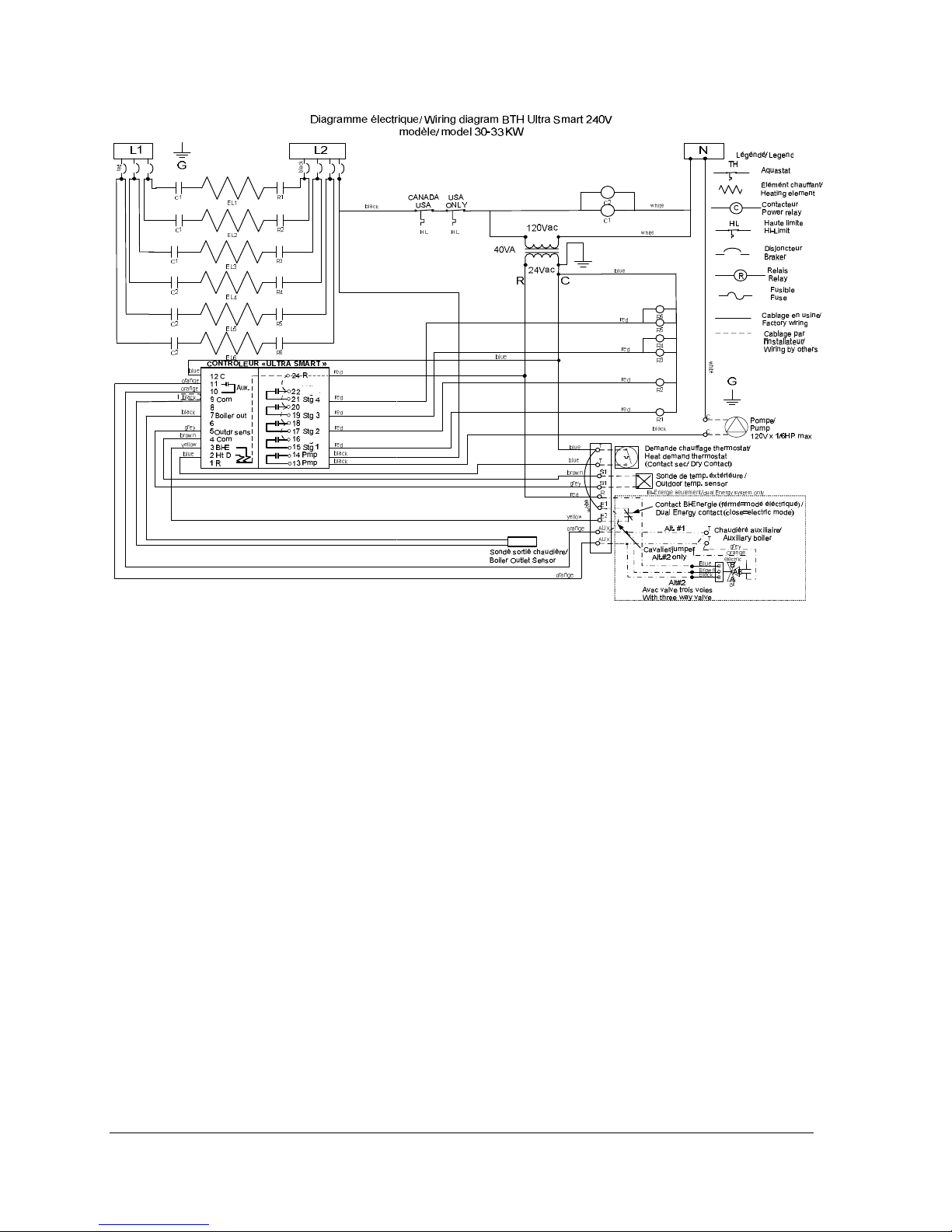
Figure 14
Section 4 : ADJUSTMENT OF THE CONTROLLER
4.1 INTRODUCTION
The BTH Ultra boiler is mainly designed to be
installed on closed circuit applications where the
water of the heating system flows directly from the
boiler to the heating distribution system (Standard
parallel Piping system)
Two operation modes are then offered:
q
Fixed boiler temperature set point (the
outdoor sensor shall not be installed)
Or
q
Outdoor reset
4.2 DISPLAYED INFORMATION
The electronic control uses an LCD display to
make all adjustments and to visualize the
operation of the system.
BTH ULTRA Electric Boilers USE & CARE MANUAL
(Revision April 2011), Page
13.
Page 14
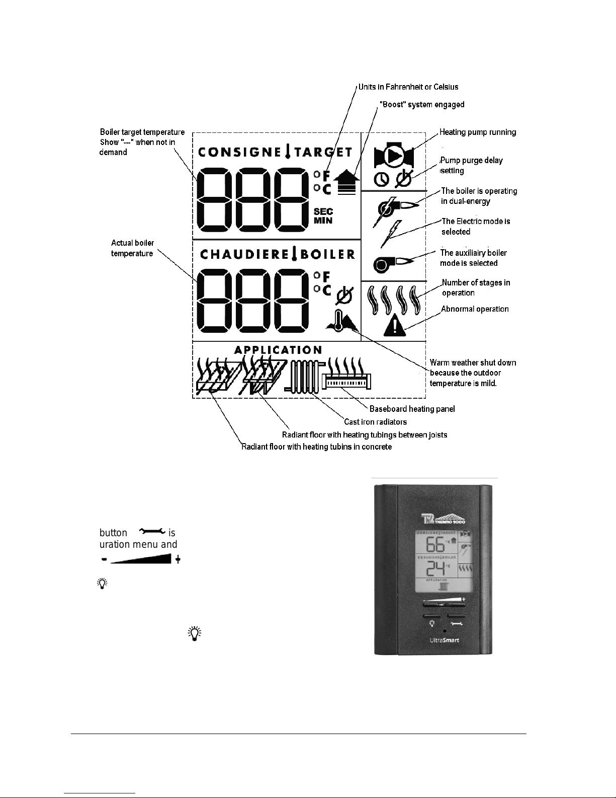
Figure 15
4.3 OPERATION OF THE INTERFACE
The controller uses four push buttons at the
bottom of the display to select and adjust the
parameters.
The button is used to access the
configuration menu and confirm a selection.
The buttons are used to
select an item or adjust a value.
The button enables the illumination of the
display under two different modes.
The default mode will enable the illumination of
the display for a period of 10 sec. each time a
button is pressed. If the is pushed, the light
will be continuously illuminated. Just press the
button to change the mode of activation.
BTH ULTRA Electric Boilers USE & CARE MANUAL
(Revision April 2011), Page
Figure 16
14.
Page 15
4.4 OPERATION IN “FIXED BOILER
TEMPERATURE SET POINT”
For installation where the boiler target
temperature shall be maintained at a fixed
temperature that will not vary in relation to the
outdoor temperature, the sequence of operation
will be as follow:
On a call for heat from the room thermostat, the
circulating pump will start and the boiler will
activate the number of stages required to get to
and maintain the outlet temperature of the boiler
near the selected target temperature. A rotation
of the stages based on an equal time period of
operation is provided.
N.B. The supplied outdoor temperature sensor
shall not be connected before applying the
electrical power to the unit
4.5 OPERATION WITH “OUTDOOR
RESET”:
For installation where the boiler target
temperature shall modulate in relation to the
outdoor temperature; when the outdoor
temperature gets colder, the boiler target
temperature will increase.
On a call from the room thermostat, the
circulating pump will start and the boiler will
activate the number of stages required to get to
and maintain the outlet boiler temperature near
the target temperature established by the
controller according to the outdoor temperature.
A rotation of the stages based on an equal time
period of operation is provided.
N.B. The supplied outdoor temperature sensor
must be connected before applying the electrical
power to the unit.
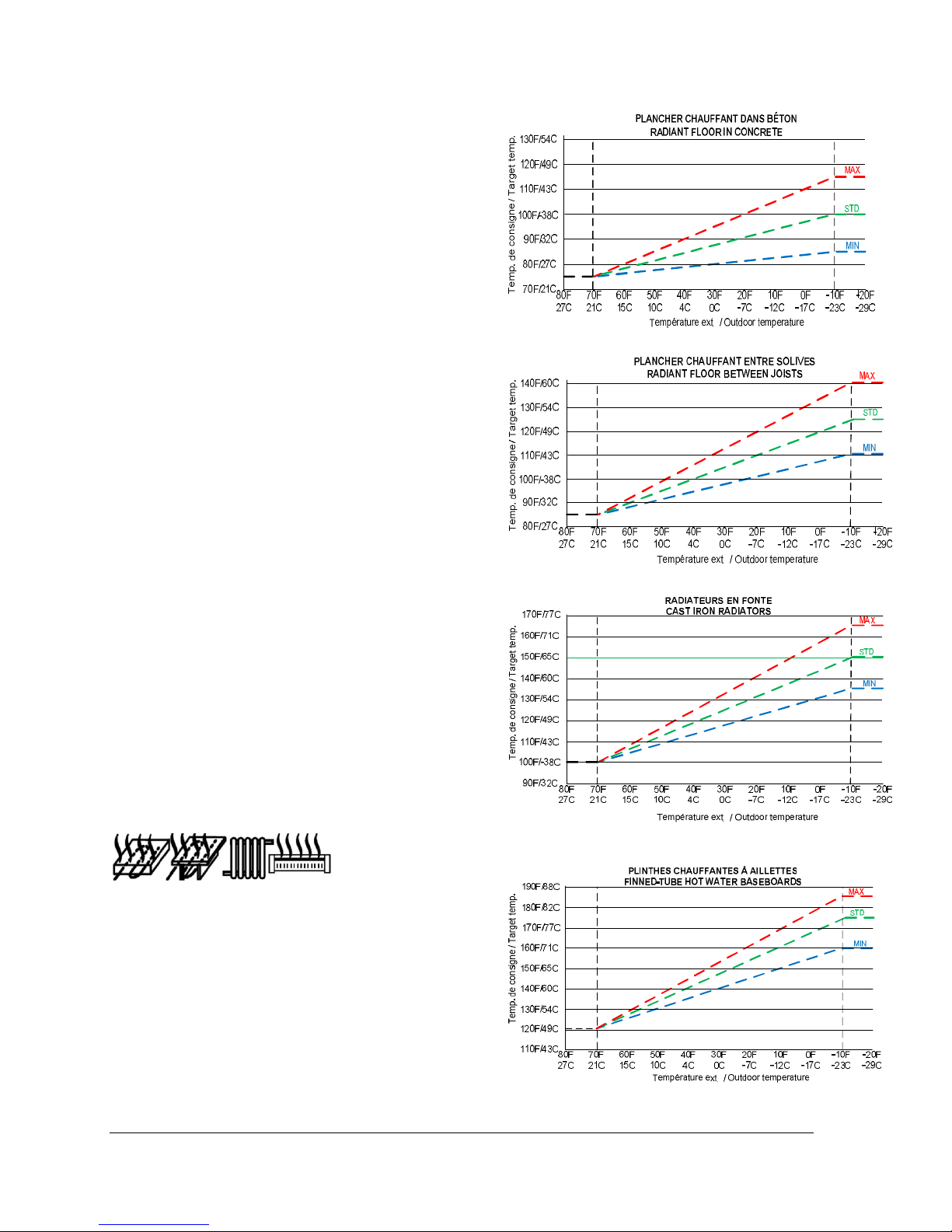
The boiler target temperature will be calculated
by the controller in relation to the parameters
selected in the menu
and the
maximum target temperature required when the
outdoor temperature will get to -10F (-23C). The
“STD” curve corresponds to the default
maximum temperature for a typical system and
this value can be modified from the “MIN” to
“MAX” value shown on the following tables.
The following tables show the values of the
target temperature that will be obtained in
relation to the outdoor temperature.
Figure 17: Radiant floor in concrete
Figure 18 : Radiant floor between joists
Figure 19 : Cast iron radiators
Figure 20 : Hot water baseboards
BTH ULTRA Electric Boilers USE & CARE MANUAL
(Revision April 2011), Page
15.
Page 16
4.6 PURGE DELAY OF THE PUMP
The controller offers the possibility to
stop the operation of the pump after an
adjustable delay once the heat demand has
been completed.
The following choices are offered:
-“OFF” The pump will stop immediately when the
heat demand has been satisfied. This selection
shall be selected on systems equipped with
motorised fast closing zone valves in order to
prevent noise from water hammering.
-“15 sec to 60 min” delay where the pump will
be kept running to enable the pump to circulate
water into the system to equilibrate the heat in
all the building.
-“ON” The pump is in continuous operation.
Required on particular heating distribution
systems.
4.7 AUTOMATIC HEATING
SHUT DOWN
When the outdoor sensor is installed and the
unit then operates in the “outdoor reset” mode,
the controller offers the user the possibility to
automatically stop the boiler when the outdoor
temperature reaches an adjustable value (0F (17C) à 105F (40C). This characteristic is
especially interesting on the following
applications:
-Heating systems equipped with many
thermostats where the user wants to prevent the
operation of the unit if one of the thermostats
has inadvertently been activated.
-Heating systems where the owner supplies heat
to a lodger
-Systems connected to a geothermic heat pump
where we do not want the electric boiler to be
operating unless the outdoor temperature drops
to a selected degree.
4.8 CONFIGURATION OF THE CONTROLLER
Since each type of heating distribution system is
designed to operate at water temperatures that
are particular to its operation, the proper
configuration of the operating parameters of this
particular system is important to maximize its
performance.
In order to do this, the installer will first have to
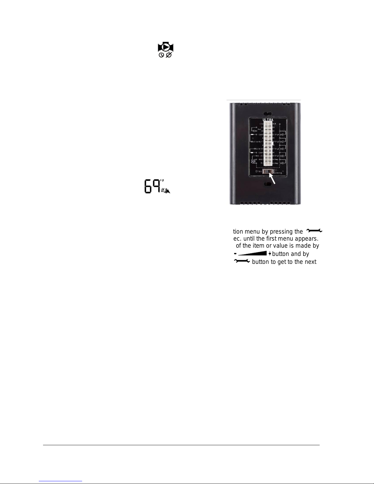
tell the controller if the application is in Dualenergy with an auxiliary boiler. The selection is
made by selecting the position “Elect.” Or “BiEnerg” on the switch located at the back of the
controller. This selection will have to be made
before applying voltage to the unit. The default
setting is “Elect.”
Figure 21
This being done, the installer will have to access
the configuration menu by pressing the
button for 2 sec. until the first menu appears.
The selection of the item or value is made by
pressing the button and by
pressing the button to get to the next
menu. See table 1 below to visualize the menu
list that will gradually be displayed.
If the buttons remain untouched for a period of
10 sec., the controller will register the value of
the selection made and return to the regular
display position. It will also return to the regular
display after reviewing all the operating
parameters of the controller.
In case of a power failure, the parameters will be
restored as they were established before the
failure.
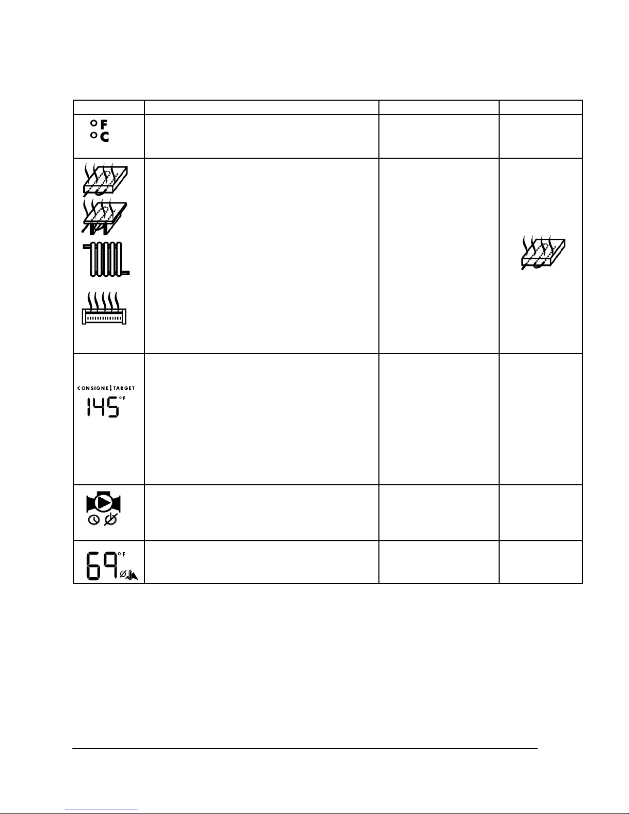
Table 5 below shows the presentation sequence
of the menus.
BTH ULTRA Electric Boilers USE & CARE MANUAL
(Revision April 2011), Page
16.
Page 17
Cast iron radiator
85à 105F
ts 110Fà140F
Table 5 :
ITEM DESCRIPTION RANGE DEFAULT
Choose the units the user prefers to work with F0 or C0 F0
-Radiant Floor in
concrete
-Radiant Floor between
joists
Select the type of heating system on which the
boiler will be installed.
-
Hot water baseboards
-Radiant Floor in
concrete
Adjust the maximum boiler target temperature
required to adequately heat the building when the
outdoor temperature is very cold.
-Radiant Floor between
jois
-Cast iron radiator 135F
100F
125F
150F
à 165F
-Baseboard
Select the purge period that the pump will be
running once the heat demand is completed.
Select OFF if the heat system is equipped with
electric zone valves.
Select the outdoor temperature at which no
heating of the building is required (the outdoor
160F à 185F
OFF
15 sec. to 60min.
ON
0F à 105F 75F
175F
30sec
sensor has to be installed)
Note 1: Once the operating parameters have been set, the controller will automatically come back to
normal display screen. If the user needs to increase or decrease the target temperature, he can do it
without having to enter in the configuration menu (see the following section)
BTH ULTRA Electric Boilers USE & CARE MANUAL
(Revision April 2011), Page
17.
Page 18
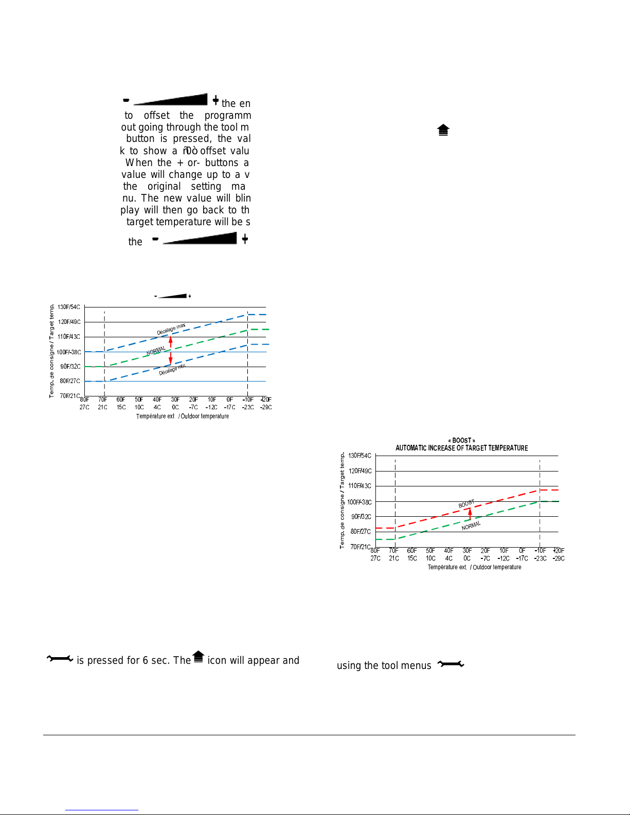
4.9 ADJUSTMENTS OF THE TARGET
TEMPERATURE BY THE USER:
By pressing the the end user has
the possibility to offset the programmed target
temperature without going through the tool menus.
When the + or- button is pressed, the value “0” will
appear and blink to show a “0” offset value from the
original settings. When the + or- buttons are pressed
again the offset value will change up to a value of + 10F(5C) from the original setting made in the
configuration menu. The new value will blink during 5
sec. and the display will then go back to the standard
view and the new target temperature will be shown.
Afterward, when the button will
be pressed, it will show the value of the offset made
previously and can be re-adjusted.
OPERATION OF THE + - BUTTONS
Figure 22
4.10 BOOST SYSTEM OPERATION
The controller incorporates a unique feature that
enables the target boiler temperature to automatically
be increased when the building heat load increases but
cannot be fulfilled with the actual boiler target
temperature and consequently the room thermostat(s)
cannot be satisfied within a pre-determined period.
Example:
-Return to normal heat load after low demand periods
occurring during sunny days.
-Long periods without heating which needs higher boiler
temperature to recuperate.
-Return to normal room temperature after thermostat’s
“nights set back” program.
Three “Boost” operating options are available when the
is pressed for 6 sec. The icon will appear and
the three options ON1, ON2 and OFF will be proposed.
Press the + - button to select. The controller will register
the selected item and will return to normal operation
after 5 sec.
Operation in “Boost” Option ON1
(default setting)
The controller will engage the “Boost” program when
the heat demand on terminals TT has been maintained
for a pre-determined period according to the type of
selected application. Once this period has been
reached, the “Boost” icon will appear on the display
and the boiler target temperature will start increasing
very slowly over a pre-determined period and up to a
pre-calculated maximum value until the heat demand
applied on TT terminals has been completed.
On a new heat demand, the previous boost period is
forgotten and the boiler target gets back to its original
setting
Operation in “Boost” Option ON2 (only offered on
installation not operating in Dual-energy)
The boost program is a marvellous feature that works
fine on applications where the number of room
thermostats is in limited quantity otherwise it may
happen that during very cold periods the heat demand
from all the thermostats may not become satisfied.
This option requires the installation of one or two stages
heating thermostats. The second stage of the
thermostat(s) will have to be connected to Ec-E2 of the
boiler and the option ON2 selected.
Then the Boost mode will be instantaneously started
increasing the target temperature when the signal from
the second heating stage will be received. The target
temperature will immediately start increasing.
Figure 23
N.B. If the system is in “boost” most of the time, this
means that the boiler target parameter established
during “Setting procedure” would be too low for the
heating system on which the unit is applied. This boiler
target could simply be gradually increased by pressing
the + button or by re-setting the operating parameters
using the tool menus .
The Boost menu can be cancelled by selecting “OFF” in
the Boost menu.
BTH ULTRA Electric Boilers USE & CARE MANUAL
(Revision April 2011), Page
18.
Page 19
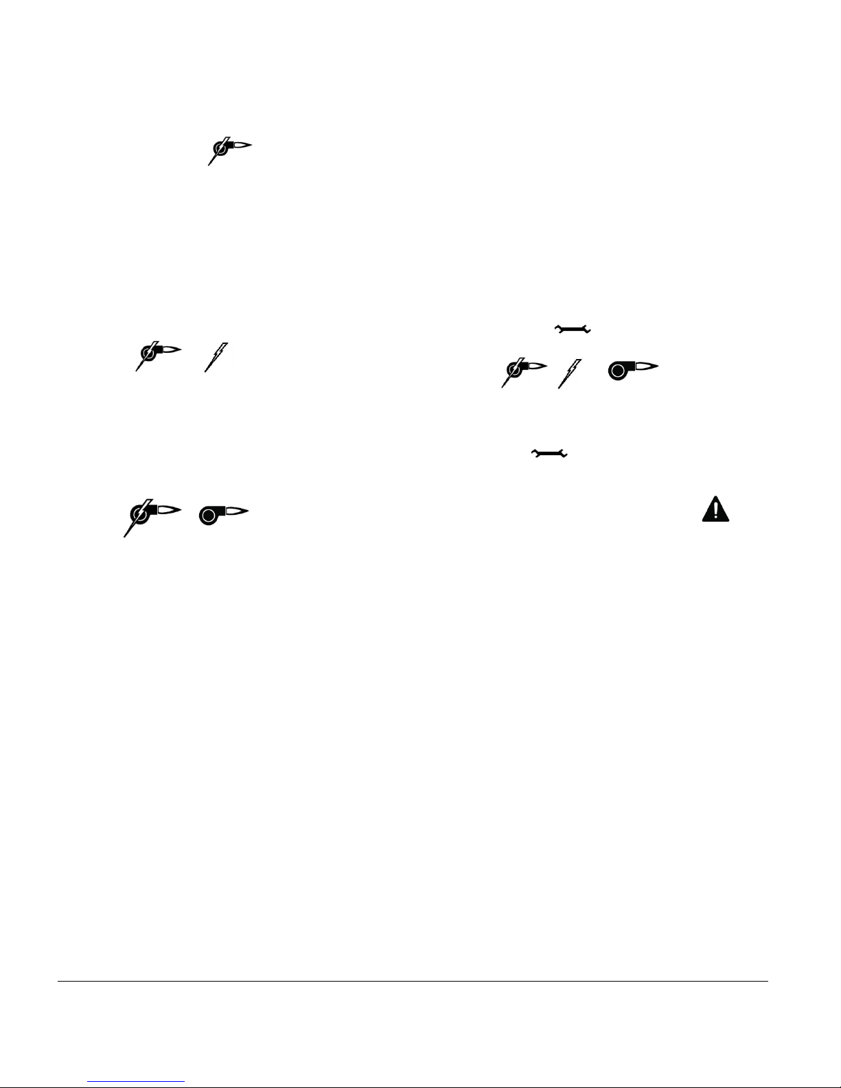
4.11 OPERATION IN DUAL-ENERGY:
In Dual-energy mode, the display will indicate that this
mode is active in showing the icon
If it is not shown, check the position of the switch
located at the back of the controller. It must be set to
“Bi-Energ” position.
N.B. The controller will have to be reset to register the
new mode of operation. Just turn the power OFF and
back ON to the unit.
Operation in Dual-energy with Electric
When the authorisation signal to operate in electricity is
received, (close contact between Ec&E2), the following
icons will be shown.
The circulating pump and the heating elements will be
activated according to the operating parameters
established earlier.
Operation in Dual-energy with the auxiliary boiler
When the authorisation signal will be absent (open
contact between Ec&E2), the following icons will be
shown.
terminals and when the auxiliary boiler temperature will
be lower than the settings of its own temperature
controls.
If a three way valve is used on the piping as shown in
fig.6, it will change position when the contact will close
on AUX terminals and it will be the end switch of the
valve that will give the signal to the auxiliary boiler to
come on. The water flow will then circulate only in the
auxiliary boiler.
Manual selection for the electricity or auxiliary
boiler mode.
If the user wishes to manually select the electricity or
auxiliary boiler operation, it can be done in following the
sequence below:
o Push on the button for 6 sec. and the
following icons will appear
The selection of the dual-energy or electric only or
auxiliary boiler only is made with the + - button. Once
the selection has been made it will be registered by
pressing the or by waiting for 5sec.
If the electricity only or auxiliary boiler only has been
Upon reception of a heat demand on terminals TT of
BTH ULTRA boiler, terminals C1&C2 will be energized
at 120volts and the pump will be activated. At the same
time, the contact will close on the “AUX” terminals to
activate the auxiliary boiler. This boiler will be activated
only when there will be a heat demand to the TT
selected, the corresponding icon and the icons will
blink to advise the user that an unusual heating mode
has been selected.
BTH ULTRA Electric Boilers USE & CARE MANUAL
(Revision April 2011), Page
19.
Page 20

Section 5: START UP OPERATION
SAFETY PRECAUTIONS
!
Before operating this boiler, be sure to read and
follow these instructions, as well as the warnings
printed in this manual. Failure to do so can result in
unsafe operation of the boiler resulting in property
damage, bodily injury, or death. Should you have
any problems reading, following or difficulty in
understanding the instructions in this manual,
STOP, and get help from a qualified person.
Do not turn on the boiler unless it is filled with
water. Do not turn on the boiler if the cold water
supply shut-off valve is closed.
5.1 PREPARATORY STEPS
q
Make sure that all the piping and electrical
connections have been made.
q
Fill the boiler and the heating system with
water.
q
Check for leaks.
q
Check the pressure reading at the temperature
and pressure indicator. It should be around
12psi.
q
Turn On the electrical supply to the boiler with
no heat demand from the thermostat(s).
q
Completely eliminate all the air from the boiler
and the distribution piping system. To do so,
activate the circulating pump without the
heating elements. If the pump is connected
directly on CC terminals of the boiler, it can be
activated by selecting “ON” in the configuration
menu after having pressed
q
Adjust the UltraSmart boiler temperature
controller as explained earlier and set the purge
delay of the pump to its normal operation
setting.
5.2 START UP
q
Set the room thermostat ON to generate a heat
demand. The pump shall start. The heating
elements shall gradually come on and the boiler
temperature will increase.
N.B. A rapid check of the operation of all the boiler
components could be made by pressing simultaneously
the + and- buttons of the controller and maintaining
them pressed until all the components have come ON.
q
Measure the amperage value drawn by the unit.
It shall be around the value indicated on the
boiler name plate.
q Partially close the isolating valve at the outlet
of the boiler to reduce the water flow and
consequently slowly increase the outlet
temperature. The heating elements shall
gradually stop as the temperature increase and
gets near the target temperature.
q Lower the adjustment of the room thermostat(s)
the heating elements shall stop and the pump
shall stop after the delay set on the controller.
q Check the pressure reading on the gauge of the
unit. It should not be higher than 28psi when
the distribution system reaches its maximum
operating temperature. If the pressure gets to
that value, it may be because the expansion
tank is not large enough for the application.
5.3 COMPLEMENTARY CHECKS ON DUALENERGY INSTALLATIONS
q
Check the proper operation of the authorization
signal to operate on electricity or auxiliary in
simulating the operation of the signal on Ec and
E2 and verifying the change of the operating
mode.
N.B. On initial start up it may take a considerable
amount of time before the water reaches the target
temperature
Further adjustments may be necessary as you use your
boiler and the space heating system.
BTH ULTRA Electric Boilers USE & CARE MANUAL
(Revision April 2011), Page
20.
Page 21

Section 6 MAINTENANCE
6.1 INTRODUCTION
Properly maintained, your boiler will provide years of
dependable, trouble free service. It is recommended
that a regular routine maintenance program be
established and followed by the user. Components are
subject to eventual failure that requires service. Failure
to use the correct procedures or parts in these
circumstances may make the unit unsafe or reduce the
life of the boiler.
The owner should have the following inspection and
maintenance procedures performed:
6.2 AT ALL TIME
An immediate inspection shall be made if:
q An odor of melted plastic or overheated
material is detected
q A leak coming from the unit or the heating
system is observed
If a leak is detected at the outlet of the safety relief
valve, it could be related to a problem with components
installed on your heating distribution system. A quick
correction is then required.
Do not plug the outlet of this valve if a dripping condition
occurs.
6.3 TWICE A YEAR
q
Check for the proper operation of the automatic
air purger(s) and eliminate air from the
radiators.
6.4 ANNUALY
WARNING
Make sure that the power on the unit has been
turned off before opening the electrical
compartments of the boiler.
q Open the boiler drain valve to eliminate
!
deposits that could have settled at the bottom of
the boiler. Stop when water gets clear. If there
is no flow or a very small flow, it could be due to
a large accumulation of deposits at the bottom
of the unit. If so, close the isolating valves at the
inlet and outlet of the boiler, remove heating
element(s) and clean the inside of the tank with
a strong jet of water
It is recommended that a visual inspection be made on
the electrical compartments of the boiler to check the
water tightness of the gasket on the element flange and
also check for any signs of overheating of the
components and wires. At the beginning of the heating
season, check the proper operation of the
operating/safety controls, circulating pump and heating
distribution system components. Required corrections
should be made as soon as possible. Parts used for
replacement shall be the same as the original
equipment.
BTH ULTRA Electric Boilers USE & CARE MANUAL
(Revision April 2011), Page
21.
Page 22
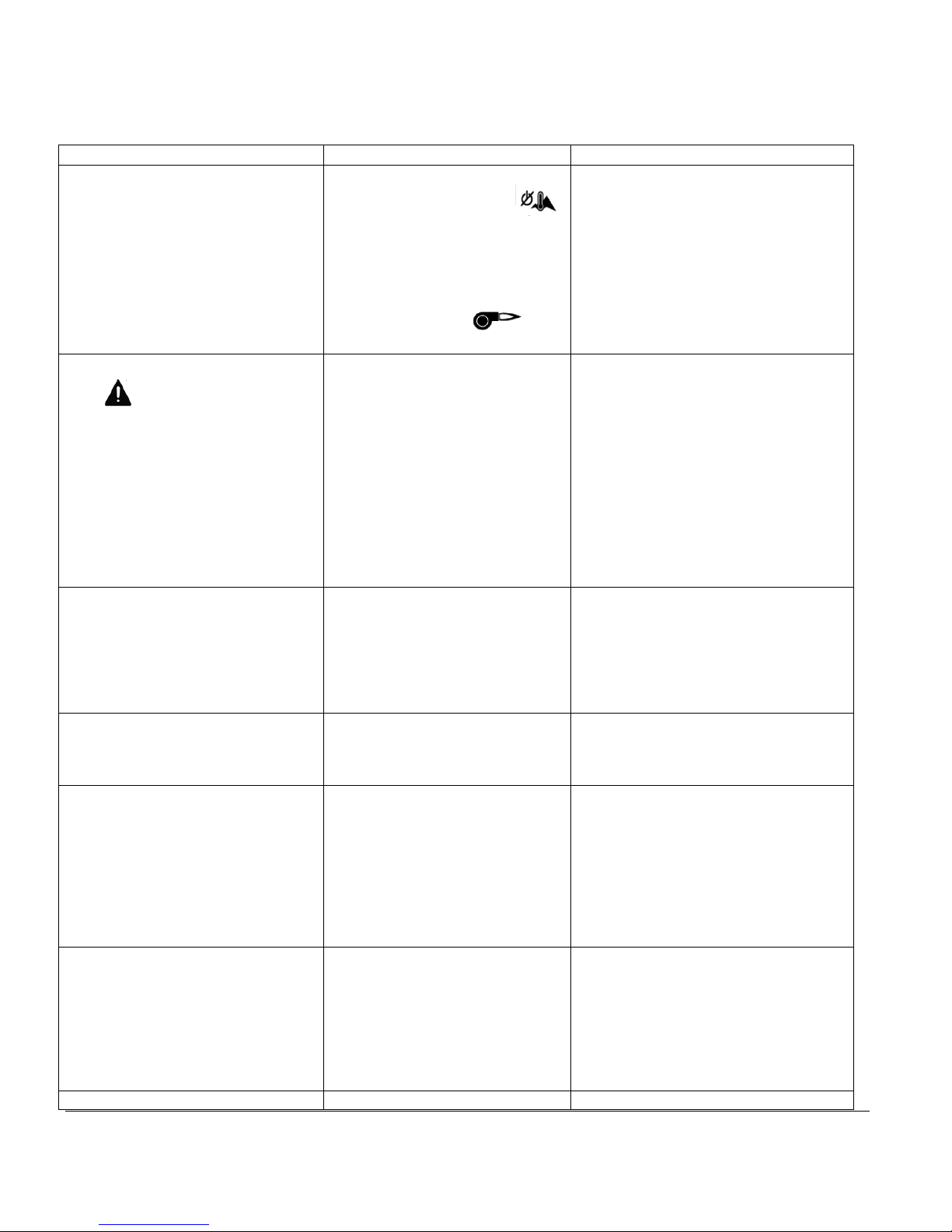
Section 7- TROUBLE SHOOTING
7.1 TROUBLE SHOOTING TABLE
PROBLEM CAUSES SOLUTION
The display shows
TEMP”
The display shows
icon is displayed.
The display shows “Er2” and blinks The circuit of the temperature
Stage 2 is ON but not Stage 1 There is no problem. A rotation
The boiler water temperature at the
outlet of the unit “BOIL OUT” does
not get to the “BOIL TARGET”
temperature.
Boiler stays in demand even when
the thermostat is not in demand.
(Systems with only one thermostat)
Boiler stays in demand even when -On systems with electric zone -Change defective “end switch”.
BTH ULTRA Electric Boilers USE & CARE MANUAL
---
in “TARGET
“Er1”
and the
-There is no heating demand
when the outdoor sensor
is used and the icon is
shown, the outside temperature
is above the boiler shut down
setting.
-The switch located on the back
of the controller is set to “Bi-
Energ” and the icon is
shown.
The controller is not detecting the
presence of the outdoor sensor.
sensor corresponding to the
displayed information is open.
of the stages is provided to allow
an equal time of operation of the
stages
-The room thermostat is not in
constant demand.
-Some heating elements are
defective
-The heating distribution system
is using the total capacity of the
boiler at an equilibrium
temperature lower than the boiler
target temperature
The electronic thermostat used is
not fully compatible with the
boiler.
(Revision April 2011), Page
-Generate a heat demand
-Temporarily increase the value of this
setting on the controller configuration.
-Set the switch to “Elect”
-Make sure that the sensor cable
connected to the unit is not in short or
open circuit. Do not install a jumper
between S1-S1 when the sensor is
not required.
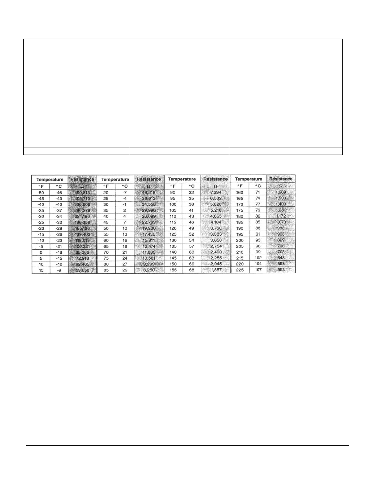
-Check the resistance value (ohms) of
the sensor. It should correspond to the
value shown on the table below
otherwise it should be replaced.
Check for proper connection of the
wires inside the boiler connected to
S1S1 and at the controller terminals.
-Select the appropriate heating mode
(modes 2,3,5&5 require an additional
sensor)
-Make sure that the required sensor is
properly connected to corresponding
terminals and that the cable used is
not damaged.
-Adjust the thermostat anticipator (If
available) to obtain longer operating
cycles
-Replace defective elements
-If a higher boiler water temperature is
required to satisfy the heat demands
of the thermostats, a boiler having a
larger capacity is required.
Add a 1000ohms x 1 watt resistor in
parallel with the demand circuit and
the common. We can provide (at no
cost) a kit with required material.
-Replace existing thermostat with a
model having a dry contact so that no
current can leak to the boiler controller
22.
Page 23
the thermostat is not in demand.
(Systems with more than one
thermostat)
An overheated plastic odour is
released from the boiler
Boiler safety valve is leaking -Pressure reading at the indicator
valves, one or many end
switches included in the valve is
defective.
-A jumper has been installed on
terminals TT of the boiler
Turn the power OFF to the boiler.
Open the front and left side panel
of the boiler. Check the
components and electric wires
for indications of overheating.
shows a pressure above 28psi
-Pressure is below 28psi
-Make appropriate connections as
shown in fig.14
Replace overheated components and
check supply voltage to the boiler.
-The pressure regulator on the
distribution system is defective or the
expansion tank is too small or
defective.
-Replace the safety valve
Table 6: Resistance value of the outdoor sensor vs outdoor temperature
BTH ULTRA Electric Boilers USE & CARE MANUAL
(Revision April 2011), Page
23.
Page 24

BTH ULTRA LIMITED WARRANTY
Warranty Coverage for Residential Installation.
Thermo 2000 Inc. hereby warrants to the original residential purchaser that the BTH
ULTRA tank installed in a residential setting shall be free of leaks during normal use
and service for a period of ten (10) years from the date of purchase as long as the
original residential purchaser owns the home in which the unit was originally
installed, the first (5) years in full and years six (6) through ten (10) prorated 20%
each year at suggested retail price. Residential setting shall mean usage in a singlefamily dwelling in which the consumer resides on a permanent basis. Also,
residential setting shall mean use in multiple family dwellings in which one (1) BTH
ULTRA tank is to be used in only one (1) dwelling. In the event that a leak should
develop and occur within this limited warranty period due to defective material or
workmanship, such leak having been verified by an authorized company
representative, Thermo 2000 inc. will repair or replace at our sole discretion the
failed unit with the nearest comparable model at the time of replacement.
The original residential purchaser is responsible for all costs associated with the
removal and reinstallation, shipping and handling to and from manufacturing plant.
The replacement unit will be warranted for the remaining portion of the original
Warranty.
Warranty Coverage for Commercial Installation.
Thermo 2000 Inc. warrants to the original purchaser that the BTH ULTRA tank
installed in a commercial setting shall be free of leaks during normal use and service
for a period of ten (10) years from the date of purchase, the first (5) years in full and
years six (6) through ten (10) prorated 20% each year at suggested retail price
Commercial setting shall mean use in other than residential setting stated above in
the residential setting definition. In the event that a leak should develop and occur
within this limited warranty period due to defective material or workmanship, such
leak having been verified by an authorized company representative, Thermo 2000
inc. will repair or replace at our sole discretion the failed unit with the nearest
comparable model at the time of replacement.
The original purchaser is responsible for all costs associated with the removal and
reinstallation, shipping and handling to and from Manufacturer. The replacement
unit will be warranted for the remaining portion of the original Warranty.
Limited two years warranty on all BTH ULTRA
components & parts
All other BTH ULTRA components & parts are warranted for a period of two (2)
years against defects due to defective material or workmanship. The original
purchaser is responsible for all costs associated with the removal and reinstallation,
shipping and handling to and from Manufacturer. The components, repaired or
replaced are warranted for the residual period of the initial warranty on the unit.
Exclusions.
This warranty is void and shall not apply if:
1. Defects or malfunctions resulting from installation, repair, maintenance and/or usage
that are not done in conformity with the manufacturer’s installation manual; or
2. Defects or malfunctions resulting from installation, maintenance, or repair that are
not done in accordance with regulations in force; or
3. Defects or malfunctions resulting from improper installation, maintenance or repair
done carelessly or resulting from consumer damage (improper maintenance,
misuse, abuse, accident or alteration); or
4. Installation in which a relief valve (pressure) is not installed or if it is not functioning
properly, or when it is not connected to a drain to avoid damage to the property; or
5. Installation in which liquid circulating in the tank does not remain in closed circuit or
installation in which piping is leaking; or
6. A polybutylene pipe or radiant panel installation without an oxygen absorption
barrier is used; or
7. Installation where the acidity of water is not within the normal Environmental
Protection Agency (EPA) (between pH 6.5 – 8.5) guidelines or the domestic water
contains abnormal levels of particulate matter or water exceeding 10.5 gpg; or
8. Your home contains any type of water softener system and the unit is not installed
and maintained in accordance with the manufacturer specifications; or
9. The BTH ULTRA unit has been subject to non authorized modifications; or
10. Defects or malfunction resulting from storing or handling done elsewhere than
Thermo 2000’s manufacturing plant; or
11. Units on which the serial number is removed or obliterated.
Limitations.
Thermo 2000 shall not be responsible for any damage, loss, and inconvenience of any
nature whatsoever, directly or indirectly, relating to the breakdown or malfunction of the
unit. This warranty limits its beneficiary’s rights. Nevertheless, the beneficiary may have
other rights, which vary from state to state.
This warranty replaces any other expressed or implicit warranty and constitutes the sole
obligation of Thermo 2000 towards the consumer. The warranty does not cover cost of
removal, reinstallation or shipping to repair or replace the unit, nor administration fees
incurred by the original consumer purchaser.
Thermo 2000 reserves its rights to make changes in the details of design, construction, or
material, as in its judgment constitute an improvement of former practices.
This warranty is valid only for installations made within the territorial limits of Canada and
the United States.
Warranty service procedure
Only authorized BTH ULTRA dealers are permitted to perform warranty obligations. The
owner or its contractor must provide Thermo 2000’s head office or authorized depot with
the defective unit together with the following information: BTH ULTRA model and serial
number, copy of the original sales receipt and owner’s identification certificate.
BTH ULTRA Electric Boilers USE & CARE MANUAL
THERMO 2OOO INC.
500, 9th Avenue, Richmond (Qc) Canada J0B 2H0
Phone: (819) 826-5613 Fax: (819) 826-6370
www.thermo2000.com
(Revision April 2011), Page
24.
 Loading...