

THERMO 2000 BTH ULTRA 12, BTH ULTRA 18, BTH ULTRA 10, BTH ULTRA 8, BTH ULTRA 15 Installation & Operation Manual
...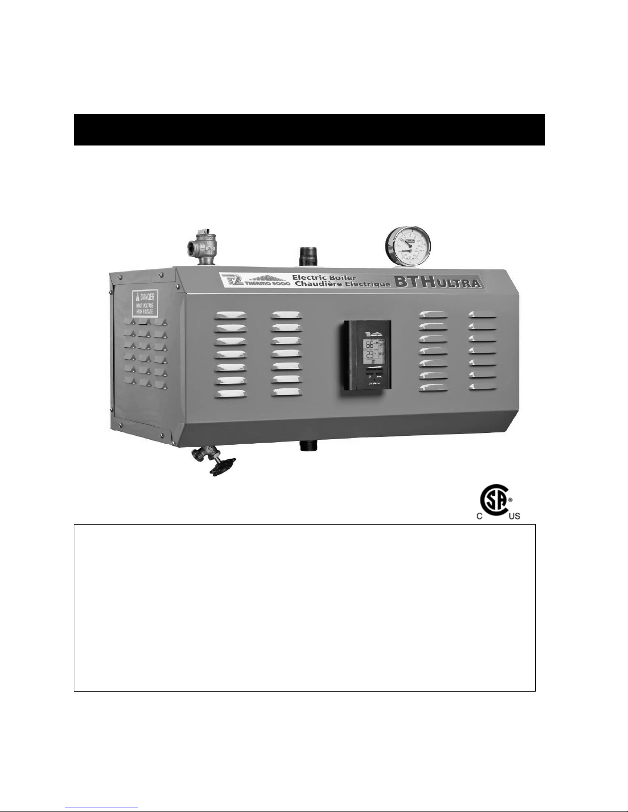
BTH ULTRA Electric Boilers
M
odels ranging from 6 kW to 33 kW :
120/240 Volts ( 1 phase )
INSTALLATION & OPERATION MANUAL
Your BTH ULTRA Electric Boiler has been carefully assembled and factory tested to provide
years of trouble-free service. The following information and safety measures are provided to
enable proper installation, operation, and maintenance of this product.
It is imperative that all persons who are expected to install, operate or adjust this boiler should
read these instructions carefully.
Any questions regarding the operation, maintenance, service or warranty of this electric boiler
should be directed to the supplier.
When all installation steps have been completed, insert this installation manual in its original
envelope, and keep in a safe place (close to the boiler) for future reference.
THERMO 2000 INC. revision : April 2011
Printed in Canada

Section 1: DIMENSIONS AND SPECIFICATIONS
Table 1: Electric Ratings for 120/240 VAC (1 phase) Electric Boilers:
Current
Amp
Model
BTH ULTRA 6 6 25.0 30.0 2 X 3KW 2 1 1 2 8 40
BTH ULTRA 8 8 33.3 38.3
BTH ULTRA 10 10 41.6 46.6 2 X 5KW 2 1 1 2 6 60
BTH ULTRA 12 12 50.0 55.0 4 X 3KW 4 1 1 4 6 70
BTH ULTRA 15 15 62.5 67.5
BTH ULTRA 18 18 75.0 80.0 4 X 4.5KW 4 1 1 4 3 100
BTH ULTRA 20 20 83.4 88.4 4 X 5KW 4 1 1 4 3 110
BTH ULTRA 24 24 100.0 105.0 4 X 6KW 4 1 1 4 2 150
BTH ULTRA 27 27 112.5 117.5 6 X 4.5KW 4 1 2 6 1 150
BTH ULTRA 30 30 125.0 130.0 6 X 5KW 4 1 2 6 1/0 175
BTH ULTRA 33 33 138.0 143.0
*Maximum current for circulator : 5 amps. (1/6 HP Max.)
**
Models 6 to 24kW are also certified for Aluminum cables of higher gauge.
Electrical local codes may require different cable gauge.
P
KW
Heating
Elements
Total
with
Circulator
Elements
1X 3KW
1 X 5KW
2 X 3KW
2 X 4.5KW
3 X 5KW
3 X 6KW
Stages
2 1 1 2 8 50
4 1 1 4 4 100
4 1 2 6 2/0 200
Control
Electronic
Power Relays
Table 2: Connections sizes & Boiler overall dimensions
Wire**
CU
90oC
Main Contactors
Fuse
A
Connections sizes Boiler overall dimensions
Boiler Inlet 1 “ NPT M Height 12 3/16 inches
Boiler Outlet 1 “ NPT M Width 16 7/16 inches
Waterworks 1/2 “ NPT F Depth 24 ½ inches
Safety valve 3/4 “ NPT F Shipping weight 99 lbs.
Drain valve 1/2 “ NPT F
Operating temperature : from 50°F to 190°F (10 to 90C)
Maximum operating pressure: 30 psi (207kPa)
BTH ULTRA Electric Boilers USE & CARE MANUAL
(Revision April 2011), Page
2.
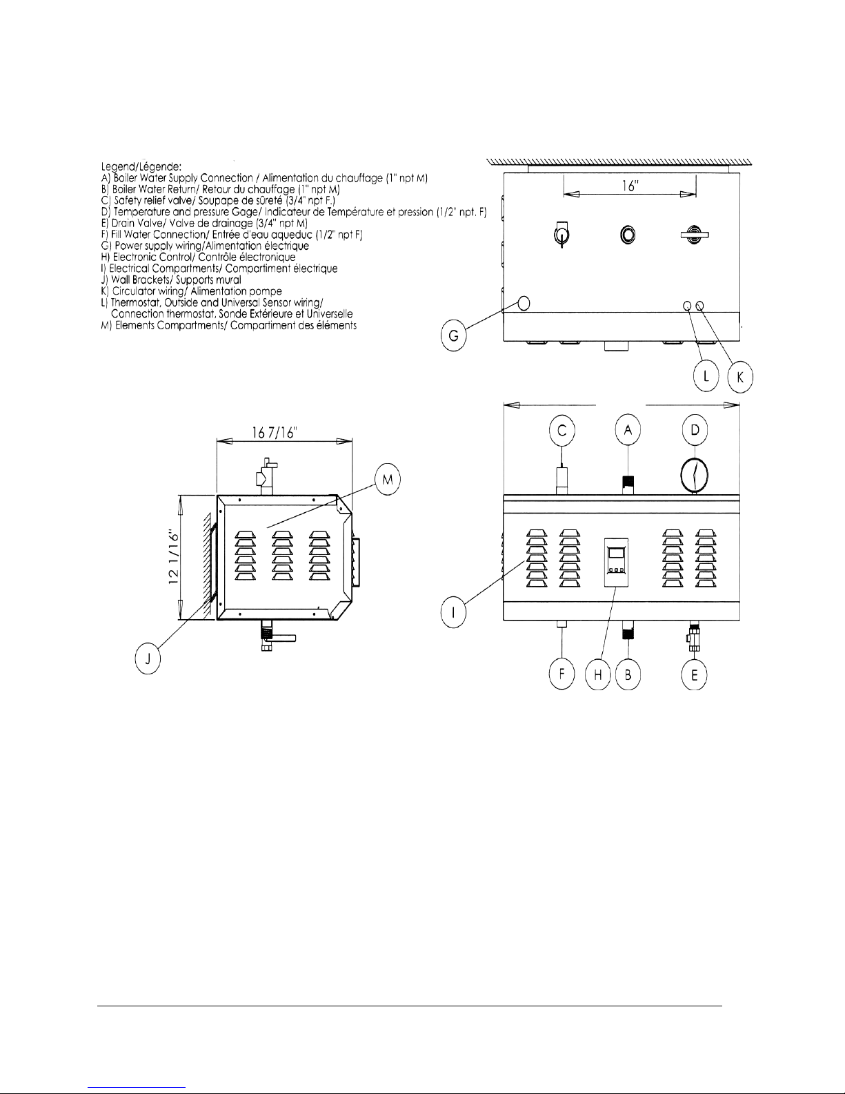
Figure 1 : Component identification
.
24 1/2"
BTH ULTRA Electric Boilers USE & CARE MANUAL
(Revision April 2011), Page
3.
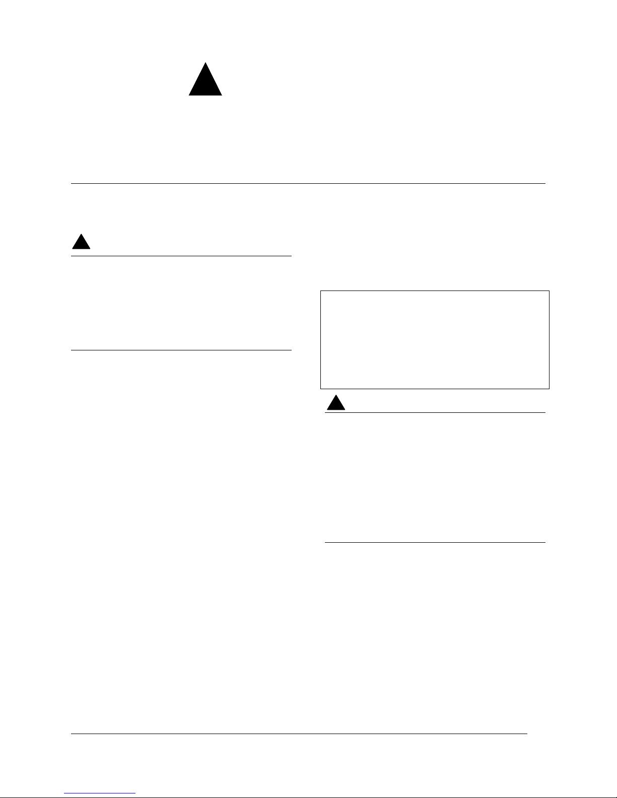
General Safety Precautions
!
Be sure to read and understand the entire Use & Care Manual before attempting to install or to
operate this electric boiler. Pay particular attention to the following General Safety Precautions.
Failure to follow these warnings could cause property damage, bodily injury or death. Should
you have any problems understanding the instructions in this manual, ask for help from
a qualified installer or technician.
Section 2: INTRODUCTION
WARNING
!
The important safeguards and instructions
appearing in this manual are not meant to
cover all possible conditions and situations
that may occur. It should be understood that
common sense, caution and care are factors
which cannot be built into every product.
They are the responsibility of the person(s)
caring for and operating the unit.
2.1 LOCAL INSTALLATION
REGULATIONS
This electric boiler must be installed in
accordance with these instructions and in
conformity with local codes, or in the absence of
local codes, with the National Plumbing Code
and the National Electric Code current edition.
In any case where instructions in this manual
differ from local or national codes, the local or
national codes take precedence.
2.2 CORROSIVE ATMOSPHERE
The electric boiler should not be located near an
air vent containing a corrosive atmosphere or
high humidity. The limited warranty is void when
the failure of the electric boiler is due to a
corrosive atmosphere.
2.3 INSPECT SHIPMENT
Inspect the electric boiler for possible shipping
damage. The manufacturer’s responsibility
ceases upon delivery of goods to the carrier in
good condition. Consignee must file any claims
for damage, shortage in shipments, or nondelivery immediately against carrier.
2.4 CHECK LIST
Please check the identification tag on the unit to
make sure you have the right model.
List of components shipped with the unit :
· Pressure relief valve set at 30 PSI.
· Drain valve.
· Outdoor temperature sensor
· Tridicator (temperature & pressure
gauge).
CAUTION !
The electric boiler should not be located in
an area where leakage of the tank or water
connections will result in damage to the
adjacent area or to lower floors of the
structure. When such areas cannot be
avoided, a suitable drain pan or nonflammable catch pan, adequately drained,
must be installed under the boiler.
The pan must be connected to a drain.
NOTE: Auxiliary catch pan MUST conform to
local codes.
BTH ULTRA Electric Boilers USE & CARE MANUAL
(Revision April 2011), Page
4.

Section 3: INSTALLATION
WARNING
!
The manufacturer’s warranty does not cover
any damage or defect caused by installation,
or attachment, or use of any special
attachment other than those authorized by
the manufacturer into, onto, or in
conjunction with the boiler. The use of such
unauthorized devices may shorten the life of
the boiler and may endanger life and
property. The manufacturer disclaims any
responsibility for such loss or injury
resulting from the use of such unauthorized
devices
3.1 SECURITY CONSIDERATIONS
Domestic and commercial installations have a
maximum design operating pressure limited to
30 psi (207 kPa) by a safety relief valve.
This boiler is designed to operate on a closed
circuit system operating between 50 to 190°F.
This boiler is designed to be used only in a hot
water heating system.
The hi-limit control of the unit is fixed and set at
212F (100C). If the heating distribution system
on which the boiler is installed requires a hi limit
controller set at a lower temperature, this
controller will have to be added to the system
and connected in series with the hi-limit installed
at the factory.
!
The heat transfer medium must be water or
other non-toxic fluid having a toxicity rating
or class of 1, as listed in clinical Toxicology
of Commercial products, 5th edition
3.2 LOCATION
The electric boiler should be installed in a clean,
dry location. Long hot water lines should be
insulated to conserve water and energy. The
electric boiler and water lines should be
protected from exposure to freezing
temperatures.
The electric boiler must be installed horizontally,
directly on the wall or on an adequate ground
support. On wall hung applications, use the
supplied wall mounting brackets. It is held on the
wall by four 5/16’’ lag screws. The openings are
located at 16’’ intervals (i.e. standard stud
spacing). When the first bracket is installed you
can hang the boiler on the wall (see figure 1).
The lag screws must be suitably anchored to
safely support the weight of the boiler including
water content, piping and wiring.
The electric boiler must be located or protected
so as not to be subject to physical damage, for
example, by moving vehicles, area flooding, etc.
All models can be installed on combustible floors
and in alcoves. Ambient temperature must not
exceed 90°F or 32°C.
3.3 CLEARANCE
Minimum clearances for adequate inspection
and servicing are listed in the following table:
Table 3: Boiler clearance
Top & Bottom of the boiler
Front side of the boiler 24 inches
Back side of the boiler
Left side 16 inches
Right side
6 inches
6 inches
0 inch
BTH ULTRA Electric Boilers USE & CARE MANUAL
(Revision April 2011), Page
5.
3.4 PIPING INSTALLATION
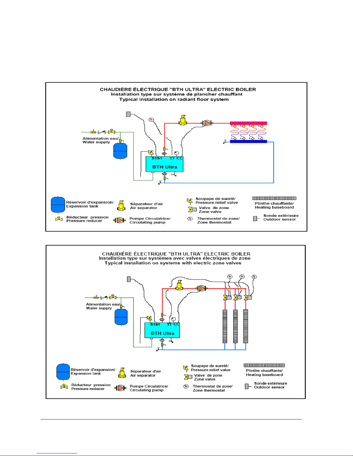
3.4.1 Type of installation
You will find below on figures 2 to 6 typical piping arrangement for the two main types of installation. The
first being as a self operating unit and the others being coonected to an auxiliary boiler in dual-energy.
Figure 2
Figure 3
BTH ULTRA Electric Boilers USE & CARE MANUAL
(Revision April 2011), Page
6.
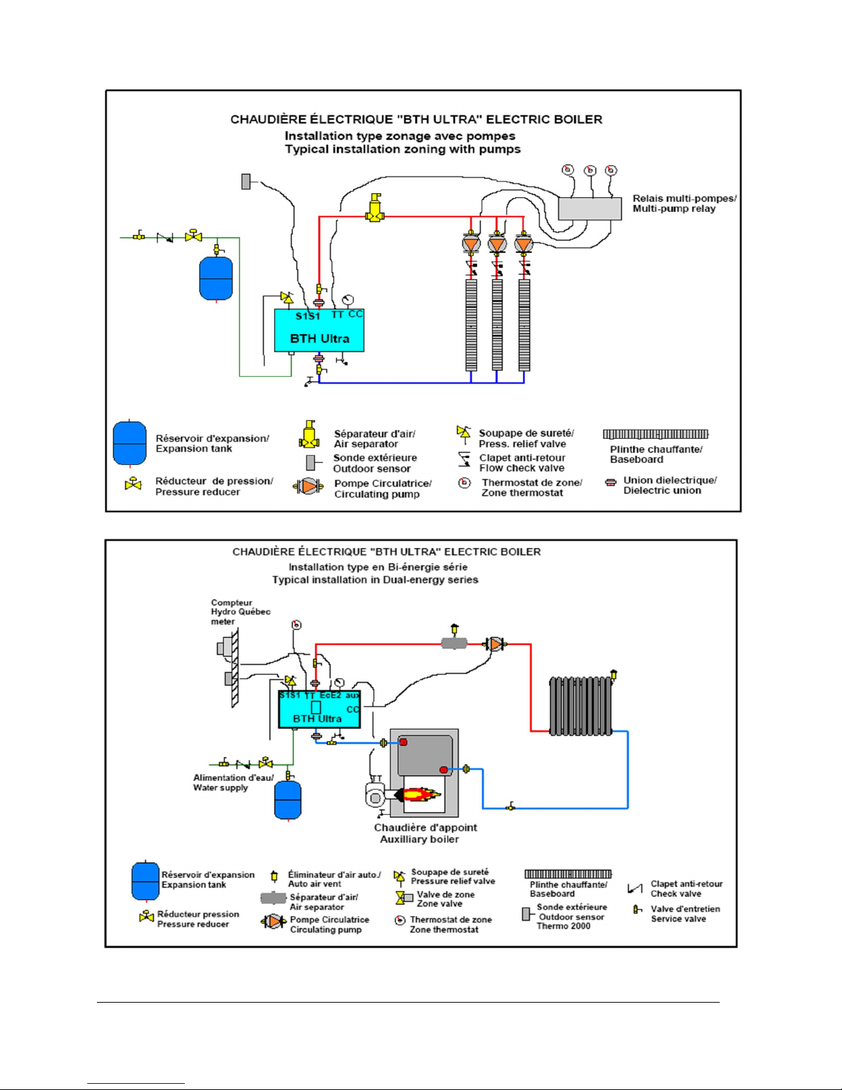
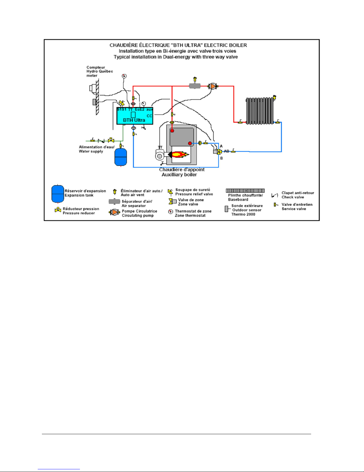
Figure 4
Figure 5
BTH ULTRA Electric Boilers USE & CARE MANUAL
(Revision April 2011), Page
7.
.
Figure 6
3.4.2 Boiler piping
The outlet of the boiler is located on the top side,
and the inlet of the boiler is located on the bottom
side of the boiler. They are steel pipes (1”male
NPT threaded connection) where the connections
are to be made.
Installing a union is recommended on the boiler
water outlet and inlet piping to facilitate boiler
disconnection for servicing.
Dielectric unions are required for protection of the
boiler and piping if dissimilar pipe material such as
galvanized steel and copper are present.
Use only clean pipe for boiler water lines. Local
codes or regulations shall govern the exact type of
material to be used.
Insulate all pipes containing hot water, especially
in unheated areas.
Install shutoff (ball) valves for servicing
convenience.
Cap or plug unused connections on the boiler. Do
not cap the pressure relief valve on the boiler
since it will damage and shorten the life of the
boiler and may endanger life and property.
3.4.3 Pressure relief valve
An automatic pressure relief valve must be
installed during boiler setup. The pressure rating
of the relief valve must not exceed 30 psi.
Connect the outlet of the relief valve to a
discharge line going to 6” above a floor drain,
away of any live electrical parts. The discharge
line must pitch downward from the valve to allow
complete draining by gravity of the relief valve and
discharge line, and be of a diameter no smaller
than that of the valve outlet. The tip of the
discharge line should not be threaded or
concealed and should be protected from freezing.
No valve of any type, restriction or reducer
coupling should be installed on the discharge line.
Local codes shall govern the installation of relief
valves.
3.4.4 Expansion tank
The increase in boiler water volume resulting from
higher temperature is stored in the expansion tank
during periods of high operating temperature and
is returned to the system when the temperature
decreases.
BTH ULTRA Electric Boilers USE & CARE MANUAL
(Revision April 2011), Page
8.
 Loading...