

THERMO 2000 BTH ULTRA 12, BTH ULTRA 15, BTH ULTRA 20, BTH ULTRA 18, BTH ULTRA 24 Installation & Operation Manual
...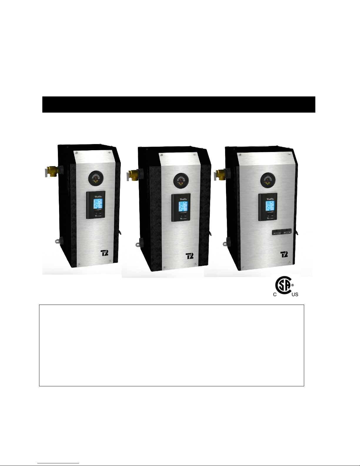
Electric Boilers
Models ranging from 12 kW to 36 kW 208/240 Volts (1 phase)
Your BTH ULTRA Electric Boiler has been carefully assembled and factory tested to provide
years of trouble-free service. The following information and safety measures are provided to
enable proper installation, operation, and maintenance of this product.
It is imperative that all persons who are expected to install, operate or adjust this boiler should
read these instructions carefully.
Any questions regarding the operation, maintenance, service or warranty of this electric boiler
should be directed to the supplier.
When all installation steps have been completed, keep this installation manual in a safe place
(close to the boiler) for future reference.
BTH ULTRA
INSTALLATION & OPERATION MANUAL
THERMO 2000 INC. Revision : June 2015
Printed In Canada

Table des matières
Section 1: Technical specifications ............................................................................................................... 4
Table 1: Technical data on boilers operating at 240 Vac /1ph1 : .................................................................. 4
Table 2 : Boiler connections and dimensions (12-24 KW) ............................................................................ 5
Table 3 : Boiler connections and dimensions (27-36 KW) ............................................................................ 5
Section 2: INTRODUCTION .......................................................................................................................... 6
2.1 LOCAL INSTALLATION REGULATIONS .......................................................................................... 6
2.2 CORROSIVE ENVIRONMENT........................................................................................................... 6
2.3 INSPECTION UPON RECEPTION .................................................................................................... 6
2.4 TO BE CHECKED .............................................................................................................................. 6
Section 3: INSTALLATION............................................................................................................................ 7
3.1 SAFETY MEASURES ......................................................................................................................... 7
3.2 LOCATION.......................................................................................................................................... 7
3.3 CLEARANCES ................................................................................................................................... 7
Table 4: Boiler Clearances ............................................................................................................................ 7
3.4 PIPING INSTALLATION ..................................................................................................................... 8
3.4.1 Type of installation ...................................................................................................................... 8
3.4.2 Boiler piping connection ............................................................................................................ 11
Local codes may dictate the type of pipe to be used for the connections.......................................... 11
Install isolating valves to facilitate maintenance ................................................................................. 11
3.4.3 Pressure relief valve .................................................................................................................. 11
3.4.4 Expansion tank .......................................................................................................................... 11
3.4.5 Water pressure regulator ........................................................................................................... 11
3.4.6 Air eliminator.............................................................................................................................. 11
3.4.7 Circulating pump ....................................................................................................................... 11
Table 5: Temperature rise vs flow rate (GPM) ............................................................................................ 11
3.4.8 Drain valve ................................................................................................................................. 11
3.4.9 Strainer ...................................................................................................................................... 11
3.4.10 Dual Energy piping .................................................................................................................. 12
3.5 ELECTRIC CONNECTIONS ............................................................................................................ 12
3.5.1 Main Electric supply .................................................................................................................. 12
3.5.2 Electrical supply of External accessories .................................................................................. 13
3.5.3 Outdoor temperature sensor ..................................................................................................... 13
3.5.4 Connecting the thermostat and pump. ...................................................................................... 13
3.5.4 Dual-energy connection with an auxiliary boiler. ....................................................................... 14
Section 4: ADJUSTMENT OF THE CONTROLLER ................................................................................... 16
4.1 INTRODUCTION .............................................................................................................................. 16
4.2 DISPLAYED INFORMATION ........................................................................................................... 16
4.3 OPERATION OF THE INTERFACE ................................................................................................. 17
4.4 OPERATION IN “FIXED BOILER TEMPERATURE SET POINT” ................................................... 17
4.5 OPERATION WITH “OUTDOOR RESET”: ...................................................................................... 17
4.6 PURGE DELAY OF THE PUMP ...................................................................................................... 18
4.7 AUTOMATIC HEATING SHUT DOWN ............................................................................................ 18
4.8 CONFIGURATION OF THE CONTROLLER .................................................................................... 18
4.9 ADJUSTMENTS OF THE TARGET TEMPERATURE BY THE USER: ........................................... 20
4.10 BOOST SYSTEM OPERATION ..................................................................................................... 20
4.11 OPERATION IN DUAL-ENERGY: .................................................................................................. 21
Section 5: START UP OPERATION ........................................................................................................... 22
5.1 PREPARATORY STEP .................................................................................................................... 22
5.2 STARTUP & INSPECTION ............................................................................................................... 22
5.3 COMPLEMENTARY CHECKS ON DUAL-ENERGY INSTALLATIONS .......................................... 22
BTH ULTRA Electric Boilers Installation & Operation manual (Revision: June 2015) 2

Section 6 MAINTENANCE .......................................................................................................................... 23
6.1 INTRODUCTION .............................................................................................................................. 23
6.2 AT ALL TIMES .................................................................................................................................. 23
6.3 TWICE A YEAR ................................................................................................................................ 23
6.4 ANNUALY ......................................................................................................................................... 23
Section 7- TROUBLE SHOOTING .............................................................................................................. 24
7.1 TROUBLE SHOOTING TABLE ........................................................................................................ 24
7.2 SPARE PARTS ................................................................................................................................. 26
BTH ULTRA LIMITED WARRANTY ............................................................................................................ 29
Figure 1 : Boiler dimensions (12-24 KW) ...................................................................................................... 5
Figure 2 : Boiler dimensions (27-36 KW) ...................................................................................................... 5
Figure 3 : Mounting positions ........................................................................................................................ 8
Figure 4 : Typical Installation on heating floor .............................................................................................. 8
Figure 5 : Typical installation on fin-tube baseboards with zoning valves .................................................... 9
Figure 6 : Multi-pump zoning......................................................................................................................... 9
Figure 7 : Typical Installation in Dual-Energy Series .................................................................................. 10
Figure 8 : Typical installation with three way valve ..................................................................................... 10
Figure 9 : Zoning with Multiple pumps ........................................................................................................ 13
Figure 10 : Zoning with motorized valves ................................................................................................... 14
Figure 11 Connexions without three way valve ......................................................................................... 14
Figure 12 : Connexions with three way valve ............................................................................................. 14
Figure 13 : Wiring diagram (12-24 KW) ...................................................................................................... 15
Figure 14 : Wiring diagram (27-36 KW) ...................................................................................................... 15
Figure 15 : UltraSmart Controller Display ................................................................................................... 16
Figure 16 : UltraSmart Control Module ....................................................................................................... 17
Figure 17 : Back of the controller ................................................................................................................ 19
Figure 18 : Spare parts (front, 12-24 KW) ................................................................................................... 26
Figure 19 : Spare parts (top, 12-24 KW) ..................................................................................................... 26
Figure 20 : Spare parts (front, 27-29 KW) ................................................................................................... 27
Figure 21 : Spare parts (top, 27-36 KW) ..................................................................................................... 27
Figure 22 : Spare parts (front, 33-36 KW) ................................................................................................... 28
BTH ULTRA Electric Boilers Installation & Operation manual (Revision: June 2015) 3

Section 1: Technical specifications
BTH
ULTRA
Capacity
(KW)
Amps2
Heating
Elements (240 V)
Stages
Suggested size at 240V/1ph.
3
Cable
Breaker
(Amp.)
Cu
Al
208V
240V
208V
240V
12
9,0
12
43.5
50
4 x 3 KW
4 6 4
70
15
11.2
15
54.3
62.5
2 x 3 KW +
2 x 4.5 KW
4 6 4
80
18
13.5
18
65.2
75
4 x 4.5 KW
4 4 2
100
20
15
20
72.5
83.3
4 x 5 KW
4 3 2
110
24
18
24
87
100
4 x 6 KW
4 2 0
125
27
20.2
27
97.9
112.5
6 x 4.5 KW
6
1 x 1
or
2 x 6
4
1 x 00
or
2 x 44
2 x 80
or
150
29
21.7
29
104
120
4 x 5 KW +
2 x 4.5 KW
6
1 x 1
or
2 x 64
1 x 00
or
2 x 44
2 x 80
or
175
33
25
33
119.6
137.5
3 x 5 KW +
3 x 6 KW
6
2 x 4
5
2 x 25 2 x 100
36
27
36
130.5
150
6 x 6 KW
6
2 x 45
2 x 25
2 x 100
Table 1: Technical data on boilers operating at 240 Vac /1ph1 :
1
Electrical supply 120/240V or 120/208V – 1ph (L1-N-L2) with three conductors and a ground or a supply
with two conductors 240V or 208V – 1ph (L1-L2) with a ground if the application does not require a 120V
electrical supply for external accessories such as a pump, etc
2
Add the amperage of the circulating pump and other external accessories if they are connected to the
boiler (max. 5A).
3
A higher cable size could be required. In all cases the local electrical code has priority. The electrician has
the responsibility to select the appropriate size.
4
Two main terminal blocks that could be converted to one on the job site.
5
Two double pole breakers
1 kW = 3412 Btu
BTH ULTRA Electric Boilers Installation & Operation manual (Revision: June 2015) 4
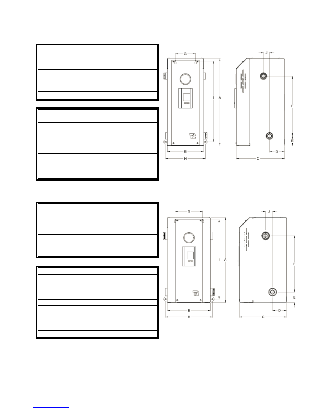
Table 2 : Boiler connections and dimensions (12-24 KW)
Connections
Inlet (return)
1 “ NPT Fem
Outlet (supply)
1 “ NPT Fem
Safety valve
1“reduced to 3/4 “ NPT Fem
Draining valve
1“reduced to 3/4 “ NPT Fem
Shipping weight
63 lbs
Item
Dimension (inches)
A
21-1/2 B 9 C 11-3/4
D
3-5/8
E
2-3/8
F
14-3/4 G 5 H 9-3/4
I
20 J 1-1/2
Connections
Inlet (return)
1 ¼ “ NPT Fem
Outlet (supply)
1 ¼ “ NPT Fem
Pressure relief valve
1 ¼“reduced to 3/4 NPTFem
Drain valve
1 ¼“reduced to 3/4NPT Fem
Shipping weight
75 lbs
Item
Dimension (inches)
A
21-1/2
B
11
C
11-3/4
D
3-1/2
E
2-3/4
F
14-1/4 G 7 H 11-5/8
I
20 J 1-3/4
Figure 1 : Boiler dimensions (12-24 KW)
Figure 2 : Boiler dimensions (27-36 KW)
Table 3 : Boiler connections and dimensions (27-36 KW)
BTH ULTRA Electric Boilers Installation & Operation manual (Revision: June 2015) 5

General Safety Precautions
List of components shipped with the unit :
Pressure relief valve set at 30 PSI.
Drain valve.
Two reducer fittings
Temperature & pressure indicator
Outdoor temperature sensor
Installation and operating manual
!
WARNING
!
Be sure to read and understand the entire Installation & operation manual before attempting to
install or to operate this water heater. Pay particular attention to the following General Safety
Precautions. Failure to follow these warnings could cause property damage, bodily injury or
death. Should you have any problems understanding the instructions in this manual, STOP,
and get help from a qualified installer or technician
Section 2: INTRODUCTION
These important safeguards and instruction appearing in this manual are not meant to cover all
possible conditions and situations that may occur. It should be understood that common sense,
caution and care are factors which cannot be built into every product. These factors must be
supplied by the person(s) caring for and operating the unit.
2.1 LOCAL INSTALLATION
REGULATIONS
This electric boiler must be installed in
accordance with these instructions and in
conformity with local codes, or in the absence of
local codes, with the National Plumbing Code
and the National Electric Code, current edition.
In any case where instructions in this manual
differ from local or national codes, the local or
national codes take precedence
2.2 CORROSIVE ENVIRONMENT
The electric boiler must not be installed near an
air duct supplying corrosive atmosphere or with
high humidity content.
When a boiler defect is caused by such
conditions, the warranty will not apply
2.3 INSPECTION UPON RECEPTION
Inspect the electric boiler for possible shipping
damage. The manufacturer’s responsibility
ceases upon delivery of goods to the carrier in
good condition. Consignee must file any claims
for damage, shortage in shipments, or nondelivery immediately against carrier.
2.4 TO BE CHECKED
Please check the identification tag on the unit to
make sure you have the right model (Capacity in
kilowatt, voltage, number of phase and ASME
construction or not ASME).
BTH ULTRA Electric Boilers Installation & Operation manual (Revision: June 2015) 6
Section 3: INSTALLATION
Sides
3 inches
Electric elements side
14 inches
Front side of the boiler
3 inches*
Back
0 inches
CAUTION
!
The manufacturer’s warranty does not cover any damage or defect caused by installation, or
attachment, or use of any special attachment other than those authorized by the manufacturer
into, onto, or in conjunction with the water heater. The use of such unauthorized devices may
shorten the life of the boiler and may endanger life and property. The manufacturer disclaims any
responsibility for such loss or injury resulting from the use of such unauthorized devices
3.1 SAFETY MEASURES
All installation will include the supplied pressure
relief valve which limits the maximum operating
pressure to 30 psi (207 kPa).
This electric boiler is designed to be installed on
a circuit operated between 50°F to 190°F (10°C
to 90°C) and at a maximum operating pressure
of 30 psi (207 kPa).
The unit in designed solely to be used on a
close loop hydronic heating system. The heat
transfer solution must be a solution of water or if
a freeze protection is required, a mix solution
Water/propylene glycol specially made for
hydronic heating systems and having a
maximum concentration of 50% (do not use
plumbing or automobile glycol).
The boiler is equipped with an automatic high
limit temperature control set at 210°F 99°C) and
some models have a second limit device
manually re-settable set at 227F (108C). If the
heating distribution system on which the boiler is
installed requires a high limit controller having a
lower setting, this controller will be added to the
system and connected in series with the factory
installed limit control.
3.2 LOCATION
The electric boiler should be installed in a clean,
dry location. Long hot water lines should be
insulated to conserve water and energy. The
electric boiler and water lines should be
protected from exposure to freezing
temperature.
The boiler can be mounted vertically or
horizontally directly on a solid surface with 4
adequate screws inserted in the provided boiler
openings. Make sure it is properly leveled
The electric boiler must be located or protected
so as not to be subject to physical damage, for
example, by moving vehicles, area flooding, etc.
All models can be installed directly on a
combustible wall and into an alcove. The
location must have sufficient ventilation to
maintain an ambient temperature not exceeding
90°F (32°C).
The electric boiler should not be located in
an area where leakage of the tank or water
connections will result in damage to the
adjacent area or to lower floors of the
structure. When such areas cannot be
avoided, a suitable drain pan or nonflammable catch pan, adequately drained
must be installed under the boiler.
The pan must be connected to a drain.
NOTE: Auxiliary catch pan MUST conform to
local codes.
3.3 CLEARANCES
For adequate inspection and servicing the
following minimum clearance is necessary:
Table 4: Boiler Clearances
*If the boiler is installed in a closed
compartment, allow an access service opening
and adequate ventilation to maintain an ambient
temperature lower than 90°F/32°C.
BTH ULTRA Electric Boilers Installation & Operation manual (Revision: June 2015) 7
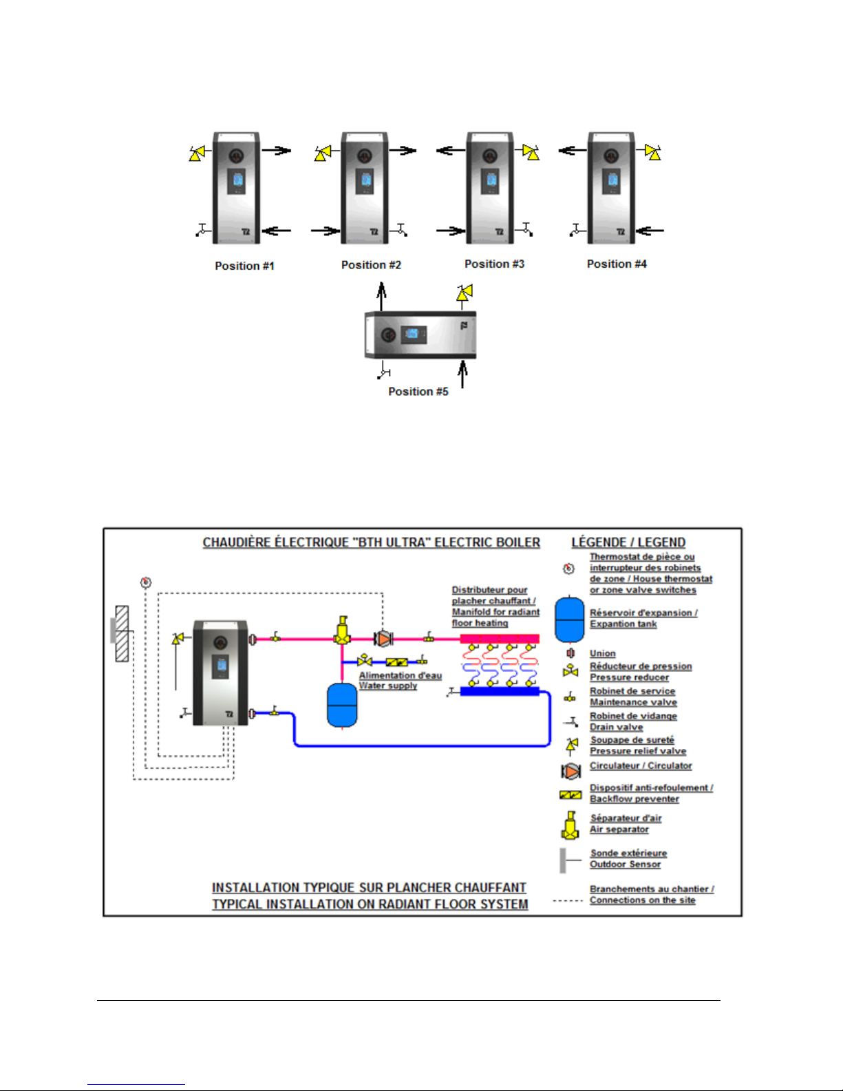
3.4 PIPING INSTALLATION
The inlet and outlet piping of the boiler must be in conformity with the different configurations shown
below. Make sure that the fluid flows is in the proper direction.
Figure 3 : Mounting positions
3.4.1 Type of installation
You will find below on figures 4 to 8 the typical piping arrangement for the two main types of installation.
The first being as a self-operating unit and the others being connected to an auxiliary boiler in dualenergy.
Figure 4 : Typical Installation on heating floor
BTH ULTRA Electric Boilers Installation & Operation manual (Revision: June 2015) 8
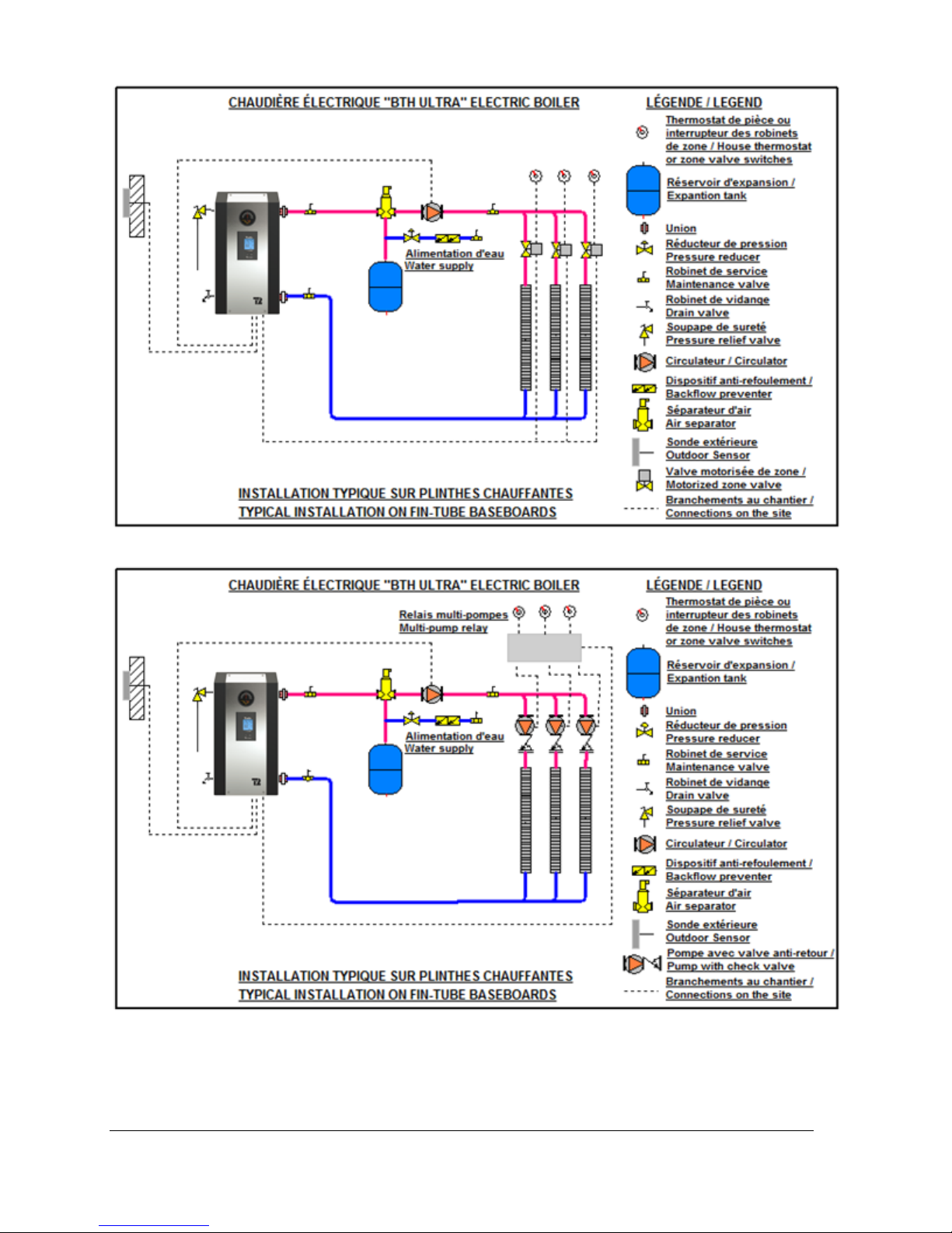
Figure 5 : Typical installation on fin-tube baseboards with zoning valves
BTH ULTRA Electric Boilers Installation & Operation manual (Revision: June 2015) 9
Figure 6 : Multi-pump zoning
 Loading...