

THERMO 2000 BTH 8, BTH 12, BTH 10, BTH 18, BTH 15 Use & Care Manual
...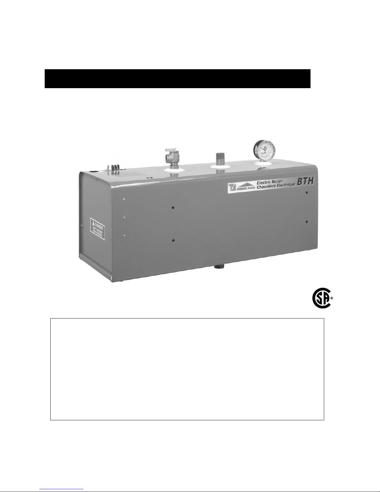
BTH Electric Boilers
Models ranging from 8 kW to 36 kW :
240 Volts ( 1 phase ) & 600 Volts ( 3 phases ).
USE & CARE MANUAL
WITH INSTALLATION INSTRUCTIONS FOR THE CONTRACTOR
Your BTH Electric Boiler has been carefully assembled and factory tested to provide years
of trouble-free service. The following information and safety measures are provided to
enable proper installation, operation, and maintenance of this product.
It is imperative that all persons who are expected to install, operate or adjust this boiler
should read these instructions carefully.
Any questions regarding the operation, maintenance, service or warranty of this electric
boiler should be directed to the supplier.
When all installation steps have been completed, insert this installation manual in its original
envelope, and keep in a safe place (close to the boiler) for future reference.
THERMO 2000 INCORPORATED revision:August/06
Printed in Canada

Ratings & Specifications
Electric Ratings for 240 VAC (1 phase) Electric Boilers:
Model
No.
BTH 8 5 000 3 000 ------ ------ 8 000 33.3 27 296 8 6 50 50 41.3
BTH 10 5 000 5 000 ------ ------ 10 000 41.6 34 120 6 6 60 60 52
BTH 12 3 000 3 000 3 000 3 000 12 000 50 40 944 6 4 70 70 62.5
BTH 15 3 000 4 500 3000 4 500 15 000 62.5 51 180 4 3 100 80 78.2
BTH 18 4 500 4 500 4500 4 500 18 000 75 61 416 3 2 100 100 93.8
BTH 20 5 000 5 000 5000 5 000 20 000 83.4 68 240 3 1 125 110 104
BTH 24 6 000 6 000 6000 6 000 24 000 100 81 888 1 0 125 125 125
BTH 27 3 x 4 500 3 x 4 500 27 000 112.5 92 124 1 0 150 150 140
BTH 30 3 x 5 000 3 x 5 000 30 000 125 102 360 2/0 3/0 200 175 156
BTH 33 3 x 5 000 3 x 6 000 33 000 138 112 596 2/0 3/0 200 200 172
Electric Elements
(in Watts)
A B C D Watts Amp. BTU CU AL Amp. Amp. Amp.
Total Wires Breakers Fuse
Electric Ratings for 600 VAC (3 phases) Electric Boilers:
Model
No. Quantity Watts Quantity Watts kW Amp. BTU RW-90 HRC “D”
BTH 9 3 3 000 ------- ------ 9 8.7 30 708 14 15 A
BTH 13 3 4 500 ------- ------ 13.5 13 46 062 12 20 A
BTH 18 6 3 000 ------- ------- 18 17 61 416 10 30 A
BTH 22 3 3 000 3 4 500 22.5 22 76 770 10 30 A
BTH 27 6 4 500 ------- ------- 27 26 92 124 8 40 A
BTH 30 6 5 000 ------- ------- 30 29 102 360 8 40 A
BTH 36 6 6 000 ------- ------- 36 35 122 832 8 50 A
Electric Elements Electric Elements Total Wires Fuse
Note: 1 kW =3,412Btu
Connections sizes & overall dimensions
125%
Connections sizes Boiler overall dimensions
Boiler return 1 “ NPT M Height 12 inches
Boiler feed 1 “ NPT M Width 12 inches
Waterworks 1/2 “ NPT F Depth 34 inches
Safety valve 3/4 “ NPT F Shipping weight 99 lbs.
Drain valve 1/2 “ NPT F
Drain valve
(BTH 33,36)
3/4 “ NPT M
Operating temperature : from 50°F to 190°F. Maximum operating pressure: 30 p.s.i.
BTH Electric Boilers USE & CARE MANUAL (Revision August /06), Page 2.
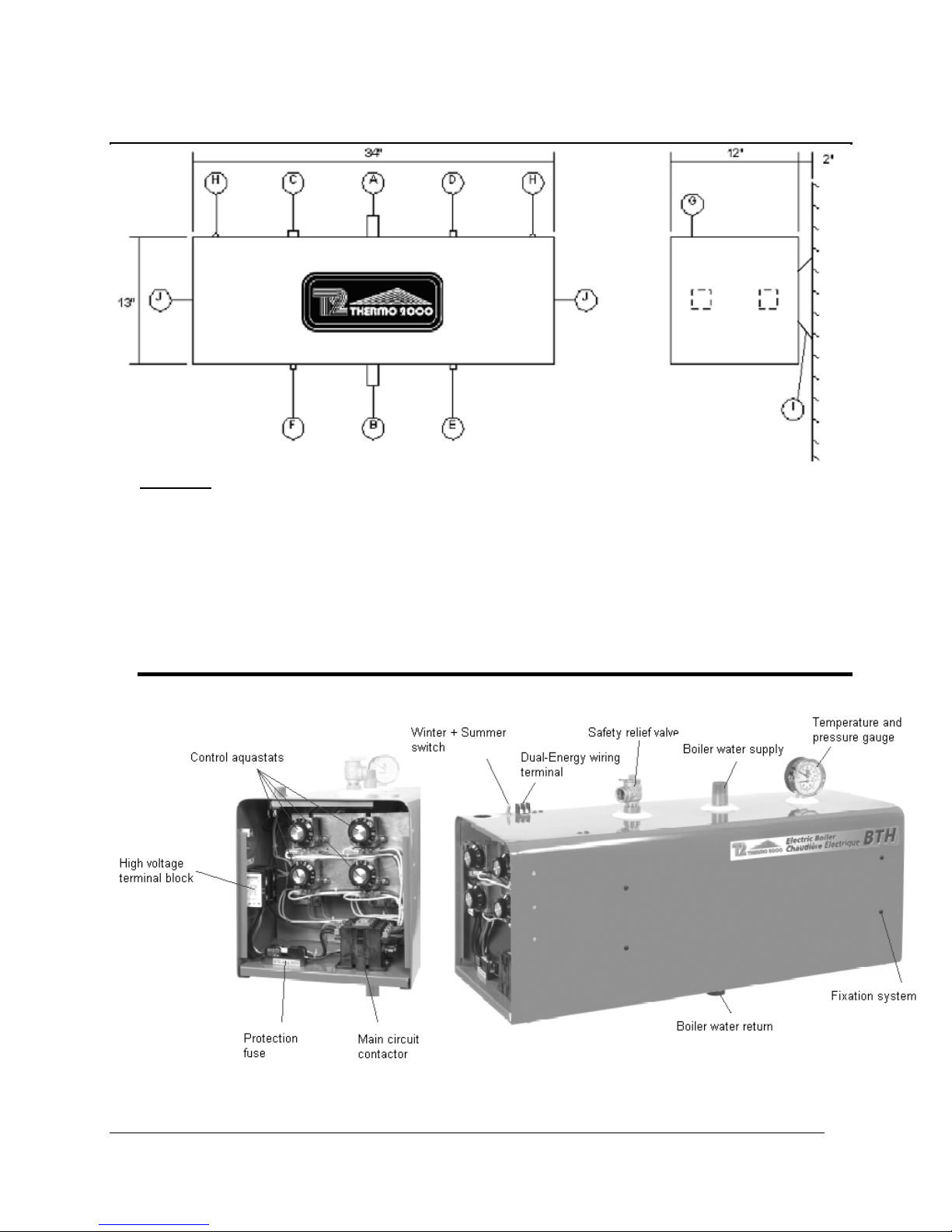
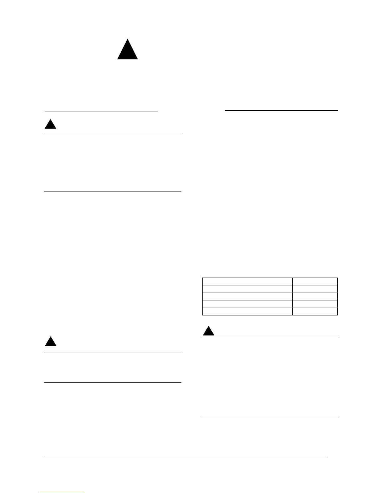
Unit description:
Legend :
A. Boiler Water Supply Connection ( 1 inch diameter, NPT male)
B. Boiler Water Return Connection ( 1 inch diameter, NPT male)
C. Safety Relief Valve ( ¾ inch NPT female )
D. Temperature & Pressure Gage (1/2 inch NPT female )
E. Drain Valve (1/2 inch NPT female )
F. Fill Water Connection (1/2 inch NPT female )
G. Electric Line Knock-Out ( 1 inch )
H. Pilot Light
I. Boiler Wall Hanging Brackets
J. Electrical Compartment
BTH Electric Boilers USE & CARE MANUAL (Revision August /06), Page 3.
General Safety Precautions
!
Be sure to read and understand the entire Use & Care Manual before attempting to install or to
operate this water heater. Pay particular attention to the following General Safety Precautions.
Failure to follow these warnings could cause property damage, bodily injury or death. Should
you have any problems understanding the instructions in this manual, STOP, and get help from
a qualified installer or technician.
Introduction
WARNING
!
These important safeguards and instruction
appearing in this manual are not meant to
cover all possible conditions and situations
that may occur. It should be understood that
common sense, caution and care are factors
which cannot be built into every product.
These factors must be supplied by the
person(s) caring for and operating the unit.
LOCAL INSTALLATION REGULATIONS
This electric boiler must be installed in
accordance with these instructions and in
conformity with local codes, or in the absence of
local codes, with the National Plumbing Code
and the National Electric Code, current edition.
In any case where instructions in this manual
differ from local or national codes, the local or
national codes take precedence.
SECURITY CONSIDERATIONS
Domestic and commercial installations have a
maximum design operating pressure limited to
30 psi by a safety relief valve.
Boiler maximum operating temperature is 190°F
by design. This boiler is designed to be used
only in a hot water heating system.
CAUTION
!
The heat transfer medium must be water or
other non-toxic fluid having a toxicity rating
or class of 1, as listed in clinical Toxicology
of Commercial products, 5
th
edition
LOCATION
The electric boiler should be installed in a clean,
dry location. Long hot water lines should be
insulated to conserve water and energy. The
electric boiler and water lines should be
protected from exposure to freezing
temperature.
The electric boiler must be installed horizontally
directly on the wall. Use the hanging brackets
for leveling the unit The electric boiler must be
located or protected so as not to be subject to
physical damage, for example, by moving
vehicles, area flooding, etc. All models can be
installed on combustible floors and in alcoves.
Ambient temperature must not exceed 80°F.
CLEARANCE
For adequate inspection and servicing the
following minimum clearance is necessary:
Right side 2 inches
Left side 14 inches
Top & Bottom of the boiler 6 inches
Front side of the boiler 24 inches
Back side of the boiler 1 inch
CAUTION
!
The electric boiler should not be located in
an area where leakage of the tank or water
connections will result in damage to the
adjacent area or to lower floors of the
structure. When such areas cannot be
avoided, a suitable drain pan or nonflammable catch pan, adequately drained,
and must be installed under the boiler.
The pan must be connected to a drain.
NOTE: Auxiliary catch pan MUST conform to
local codes.
BTH Electric Boilers USE & CARE MANUAL (Revision August /06), Page 4.

CORROSIVE ATMOSPHERE
The electric boiler should not be located near an
air vent blowing a corrosive atmosphere or high
humidity. The limited warranty is void when the
failure of the electric boiler is due to a corrosive
atmosphere.
CHECK LIST
Please check the identification tag on the unit to
make sure you have the right model.
List of components shipped with the unit :
• Pressure relief valve set at 30 PSI.
• Drain valve.
• Tridicator (temperature & pressure
gage).
SHIPMENT INSPECTION
Inspect the electric boiler for possible shipping
damage. The manufacturer’s responsibility
ceases upon delivery of goods to the carrier in
good condition. Consignee must file any claims
for damage, shortage in shipments, or nondelivery immediately against carrier.
BTH Electric Boilers USE & CARE MANUAL (Revision August /06), Page 5.

Installation
The manufacturer’s warranty does not cover
any damage or defect caused by installation,
or attachment, or use of any special
attachment other than those authorized by the
manufacturer into, onto, or in conjunction with
the water heater. The use of such
unauthorized devices may shorten the life of
the boiler may endanger life and property. The
manufacturer disclaims any responsibility for
such loss or injury resulting from the use of
such unauthorized devices
WIRING
Wiring must conform to the National Electrical
Code and to state or local code requirements.
The electric boiler must be electrically grounded in
accordance with local codes, or, in the absence of
local codes, with the National Electrical Code.
240Vac models
Wiring must be from a 240 Volt (single phase, 60
Hz) circuit protected by a properly sized breaker.
Wire gage (3 wires, ground) must be properly
sized. Consult the boiler rating plate to select the
proper breaker and wire gage.
600Vac models
Line wiring must be from a 600 Volt ( 3 phase, 60
Hz) circuit protected by a properly sized breaker.
Wire gage (3 wires, ground) must be properly
sized. Consult the boiler rating plate to select the
proper breaker and wire gage.
Circulator zoning wiring
Components must be wired to ensure that only the
circulator corresponding to the zone calling for
heat is actuated.
Zone valve zoning wiring
Connect the low voltage thermostat to the zone
valve. Components must be wired to ensure that
only the zone valve corresponding to the zone
calling for heat is actuated and that the circulator
is powered on a demand from any zone. The
transformer used to power the zone valves must
be sized for the load represented by all zone
valves in the heating system.
WARNING
!
BOILER WATER CONNECTIONS
This electric boiler may be connected individually
or in parallel with other boilers. If two or more
boilers are connected, the “reverse-return piping”
method (whereby the boiler with the first return
inlet also has the last supply outlet and so forth
until the last return inlet corresponds to the first
supply outlet) should be used to connect the
boilers in parallel, to ensure an equal water flow
rate through each boiler.
The boiler water supply, located on the top side,
and the boiler water return, located on the bottom
side of the boiler are steel pipes (male NPT
threaded connection) where supply and return line
connections are to be made.
Installing a union is recommended on the boiler
water supply and return lines to facilitate boiler
disconnection for servicing.
Dielectric unions are required for protection of the
boiler and piping if dissimilar pipe material such as
galvanized steel and copper are present.
Use only clean, new piping for boiler water lines.
Local codes or regulations shall govern the exact
type of material to be used.
Insulate all pipes containing hot water, especially
in unheated areas.
Install shutoff (ball) valves for servicing
convenience. Thermometer(s) should be installed
on the boiler water supply and return lines.
Cap or plug unused connections on the boiler. Do
not cap the pressure relief valve on the boiler
since it will damage and shorten the life of the
boiler and may endanger life and property.
Flow check valve
If the heating system includes a single pump, then
to minimize flow by gravity and heat loss during
non-draw periods, a flow check valve must
installed.
be
Pressure relief valve
An automatic pressure relief valve must be
installed during boiler setup. The pressure rating
of the relief valve must not exceed 30 psi. The
safety relief valve must meet the requirements of
BTH Electric Boilers USE & CARE MANUAL (Revision August /06), Page 6.

the ASME Boiler and Pressure Vessel Code and
limit the maximum operating boiler pressure. It is
a safety device, not an operating control.
The BTU per hour rating of the relief valve must
equal or exceed the BTU per hour input of the
boiler(s) or heat source(s) as marked on the
boiler(s) rating plate.
Connect the outlet of the relief valve to a
discharge line with its lower tip at most 6” above a
floor drain, well clear of any live electrical parts.
The discharge line must pitch downward from the
valve to allow complete draining by gravity of the
relief valve and discharge line, and be of a
diameter no smaller than that of the valve outlet.
The tip of the discharge line should not be
threaded or concealed and should be protected
from freezing. No valve of any type, restriction or
reducer coupling should be installed on the
discharge line. Local codes shall govern the
installation of relief valves.
SYSTEM PRESSURE CONTROL
Expansion tank
Pressure control devices within the system ensure
that each component operates within minimum
and maximum allowable pressures and maintain
minimum pressure for all normal operating
temperatures. They also allow air bleeding,
prevent cavitation at the pump inlet and prevent
water from boiling within the system; all this is
accomplished with minimal addition of new water.
The increase in boiler water volume resulting from
higher temperature is stored in the expansion tank
during periods of high operating temperature and
is returned to the system when the temperature
decreases.
The expansion tank must be able to store the
required volume of boiler water during maximum
design operating temperature without exceeding
the maximum allowable operating pressure, and
to maintain the required minimum pressure when
the system is cold. Contact your installing
contractor, plumbing supply house, or local
plumbing inspector for assistance.
The point where the expansion tank is connected
should be carefully selected to avoid the
possibility that normal operation of automatic
check or manual valves will isolate the tank from a
hot boiler or any part of the system. Pre-charged
diaphragm expansion tanks are preferable to air
control.
These tanks incorporate a balloon-like bladder or
diaphragm. It is inflated, prior to filling the system,
to a pressure equal to the setting of the water
pressure makeup regulator.
The expansion tank should be located on the
suction or intake side of the pump. The pump can
be located either just upstream or just
downstream from the boiler.
BTH Electric Boilers USE & CARE MANUAL (Revision August /06), Page 7.

Water pressure makeup regulator
Make-up systems must be employed as required
by codes. An automatic fill valve must be used
with a backflow preventer as required, to maintain
minimum system pressure by supplying water to
make up for leakage.
Air bleeder
Oxygen should be excluded from the system to
prevent corrosion. As mentioned in the expansion
tank paragraph above, this precludes the use of
air in direct contact with the boiler water as a
pressurization means.
Installation of manual or automatic air vent
devices prevents air from accumulating in the
system. Air vents should be installed at all high
points to remove trapped air during initial setup
and to ensure that the system is tight. Regularly
purge the air out of the system while taking care to
avoid personal injuries or property damage
caused by hot boiler water spray.
Circulator zoning recommendations
The preferred location of the circulator pump for
each zone is on the boiler supply side, with the
expansion tank between the boiler and the pump.
A flow check valve must be installed in each zone,
preferably on the outlet side of each circulator
pump, to prevent water flow to other zones where
no heat is required.
Zone valve zoning recommendations
The preferred location of the circulator pump is on
the boiler supply side, with the expansion tank
between the boiler and the circulator. Use zone
valves with low pressure drop.
Dual energy installation
In order to obtain a special rate from your electric
utility for residential use, your BTH boiler can be
hooked-up to an existing oil heater. Contact your
electric utility to find out if your property is eligible
for such rates and how to register for them.
The CBE-EM dual-energy control (an available
option, three-way, motorized valve (1’’ NPT F
standard) included) is specially designed to
electric utility standards. The CBE-EM control
selects the least expensive energy source based
on outside temperature, user choice or a signal
from your utility.
The CBE-EM dual-energy control will start up the
oil burner upon receiving the appropriate signal,
even if the thermostat in the house is not calling
for heat. It will shut off when the temperature in
the boiler reaches its target on the Limit Control. It
is for this reason that the piping requires an antigravity valve (flow check valve) or motorized zone
valves.
A three-way, motorized valve (1’’ NPT F standard)
will direct the water flow either to the oil-fired
heater or to your DTH electric boiler, depending
on the signal received. This way, your oil heater
will cool down and eliminate any energy loss,
either through the chimney or by way of
conduction in the boiler room.
BTH Electric Boilers USE & CARE MANUAL (Revision August /06), Page 8.
 Loading...