

Page 1

OPERATING AND SERVICE MANUAL
AC-4000 CONTROLLER
WAREHOUSE APPLICATION
REC 3838 REV G 10/05
PART NO. 045848
Page 2

REVISION HISTORY
REVISION A DECEMBER 1993
REVISION B APRIL 1994
REVISION C AUGUST 1995
REVISION D NOVEMBER 1995
REVISION E APRIL 1999
REVISION F SEPTEMBER 2000
REVISION G OCTOBER 2005
COPYRIGHT 1993, 1994, 1995, 1999 BY THERMO ELECTRON, INC
THIS DOCUMENT IS CONFIDENTIAL AND IS THE PROPERTY OF THERMO ELECTRON IT
MAY NOT BE COPIED OR REPRODUCED IN ANY WAY WITHOUT THE EXPRESS WRITTEN
CONSENT OF THERMO. THIS DOCUMENT ALSO IS AN UNPUBLISHED WORK OF THERMO.
THERMO INTENDS TO AND IS MAINTAINING THE WORK AS CONFIDENTIAL INFORMATION.
THERMO ALSO MAY SEEK TO PROTECT THIS WORK AS AN UNPUBLISHED COPYRIGHT.
IN THE EVENT OF EITHER INADVERTENT OR DELIBERATE PUBLICATION, THERMO
INTENDS TO ENFORCE ITS RIGHTS TO THIS WORK UNDER THE COPYRIGHT LAWS AS A
PUBLISHED WORK. THOSE HAVING ACCESS TO THIS WORK MAY NOT COPY, USE OR
DISCLOSE THE INFORMATION IN THIS WORK UNLESS EXPRESSLY AUTHORIZED BY
THERMO.
PLEASE READ AND OBSERVE THE FOLLOWING SAFETY
PRECAUTIONS FOUND THROUGHOUT THIS MANUAL.
DANGER
FAILURE TO OBSERVE WILL CAUSE VERY SERIOUS PERSONAL INJURY OR DEATH.
WARNING
FAILURE TO OBSERVE COULD CAUSE SERIOUS PERSONAL INJURY.
CAUTION
FAILURE TO OBSERVE MAY CAUSE MINOR OR MODERATE PERSONAL INJURY
OR DAMAGE TO THE EQUIPMENT.
REC 3838 II
Page 3

ICORE PRODUCTS
AC-4000 ELECTRONICS
TABLE OF CONTENTS
CHAPTER TITLE PAGE
1.0 INTRODUCTION ................................................. 1-1
1.1 GENERAL DESCRIPTION ................................ 1-1
1.1.1 Applications ....................................1-1
1.1.2 System Description ..............................1-1
1.1.3 Operation......................................1-1
1 . 1 . 4 F e a ture s ......................................1-3
1.2 OPTIONS ............................................. 1-3
1.2.1 15 Programmable Product Set-Ups . . . . . . . . . . . . . . . . . . 1-3
1.2.2 Communications (COM) ..........................1-3
1.3 WARRANTY .................. .. ....................... 1-6
2 . 0 I N S T ALLATI O N .................................................. 2-1
2.1 GENERAL ............................................. 2-1
2.2 SAFETY PRECAUTIONS ................................. 2-1
2.2.1 Occupational Safety and Health Act (OSHA) . . . . . . . . . . . 2-2
2.3 STORAGE............................................. 2-2
2.4 UNCRATING & INSPECTION .............................. 2-2
2.5 EQUIPMENT LOCATION ................................. 2-3
2.6 INSTALLATION .......................... ............... 2-4
2.6.1 Initial Power On .................................2-4
3.0 OPERATION .............. ...................................... 3-1
4 . 0 M A I N T E NA NCE.................................................. 4-1
4.1 GENERAL ............................................. 4-1
4.2 SERVICE & REPAIR ..................................... 4-1
4.3 COMPONENT REPLACEMENT PROCEDURES (ELECTRICAL) . . . 4-1
4.3.1 Display Board Assembly Replacement . . . . . . . . . . . . . . . 4-1
4.3.2 Display Module Replacement . . . . . . . . . . . . . . . . . . . . . . 4-2
REC 3838 III
Page 4

TABLE OF CONTENTS
(continued)
CHAPTER TITLE PAGE
4.3.3 Communications Board Replacement . . . . . . . . . . . . . . . . 4-4
4.3.4 CPU Board Replacement..........................4-4
4.3.5 Analog Board Replacement . . . . . . . . . . . . . . . . . . . . . . . . 4-4
4.3.6 Distribution Board Replacement . . . . . . . . . . . . . . . . . . . . 4-7
4.3.7 Front Panel Replacement . . . . . . . . . . . . . . . . . . . . . . . . . 4-9
4.3.8 Motor Speed Control Module Replacement . . . . . . . . . . . 4-11
4.3.9 Cold Start Procedure ............................4-11
4.4 TROUBLESHOOTING .................................. 4-13
5.0 REPLACEMENT PARTS ........................................... 5-1
5.1 GENERAL .......................... ................... 5-1
5.2 ORDER INFORMATION .................................. 5-1
5.3 PARTS LIST INDEX ..................................... 5-2
5.3.1 Return Material Authorization . . . . . . . . . . . . . . . . . . . . . . . 5-3
6.0 AC-4000 OPTIONS ............................................... 6-1
6.1 VARIABLE SPEED ...................................... 6-1
6.1.1 Installation ........................ .............6-1
6.2 COMMUNICATIONS .................................... 6-2
6.2.1 Installation .....................................6-2
6.2.2 External Communication Cabling . . . . . . . . . . . . . . . . . . . . 6-4
6.2.3 Interconnect Information . . . . . . . . . . . . . . . . . . . . . . . . . . 6-6
6.3 MULTIPLE PRODUCT.................................... 6-7
6.3.1 Installation ........................ .............6-7
6.4 MOTOR INHIBIT ........................................ 6-8
REC 3838 IV
Page 5

LIST OF ILLUSTRATIONS
FIGURE NO. TITLE PAGE
1-1 AC-4000 Electronics ............................................. 1-0
1-2 System Block Diagram ........................................... 1-2
2-1 Input Power Connections.......................................... 2-4
2-2 Analog Board................................................... 2-5
2-3 Distribution Board ............................................... 2-6
4-1 Display Board Assembly/Module Replacement . . . . . . . . . . . . . . . . . . . . . . . . . 4-3
4-2 Communications, CPU and Analog Board Replacement . . . . . . . . . . . . . . . . . . 4-6
4-3 Distribution Board Replacement .................................... 4-8
4-4 Distribution Board with Options ..................................... 4-8
4-5 Front Panel Replacement ......................................... 4-10
6-1 Communications Board Dip Switches . . . . . . . . . . . . . . . . . . . . . . . . . . . . . . . . 6-3
6-2 RS-232 Connections ............................................. 6-4
6-3 RS-485 Connections ............................................. 6-5
LIST OF TABLES
TABLE NO. TITLE PAGE
1-1 Technical Specifications .......................................... 1-4
4-1 Troubleshooting Procedures ....................................... 4-13
4-2 Power Troubleshooting Procedure................................... 4-18
5-1 AC-4000 Electronics (Remote or Local) . . . . . . . . . . . . . . . . . . . . . . . . . . . . . . . 5-4
6-1 Variable Speed Option............................................ 6-1
6-2 Communications Option .......................................... 6-3
6-3 Interconnect Terminations ......................................... 6-6
6-4 Multiple Project Option............................................ 6-7
REC 3838 V
Page 6

APPENDIX
NO. TITLE DRAWING NO.
A/1 Field Wiring Diagram .................................. Engineer
Selected
A/2 Interconnect Wiring Diagram ............................ D07226K-E079
A/3 CPU Board Schematic................................. D07226K-E004
A/4 Analog Board Schematic ............................... D07226K-E014
A/5 Display Board Schematic ............................... D07226K-E024
A/6 Communications Board Schematic . . . . . . . . . . . . . . . . . . . . . . . D07226K-E034
A/7 Distribution Board Schematic............................ C07226K-E054
SUPPLEMENTAL MANUALS
TITLE DOCUMENT NO.
Minarik Adjustable Speed Control, Model MM 2300 . . . . . . . . . . . MC-3
REC 3838 VI
Page 7

PREFACE
This manual contains information necessary to install, operate, and service the Thermo AC4000 Electronics (see Figure 1-1).
All persons concerned with the operation and servicing of the electronics should read the
contents of this manual carefully and thoroughly. Keep this manual in a convenient place and
refer to it often, as it is an important tool in performing proper service.
Information in this manual is presented as follows:
Chapter 1.0, INTRODUCTION, presents a brief description of the electronics' capabilities,
operation, features, options specifications and warranty.
Chapter 2.0, INSTALLATION, outlines site preparation operating requirements, and installation
instructions.
Chapter 3.0, OPERATION, explains the operating controls and procedures.
Chapter 4.0, MAINTENANCE, includes troubleshooting, electronic checkout, and maintenance
procedures.
Chapter 5.0, REPLACEMENT PARTS, provides ordering information and replaceable parts list.
Chapter 6.0, OPTIONS, contains information about optional equipment.
The APPENDIX contains assembly, installation, and wiring drawings.
IMPORTANT
Do not turn the equipment on or attempt to operate the electronics until you have read and
understood Chapter's 2.0 and 3.0. Improper operation of the electronics may result in damage
to the machine.
REC 3838 VII
Page 8

REC 3838 1-0
AC-4000 ELECTRONICS
FIGURE 1-1
Page 9

CHAPTER 1.0
INTRODUCTION
1.1 GENERAL DESCRIPTION
The AC-4000 Electronics System is a high accuracy machine. When combined with a
weighing frame, it performs weight inspection of individual product packages in a
production process or package line. The AC-4000 and a weighing frame perform these
functions without interrupting product flow.
1.1.1 Applications
Typical applications for the AC-4000 Electronics System are the in-motion
weighing of:
Frozen food, bakery, confectionery, meat, and any canned or packaged goods.
Detergents, chemicals, pharmaceutical, and any bottled liquid products.
Manufactured products such as rubber, plastic, metal parts, multi-component parts
packages, and count-by-weight packages.
1.1.2 System Description
The AC-4000 Electronics System consists of:
A microprocessor-based electronic system with filtering and amplification circuitry
to interpret the signal from a loadcell. The electronics enclosure houses the CPU,
A/D and display boards.
A front panel keypad and vacuum fluorescent display. The digital keypad is used
to enter set-up parameters. The display presents weight.
1.1.3 Operation
Upon installation, certain data must be entered into the AC-4000 electronics. The
AC-4000's front panel is designed to simplify set-up and operation of a machine.
All data is entered digitally, using the keyboard buttons on the front panel. The
operator is assisted in set-up by the fluorescent displays that show what data to
enter.
During operation, the package is transported by a conveying medium (such as
chains or belts) across a weightable. The loadcell supporting a weightable
produces an electronic signal proportional to the package weight. As the package
interrupts a beam from a photocell sensor (interlock), the gross weight of the
package is computed by the AC-4000 electronics.
The AC-4000 displays the weight of the package in grams, kilograms, ounces or
pounds.
REC 3838 1-1
Page 10

REC 3838 1-2
SYSTEM BLOCK DIAGRAM
FIGURE 1-2
Page 11

1.1.4 Features
The AC-4000 Electronics System has the following standard features:
1. Auto Zero and Manual Zero
The electronics automatically compensate for minor buildup on the weightable
by rezeroing the weightable between packages. Manual zero allows the
rezeroing of the weightable at the operator's discretion.
2. Automatic Self-Diagnostics
This feature continually monitors system operation and assures that
everything is operating properly.
3. Digital Filter
During set-up, filter parameters are selected for individual products using the
front panel keyboard. This exclusive feature improves the weighing accuracy
by providing the best filter setting for each product.
4. Password Protection
This feature provides protection against an unauthorized change in set-up
parameters and access to certain data.
5. Permanent Data Storage
An EEPROM retains set-up information and stores accumulated data.
6. 32-Bit Microprocessor
This large memory capacity increases the flexibility of the AC-4000 and allows
it to handle a broader range of applications.
7. Corrosion Resistant Finish
All exposed metal parts on the AC-4000 Electronics System are either
stainless steel or painted mild steel.
8. 20 bit analog to digital converter (A/D) for loadcell signal.
1.2 OPTIONS
Electronics can be remote or local, and numerous options are available to transform the
AC-4000 from a low-cost, basic electronics into a sophisticated tool for monitoring
productivity and packaging line performance. These options include the following:
1.2.1 15 Programmable Product Set-Ups
The set-up parameters for 15 products can be preset into the electronics. The
AC-4000 can then be switched from one product to another in a matter of
seconds.
1.2.2 Communications (COM)
Provides for communication of weight or statistical information from the AC-4000
to a printer, CRT, or host computer.
REC 3838 1-3
Page 12

TABLE 1-1
TECHNICAL SPECIFICATIONS - AC-4000 ELECTRONICS
Package Rate To 350 PPM
Accuracy:
Displayed Resolution ±1, ±0.1, or ±0.01 Units
Zeroing Automatic self zeroing between packages.
REZERO light turns on if an autozero cannot occur
within two minutes.
Environment:
Electrostatic Discharge
Temperature
Humidity
5000 V
14° to 122°F (-10° to +50°C)
0% to 95%
Electrical:
Standard
100-130/200-250 VAC, 50/60 Hz, 300 VA
Neutral to Ground
Maximum Voltage
140 Volt AC
REC 3838 1-4
Page 13

TABLE 1-1
TECHNICAL SPECIFICATIONS - (Continued)
REC 3838 1-5
Page 14

1.3 WARRANTY
Thermo Electron
WARRANTY
The seller agrees, represents, and warrants that the equipment delivered hereunder shall be free
from defects in material and workmanship. Such warranty shall not apply to accessories, parts,
or material purchased by the seller unless they are manufactured pursuant to seller's design, but
shall apply to the workmanship incorporated in the installation of such items in the complete
equipment. To the extent purchased parts or accessories are covered by the manufacturer's
warranty, seller shall extend such warranty to buyer.
Seller's obligation under said warranty is conditioned upon the return of the defective equipment,
transportation charges prepaid, to the seller's factory in Minneapolis, Minnesota, and the
submission of reasonable proof to seller prior to return of the equipment that the defect is due to
a matter embraced within seller's warranty hereunder. Any such defect in material and
workmanship shall be presented to seller as soon as such alleged errors or defects are discovered
by purchaser and seller is given opportunity to investigate and correct alleged errors or defects and
in all cases, buyer must have notified seller thereof within one (1) year after delivery, or one (1)
year after installation if the installation was accomplished by the seller.
Said warranty shall not apply if the equipment shall not have been operated and maintained in
accordance with seller's written instructions applicable to such equipment, or if such equipment
shall have been repaired or altered or modified without seller's approval; provided, however, that
the foregoing limitation of warranty insofar as it relates to repairs, alterations, or modifications, shall
not be applicable to routine preventive and corrective maintenance which normally occur in the
operation of the equipment.
"EXCEPT FOR THOSE WARRANTIES SPECIFICALLY CONTAINED HEREIN, SELLER
DISCLAIMS ANY AND ALL WARRANTIES WITH RESPECT TO THE EQUIPMENT DELIVERED
HEREUNDER, INCLUDING THE IMPLIED WARRANTIES OF MERCHANTABILITY AND
FITNESS FOR USE. THE SOLE LIABILITY OF SELLER ARISING OUT OF THE WARRANTY
CONTAINED HEREIN SHALL BE EXCLUSIVELY LIMITED TO BREACH OF THOSE
WARRANTIES. THE SOLE AND EXCLUSIVE REMEDY FOR BREACH OF THE WARRANTIES
SET OUT ABOVE SHALL BE LIMITED TO THE REPAIR OR REPLACEMENT OF ANY
DEFECTIVE ACCESSORY, PART OR MATERIAL WITH A SIMILAR ITEM FREE FROM DEFECT,
AND THE CORRECTION OF ANY DEFECT IN WORKMANSHIP. IN NO EVENT SHALL SELLER
BE LIABLE FOR ANY INCIDENTAL OR CONSEQUENTIAL DAMAGES."
FIELD SERVICE
Purchaser agrees to underwrite the cost of any labor required for replacement; including time,
travel, and living expenses of Thermo Field Service Engineer at closest factory base.
Thermo Electron
501 90th Avenue N.W.
Minneapolis, MN 55433
Phone: (612) 783-2500
Fax: (612) 783-2525
REC 3838 1-6
Page 15

CHAPTER 2.0
INSTALLATION
2.1 GENERAL
The customer is responsible for initial inspection of the equipment and site preparation. It
is essential that the equipment be placed on the production line in accordance with the
guidelines set forth in this section. The customer must ensure that qualified personnel are
available to make interconnections with other production equipment and perform work at
the installation site. An Thermo Products Customer Service representative is available to
supervise installation and verify operation as well as train personnel assigned to operate
and maintain the equipment.
2.2 SAFETY PRECAUTIONS
IMPORTANT
Do not install, operate, or perform any maintenance procedures until you have read the
safety precautions presented below.
1. Do not connect power to the machine or turn on the unit until you have read and
understood this entire manual. The precautions and procedures presented in this
manual must be followed carefully in order to prevent equipment damage and
protect the operator from possible injury.
2. CAUTION! Hands and clothing must be kept away from all moving or rotating
parts.
3. WARNING! Covers over the electronics, or rotating parts should always remain in
place during operation. They should be removed only for maintenance procedures
with the machine's power OFF. Be sure to replace all covers before resuming
operation.
4. WARNING! All switches (control, motor, power, etc., as applicable) must be OFF
when checking input AC electrical connections, removing or inserting printed circuit
boards, or attaching voltmeters to the system.
5. Incoming voltages must be checked with a voltmeter before being connected to the
machine. Pay special attention to the red tag attached to the machine that
stipulates the correct input voltage for your particular unit.
6. WARNING! Extreme caution must be used in testing in, on, or around the
electronics cabinet, PC boards, or modules. There are voltages in excess of 115 V,
230 V, or 440 V in these areas. Avoid high voltage and static electricity around the
printed circuit board.
7. CAUTION! Do not leave insulating material over the machine for any length of time
or the machine will overheat. The specified maximum ambient temperature is not to
be exceeded for more than 5 minutes.
8. Maintenance procedures should be performed only by qualified personnel and in
accordance with procedures/instructions given in this manual.
9. During maintenance, a safety tag (not supplied by Thermo) should be displayed in
the ON/OFF switch areas as a precaution instructing others not to operate the unit
(ANSI:B157.1).
REC 3838 2-1
Page 16

10. Only qualified electricians should be allowed to open and work in the electronics
cabinets, power supply cabinets, control cabinets, or switch boxes.
11. Objects of any kind should never be placed or stored on the machine.
12. This equipment should not be operated at more than the specified production rate
nor utilized in applications other than those stated in the original order. (To adapt
production rates or applications, consult Thermo Products Customer Service for
recommendations.)
13. All panels and doors covering the electronics must be in place and tight before
conducting washdown. Damage to the electronics could result from water,
moisture, or contamination in the electronics housing.
14. Harsh chemicals, caustics, disinfectants, etc., should never be added to washdown
solutions.
15. Infeed and outfeed conveyors and transfer assemblies should be mounted and/or
positioned so clearance is maintained between moving parts. Check to ensure
weighing or infeed/outfeed conveyor(s) are clear of debris before turning the drive
motor ON.
2.2.1 Occupational Safety and Health Act (OSHA)
The Occupational Safety and Health Act clearly places the burden of compliance
on the user of the equipment and the act is generalized to the extent that
determination of compliance is a judgement decision on the part of the local
inspection. Hence Thermo Electron will not be responsible for meeting the full
requirements of OSHA in respect to the equipment supplied or for any penalty
assessed for failure to meet the requirements, in respect to the equipment
supplied, of the Occupational Safety and Health Act, as interpreted by an
authorized inspector. Thermo Electron will use their best efforts to remedy such
violation at a reasonable cost to the buyer.
2.3 STORAGE
If you are not going to install the electronics system now, it can be safely stored at
temperatures from -40° F (-40° C) to +158° F (+70° C). All components should be
protected against moisture.
2.4 UNCRATING & INSPECTION
The electronics system has been properly packaged for shipment. Inspect all packages
for damage before opening as often times the carrier may be responsible for shipping
damage.
1. Inspect the electronics for shipping damage.
2. Remove the poly covering from the electronics.
3. Cut the nylon shipping bands securing the electronics to pallet.
4. Lift the electronics and pedestal off the pallet.
REC 3838 2-2
Page 17

2.5 EQUIPMENT LOCATION
Careful consideration should be given to the location of the electronics, as system
performance is affected by its location. The following requirements must be followed.
1. The electronics should be located so maintenance personnel can easily perform
cleaning and adjustment procedures, and so both the control panel and electronics
enclosure rear doors are easily accessible. This requires clear space behind and in
front of the machine.
2. There should be a minimum of vibration in the area. Vibrations can be conducted to
a loadcell and affect weighing accuracy.
3. The electronics system is designed to operate in an environment where the
temperature ranges no lower than -14° F (-10° C) nor higher than 122° F (50° C).
4. The electronics will operate in an environment where the humidity (non-condensing)
ranges from 0% to 95%.
REC 3838 2-3
Page 18
2.6 INSTALLATION
The procedures given below provide for installing the electronics in your production line.
2.6.1 Initial Power On
The initial power on procedures describe the checks to be performed before the
initial system setup procedures are performed.
1. Verify that the fuses on the Analog Board (Figure 2-2) and Distribution Board
(Figure 2-3) inside the controller enclosure are correct for the AC input
voltage. The following lists define the correct fuses.
REC 3838 2-4
INPUT POWER CONNECTIONS
FIGURE 2-1
Page 19

ANALOG BOARD
FUSE 115VAC 220VAC
F1 (for electronics) 3/8A, 3AG, SB 3/16A, 3AG, SB
F2 (for line [L2]) 10A, 3AB, SB 10A, 3AB, SB
REC 3838 2-5
ANALOG BOARD
FIGURE 2-2
Page 20

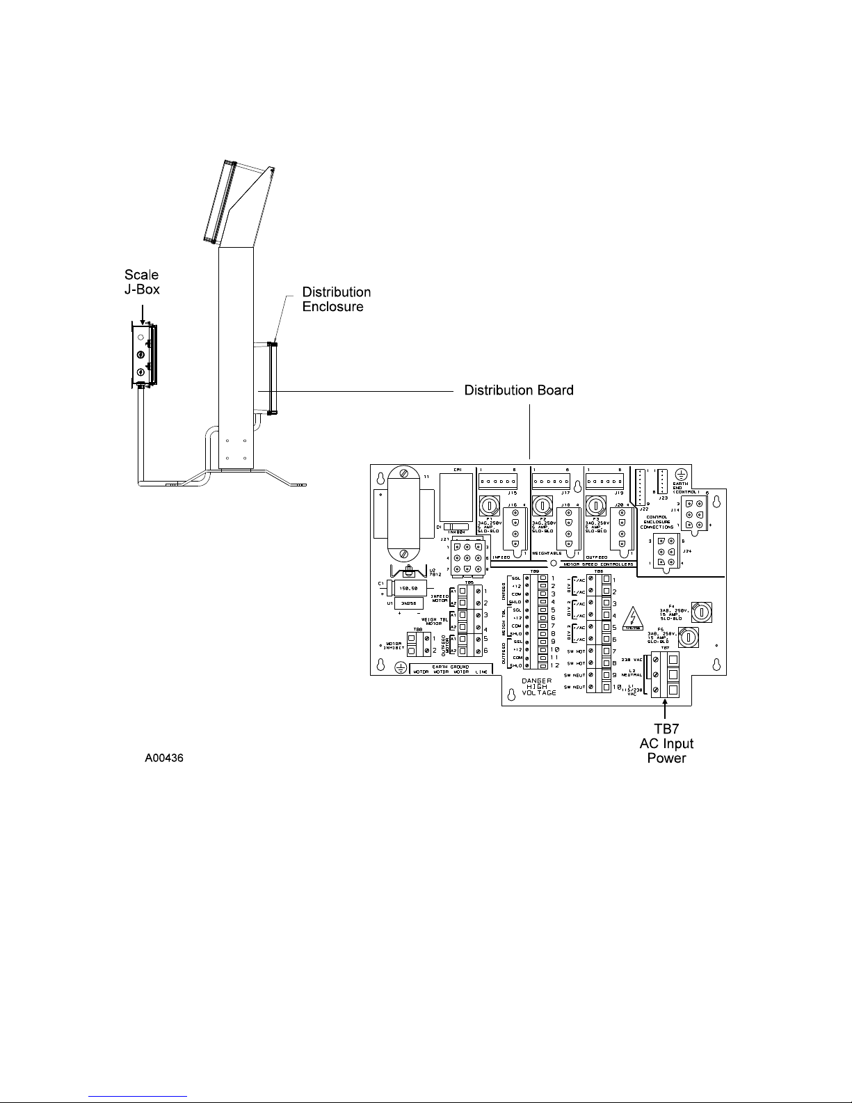
DISTRIBUTION BOARD
FUSE 115VAC/220VAC
F1 (for infeed motor) 5A, 3AG, SB
F2 (for weightable motor) 5A, 3AG, SB
F3 (for outfeed motor) 5A, 3AG, SB
F4 (for line [L1]) 15A, 3AB, SB
F5 (for line [L2]) 15A, 3AB, SB
REC 3838 2-6
DISTRIBUTION BOARD
FIGURE 2-3
Page 21

2. Verify that switch SW-2 on the Analog Board is set to the correct AC input
voltage.
3. Verify that the dip switches on the Analog Board are correct for your
configuration. The following list defines the standard switch settings for the
Analog Board, if the specific options noted are installed. (For options see
Chapter 6.0.)
ANALOG BOARD DIP SWITCHES
SWITCH POSITION DESCRIPTION
SW1-1 OFF/OPEN
ON/CLOSED*
SW1-2 OFF/OPEN
ON/CLOSED*
SW1-3 OFF/OPEN*
ON/CLOSED
SW1-8 ON/CLOSED*
OFF/OPEN
Reserved.
Switch must be in this position.
Standard weightable speed sensor.
No weightable speed sensor.
Optional infeed with speed sensor.
No infeed speed sensor.
Normal Run position.
Remove forgotten password.
Others OFF/OPEN Not Used
*Default position.
4. Turn the front panel CONVEYOR POWER switch ON and verify that the belt
(chains) are running.
5. Turn the ELECTRONICS POWER switch ON and let the electronics warm up.
REC 3838 2-7
Page 22

This page intentionally left blank
Page 23

Page 24

This page intentionally left blank
Page 25

Page 26

This page intentionally left blank
Page 27
Page 28

Page 29
Page 30
Page 31

Page 32

This page intentionally left blank
Page 33

Page 34

Page 35

Page 36

Page 37

Page 38

Page 39

Page 40

Page 41
Page 42

Page 43
Page 44

Page 45

Page 46

Page 47

Page 48

Page 49

Page 50

Page 51

Page 52

Page 53

Page 54

Page 55

Page 56

Page 57

Page 58

Page 59
Page 60

Page 61

Page 62
Page 63
Page 64

Page 65

Page 66
Page 67

Page 68

Page 69

Page 70

Page 71

Page 72

Page 73

Page 74

Page 75
Page 76

Page 77
Page 78
Page 79
Page 80

Page 81

Page 82

Page 83

Page 84

Page 85

Page 86

Page 87

Page 88

Page 89

Page 90
Page 91

Page 92

Page 93
Page 94
Page 95

Page 96

Page 97

Page 98

Page 99

Page 100

 Loading...