

Page 1
BioMate™ 3 Series
Spectrophotometers
Operator’s Manual
Page 2

Page 3
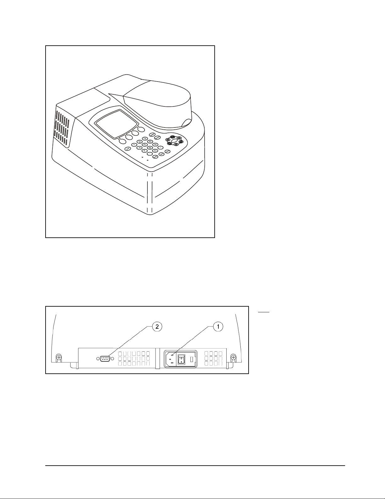
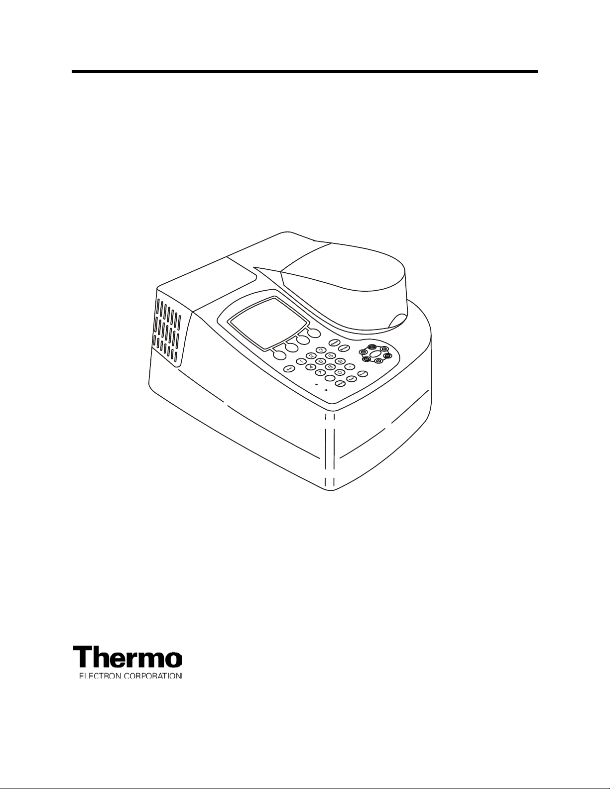
Figure 1 BioMate 3 spectrophotometer
Figure 2 Back panel of the spectrophotometer
Key/
c A/C power connector
d RS232C port
Page 4
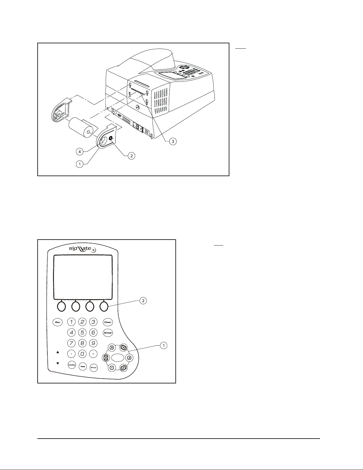
Figure 3 Installing the paper roll holders for the internal printer (335988)
Figure 4 Keypad of the BioMate 3 spectrophotometer
Key
c Cell position keys
d Function keys
Key/
c Paper roll holder
d Icon for paper direction
e Paper entry slot
f Finger tab
Page 5
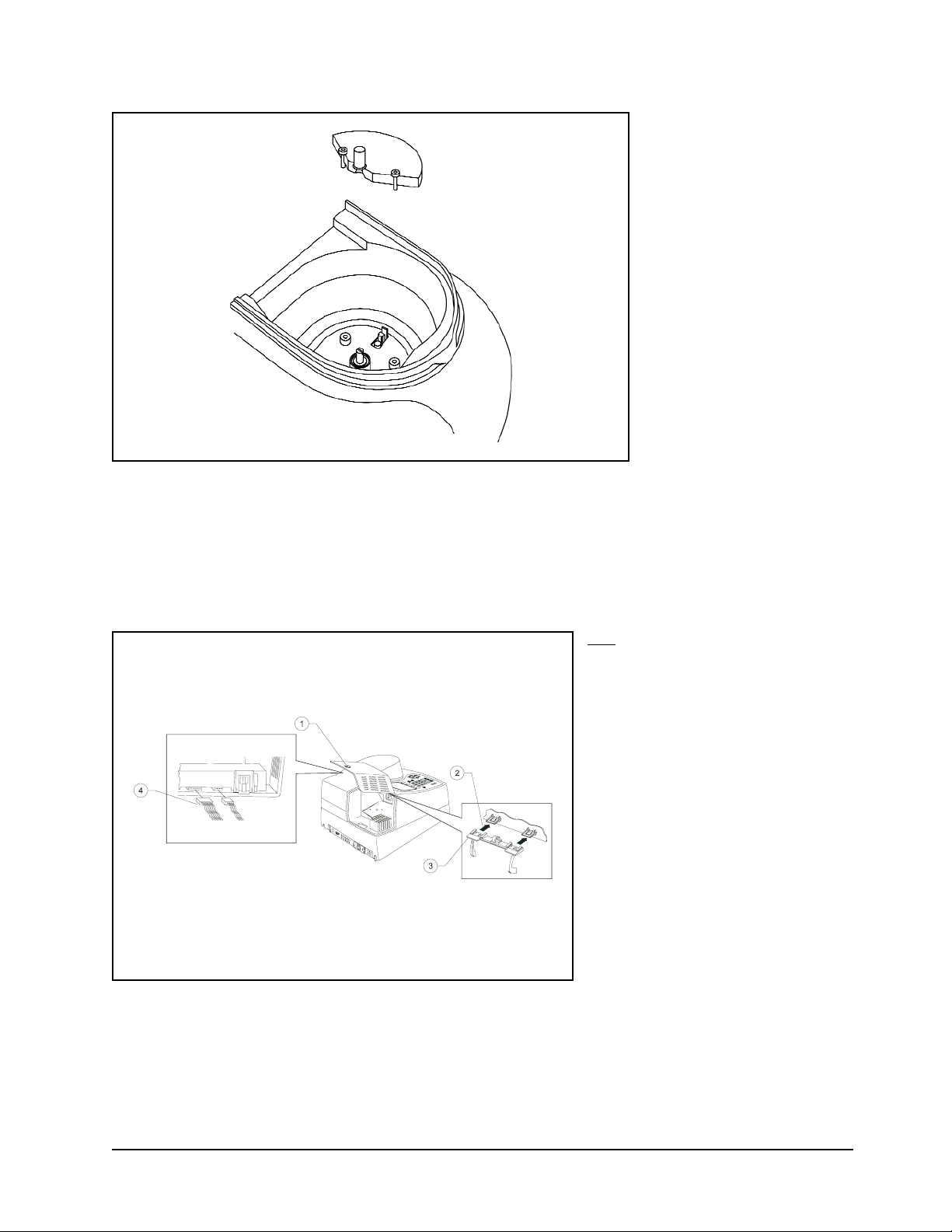
Figure 5 Installing the Single-Position Cell Holder (335916)
Figure 6 Installing the printer (335988)
Key/
c Captive screw on lamp door
d Removing door from hinge
e Hinge
f Connecting wires to printer
Page 6

Figure 7 Removing the cover of the fuse compartment
Figure 8 Removing the fuse holder
Figure 9 Removing and replacing the fuses
Page 7

Declaration of Conformity
(For instruments manufactured after July 1, 2001)
Model: GENESYS™ 10 Series
Catalog Nos.: 335900, 335900A, 335900P, 335900AP, 335901, 335901A, 335901P, 335901AP
335902, 335902A, 335902P, 335902AP, 335903, 335903A, 335903P, 335903AP
335906, 335906P, 335907, 335907P
Model: BioMate™ 3
Catalog Nos.: 335904, 335904P, 335905, 335905P
Model: GENESYS™ 6
Catalog Nos.: 335908, 335908P
North American Plug (NEMA 5-15) Numbers above
European Plug (CEE 7/7 Schuko) Add a –02 suffix
United Kingdom Plug (BS 1363/A) Add a –04 suffix
Thermo Electron Scientific Instrument Corporation certifies that the GENESYS 10, GENESYS 6, and BioMate 3
Spectrophotometers have been tested according to the instrumentation standards listed in this section in compliance
with IEC directives and other regulatory requirements. The equipment under test (EUT) consisted of a sample instrument
and applicable accessories, which are manufactured by Thermo Electron Scientific Instrument Corporation. The EUT
was configured to ensure that both the worst case condition,
and that all of the accessories were tested. This
equipment
has been tested for use in non-residential environments.
IEC Directives
89/336/EEC Electromagnetic Compatibility Directive
73/23/EEC Low Voltage Directive
Electromagnetic Compatibility Test Standards
IEC 61326-1 1998, Electrical Equipment for Measur
ement, Control, and Laboratory use
- EMC Requirements. Class A Limits
IEC 61000-4-2 1999, Electrostatic Discharge Immunity Test (Test level: 4KV Air Discharge and 4 KV Contact Discharge)
IEC 61000-4-3 1998, Radiated, Radio Frequency, Electromagnetic Field Immunity Test (Test level: 3V/m)
IEC 61000-4-4 1995, Electrical Fast Transient/Burst Immunity Test (Test level: 1KV on the supply lines)
IEC 61000-4-5 1995, Surge Immunity Test (Test level: 0.5KV line to line and 1KV line to earth on the supply lines)
IEC 61000-4-6 1996, Immunity to Conducted Disturbances, Induced by Radio-Frequency Fields (Test level: 3V on the supply lines)
IEC 61000-4-11 1994, Voltage Dips, Short Interruptions, and Voltage Variations Test Level: 1 cycle/100%
CISPR 16-2 1999, Specification for Radio Disturbance and
Immunity Measuring Apparatus and Methods
–
Methods of Measurement of Disturbances and Immunity
Safety Test Standards
IEC 61010-1 1990 + A1 1992 +A2 1995. Safety requirements for El
ectrical Equipment for
Measurement, Control and
Laboratory use.
CSA C22.2 No. 1010.1, plus Am 2
IEC 61010-1 1997, Safety requirements for Electrical Equipment for Measuremen
t, Control and Laboratory use;
Part 1: General Requirements Test level: Installation Category II, Pollution Degree 2
Authorized signature:
_______________________________________ ___ Date: ____27May03____
Brenda Wilcox
Vice President, Molecular Spectroscopy
Page 8

Page 9

i BioMate 3 Operator’s Manual
The information in this publication is provided for reference only. All information contained in this publication is believed to be correct and complete. Thermo Electron Scientific Instruments Corporation shall not
be liable for errors contained herein nor for incidental or consequential damages in connection with the furnishing, performance or use of this material. All product specifications, as well as the information contained in this publication, are subject to change without notice.
This publication may contain or reference information and products protected by copyrights or patents and
does not convey any license under our patent rights, nor the rights of others. We do not assume any liability arising out of any infringements of patents or other rights of third parties.
We make no warranty of any kind with regard to this material, including but not limited to the implied warranties of merchantability and fitness for a particular purpose.
Copyright © 2003 by Thermo Electron Scientific Instruments Corporation, Madison, WI 53711. Printed in
the United States of America. All world rights reserved. No part of this publication may be stored in a
retrieval system, transmitted, or reproduced in any way, including but not limited to photocopy, photograph,
magnetic, or other record, without the prior written permission of Thermo Electron Scientific Instruments
Corporation.
For technical assistance, please contact:
THERMO ELECTRON CORPORATION
(North America, Asia Pacific, Middle East, Africa, India and Latin America)
5225 Verona Road, Madison, WI 53711-4495, USA
Telephone: (800) 642-6538 or (608) 276-6373
Fax: (608) 273-5045
E-Mail: careplan.techsupport@thermo.com
THERMO ELECTRON CORPORATION
(Europe)
Mercers Row, Cambridge CB5 8HY, UK
Telephone: Int +44 (0) 1223 446655
Fax: Int +44 (0) 1223 446644
E-Mail: careplan.techsupport@thermo.com
SPECTRONIC is a registered trademark and BioMate is a trademark of Thermo Electron Scientific
Instruments Corporation.
Patent No.: 6414753
Item No.: 335904-10001, Rev. G 06/03
Component No.: 335904-10063, Rev. G 06/03
Page 10

Thermo Electron Corporation ii
GENERAL SAFETY NOTES USED IN THIS MANUAL
This symbol alerts you to important information about using the instrument.
Be sure to read and follow the associated instructions carefully.
This symbol alerts you to potential electrical hazards.
Be sure that only qualified personnel perform the related procedures.
This symbol alerts you to hot surfaces.
Be sure to read and follow the associated instructions carefully.
This symbol alerts you to potential UV radiation exposure, which can cause eye damage.
Wear UV-opaque eye protection..
NEW PRODUCT WARRANTY
Thermo Electron Scientific Instruments Corporation instrumentation and related accessories are warranted
against defects in material and workmanship for a period of one (1) year from the date of delivery. This
warranty is provided only if the warranty registration card is returned to Thermo Electron Scientific
Instruments Corporation within fifteen (15) days after delivery.
This warranty covers parts (except those specified below) and labor, and applies only to equipment which
has been installed and operated in accordance with the operator's reference guide and which has been
serviced only by authorized Thermo Electron Scientific Instruments Corporation dealers or service
personnel. This warranty does not apply to equipment and accessories that have been modified or
tampered with in any way, misused, or damaged by accident, neglect, or conditions beyond Thermo
Electron Scientific Instruments Corporation's control.
This warranty does not apply to lamps, glassware, and similar expendable components. However, such
parts and components may be warranted by their manufacturer.
Thermo Electron Scientific Instruments Corporation is not responsible under this warranty for loss in
operating performance due to environmental conditions.
THIS WARRANTY IS IN LIEU OF ALL WARRANTIES EXPRESSED, IMPLIED, OR STATUTORY,
INCLUDING, BUT NOT LIMITED TO, WARRANTIES OF FITNESS FOR A PARTICULAR PURPOSE OR
MERCHANTABILITY OR OTHERWISE, and states Thermo Electron Scientific Instruments Corporation's
entire and exclusive liability and the Customer's exclusive remedy for any claim in connection with the sale
or furnishing of services, goods, or parts, their design, suitability for use, installation, or operations.
Thermo Electron Scientific Instruments Corporation will in no event be liable for any direct, indirect,
special, or consequential damages, whatsoever, including loss of goodwill, whether grounded in tort
(including negligence), strict liability or contract, and Thermo Electron Scientific Instruments Corporation's
liability under no circumstances will exceed the contract price for the goods and/or services for which
liability is claimed.
Page 11

iii BioMate 3 Operator’s Manua
SOFTWARE PASSWORD
This password allows you to enter the security section of the software used on the Thermo Electron
Corporation spectrophotometer. Through the security section, you can "lock" test setups (test parameters)
so that they may not be altered. The password also allows you to remove the security so that you may edit
the test parameters. Please refer to the appropriate section in this Operator's Manual for more information
on locking a test.
PASSWORD: 4 3 6 3 7 9 7
Page 12

Thermo Electron Corporation iv
Page 13

CHAPTER 1 - Setting Up the Instrument
Setting up the instrument.................................................................................................................1-1
Setting utility parameters ...........................................................................................................1-1
Selecting the language ..............................................................................................................1-1
Setting the date and time ..........................................................................................................1-2
Selecting standby settings.........................................................................................................1-2
Setting baseline expiration time ................................................................................................1-2
Setting the screen contrast........................................................................................................1-2
Loading paper in the internal printer.........................................................................................1-2
Setting the utility parameters for the printer .............................................................................1-3
Selecting and positioning glassware...............................................................................................1-3
Z-dimensions ....................................................................................................................................1-4
CHAPTER 2 - Using “Biotests” Software
Overview ...........................................................................................................................................2-1
Table of parameters ...................................................................................................................2-1
Entering information & commands..................................................................................................2-1
Types of parameter entries........................................................................................................2-1
Keypad layout.............................................................................................................................2-1
SmartStart feature ............................................................................................................................2-2
Setting up a single-test SmartStart ...........................................................................................2-2
Setting up a multiple-test SmartStart ........................................................................................2-2
Nucleic acid measurements ............................................................................................................2-2
DNA (260/280 and DNA 260/230) ............................................................................................2-3
DNA with Scan (260/280) and DNA with Scan (260/230).......................................................2-4
dsDNA, ssDNA, RNA and Oligos (entered factor) Direct or UV Measurements...................2-5
Protein Measurements.....................................................................................................................2-8
Bradford (standard & micro), Lowry (standard & micro), BCA (standard & micro) and Biuret
measurements ...........................................................................................................................2-8
Direct UV (280) and Direct UV (205)........................................................................................2-9
Warburg-Christian....................................................................................................................2-10
Cell Growth .....................................................................................................................................2-11
Setting test parameters ...........................................................................................................2-11
Measuring the sample .............................................................................................................2-11
Oligo Calculator..............................................................................................................................2-12
Using the oligo calculator ........................................................................................................2-12
CHAPTER 3 - Using “General Tests” Software
General information..........................................................................................................................3-1
Editing and Loading Saved Tests .............................................................................................3-1
Specifying names for tests ........................................................................................................3-1
Specifying concentration units...................................................................................................3-1
Using the SmartStart feature.....................................................................................................3-2
Running the cell correction program.........................................................................................3-3
Taking measurements ...............................................................................................................3-5
Saving tests ................................................................................................................................3-5
Basic Absorbance/%T measurements............................................................................................3-6
Setting the wavelength ..............................................................................................................3-6
Table of Contents
v BioMate 3 Operator’s Manua
Page 14

Table of Contents
Measuring a blank......................................................................................................................3-6
Measuring unknowns.................................................................................................................3-6
Basic Concentration measurements...............................................................................................3-6
Setting the wavelength & mode................................................................................................3-7
Measuring a blank......................................................................................................................3-7
Measuring a standard................................................................................................................3-7
Entering a factor.........................................................................................................................3-8
Measuring unknowns.................................................................................................................3-8
Advanced A/%T/C - Absorbance & %Transmittance measurements ..........................................3-8
Recalling a test...........................................................................................................................3-8
Setting up test parameters ........................................................................................................3-9
Taking measurements ...............................................................................................................3-9
Advanced A/%T/C - Concentration measurements.......................................................................3-9
Recalling a test.........................................................................................................................3-10
Setting up test parameters ......................................................................................................3-10
Measuring a standard..............................................................................................................3-10
Entering a factor .......................................................................................................................3-11
Measuring unknowns...............................................................................................................3-11
Standard Curve...............................................................................................................................3-11
Recalling a standard curve......................................................................................................3-11
Setting the parameters for a standard curve..........................................................................3-12
Measuring the standards for a standard curve......................................................................3-12
Measuring unknowns...............................................................................................................3-13
Editing a standard curve..........................................................................................................3-13
Absorbance Ratio...........................................................................................................................3-13
Recalling a test.........................................................................................................................3-14
Setting up test parameters ......................................................................................................3-15
Measuring unknowns...............................................................................................................3-15
Absorbance Difference ..................................................................................................................3-16
Recalling a test.........................................................................................................................3-16
Setting up test parameters ......................................................................................................3-16
Measuring unknowns...............................................................................................................3-16
Kinetics............................................................................................................................................3-17
Recalling a test.........................................................................................................................3-17
Setting up test parameters ......................................................................................................3-17
Measuring unknowns...............................................................................................................3-17
Rescaling & recalculating kinetics results ..............................................................................3-18
Rescaling & recalculating tabular kinetics results..................................................................3-19
Survey Scan/Scanning ..................................................................................................................3-20
Recalling a test.........................................................................................................................3-20
Setting up test parameters ......................................................................................................3-20
Collecting a baseline scan.......................................................................................................3-20
Scanning an unknown.............................................................................................................3-21
Viewing & manipulating scan data..........................................................................................3-21
3-Point Net......................................................................................................................................3-24
Recalling a test.........................................................................................................................3-24
Setting up test parameters ......................................................................................................3-24
Thermo Electron Corporation vi
Page 15

Taking measurements .............................................................................................................3-24
Multiple Wavelengths.....................................................................................................................3-25
Recalling a test.........................................................................................................................3-25
Setting up test parameters ......................................................................................................3-26
Taking measurements .............................................................................................................3-26
CHAPTER 4 - Using the Performance Validation Program
Overview ...........................................................................................................................................4-1
Accessing the Performance Validation tests ..................................................................................4-1
Troubleshooting checklist.................................................................................................................4-1
Wavelength Accuracy - Internal.......................................................................................................4-1
Wavelength Accuracy - Standards..................................................................................................4-2
Adding wavelengths...................................................................................................................4-2
Deleting wavelengths.................................................................................................................4-3
Photometric Accuracy ......................................................................................................................4-3
Selecting the mode ....................................................................................................................4-3
Adding standards .......................................................................................................................4-3
Deleting standards .....................................................................................................................4-4
Running the test .........................................................................................................................4-4
Noise Measurement.........................................................................................................................4-4
Stray Light.........................................................................................................................................4-5
Running the test .........................................................................................................................4-5
Internal Printer Test ..........................................................................................................................4-5
RS232C Test ....................................................................................................................................4-6
CHAPTER 5 - Connecting & Using Accessories
General information..........................................................................................................................5-1
Cell holders & cell holder accessories ............................................................................................5-1
Changing cell holders ................................................................................................................5-2
Internal printer...................................................................................................................................5-3
Installing the internal printer.......................................................................................................5-3
Loading paper in the internal printer.........................................................................................5-3
External computers ..........................................................................................................................5-3
CHAPTER 6 - Performing Maintenance Procedures
Routine care .....................................................................................................................................6-1
Cleaning............................................................................................................................................6-1
Cleaning and maintenance of cells...........................................................................................6-1
Cleaning the windows of the sample compartment.................................................................6-2
Changing the fuse ............................................................................................................................6-2
Replacement parts ...........................................................................................................................6-3
Table of Contents
vii BioMate 3 Operator’s Manua
Page 16

Table of Contents
Appendix A - Specifications
Appendix B - Parameters
Appendix C - Calculations
Index
Thermo Electron Corporation viii
Page 17
Setting up the instrument
1. Carefully unpack the shipping carton and verify
that you have received all the items listed
below.
• BioMate 3 spectrophotometer
• Power cord
• Operator's Manual - BioMate 3
spectrophotometer
• Dust cover
• Single Cell Holder
Models shipped with internal printer installed
will also include:
• 1 roll of printer paper
• 1 printer holder set
2. Place the instrument on a flat, even surface
that is:
• As far as possible from any strong electric
or magnetic fields and from any electrical
device that may generate high-frequency
fields
• Free of dust, corrosive gases and strong
vibrations
3. Remove any obstructions or materials that
could hinder the flow of air under, behind and
around the instrument.
4. Connect the female end of the power cord into
the connector labeled A/C power on the back
panel of the instrument (see Figure 2).
5. Plug the other end of the power cord into a
grounded outlet with the appropriate voltage.
6. Ensure that the sample compartment does not
contain any samples, and that the sample
compartment door is closed.
7. Snap the paper roll holders (if needed) into
place as shown in Figure 3. They will fit flush
with the top of the instrument.
8. Turn on the instrument by pressing the power
switch to ON (1=ON, 0=OFF). The power-on
sequence will appear on the display and the
instrument will go through its self-diagnostics.
The instrument performs these diagnostics in
the sequence shown:
a) Logo
b) Initializing
c) Calibrating filter wheel
d) Finding zero order
e) Finding energy peak
f) Calibrating grating
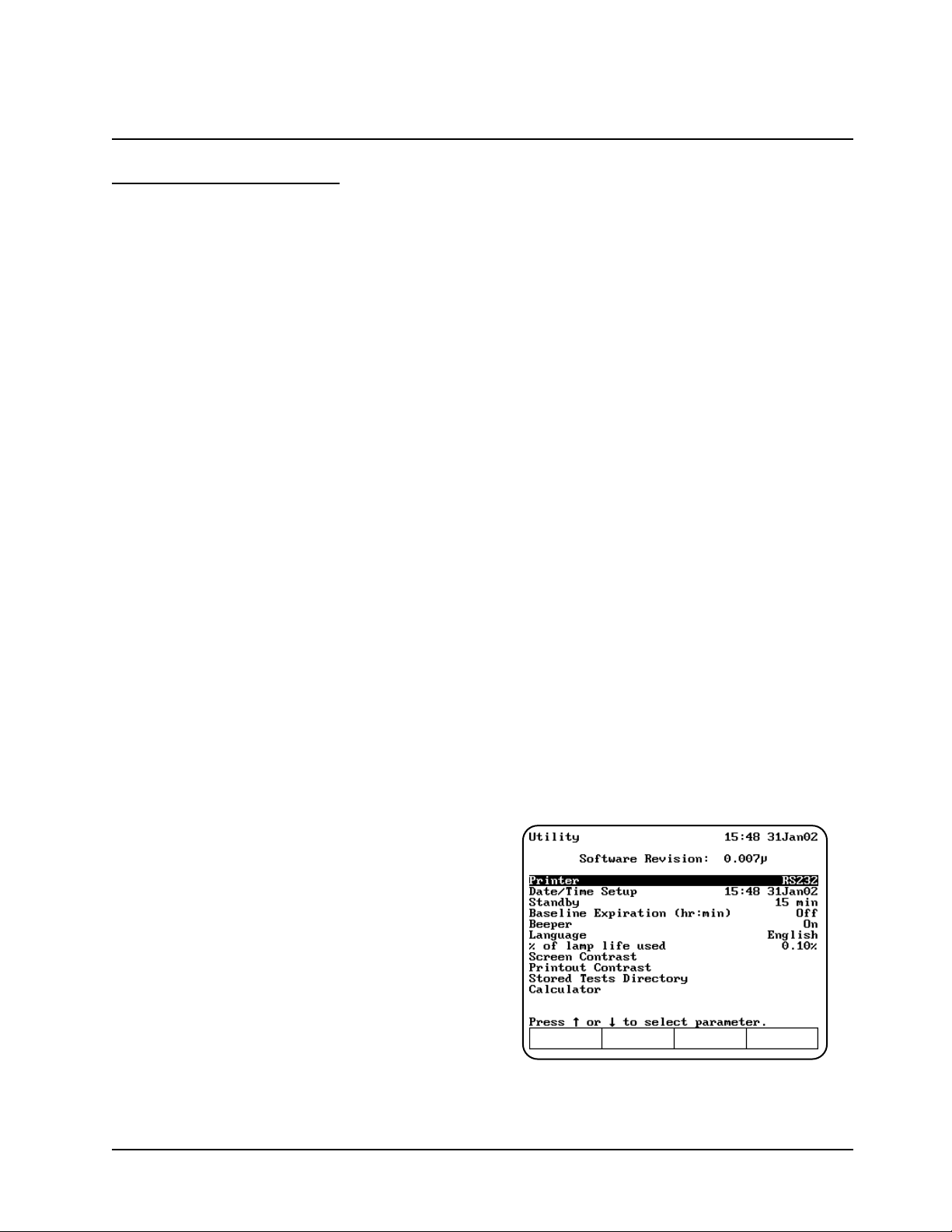
Setting utility parameters
You should set up some of the utility parameters
after the instrument is first powered up. These
parameters include the date and time, standby
setting, language, screen contrast settings and
parameters needed to set up the printer.
You can set up the other utility parameters, or
change the utility settings, at any time except when
an entry screen is displayed or when the
instrument is carrying out a task (such as setting
the blank).
• Press the UTILITY key. The Utility screen
appears on the display.
From this screen, you can set the date and time,
select the standby settings, select the language,
reset the lamp hours, select the contrast settings
and select the parameters for a printer.
Selecting the language
The instrument supports English, Spanish, French,
German and Italian as the language options.
• With the Utility screen displayed, press the
arrow keys to highlight Language and press
ENTER.
• Press the arrow keys to highlight the language
you want to select and press ENTER.
Setting Up the Instrument
1-1 BioMate 3 Operator’s Manual
Page 18

Setting the date and time
To access the date and time settings:
• With the Utility screen displayed, press the
arrow keys to highlight Date/Time Setup and
press ENTER. The screen displays the three
date/time options that you can modify - date,
time format and time.
To set the date:
• Press the arrow keys to highlight Set Date and
press ENTER.
• Press Set Day, type the date, then press
ENTER.
• Press Set Month, highlight the correct month,
then press ENTER.
• Press Set Year, type the year, then press
ENTER.
• When the date is correct, press ESC to save
the settings and return to the Utility screen.
To select the time format:
You can set up the spectrophotometer to display
the time in either am/pm format or in 24-hour
format.
• To change the display format for the time,
press the arrow keys to highlight Time Format
and press ENTER until the format that you
want to use (AM/PM or 24 hour) appears.
To set the time:
• Press the arrow keys to highlight Set Time and
press ENTER.
• To set the hour, press Set Hour, type in the
hour and press ENTER.
• To set the minutes, press Set Minute, type in
the minute and press ENTER.
• To select between AM and PM, press Set
AM/PM until the appropriate setting appears.
Note: Any changes you make are saved
automatically (even during power down) by
battery backup.
Selecting standby settings
To prolong xenon lamp life, your
spectrophotometer has been pre-set at the factory
to automatically go into standby mode after 15
minutes. To change Standby Mode time:
• With the Utility screen displayed, press the
arrow keys to highlight Standby and press
ENTER.
• Press the arrow keys to highlight the length of
time you want the instrument will wait before
entering standby mode and press ENTER.
Setting baseline expiration time
If you will be performing scans on your samples,
you can set a time limit for a collected baseline.
To set the baseline expiration time:
• With the Utility screen displayed, press the
arrow keys to highlight Baseline Expiration
(hr:min) and press ENTER.
• Enter the desired time into the Entry baseline
expiration time field. Press ENTER.
Setting the screen contrast
To make it easier to read the display, you can
adjust the screen contrast on the spectrophotometer.
• With the Utility screen displayed, press the
arrow keys to highlight Screen Contrast and
press ENTER.
• Press the arrow keys to adjust the screen
contrast.
• When the screen contrast is correct, press ESC.
Setting up the internal printer
To set up the printer properly, you need to load the
paper and set the utility parameters for the printer.
Before setting up the parameters for the printer, be
sure that the printer is installed. If you have
ordered the internal printer as a separate item, you
will need to install it. Refer to the section
Connecting & using accessories for instructions on
installing the printer.
Loading paper in the internal printer
Note: Make sure that the paper roll holders are in
place as shown in Figure 3. When installed
correctly, they will fit flush with the top of
the instrument.
• Cut the paper so the edge is even.
Note: Arrows on the paper roll holders indicate
the direction of the paper feed (see
Figure 3).
Setting Up the Instrument
Thermo Electron Corporation 1-2
Page 19
• Feed the paper straight into the paper entry
slot. The printer grabs the end of the paper and
pulls it in.
• In Basic Absorbance/%Transmittance (%T),
when the paper stops, press ENTER to
continue advancing the paper until the paper
comes out of the paper exit slot.
• Pull out on the finger tabs on the paper roll
holders and secure the roll of paper onto the
paper roll holder.
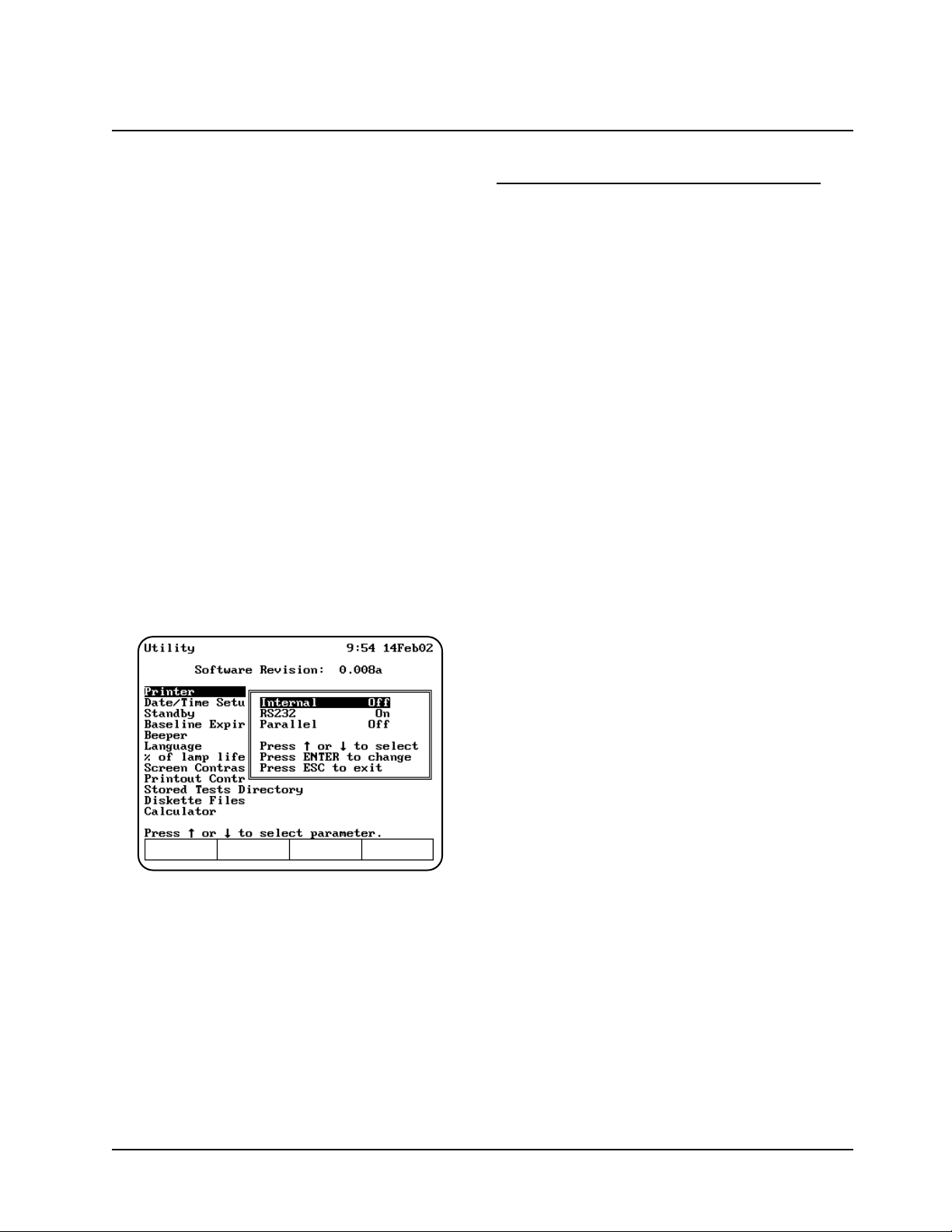
Setting the utility parameters for the printer
If you wish to use a printer you can output to:
• Internal printer.
• External RS232 printer.
To ensure that the spectrophotometer can output
information correctly to the printer, you need to
select the appropriate device.
• Press the UTILITY key. The Utility screen
appears on the display.
• Press the arrow keys to highlight Printer and
press ENTER.
• Select the printer that you want to use and
press ENTER until On appears.
• Press ESC to save the settings and return to
the Utility screen.
Selecting and positioning glassware
The wavelength range for different types of cells
varies depending on the manufacturer:
• Glass - From 320 to 360nm, up to 1100nm.
• Quartz - From 190 to 230nm, up to
1100nm.
• Disposable - Refer to manufacturer's
specifications and ensure that you work
within the recommended range.
Test tubes vs. cuvettes
• Square cuvettes that are carefully matched
(see “Correcting for cell variability” below) yield
very precise results. Matched test tubes, when
properly handled, can show as little as 1-2%
deviation between readings.
• The pathlength of test tubes is not as well
defined as in square cuvettes. However,
constructing a standard curve eliminates the
need for great accuracy in knowing the
pathlength, provided that the same pathlength
cell is used for all blanks, standards and
samples.
Other guidelines
• Be sure to position cuvettes and test tubes so
that the clear sides face the light beam. This
means that one clear side should face the front
of the instrument and the other clear side
should face the back of the instrument.
Note: Test tubes should always be placed in the
instrument in exactly the same orientation
in the light beam. A fiducial mark on the
test tube helps you orient the test tubes
consistently and correctly.
• When using small aperture cells:
• Always use masked cells.
• Use the same cell (or cuvette) for your
blank and your samples.
Setting Up the Instrument
1-3 BioMate 3 Operator’s Manual
Page 20
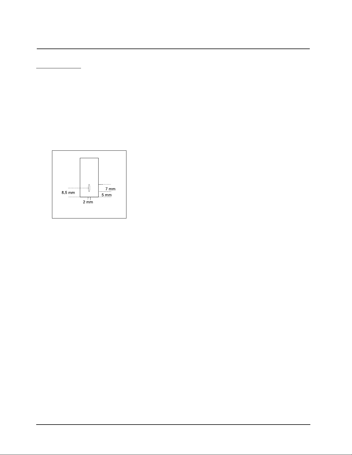
Z-dimensions
The figure below illustrates the position of the light
beam in the spectrophotometer.
The specifications for the sample compartment,
including the dimensions of the beam are:
• Z-dimension
• Square cuvettes/Test tubes 8.5mm
• Beam size 2mm (wide) x 7mm (high)
Setting Up the Instrument
Thermo Electron Corporation 1-4
Page 21
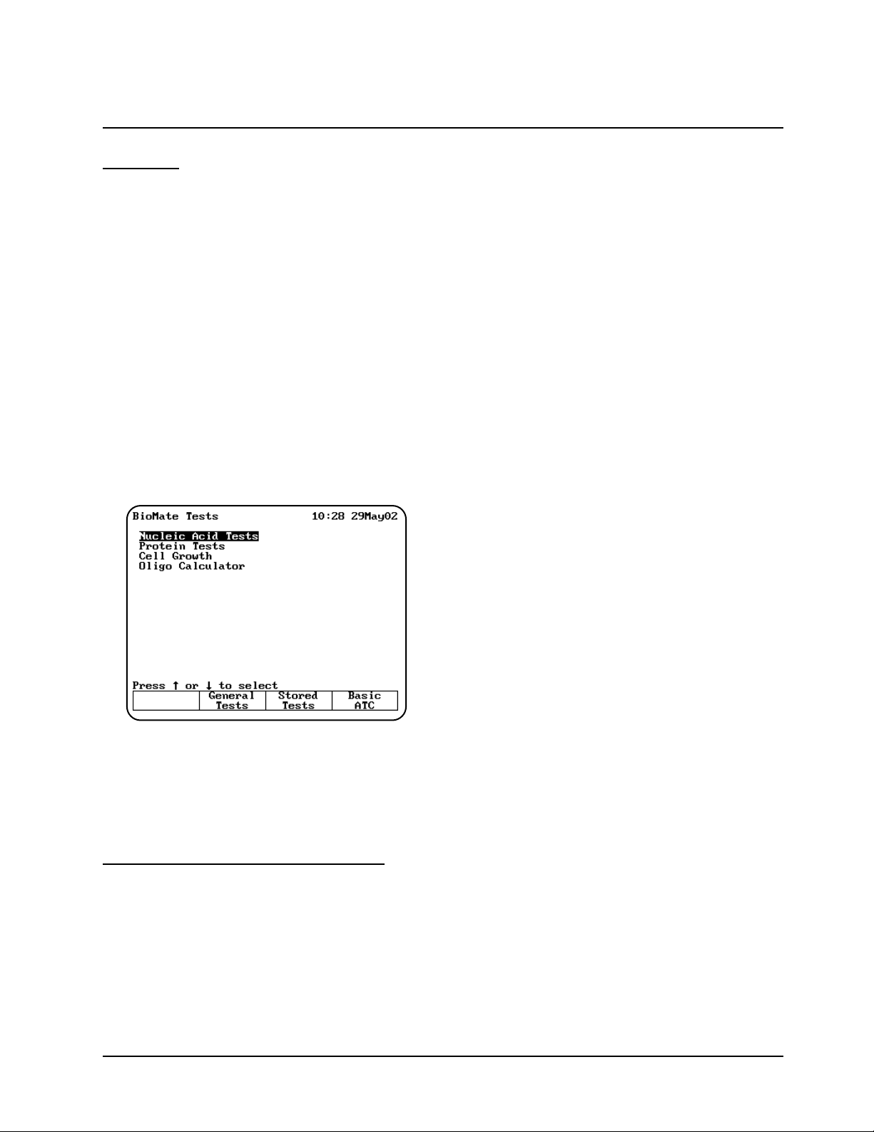
Overview
The BioMate instrument allows you to run an
assortment of tests used to characterize biological
and biochemical substances. These tests fall into
the following categories:
• Nucleic acid measurements
• Protein measurements
• Cell growth analysis
• Oligonucleotide calculations
All of the parameters for the BioMate applications
described in this chapter are factory-set. This
means that if you want to change the parameters,
you will need to specify a different name to save
the new test parameters.
Turn on your spectrophotometer. After the poweron sequence is completed, the list of BioMate test
categories appears.
Table of parameters
Parameters used in the spectrophotometer are
located in Appendix B.
You can use this list as a reference when you are
setting up tests.
Entering information & commands
The keypad on the spectrophotometer includes a
numeric keypad as well as certain special keys that
you can use to enter information and commands.
Types of parameter entries
Different parameters require different types of
entries - you can select from a list for some
parameters, while you need to enter a value for
others. While using the spectrophotometer, you will
notice the following types of entries for parameters:
• Type-in entries are numeric values that you
can enter using the numeric keypad.
• Toggle entries offer two options for a
parameter. You can press ENTER to switch
between the two options, then press one of the
arrow keys to move to another parameter.
• Pop-up windows list multiple options for a
parameter or display messages. You can press
the arrow keys to select the value you want,
then press ENTER to select it and move to
another parameter.
• Cursor selections are used on graphical
displays and the character list you use to name
tests and files. On graphical displays, the cursor
appears as a vertical line; on the character list,
the cursor highlights the character where it is
positioned. You use the cursor control keys to
move the cursor to the character or position on
the graph you want to select.
Keypad layout
The keypad on the spectrophotometer (shown in
Figure 4) includes a numeric keypad as well as the
following special keys:
• Function keys - These four keys allow you to
select a particular task you want to perform.
The tasks you can perform appear on the
display screen above each key and vary from
one screen to another. On some screens, all
four keys will function, while on other screens
only some of the function keys will work.
• Esc - In general, when you press ESC, the
program clears the current entry but does not
change any values you have already accepted.
The program may also return you to the
previous screen when you press ESC.
• Clear - When you press CLEAR, the program
deletes any entry you have made but does not
change any values you have already accepted.
The program does not return you to the
previous screen when you press CLEAR.
• Enter - Typically, when you press ENTER, the
program accepts any highlighted or selected
values and advances to the next parameter or
screen. Specific instructions later in this guide
indicate any special instructions about using
ENTER.
Using “Biotests” Software
2-1 BioMate 3 Operator’s Manua
Page 22

• Arrow keys - These keys allow you to control
the position of the cursor so you can select values
from lists or select an option from a screen.
• Cell position keys - These keys allow you to
select which cell position the instrument will
use for a measurement. If you have the optional
turret installed, one position is reserved for
your blank and you can select from five cell
positions for your samples.
• Utility - When you press UTILITY, the Utility
screen appears on the display.
• Test - When you press TEST, the Test Types
screen appears on the display.
• Print - When you press PRINT, the instrument
prints the information that appears on the display.
SmartS
tart feature
BioMate’s SmartStart feature enables you to select
the test methods you use most frequently and have
them appear when you start up your instrument. If
your laboratory runs only a single test, you can use
the SmartStart feature to select it and it will appear
each time you start up your instrument. Similarly, if
you have a set of tests you run, you can use
SmartStart to select them so the list appears when
you start up the instrument.
Setting up a single-test SmartStart
1. With the BioMate Tests Screen displayed,
press the Stored Tests key on the
spectrophotometer keypad. A list of all the tests
on the instrument appears on the screen.
2. Scroll down through the list until the
appropriate test is highlighted.
3. When the appropriate test is highlighted, press
Select Test to add the selected test to the
SmartStart menu. An arrow sign “>” will
indicate the test has been selected
4. Press Load Test.
5. The parameter screen of the test you selected
will be displayed.
Note: At this point, you can power down the
instrument and then power it back up.
When it starts up again, the parameter
screen for the selected test will be
displayed.
Setting up a multiple-test SmartStart
1. Press the Stored Tests key on the
spectrophotometer keypad.
2. Scroll down through the list until the first
appropriate test is highlighted.
3. Press Select Tests to add the selected test to
the SmartStart menu.
4. Continue scrolling through the list and adding
tests until you’ve made all the appropriate
selections.
5. Press ESC until you return to the BioMate
Tests screen.
Note: At this point, you can power down the
instrument and then power it back up.
When it starts up again, the list of tests
you’ve selected will be displayed.
Nucleic acid measurement
s
You can use these tests to determine the
concentration and purity of nucleic acid in a given
sample.
• DNA - measures absorbance at 260 and
280nm; determines concentration and purity
based on absorbance ratio and absorbance
difference; also calculates protein
concentration.
• DNA with scan - records absorbance scan
between 260 and 280nm or between 260 and
230nm; determines concentration and purity
based on absorbance ratio and absorbance
concentration; also calculates protein
concentration.
• dsDNA - measures absorbance at 260nm;
calculates concentration based on absorbance
and concentration factor.
• ssDNA, RNA - measures absorbance at
260nm; calculates concentration based on
absorbance and concentration factor.
• Oligonucleotides ("Oligos") - measures
absorbance at 260nm; calculates concentration
based on absorbance and concentration factor
or calculates concentration based on
absorbance and concentration factor
determined by oligo calculator.
Using “Biotests” Software
Thermo Electron Corporation 2-2
Page 23
Several of these categories include multiple tests
that are similar, so the section may not include
screen samples for each test. For example, the
parameters are the same for the Direct UV
measurement of ssDNA and RNA tests, but the
factor used to convert absorbance to concentration
is different. Similarly, for the Direct UV
measurement of oligonucleotides tests, the
parameters are also the same, but the factors used
to convert absorbance to concentration are
different. For a complete list of all parameters and
calculations for each test, refer to Appendices B
and C.
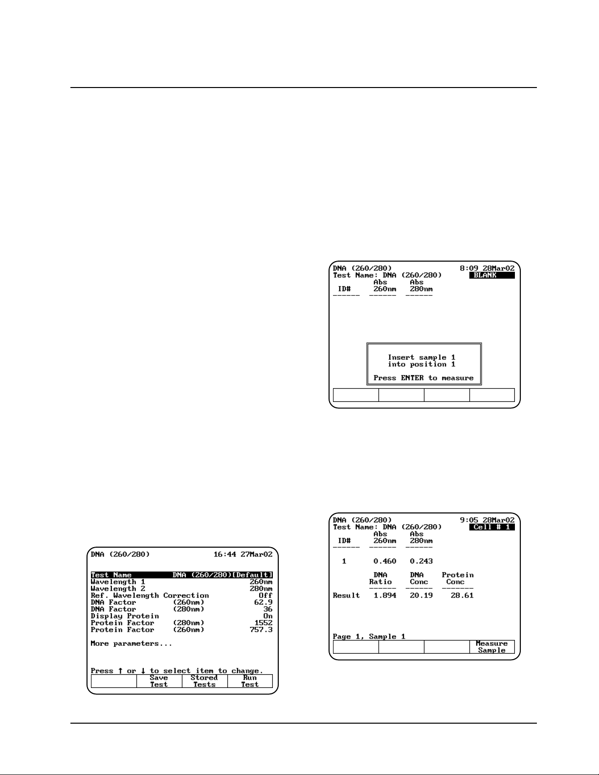
DNA (260/280) and DNA (260/230)
These tests function almost identically - the only
difference is the wavelengths used for the
measurements. One test measures absorbance at
260 and 280nm, while the other measures
absorbance at 260 and 230nm. Refer to Appendix
B for a description of the parameters and Appendix
C for the default values.
To get started, with the BioMate Tests screen
displayed, move the arrow keys to highlight
Nucleic Acid Tests and press ENTER. A list of
nucleic acid test appears. Move the arrow keys to
highlight DNA (260/280). The DNA (260/280)
parameter screen appears.
Note: The following screens show the
parameters for the DNA (260/280) test.
For the DNA (260/230) test, Wavelength 2
is set to 230nm.
Note: If Cell Correction is ON, you must run the
Setup Correction program before you can
access the Run Test or Measure
Samples keys.
Setting up test parameters
1. With the DNA (260/280) or DNA (260/230)
screen displayed, use the arrow keys to
highlight the name of the parameter you want
to set.
2. When the parameters are set, you can press
Save Test to save the test or Run Test to
measure the blank and unknowns.
Measuring unknowns
Measuring unknowns automatically (using Auto 6
or Auto 3)
1. Place the blank and unknowns in the correct
cell positions.
2. Press ENTER to start the measurements. The
instrument automatically measures the blank
first, then measures the unknowns and
displays the sample measurements on the
screen.
Using “Biotests” Software
2-3 BioMate 3 Operator’s Manual
Page 24

Measuring unknowns manually (using Manual 6 or
Single Cell Positioner)
1. With the DNA setup screen displayed, press
Run Test.
2. Place the blank and unknown in the correct cell
positions. If your instrument is equipped with a
6-Position Cell Holder, you can place up to five
samples in the cell holder.
3. Press Measure Blank to measure the blank. If
your instrument is equipped with a 6-Position
Cell Holder, it automatically moves to the B
position to measure the blank. When it
completes the measurement, it returns to its
previous cell position.
4. Press Measure Sample to start the
measurement. If your instrument is equipped
with a 6-Position Cell Holder, press the cell
position buttons on the keypad to re-position
the cell holder and measure the rest of the
unknowns manually.
DNA with Scan (260/280) and DNA with Scan
(260/230)
The DNA measurement with scan tests include two
test that function almost identically - the only
difference is in the wavelengths used for the
measurements. In both cases the scan is
measured from 225 to 325nm. One test measures
absorbance at 260 and 280nm, while the other
measures absorbance at 260 and 230nm. Refer to
Appendix B for a description of the parameters and
Appendix C for the default values.
To get started, with the BioMate Tests screen
displayed, move the arrow keys to highlight
Nucleic Acid Tests and press ENTER. A list of
nucleic acid test appears. Move the arrow keys to
highlight DNA with Scan (260/280). The DNA with
Scan (260/280) parameter screen appears.
Note: The following screens show the
parameters for the DNA (260/280) test.
For the DNA (260/230) test, Wavelength 2
is set to 230nm.
Note: If Cell Correction is ON, you must run the
Setup Correction program before you can
access the Run Test or Measure
Samples keys.
Setting up test parameters
1. With the DNA with Scan (260/280) or DNA
with Scan (260/230) screen displayed, use the
arrow keys to highlight the name of the
parameter you want to set.
2. When the parameters are set, you can press
Save Test to save the test or Run Test to
measure the blank and unknowns.
Collecting a baseline scan
Note: If your instrument is equipped with a 6-
Position Cell Holder, be sure to place the
blank in the B position. The instrument
always uses the B position to collect the
baseline.
1. With the DNA with Scan (260/280) or DNA
with Scan (260/230) screen displayed, press
Run Test. The DNA with Scan measurement
screen appears.
Using “Biotests” Software
Thermo Electron Corporation 2-4
Page 25
2. Place the blank in the B position.
3. Press Measure Blank to collect the baseline.
When the instrument is finished measuring the
blank, the message disappears.
Note: If you want to switch between tabular and
graphical displays, press Graph or
Tabular.
Measuring the sample
1. If your instrument is equipped with a 6-Position
Cell Holder, be sure to place the unknown in
cell position #1.
Note: The instrument always uses cell position
#1 to measure the sample.
2. With the DNA with Scan measurement screen
displayed, press Measure Sample to measure
the sample. When the instrument is finished
measuring the absorbance scan, it displays a
graph of the scan along with the sample ID#,
DNA ratio, DNA concentration and protein
concentration.
Note: If you want to switch between tabular and
graphical displays, press Graph or
Tabular.
Note: You may need to use the up and down
arrow keys to view all the data for the
screen.
dsDNA, ssDNA, RNA and Oligos (entered
factor) Direct or UV Measurements
These test measurements are all set up and run
using the same types of test parameters. Refer to
Appendix B for a description of the parameters and
Appendix C for the default values.
To get started, with the BioMate Tests screen
displayed, move the arrow keys to highlight
Nucleic Acid Tests and press ENTER. A list of
nucleic acid test appears. Move the arrow keys to
highlight the desired test and press ENTER. The
dsDNA, ssDNA, RNA or Oligos (entered factor)
parameter screen appears.
Note: The following screens show the
parameters for the dsDNA test.
Note: If Cell Correction is ON, you must run the
Setup Correction program before you can
access the Run Test or Measure
Samples keys.
Using “Biotests” Software
2-5 BioMate 3 Operator’s Manual
Page 26
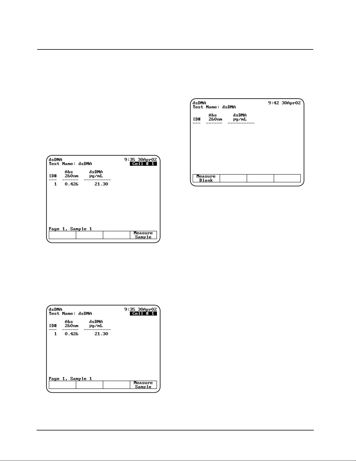
Setting up test parameters
1. With the dsDNA, ssDNA, RNA or Oligos
setup screen displayed, use the arrow keys to
highlight the name of the parameter you want
to set.
2. When the parameters are set, you can press
Save Test to save the test or Run Test to
measure the blank and unknowns.
Measuring unknowns
Measuring unknowns automatically (using Auto 6
or Auto 3)
1. Place the blank and unknowns in the correct
cell positions.
2. Press ENTER to start the measurements. The
instrument automatically measures the blank
first, then measures the unknowns and
displays the sample measurements on the
screen.
Measuring unknowns manually (using Manual 6 or
Single Cell Positioner)
1. With the dsDNA setup screen displayed, press
Run Test.
2. Place the blank and unknown in the correct cell
positions. If your instrument is equipped with a
6-Position Cell Holder, you can place up to five
samples in the cell holder.
3. Press Measure Blank to measure the blank. If
your instrument is equipped with a 6-Position
Cell Holder, it automatically moves to the B
position to measure the blank. When it
completes the measurement, it returns to its
previous cell position.
4. Press Measure Sample to start the
measurement. If your instrument is equipped
with a 6-Position Cell Holder, press the cell
position buttons on the keypad to re-position
the cell holder and measure the rest of the
unknowns manually.
Oligos (calculated factor)
The Oligos (calculated factor) measurement
calculates molecular weight, extinction coefficient
and a conversion factor for a base sequence that
you enter. This conversion factor is used to
calculate the concentration of oligos in your sample
from the absorbance measurement. Refer to
Appendix B for a description of the parameters and
Appendix C for the default values.
Using “Biotests” Software
Thermo Electron Corporation 2-6
Page 27
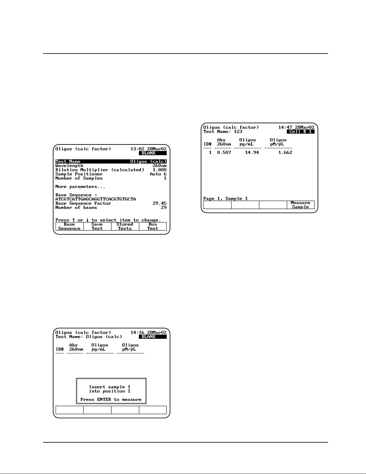
To get started, with the BioMate Tests screen
displayed, move the arrow keys to highlight
Nucleic Acid Tests and press ENTER. A list of
nucleic acid test appears. Move the arrow keys to
highlight the desired test and press ENTER. The
Oligos (calc factor) parameter screen appears.
Note: If Cell Correction is ON, you must run the
Setup Correction program before you can
access the Run Test or Measure
Samples keys.
Setting up test parameters
1. With the Oligos (calc factor) setup screen
displayed, use the arrow keys to highlight the
name of the parameter you want to set.
2. When the parameters are set, you can press
Save Test to save the test or Run Test to
measure the blank and unknowns.
Measuring unknowns
Measuring unknowns automatically (using Auto 6
or Auto 3)
1. Place the blank and unknowns in the correct
cell positions.
2. Press ENTER to start the measurements. The
instrument automatically measures the blank
first, then measures the unknowns and
displays absorbance, oligo concentration in
µg/mL and pmol/µL.
Measuring unknowns manually (using Manual 6 or
Single Cell Positioner)
1. With the Oligos (calc factor) screen
displayed, press Run Test.
2. Place the blank and unknown in the correct cell
positions. If your instrument is equipped with a
6-Position Cell Holder, you can place up to five
samples in the cell holder.
3. Press Measure Blank to measure the blank. If
your instrument is equipped with a 6-Position
Cell Holder, it automatically moves to the B
position to measure the blank. When it
completes the measurement, it returns to its
previous cell position.
4. Press Measure Sample to start the
measurement. If your instrument is equipped
with a 6-Position Cell Holder, press the cell
position buttons on the keypad to re-position
the cell holder and measure the rest of the
unknowns manually.
Using “Biotests” Software
2-7 BioMate 3 Operator’s Manual
Page 28
Protein Measurements
Bradford (standard & micro), Lowry (standard &
micro), BCA (standard & micro) and Biuret
measurements
You can use these tests to determine the
concentration of protein in a given sample, using
the following analytical methods:
Bradford - measures absorbance at 595nm;
determines concentration for either standard or
micro sample concentrations.
Lowry - measures absorbance at 550nm for
standard and 770nm for micro; determines
concentration for either standard or micro sample
concentrations.
Bicinchoninic Acid (BCA) - measures
absorbance at 562nm; determines concentration
for either standard or micro sample concentrations.
Biuret - measures absorbance at 540nm.
Several of these categories include multiple tests
that are similar, so this section includes screen
samples for the standard Bradford test only. For a
complete list of all parameters for each test, refer
to Appendix B; for a list of calculations used for the
tests, refer to Appendix C.
To get started, with the BioMate Tests screen
displayed, move the arrow keys to highlight
Protein Tests and press ENTER. A list of protein
tests appears. Move the arrow keys to highlight the
desired test and press ENTER. The Bradford-
Standard parameter screen appears.
Note: The following screens show the
parameters for the Bradford-Standard test.
All the other protein standard curve
methods work in a similar fashion.
Note: If Cell Correction is ON, you must run the
Setup Correction program before you can
access the Run Test or Measure
Samples keys.
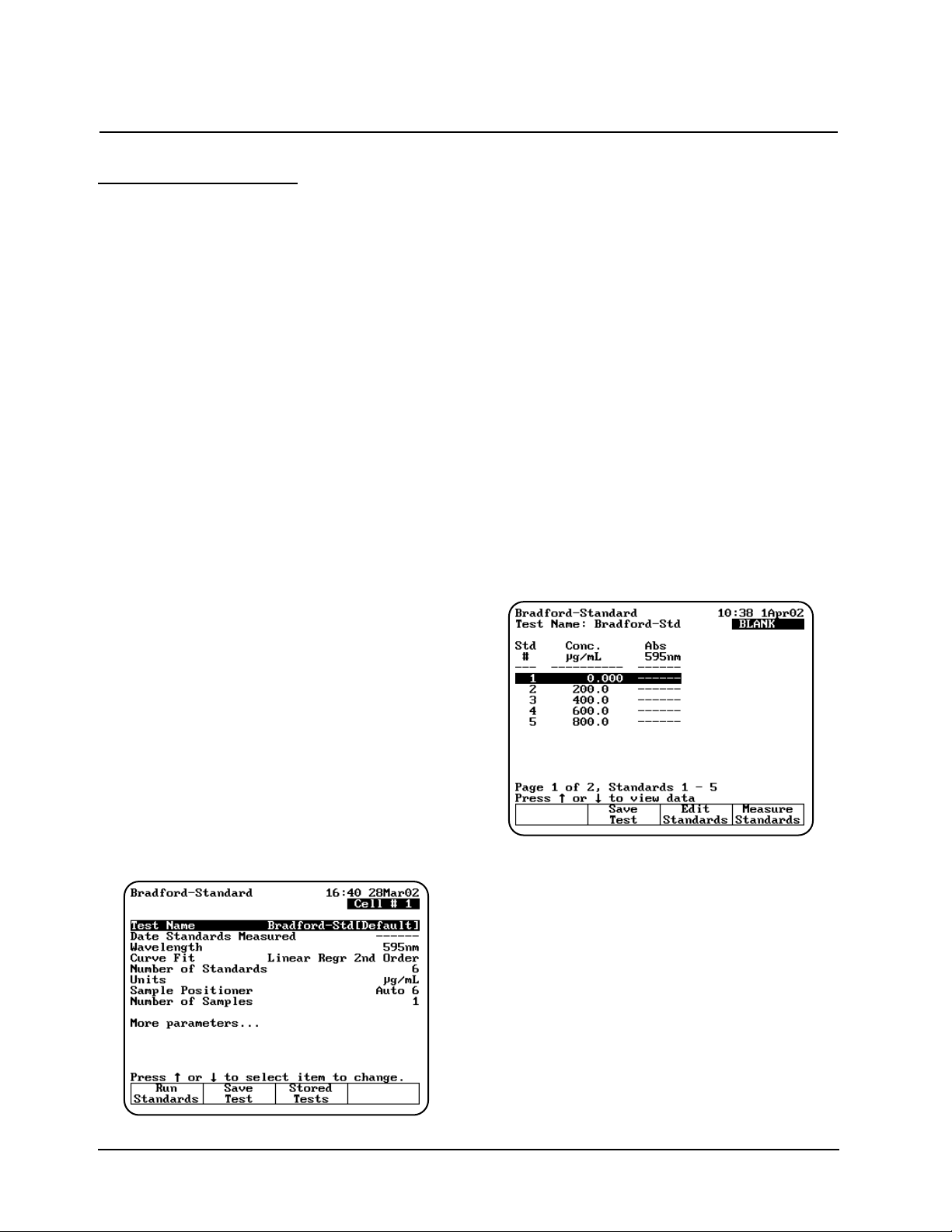
Setting up test parameters for a standard curve
1. With the Bradford-Standard setup screen
displayed, use the arrow keys to highlight the
name of the parameter you want to set. Set the
parameters for measuring the standards.
Refer to the list of parameters in Appendix B
for a description of the parameters and
Appendix C for the default values.
2. When the parameters are set, you can press
Save Test to save the test or Run Standards
to measure the blank and standards. The
Standard Measurement screen appears.
3. If you need to edit concentration values, use
the arrow keys to select the standard you want
to edit and press Edit Standards. From the
Edit Standards window you can edit, add or
delete one or all standards.
Measuring the standards for a standard curve
Measuring standards automatically (using Auto 6 or
Auto 3)
1. Place the blank and standards in the correct
cell positions.
2. When all the standards are correct, press
Measure Standards to set up and run the
standards. The instrument automatically
measures the blank first, then measures the
standards. When the instrument has measured
all the standards, the Standards screen
appears, showing the absorbance of each
Using “Biotests” Software
Thermo Electron Corporation 2-8
Page 29
standards, along with the slope, intercept and
correlation coefficient of the standard curve.
Measuring standards automatically (using Auto 6 or
Auto 3)
1. Place the blank and standards in the correct
cell positions.
2. When all the standards are correct, press
Measure Standards to set up and run the
standards.
3. Press Measure Blank to measure the blank. If
your instrument is equipped with a 6-Position
Cell Holder, it automatically moves to the B
position to measure the blank. When it
completes the measurement, it returns to its
previous cell position.
4. Press Measure Standards to measure the
standards. If your instrument is equipped with
a 6-Position Cell Holder, press the cell position
buttons on the keypad to re-position the cell
holder and measure the rest of the standards
manually.
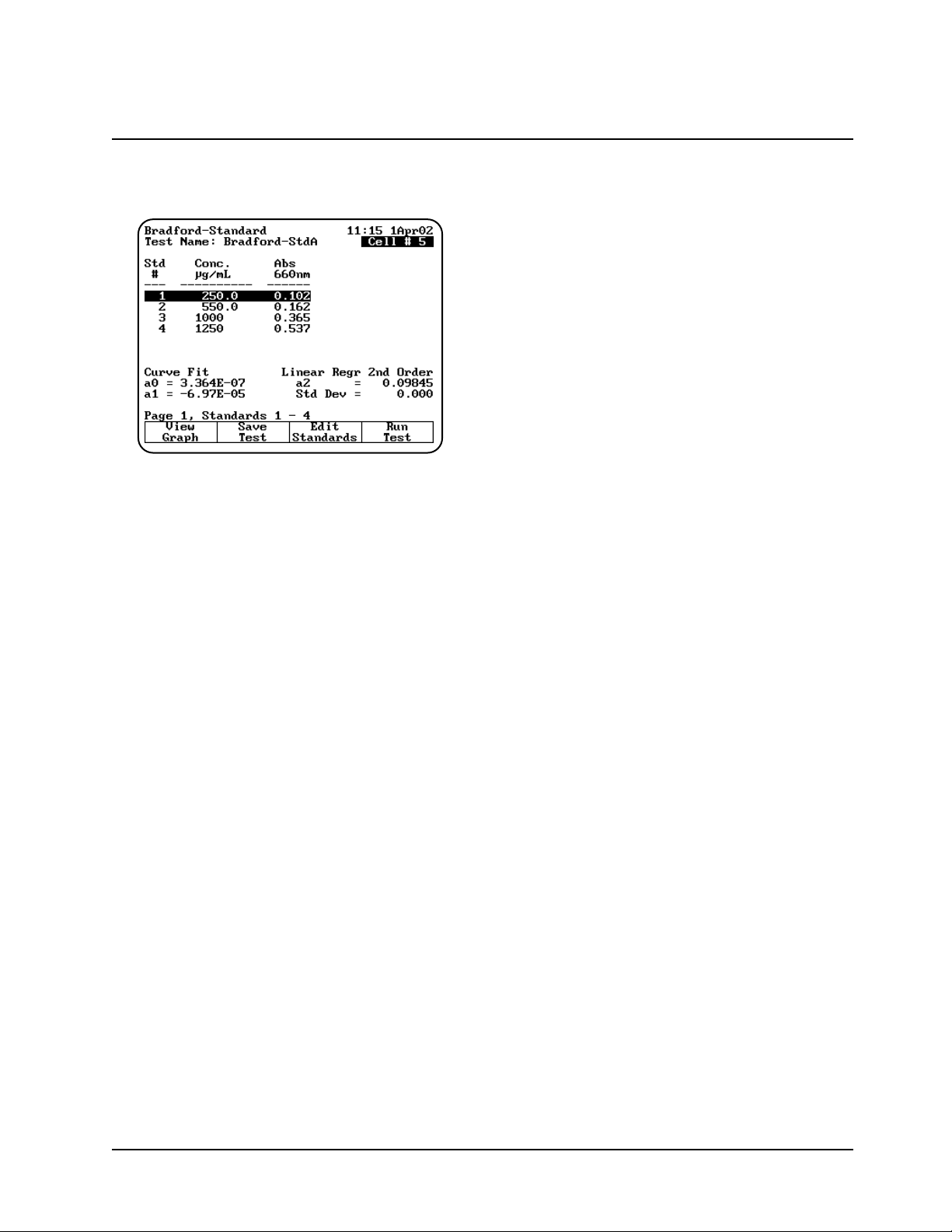
When the instrument has measured all the
standards, the Standards screen appears,
showing the absorbance of each standards,
along with the slope, intercept and correlation
coefficient of the standard curve.
You can use this screen to:
• Edit the standards (press Edit Standards)
• Display a graph of the standard curve data
(press View Graph)
• Save the standard curve (press Save Test)
• Measure your samples (press Run Test)
Measuring protein samples
Measuring unknowns automatically (using Auto 6
or Auto 3)
1. With the Standards screen displayed, place
the blank and unknowns in the correct cell
positions.
2. Press ENTER to start the measurements. The
instrument automatically measures the blank
first, then measures the unknowns and
displays the absorbance and concentration of
each unknown.
Measuring unknowns manually (using Manual 6 or
Single Cell Positioner)
1. With the Standards screen displayed, press
Run Test.
2. Place the blank and unknown in the correct cell
positions. If your instrument is equipped with a
6-Position Cell Holder, you can place up to five
samples in the cell holder.
3. Press Measure Blank to measure the blank. If
your instrument is equipped with a 6-Position
Cell Holder, it automatically moves to the B
position to measure the blank. When it
completes the measurement, it returns to its
previous cell position.
4. Press Measure Sample to start the
measurement. If your instrument is equipped
with a 6-Position Cell Holder, press the cell
position buttons on the keypad to re-position
the cell holder and measure the rest of the
unknowns manually.
Direct UV (280) and Direct UV (205)
The Direct UV methods determine protein
concentration based on absorbance at either 280
or 205nm. Refer to Appendix B for a description of
the parameters and Appendix C for the default
values.
To get started, move the arrow keys on the
BioMate tests screen to highlight Protein Tests
and press ENTER. Then the move the arrow keys
to highlight Direct UV (280) and press ENTER.
The Direct UV (280) parameter screen appears.
Note: The following screens show the
parameters for the Direct UV tests at
280nm. For the Direct UV test at 205nm,
the wavelength is set to 205nm.
Using “Biotests” Software
2-9 BioMate 3 Operator’s Manual
Page 30

Note: If Cell Correction is ON, you must run the
Setup Correction program before you can
access the Run Test or Measure
Samples keys.
Setting up test parameters
1. With the Direct UV (280) setup screen
displayed, use the arrow keys to highlight the
name of the parameter you want to set.
2. When the parameters are set, you can press
Save Test to save the test or to measure the
blank and unknowns.
Measuring the sample
Measuring unknowns automatically (using Auto 6
or Auto 3)
1. With the Direct UV (280) screen displayed,
place the blank and unknowns in the correct
cell positions.
2. Press ENTER to start the measurements. The
instrument automatically measures the blank
first, then measures the unknowns and
displays the absorbance and concentration of
each unknown.
Measuring unknowns manually (using Manual 6 or
Single Cell Positioner)
1. With the Direct UV (280) screen displayed,
press Run Test.
2. Place the blank and unknown in the correct cell
positions. If your instrument is equipped with a
6-Position Cell Holder, you can place up to five
samples in the cell holder.
3. Press Measure Blank to measure the blank. If
your instrument is equipped with a 6-Position
Cell Holder, it automatically moves to the B
position to measure the blank. When it
completes the measurement, it returns to its
previous cell position.
4. Press Measure Sample to start the
measurement. If your instrument is equipped
with a 6-Position Cell Holder, press the cell
position buttons on the keypad to re-position
the cell holder and measure the rest of the
unknowns manually.
Warburg-Christian
The Warburg-Christian analysis uses an
absorbance difference measurement at 280 and
260nm to determine the protein concentration of an
unknown. Refer to Appendix B for a description of
the parameters and Appendix C for the default
values.
To get started, move the arrow keys on the
BioMate tests screen to highlight Protein Tests
and press ENTER. Then the move the arrow keys
to highlight Warburg-Christian and press ENTER.
The Warburg-Christian parameter screen
appears.
Note: If Cell Correction is ON, you must run the
Setup Correction program before you can
access the Run Test or Measure
Samples keys.
Setting up test parameters
1. With the Warburg-Christian setup screen
displayed, use the arrow keys to highlight the
name of the parameter you want to set.
2. When the parameters are set, you can press
Save Test to save the test or Run Test to
measure the blank and unknowns.
Using “Biotests” Software
Thermo Electron Corporation 2-10
Page 31

Measuring the sample
Measuring unknowns automatically (using Manual
6 or Single Cell Positioner)
1. With the Warburg-Christian screen displayed,
place the blank and unknowns in the correct
cell positions.
2. Press ENTER to start the measurements. The
instrument automatically measures the blank
first, then measures the unknowns and
displays the absorbance and concentration of
each unknown.
Measuring unknowns manually (using Manual 6 or
Single Cell Positioner)
1. With the Warburg-Christian screen displayed,
press Run Test.
2. Place the blank and unknown in the correct cell
positions. If your instrument is equipped with a
6-Position Cell Holder, you can place up to five
samples in the cell holder.
3. Press Measure Blank to measure the blank. If
your instrument is equipped with a 6-Position
Cell Holder, it automatically moves to the B
position to measure the blank. When it
completes the measurement, it returns to its
previous cell position.
4. Press Measure Sample to start the
measurement. If your instrument is equipped
with a 6-Position Cell Holder, press the cell
position buttons on the keypad to re-position
the cell holder and measure the rest of the
unknowns manually.
5. When the instrument has measured all the
unknowns, it displays the absorbance and
concentration.
Cell Growth
The cell growth measurement uses absorbance at
600nm to indicate the progress of cell growth in a
sample. The instrument does not perform any
calculations or graphing for the data.
To get started, move the arrow keys on the
BioMate Tests screen to highlight Cell Growth
and press ENTER. The Cell Growth setup screen
appears.
Note: If Cell Correction is ON, you must run the
Setup Correction program before you can
access the Run Test or Measure
Samples keys.
Setting up test parameters
1. With the Cell Growth setup screen displayed,
use the arrow keys to highlight the name of the
parameter you want to set.
2. When the parameters are set, you can press
Save Test to save the test or Run Test to
measure the blank and unknowns.
Measuring the sample
Measuring unknowns automatically (using Auto 6
or Auto 3)
1. With the Cell Growth measurement screen
displayed, place the blank and unknowns in
the correct cell positions.
2. Press ENTER to start the measurements. The
instrument automatically measures the blank
first, then measures the unknowns and
displays the absorbance of each unknown
Measuring unknowns manually (using Manual 6 or
Single Cell Positioner)
1. With the Cell Growth measurement screen
displayed, press Run Test.
2. Place the blank and unknown in the correct cell
positions. If your instrument is equipped with a
6-Position Cell Holder, you can place up to five
samples in the cell holder.
3. Press Measure Blank to measure the blank. If
your instrument is equipped with a 6-Position
Cell Holder, it automatically moves to the B
position to measure the blank. When it
Using “Biotests” Software
2-11 BioMate 3 Operator’s Manual
Page 32

completes the measurement, it returns to its
previous cell position.
4. Press Measure Sample to start the
measurement. If your instrument is equipped
with a 6-Position Cell Holder, press the cell
position buttons on the keypad to re-position
the cell holder and measure the rest of the
unknowns manually.
5. When the instrument has measured all the
unknowns, it displays the absorbance and
concentration.
Oligo Calculator
The oligonucleotide calculator determines the
following data for a base sequence that you enter:
• Number of bases
• Percent GC content
• Molecular weight
• Absorptivity (ε)
• Conversion factor to convert nucleotide
absorbance to concentration
• Tm for oligos of up to 20 bases
• Tm for oligos of up to 40 bases for DNA-DNA,
DNA-RNA and RNA-RNA hybrids
Refer to Appendix B for a description of the
parameters and Appendix C for the default values.
To get started, move the arrow keys on the
BioMate Tests screen to highlight Oligo
Calculator and press ENTER. The Oligos screen
appears.
Using the oligo calculator
1. With the Oligos screen displayed, press Base
Sequence. The Base Sequence identification
screen appears.
2. Use the arrow keys to select the appropriate
character for the base you want to enter. Press
Add Base to add the base to the sequence.
3. When the base sequence is correct, press
Accept Sequence to accept it. The instrument
calculates and displays the results
4. To determine the theoretical Tm of the
sequence, press Tm Calc. The Tm calculation
screen appears.
5. Enter the % formamide and % mismatch (if
known) that will be used to calculate the Tm.
The calculated Tm values are shown on the
screen.
Using “Biotests” Software
Thermo Electron Corporation 2-12
Page 33

General information
Editing and Loading Saved Tests
When you save a test, it is stored in the Utility Test
Directory. Within this directory, these tests can be
loaded, deleted or locked/unlocked.
To load, delete or lock/unlock tests:
1. Press the UTILITY key on the keyboard. The
Utility screen appears.
2. Using the arrow keys, highlight Stored Tests
Directory and press ENTER. A list of all the
stored tests appears.
3. To load a test, use the arrow keys to highlight
the name of the test you want to recall and
press ENTER. The test will be loaded and the
parameters for the selected test appear on the
screen.
4. To lock or unlock a test, use the arrow keys to
highlight the name of the test you want to lock
or unlock and press Lock/Unlock. Enter the
password (found on page iii of this manual)
and press ENTER. The test is either locked or
unlocked.
5. To delete a test, use the arrow keys to highlight
the name of the test you want to delete. Press
ENTER. The test is deleted.
Specifying names for tests
When you save tests, you need to specify the name
you want to use for the file. The spectrophotometer
does not have a full keypad, so you need to select
the characters for the filename from a character
list.
1. After setting up the values for the test
parameters, press Save Test. The
Create Test Name screen appears.
You can use this screen to:
• Delete the name of a test
• Delete a character in the name of a test
• Add a character to the name of a test
• Accept the name of a test
2. Use the arrow keys to highlight the first
character you want to use for the name of your
test and press Add Character to add the
selected character to the name.
3. Continue selecting and adding characters until
you have selected all the characters for the
name.
4. Press Accept Name to accept the name and
return to the previous screen. The name of the
test appears at the top of the screen showing
the test parameters.
Specifying concentration units
When you run concentration tests, you need to
specify the units you want to use when reporting
concentrations. The spectrophotometer includes a
set of basic concentration units and you can also
enter custom units if you wish.
All programs in the spectrophotometer use the
same list of basic units:
• Concentration • mg/mL
• ppm • µg/L
• ppb • M/L
• g/L • mM/L
• mg/L • IU
In addition to these units, you can create your own
custom unit, using a character list like the one
described in Specifying names for tests. Once
Using “General Tests” Software
3-1 BioMate 3 Operator’s Manual
Page 34

you create a custom unit, it will appear in the list
that you use to select the units.
To select the units
1. Highlight the Units parameter on the screen
and press ENTER.
2. Use the arrow keys to highlight the unit you
want to select and press ENTER.
To create custom units
In addition to the basic concentration units, you can
create one other custom concentration unit and
add it to the list.
1. With the list of basic units displayed, use the
arrow keys to highlight [Unit] and press ENTER.
OR
Press Edit [Unit] on a test set-up screen for a
test with units.
The character list appears. You can use this
screen to:
• Delete the name of a unit
• Delete a character in the name of a unit
• Add a character to the name of a unit
• Accept the name of a unit
2. Use the arrow keys to highlight the first
character you want to use for the name of your
custom unit and press Add Character to add
the selected character to the name.
3. Continue selecting and adding characters until
you have selected all the characters for the
name.
4. Press Accept Name to accept the name and
return to the previous screen. The name of the
new custom unit appears on the list of basic
units.
Using the SmartStart feature
The SmartStart feature enables you to select the
test methods you use most frequently and have
them appear when you start up your instrument. If
your laboratory runs only a single test, you can use
the SmartStart feature to select it and it will appear
each time you start up your instrument. Similarly, if
you have a set of tests you run, you can use
SmartStart to select them so the list appears when
you start up the instrument.
Setting up a single-test SmartStart
1. Press the UTILITY key on the keypad to
display the Utility screen.
2. Highlight the Stored Tests Directory and
press ENTER. A list of all the tests on the
instrument appears on the screen.
3. Scroll down through the list until the
appropriate test is highlighted.
4. When the appropriate test is highlighted, press
Select Test to add the selected test to the
SmartStart menu. An arrow sign “>” will
indicate the test has been selected.
5. Press Load Test.
Using “General Tests” Software
Thermo Electron Corporation 3-2
Page 35

6. The parameter screen of the test you selected
will be displayed.
Note: At this point, you can power down the
instrument and then power it back up.
When it starts up again, the parameter
screen for the selected test will be
displayed.
Setting up a multiple-test SmartStart
1. Press the UTILITY key on the keypad to
display the Utility screen.
2. Highlight the Stored Tests Directory and
press ENTER. A list of all the tests on the
instrument appears on the screen.
3. Scroll down through the list until the first
appropriate test is highlighted.
4. Press Select Tests to add the selected test to
the SmartStart menu.
5. Continue scrolling through the list and adding
tests until you’ve made all the appropriate
selections.
6. Press ESC until you return to the Tests screen.
Note: At this point, you can power down the
instrument and then power it back up.
When it starts up again, the list of tests
you’ve selected will be displayed.
Running the cell correction program
Note: The Cell Correction program is not active
in the Main (Basic Absorbance/%T/Basic
Concentration) screen.
Note: The Cell Correction feature is active only
when the 6-Position Sample Holder is set
to either Auto 6 or Auto 3. The feature is
not active when the cell holder is set to 1-
Cell Platform or Manual 6, nor when the
Single Cell Holder is installed.
Every test setup screen provides access to the cell
correction program. Before running the cell
correction program:
• Clean the inside and outside of all the cells
to be matched.
• Fill the cells with distilled water (or other
blank solution), and place them in the
sample compartment (see “Selecting and
positioning glassware” in the preceding
section). Be sure to place the blank cuvette
in Cell “B” of the sample compartment.
TIP: If one cell has lower absorbance
than the others, make it the blank.
To run the Cell Correction program:
1. Press the TEST key on the keypad. When the
Test Types screen appears, highlight the test
you want to run and press ENTER.
2. Highlight Cell Correction and press ENTER.
The Cell Correction function is now activated, as
indicated by the word On across from Cell
Correction on the test setup screen.
Using “General Tests” Software
3-3 BioMate 3 Operator’s Manual
Page 36

Note: When Cell Correction is activated,
additional parameter lines are added to the
screen above the Cell Correction line. If
the Cell Correction line is no longer
visible on the screen, highlight More
parameters... and press ENTER.
3. Highlight Set Up Correction and press
ENTER. The Cell Correction screen appears.
4. Highlight Correction Mode and press ENTER
to set the mode to either:
• Scan - Cell Correction is run on a blank and
one sample cell for the range of
wavelengths you specify in Scanning
mode.
• Discrete nms - The Cell Correction
program is run on a blank and up to five
sample cells for up to 31 user-specified,
discrete wavelengths.
5. If you selected Scan mode in the preceding
step, press Run Corr. to start the Cell
Correction program. If you selected Discrete
nms mode, first specify the wavelengths using
the procedures which follow, and then the Cell
Correction program.
The Cell Correction program will measure the other
cells against the blank and will record, store and
date the measurements. From these
measurements the Cell Correction program
establishes the required correction factors, which
then are automatically applied during all
subsequent tests (if Cell Correction is activated).
Specifying wavelengths for Discrete nms mode:
1. Highlight Sample Positioner and press
ENTER to set this parameter to either Auto 3
(when using three, large cell holders) or Auto
6 (when using six, small cell holders).
2. Highlight Number of Matched Cuvettes and
press ENTER. Then use the keypad to specify
the number of cells you are matching. Press
ENTER.
3. Press Set nms to select the wavelengths for
which the Cell Correction program will be run. A
list of wavelengths appears.
Using “General Tests” Software
Thermo Electron Corporation 3-4
Page 37

Note: Cells should be matched at all analytical
wavelengths because matching at one
wavelength does not guarantee matching
at others.
4. Use the arrow keys to highlight the position
where you want to enter the first wavelength.
5. Press Add nm.
6. Enter the value for the wavelength and press
ENTER.
7. Continue until you have entered all the
wavelengths.
After all the wavelengths have been entered, press
Run Corr. to start the Cell Correction program. The
Cell Correction program will measure the other
cells against the blank and will record, store and
date the measurements. From these
measurements the Cell Correction program
establishes the required correction factors, which
then are automatically applied during all
subsequent tests (if Cell Correction is activated).
Taking measurements
The spectrophotometer lets you use different cell
holders and cell holder accessories to take
measurements. When you set up your test
parameters, you will select the type of measurement
you want to use and indicate how many samples you
have. You can choose from the following options:
• Auto 6 - You can take one blank measurement
and up to five sample measurements without
changing the samples in the cell holder. The
instrument automatically measures the blank (in
the blank position), then automatically advances
the cell holder to the appropriate position for the
next measurement. This option is available only
with the 6-Position Cell Holder.
• Auto 3 - You can take up to three
measurements without changing the samples in
the cell holder. The instrument automatically
measures the blank (in the blank position),
then automatically advances the cell holder to
the appropriate position for the next
measurement. This option is available only with
the 6-Position Cell Holder.
• Single Cell Platform - You place the blank in
the cell holder, measure it, place a sample in
the cell holder, then measure your sample.
This process is completely manual. In fact, the
cell position buttons on the keypad do not
function when you select Single Cell Platform
even if you have a 6-Position Cell Holder
installed in the sample compartment.
• Manual 6 - You can take up to six measurements
without changing the samples in the cell holder,
using the cell position buttons on the keypad to
advance the cell holder to the appropriate
position for the next measurement. You place
the blank in the blank position and your samples
in the other cell positions. Regardless of where
the cell holder is positioned, when you press
Measure Blank the cell holder automatically
goes to the blank position and measures the
blank. However, you can use the cell position
buttons to select a different position for the
measurement. This option is available only with
the 6-Position Cell Holder .
Note: When you have the 6-Position Cell Holder
installed, the instrument always considers
the material in the B position as a blank.
This means that even after measuring your
blank the first time, you can place
unknowns only in positions 1 through 5.
The two automatic measurements (Auto 6 and
Auto 3) are available only for instruments with the
6-Position Cell Holder. However, if you have one of
these models, you can also choose to take
measurements manually. Each test section later in
this chapter includes specific instructions on how to
take measurements automatically and manually.
Saving tests
When you power-down the instrument, the current
test is maintained by battery back-up. This means
that when you turn the instrument on again, the cell
holder alignment and values for all parameters will
be the same as they were when the instrument
was last used. When you load a test that has been
saved, the values for all parameters stored with
that test will replace the current values for the test
parameters.
As you create customized tests and collect data,
you will be saving tests for later use. The
spectrophotometer uses test files to contain the
values for all the parameters needed to run a test,
including the alignment of the cell holder and the
other parameters for the accessories installed.
Once you select the values for the parameters, you
Using “General Tests” Software
3-5 BioMate 3 Operator’s Manual
Page 38

can assign a test name and save the test. You can
then restore the test and run it without having to
set up the parameters again.
Basic Absorbance/%T measurements
The Absorbance/%Transmittance (%T) program
takes measurements and displays them as either
absorbance or %T. For each measurement taken,
the absorbance (or %T) appear on the screen, along
with the type of measurement, the date and time, the
wavelength and the cell position used for the
measurement. All the steps for taking measurements
in the two modes are the same - the only difference
will be the units used to display the results.
When you use the Basic Absorbance/%T program,
you can perform these tasks:
• Set the wavelength
• Measure a blank
• Measure unknowns
If you want to work with %T instead of absorbance,
simply press Change Mode until you see the %T
mode. You can switch from one mode to another
whenever you see the Change Mode function key.
Setting the wavelength
1. Press Set nm or any number key to set the
wavelength.
2. Enter the wavelength where you want the
measurements taken, then press Set nm again.
Measuring a blank
1. Place the blank in the cell holder. If your
instrument has a 6-Position Cell Holder, be
sure to place the blank in the B position.
2. If you want to enter an absorbance or
transmittance value for the blank, press a
number key and enter the concentration in the
Entry field.
3. Press Measure Blank to measure the blank.
When the instrument is finished measuring the
absorbance of the blank, the message disappears.
Measuring unknowns
1. If your instrument is equipped with the 6-Position
Cell Holder, place the unknown you want to
measure in one of the cell positions and press
the corresponding cell position button on the
keypad to move the cell holder to the measuring
position. The absorbance (ABS) or
%transmittance (%T) measurement appears on
the display.
If your instrument is equipped with the Single
Cell Holder Platform, remove the blank and
place the unknown in the cell holder. The
absorbance or %transmittance measurement
appears on the display.
Basic Concentration measurements
Measuring concentration is similar to measuring
absorbance or %T and you use the Change Mode
function key to switch to concentration measurements.
The spectrophotometer allows you to measure
concentration using either a factor or a standard to
convert absorbance readings to concentration units.
Using “General Tests” Software
Thermo Electron Corporation 3-6
Page 39

• When you use a factor, you need to specify the
factor and the concentration units.
• When you use a standard, you need to specify
the concentration of the standard and measure
its absorbance.
When you use the Basic Concentration program,
you can perform these tasks:
• Set the wavelength
• Measure a blank
• Measure a standard OR enter a factor
• Measure unknowns
The steps for taking measurements in the two
modes are similar - the only difference will be
whether you measure a standard or enter a factor.
Setting the wavelength & mode
1. Press Set nm or any number key to set the
wavelength.
2. Enter the wavelength where you want the
measurements taken, then press Set nm again.
3. Press Change Mode until the appropriate
measurement mode (Concentration with
Standard or Concentration with Factor)
appears.
Measuring a blank
1. Place the blank in the cell holder. If your
instrument has a 6-Position Cell Holder, be
sure to place the blank in the B position.
2. If you want to enter a concentration for the
blank, press a number key and enter the
concentration in the Entry field.
3. Press Measure Blank to measure the blank.
When the instrument is finished measuring the
absorbance of the blank, the message
disappears.
Measuring a standard
1. If necessary, press Change Mode to switch to
the Concentration with Standard mode.
2. If your instrument is equipped with the
6-Position Cell Holder, place the standard in
one of the cell positions and press the
corresponding cell position key on the keypad.
If your instrument is equipped with the Single
Cell Holder Platform, remove the blank and
place the standard in the cell holder.
3. Press Units/Standard to set the units and
measure the standard.
4. Enter Conc, use the number keys to enter the
concentration value of the standard and then
press ENTER.
5. Press Select Units, use the arrow keys to
highlight the entry in the Units field and then
press ENTER to select the units for the
concentration.
6. Press Measure Standard to measure the
standard. When the instrument is finished
measuring the absorbance of the standard, it
displays the absorbance and calculated factor.
Using “General Tests” Software
3-7 BioMate 3 Operator’s Manual
Page 40

Entering a factor
1. If necessary, press Change Mode to switch to
the Concentration with Factor mode.
2. Press Units/Factor to set the factor and select
the units.
3. Use the arrow keys to highlight the entry in the
Factor field and press Enter Factor to enter
the factor.
4. Use the number keys to enter the factor.
5. Press Enter Factor to accept the factor and
return to the screen displaying the factor and
units. The factor you just entered appears on
the display.
6. Press ESC to return to the Concentration
with Factor screen.
Measuring unknowns
1. If your instrument is equipped with the
6-Position Cell Holder, place the unknown you
want to measure in one of the cell positions
and press the corresponding cell position
button on the keypad to move the cell holder to
the measuring position. The measurement
appears on the display.
If your instrument is equipped with the Single
Cell Holder Platform, remove the blank and
place the unknown in the cell holder. The
measurement appears on the display.
Advanced A/%T/C - Absorbance &
%Transmittance measurements
When you use the Advanced A/%T/C program for
absorbance or %transmittance measurements, you
can perform these tasks:
• Select the measurement mode you want to use
(Absorbance or %Transmittance)
• Run Cell Correction program
• Recall a test OR set up your test parameters
• Measure a blank
• Measure unknowns
To get started, press the TEST key on the keypad.
When the Test Types screen appears, highlight
Advanced A/%T/C and press ENTER.
Recalling a test
1. With the Advanced A/%T/C screen displayed,
press Stored Tests. A list of stored tests
appears.
2. Use the arrow keys to highlight the name of
the test you want to recall and press ENTER.
The parameters for the selected test appear on
the screen.
Using “General Tests” Software
Thermo Electron Corporation 3-8
Page 41

From this screen, you can:
• Set up test parameters
• Run Cell Correction program
• Save a test
• View the list of stored tests
• Measure a blank and unknowns
Setting up test parameters
1. With the Advanced A/%T/C screen displayed,
use the arrow keys to highlight the name of the
parameter you want to set.
Some parameters appear only if you select
one of the concentration modes, while others
appear regardless of the measurement mode
you select. A complete list of the parameters
are located in Appendix B.
2. When the parameters are set, you can press
Save Test to save the test or Measure
Sample to measure a blank or unknowns.
Taking measurements
Taking measurements automatically (using Auto 6
or Auto 3)
1. With the Advanced A/%T/C screen displayed
and the parameters set, press Run Sample.
The Advanced A/%T/C measurement screen
appears.
2. Place the blank and the unknowns in the
correct cell positions.
3. Press Measure Sample to measure the
unknowns. The instrument automatically
measures the blank first, then measures the
unknowns and displays the sample
measurements on the screen.
Taking measurements manually (using Manual 6 or
Single Cell Platform)
1. With the Advanced A/%T/C screen displayed
and the parameters set, press Measure
Sample. The Advanced A/%T/C measurement
screen appears, prompting you to place your
samples in the cell holder.
2. Place the blank and unknowns in the cell
holder. If your instrument is equipped with a
6-Position Cell Holder, be sure to place the
blank in the B position. You can place up to
five samples in the cell holder.
3. Press Measure Blank to measure the blank. If
your instrument is equipped with a 6-Position
Cell Holder, it automatically moves to the B
position to measure the blank. When it
completes the measurement, it returns to its
previous cell position.
4. Press Measure Sample to measure the
unknowns. The sample measurement appears
on the screen. If your instrument is equipped
with a 6-Position Cell Holder, press the cell
position buttons on the keypad to reposition the
cell holder and measure the rest of the
unknowns manually.
Advanced A/%T/C - Concentration
measurements
When you use the Advanced A/%T/C program for
concentration measurements, you can perform
these tasks:
• Select the measurement mode you want to use
(concentration with one standard or
concentration with a factor)
• Recall a test OR set up your test parameters
• Measure a standard OR enter a factor (only if
you select either concentration with one
standard or concentration with a factor)
• Measure a blank and unknowns
To get started, press the TEST key on the keypad.
When the Test Types screen appears, highlight
Advanced A/%T/C and press ENTER.
Using “General Tests” Software
3-9 BioMate 3 Operator’s Manual
Page 42

Recalling a test
1. With the Advanced A/%T/C screen displayed,
press Stored Tests. A list of stored tests
appears.
2. Use the arrow keys to highlight the name of
the test you want to recall and press ENTER.
The parameters for the selected test appear on
the screen.
Setting up test parameters
1. With the Advanced A/%T/C screen displayed,
use the arrow keys to highlight the name of the
parameter you want to set.
Some parameters appear only if you select one
of the concentration modes, while others
appear regardless of the measurement mode
you select. A complete list of the parameters
are located in Appendix B.
2. When the parameters are set, you can press
Save Test to save the test or Run Test or Run
Standard to measure a standard.
Measuring a standard
Measuring a standard automatically (using Auto 6
or Auto 3)
1. With the Advanced A/%T/C screen displayed
and the Measurement Mode set to Conc/Std,
press Run Standard. The Measure Standard
screen appears.
2. Use the number keys to enter the
concentration value of the standard and press
ENTER.
3 Press Measure Standard.
4. Place the blank and standard in the correct cell
positions.
5. Press ENTER to measure the blank and the
standard. The instrument automatically
measures the blank first, then measures the
unknowns and displays the absorbance and
calculated factor.
Measuring a standard manually (using Manual 6 or
Single Cell Platform)
1. With the Advanced A/%T/C screen displayed
and the Measurement Mode set to Conc/Std,
press Run Standard. The Measure Standard
screen appears.
2. Use the number keys to enter the
concentration value of the standard and press
ENTER.
3. Place the blank and standard in the correct cell
positions.
Using “General Tests” Software
Thermo Electron Corporation 3-10
Page 43

4. Press Measure Blank to measure the blank. If
your instrument is equipped with a 6-Position
Cell Holder, it automatically moves to the B
position to measure the blank. When it
completes the measurement, it returns to its
previous cell position.
5. Press Measure Standard to measure the
standard. When the instrument is finished
measuring the absorbance of the standard, it
displays the absorbance and calculated factor.
Entering a factor
1. With the Advanced A/%T/C screen displayed
and the Measurement Mode set to
Conc/Factor, use the arrow keys to highlight
Factor.
2. If you need to change the factor, use the
number keys to enter the correct factor.
3. If you need to change the units, use the arrow
keys to highlight Units and select the correct
units.
Measuring unknowns
Measuring unknowns automatically (using Auto 6
or Auto 3)
1. With the Advanced A/%T/C screen displayed
and the Measurement Mode set to Conc/Std
or Conc/Factor, press Run Test. The
Advanced A/%T/C measurement screen
appears, prompting you to place your samples
in the cell holder.
2. Place the blank and unknowns in the correct
cell positions. Press ENTER. The instrument
automatically measures the blank first, then
measures the unknowns and displays the
sample measurements on the screen.
3. Press Measure Sample to measure additional
unknowns.
Measuring unknowns manually (using Manual 6 or
Single Cell Platform)
1. With the Advanced A/%T/C screen displayed
and the Measurement Mode set to Conc/Std
or Conc/Factor, press Run Test. The
Advanced A/%T/C measurement screen
appears.
2. Place the blank and unknown in the correct cell
position. If your instrument is equipped with a
6-Position Cell Holder, you can place up to five
samples in the cell holder.
3. Press Measure Blank to measure the blank. If
your instrument is equipped with a 6-Position
Cell Holder, it automatically moves to the B
position to measure the blank. When it
completes the measurement, it returns to its
previous cell position.
4. Press Measure Sample to start the
measurement. If your instrument is equipped
with a 6-Position Cell Holder, press the cell
position buttons on the keypad to reposition the
cell holder and measure the rest of the
unknowns manually.
S
tandard Curve
When you use the Standard Curve program, you
can perform these tasks:
• Recall a standard curve OR create a standard
curve (set up the parameters and then
measure the standards for the curve)
• Run the Cell Correction program (BioMate 3
UVscanning model only)
• Measure unknowns
• View the data - select between graphical and
tabular displays
• Edit a standard curve - change the number of
standards, select a different curve fit or delete
points from the curve
To get started, press the TEST key on the keypad.
When the Test Types screen appears, highlight
Standard Curve and press ENTER. The Standard
Curve screen appears.
Using “General Tests” Software
3-11 BioMate 3 Operator’s Manual
Page 44

Recalling a standard curve
1. Press Stored Tests to display a list of stored
tests.
2. Highlight the standard curve you want to recall.
3. Press ENTER to load the selected standard
curve.
Setting the parameters for a standard curve
1. Place the standards in the correct cell positions.
2. Set the parameters for measuring the
standards. Refer to the list of parameters in
Appendix B for a description of each.
• Enter the Test Name, Wavelength,
Reference Wavelength Correction and
Reference Wavelength.
• Select the Curve Fit, Units and Sample
Positioner.
• Set the Number of Standards and Number
of Samples.
• Enter the low and high limits.
• Select the settings for the Statistics and
AutoPrint functions.
• Run the Cell Correction program
Measuring the standards for a standard curve
Measuring standards automatically (using Auto 6 or
Auto 3)
1. Place the blank and standards in the correct
cell positions.
2. When all the parameters are correct, press
Run Standards to set up and run the
standards.
3. Enter the concentration value into the Entry
concentration field and press ENTER. When
you've entered all the concentration values, the
Standards screen appears.
4. Press Measure Standards to measure the
blank and standards. The instrument
automatically measures the blank first, then
measures the standards. When the instrument
has measured all the standards, the
Standards screen appears, showing the
absorbance of each standard, along with the
slope, intercept and correlation coefficient of
the standard curve.
Measuring standards manually (using Manual 6 or
Single Cell Platform)
1. Place the blank and standards in the correct
cell positions.
2. When all the parameters are correct, press
Run Standards to set up and run the
standards.
3. Enter the concentration value into the Entry
concentration field. Press ENTER
4. When you have entered all the concentration
values, the Standards screen appears.
5. Press Measure Blank to measure the blank. If
your instrument is equipped with a 6-Position
Cell Holder, it automatically moves to the B
position to measure the blank. When it
completes the measurement, it returns to its
previous cell position.
6. Press Measure Standards to measure the
standards. If your instrument is equipped with a
6-Position Cell Holder, press the cell position
buttons on the keypad to re-position the cell
Using “General Tests” Software
Thermo Electron Corporation 3-12
Page 45
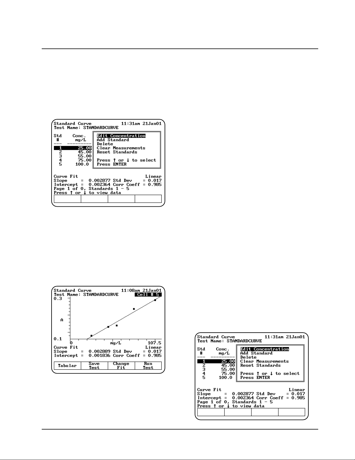
holder and measure the rest of the standards
manually.
When the instrument has measured all the
standards, the Standards screen appears,
showing the absorbance of each standard,
along with the slope, intercept and correlation
coefficient of the standard curve.
You can use this screen to:
• Edit the standards press (Edit Standards)
• Display a graph of the standard curve data
(press View Graph)
• Save the standard curve (press Save Test)
• Measure your samples (press Run Test)
If you want to switch between tabular and graphical
displays, press View Graph/Tabular.
Measuring unknowns
Measuring unknowns automatically (using Auto 6
or Auto 3)
1. With the Standards screen displayed, press
Run Test. The Samples screen appears.
2. Place the blank and unknowns in the correct
cell positions.
3. Press ENTER to measure. The instrument
automatically measures the blank first, then
measures the unknowns. When the instrument
has measured all the unknowns, the Standard
Curve screen appears, showing the
absorbance and concentration of each
unknown.
Measuring unknowns manually (using Manual 6 or
Single Cell Platform)
1. With the Standards screen displayed, press
Run Test. The Samples screen appears.
2. Place the blank and unknowns in the correct
cell positions.
3. Press Measure Blank to measure the blank. If
your instrument is equipped with a 6-Position
Cell Holder, it automatically moves to the B
position to measure the blank. When it
completes the measurement, it returns to its
previous cell position.
4. Press Measure Samples to measure the
unknowns. If your instrument is equipped with
a 6-Position Cell Holder, press the cell position
buttons on the keypad to re-position the cell
holder and measure the rest of the unknowns
manually. When the instrument has measured
all the unknowns, the Standards screen
appears, showing the absorbance and
concentration of each unknown.
Editing a standard curve
You may edit the concentration of any standard on
a standard curve. In addition, you may change the
number of standards, select a different curve fit or
delete points from the curve.
Using “General Tests” Software
3-13 BioMate 3 Operator’s Manual
Page 46
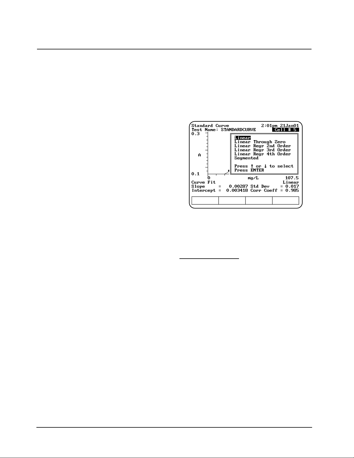
To edit the concentration of a standard
1. With the standard curve displayed on your
screen, use the arrow keys to highlight the
standard you want to edit. Press Edit
Standards.
2. With the Edit Concentration highlighted,
Press ENTER.
3. Press Edit Conc or a number key.
4. Enter the concentration value in the Entry
field.
5. When the concentration value is correct, press
ENTER to accept the value.
To add a standard
1. With the standard curve displayed on your
screen, press Edit Standards.
2. Use the arrow keys to highlight Add Standard.
3. Enter the concentration value of the additional
standard in the Entry field.
4. When the concentration value is correct, press
ENTER to accept the value.
5. Press Measure Standards to remeasure all
the standards.
To delete a standard
1. With the standard curve displayed on your
screen, use the arrow keys to highlight the
standard you want to delete. Press Edit
Standards.
2. Use the arrow keys to highlight Delete
Standard. Press ENTER to delete the
standard.
To clear measurements
1. With the standard curve displayed on your
screen, press Edit Standards.
2. Use the arrow keys to highlight Clear
Measurements and press ENTER. All the
absorbance measurements will be removed
from the screen.
To reset standards
1. With the standard curve displayed on your
screen, press Reset Standards and press
ENTER.
2. Use the arrow keys to highlight Reset
Standards and press ENTER. All the
standards and measurements will be removed.
To select a different curve fit for a standard curve
Note: To change the curve fit for a standard
curve, you must display the standard curve
as a graph, not as a table.
1. With the standard curve you want to edit
displayed as a graph on your screen, press
Change Fit.
2. Use the arrow keys to highlight the curve fit
you want to use for the standard curve and
press ENTER. The instrument applies the
selected curve fit to the data and displays the
new graph.
Absorbance Ratio
When you use the Absorbance Ratio program, you
can perform these tasks:
• Recall a test OR set up your test parameters
• Run the Cell Correction program
• Measure a blank
• Measure unknowns
To get started, press the TEST key on the keypad.
When the Test Types screen appears, highlight
Absorbance Ratio and press ENTER.
Using “General Tests” Software
Thermo Electron Corporation 3-14
Page 47

Recalling a test
1. With the Absorbance Ratio screen displayed,
press Stored Tests. A list of stored tests
appears.
2. Use the arrow keys to highlight the name of
the test you want to recall and press ENTER.
The parameters for the selected test appear on
the screen.
From this screen, you can:
• Set up test parameters
• Run the Cell Correction program
• Save a test
• View the list of stored tests
• Measure a blank
• Measure unknowns
Setting up test parameters
1. With the Absorbance Ratio screen displayed,
use the arrow keys to highlight the name of the
parameter you want to set.
2. When the parameters are set, you can press
Save Test to save the test or Run Test to
measure a blank or unknowns.
Measuring unknowns
Measuring unknowns automatically (using Auto 6
or Auto 3)
1. Place the blank and unknowns in the correct
cell positions.
2. Press ENTER to start the measurement. The
instrument automatically measures the blank
first, then measures the unknowns and
displays the sample measurements on the
screen.
Measuring unknowns manually (using Manual 6 or
Single Cell Platform)
1. With the Absorbance Ratio screen displayed,
press Run Test.
2. Place the blank and unknown in the correct cell
position. If your instrument is equipped with a
6-Position Cell Holder, you can place up to five
samples in the cell holder.
3. Press Measure Blank to measure the blank. If
your instrument is equipped with a 6-Position
Cell Holder, it automatically moves to the B
Using “General Tests” Software
3-15 BioMate 3 Operator’s Manual
Page 48

position to measure the blank. When it
completes the measurement, it returns to its
previous cell position.
4. Press Measure Sample to start the measurement.
If your instrument is equipped with a 6-Position
Cell Holder, press the cell position buttons on
the keypad to re-position the cell holder and
measure the rest of the unknowns manually.
Absorbance Difference
When you use the Absorbance Difference program,
you can perform these tasks:
• Recall a test OR set up your test parameters
• Run the Cell Correction program
• Measure a blank
• Measure unknowns
To get started, press the TEST key on the keypad.
When the Test Types screen appears, highlight
Absorbance Difference and press ENTER.
Recalling a test
1. With the Absorbance Difference screen
displayed, press Stored Tests. A list of stored
tests appears.
2. Use the arrow keys to highlight the name of
the test you want to recall and press ENTER.
The parameters for the selected test appear on
the screen.
From this screen, you can:
• Set up test parameters
• Set up Cell Correction program
• Save a test
• View the list of stored tests
• Measure a blank
• Measure unknowns
Setting up test parameters
1. With the Absorbance Difference screen
displayed, use the arrow keys to highlight the
name of the parameter you want to set.
2. When the parameters are set, you can press
Save Test to save the test or Run Test to
measure a blank or unknowns.
Measuring unknowns
Measuring unknowns automatically (using Auto 6
or Auto 3)
1. With the Absorbance Difference screen
displayed, press Run Test.
2. Place the blank and unknowns in the correct
cell positions.
3. Press ENTER to start the measurement. The
instrument automatically measures the blank
first, then measures the unknowns and
displays the sample measurements on the
screen.
Measuring unknowns manually (using Manual 6 or
Single Cell Platform)
1. With the Absorbance Difference screen
displayed, press Run Test.
2. Place the blank and unknown in the correct cell
position. If your instrument is equipped with a
6-Position Cell Holder, you can place up to five
samples in the cell holder.
3. Press Measure Blank to measure the blank. If
your instrument is equipped with a 6-Position
Cell Holder, it automatically moves to the B
Using “General Tests” Software
Thermo Electron Corporation 3-16
Page 49

position to measure the blank. When it
completes the measurement, it returns to its
previous cell position.
4. Press Measure Sample to start the
measurement. If your instrument is equipped
with a 6-Position Cell Holder, press the cell
position buttons on the keypad to re-position
the cell holder and measure the rest of the
unknowns manually.
Kinetics
When you use the Kinetics program, you can
perform these tasks:
• Recall a test OR set up your test parameters
• Run the Cell Correction program
• Measure a blank
• Measure an unknown
• Recalculate reaction rates
• Modify the scale of the plot
When you use the Kinetics program, you can
choose to work with either graphical data or with
tabular data. You can perform the same functions
regardless of the type of display you select.
However, the location of function keys varies
depending on the type of display you choose.
Note: The Kinetics program allows you to
measure only one unknown at a time.
Note: The Kinetics program allows you to collect
up to 400 data points per run. When you
set up your test parameters, be sure to
select the interval time and total run time
accordingly.
To get started, press the TEST key on the keypad.
When the Test Types screen appears, highlight
Kinetics and press ENTER.
Recalling a test
1. With the Kinetics screen displayed, press
Stored Tests. A list of stored tests appears.
2. Use the arrow keys to highlight the name of
the test you want to recall and press ENTER.
The parameters for the selected test appear on
the screen.
From this screen, you can:
• Set up test parameters
• Run the Cell Correction program
• Save a test
• View the list of stored tests
• Measure a blank
• Measure unknowns
• Set up your analog recorder
Setting up test parameters
1. With the Kinetics screen displayed, use the
arrow keys to highlight the name of the
parameter you want to set.
2. When the parameters are set, you can press
Save Test to save the test or Run Test to
measure a blank or an unknown.
Measuring unknowns
Note: If your instrument is equipped with a 6-
position cell holder, be sure to place the
blank in position B and the unknown in cell
position #1. The instrument always uses
cell position #1 to scan the unknown.
3-17 BioMate 3 Operator’s Manual
Using “General Tests” Software
Page 50

1. With the Kinetics test parameters displayed on
the screen, press Run Test.
2. If you have a 6-position cell holder, place the
blank in position B and the unknown in position
#1. Press Measure Sample to measure the
blank and the unknown. When the instrument
completes the measurement, the kinetics data
and rate appear on the screen.
3. If you have 1-position cell holder, press
Measure Blank to measure the blank, then
insert your unknown and press Measure
Sample. When the instrument completes the
measurement, the kinetics data and rate
appear on the screen.
If you want to switch between tabular and graphical
displays, press Graph/Tabular.
When you have a graphical display, you can press
Edit Graph, then press Cursor to move the cursor
line from one position to another on the plot. As the
cursor moves the rate and result values indicate
the values for the point on the plot where the
cursor is located.
Rescaling & recalculating graphical kinetics
results
Within the Kinetics program, you can view and
manipulate your results either in graphical form or
in tabular form. When your results are displayed on
the screen, you can modify the range (start and
stop time) and the instrument automatically
recalculates the reaction rate.
When you are working with graphical kinetics
results, you need to press Edit Graph before you
can rescale and recalculate.
You can modify the scale of your kinetics data plot
in two ways - automatically or manually. When you
select Auto Scale, the instrument automatically
scales the X- and Y-axes so all the data appears on
the plot. When you select Manual Scale, you select
specific minimum and maximum values for the Xand Y-axes. Whenever you modify the scale, the
instrument also automatically recalculates and
displays the new reaction rate and result.
When the edit screen appears, you can:
• Use the Auto Scale function to change the
scale, display the new graph and recalculate
the results
• Use the Manual Scale function to change the
scale, display the new graph and recalculate
the results
• Use the cursor to select new minimum or
maximum values for the X-axis and recalculate
the results.
To use the Auto Scale function
1. With your kinetics data displayed on the Edit
Graph screen, press Auto Scale. The
instrument automatically adjusts the minimum
and maximum values for the X- and Y-axes so
all the data appears on the plot. The instrument
also recalculates the results, using all the data,
and displays it on the screen.
To use the Manual Scale function
1. With your kinetics data displayed on the edit
screen, press Manual Scale. The manual
scale options appear.
Using “General Tests” Software
Thermo Electron Corporation 3-18
Page 51

2. Use the number keys to enter the appropriate
minimum or maximum value for the X- or Yaxis, then press the appropriate function key
(Min Y, Max Y, Min X, Max X) to accept it. The
instrument redraws the plot using the minimum
and maximum value you have entered and
displays the recalculated rate and result.
3. Continue until you have entered all the values
you want to change.
To use the cursor
1. With your kinetics data displayed on the edit
screen, press Cursor. The cursor options
appear.
2. Press Cursor ←←or Cursor →→to position the
cursor line on the appropriate point on the
graph. The instrument displays the data for the
selected point.
3. When the cursor line is in the correct position,
press Set Min X or Set Max X to accept the
selected point. The instrument redraws the plot
using the minimum and maximum value you
have selected and displays the recalculated
rate and result.
Rescaling & recalculating tabular kinetics
results
When you are working with tabular kinetics results,
you need to press Edit Data before you can
rescale and recalculate.
After collecting your kinetics data, you can use all
the data for the rate calculation or you can select
specific start and end times. Whenever you modify
the start and end times or select all the data, the
instrument automatically recalculates and displays
the new reaction rate and result.
When the edit screen appears, you can:
• Use all the data to recalculate the results
• Select specific start and end times for the rate
calculation and recalculate the results.
To use all the data to calculate the reaction rate
1. With your table of kinetics data displayed on the
edit screen, press Use all data. The instrument
calculates the rate and displays it on the screen.
To select specific start and end times for the
rate calculation
1. With your table of kinetics data displayed on
the edit screen, use the arrow keys on the
keypad to move the highlight symbol (→→) to the
appropriate data point in the table.
2. Press Start Time or End Time. The instrument
displays the recalculated rate and result.
3-19 BioMate 3 Operator’s Manual
Using “General Tests” Software
Page 52

Survey Scan/
Scanning
The Survey Scan program allows you to scan a
wavelength range. When you use the Survey Scan
program, you can perform these tasks:
• Recall a test OR set up your test parameters
• Run the Cell Correction program
• Collect a baseline scan
• Scan an unknown
• View scan data
• Change the scale of the data plot
• Determine 3-point net measurements
• Calculate the area under a curve
• Label peaks and valleys
Note: The Survey Scan/Scanning program allows
you to measure only one unknown at a
time. Auto 6, Auto 3 and Manual 6 are not
available for scanned measurements.
Note: If you want to set a baseline expiration
time, press UTILITIES, then use the arrow
keys to highlight Baseline Expiration.
Press ENTER and set the desired time.
To get started, press the TEST key on the keypad.
When the Test Types screen appears, highlight
Survey Scan or Scanning and press ENTER.
Recalling a test
1. With the Survey Scan/Scanning screen
displayed, press Stored Tests. A list of stored
tests appears.
2. Use the arrow keys to highlight the name of
the test you want to recall and press ENTER.
The parameters for the selected test appear on
the screen.
From this screen, you can:
• Set up test parameters
• Set up Cell Correction program
• Save a test
• View the list of stored tests
• Collect a baseline
• Scan unknowns
Setting up test parameters
1. With the Survey Scan/Scanning screen
displayed, use the arrow keys to highlight the
name of the parameter you want to set.
2. When the parameters are set, you can press
Save Test to save the test or Run Test to
measure a blank or an unknown.
Collecting a baseline scan
Note: If your instrument is equipped with a
6-Position Cell Holder, be sure to place the
blank in the B position. The instrument always
uses the B position to collect the baseline.
1. With the Survey Scan/Scanning test
parameters displayed, press Run Test.
2. Place the blank in the B position.
3. Press Measure Blank to collect the baseline.
When the instrument is finished measuring the
blank, the message disappears.
Note: If you want to switch between tabular and
graphical displays, press Graph/Tabular.
Using “General Tests” Software
Thermo Electron Corporation 3-20
Page 53

Scanning an unknown
Note: If your instrument is equipped with a
6-Position Cell Holder, be sure to place the
unknown in cell position #1. The instrument
always uses cell position #1 to scan the
unknown.
1. With the Survey Scan test parameters displayed
on the screen, press Run Test.
2. If your instrument is equipped with a 6-Position
Cell Holder, be sure to place the unknown in
cell position #1.
3. Press Measure Sample to measure the
unknown.
Note: If you want to switch between tabular and
graphical displays, press Graph/Tabular.
Note: You may need to use the up and down
arrow keys to view all the data for the scan.
Viewing & manipulating scan data
Within the Survey Scan/Scanning program, you
can view and manipulate your results either in
graphical form or in tabular form.
When you are working with graphical scan data,
you need to press Edit Graph before you can
perform other functions on the scan data.
When the edit graph screen appears, you can:
• Rescale the graph
• Perform mathematical operations on the graph
Rescaling graphical scan data
You can modify the scale of your scan data plot in
two ways - automatically or manually. When you
select Auto Scale, the instrument automatically
scales the X- and Y-axes so all the data appears
on the plot. When you select Manual Scale, you
select specific minimum and maximum values for
the X- and Y-axes. Whenever you modify the scale,
the instrument also automatically recalculates and
displays the new data plot.
Press Edit Scale to modify the scale. When the
edit scale screen appears, you can:
• Use the cursor to identify specific points along
the X-axis, change the scale and display the
new graph
• Use the Manual Scale function to change the
scale and display the new graph
• Use the Auto Scale function to change the
scale and display the new graph
Using “General Tests” Software
3-21 BioMate 3 Operator’s Manuall
Page 54

To use the cursor
1. With your scan data displayed on the edit scale
screen, press Cursor. The cursor option
appears
2. Press Cursor →→or Cursor ←←.to position the
cursor line on the appropriate point on the
graph. The instrument displays the data for the
selected point.
3. When the cursor line is in the correct position,
press Set Min X or Set Max X to accept the
selected point. The instrument redraws the plot
using the minimum and maximum value you
have selected and displays the new graph.
To use the Manual Scale function
1. With your scan data displayed on the edit scale
screen, press Manual. The manual scale
options appear.
2. To set the minimum or maximum value for the
X- or Y-axis, press Min Y, Max Y, Min X or
Max X. A screen appears prompting you to
enter the appropriate value.
3. Use the number keys to enter the correct
value, then press the appropriate function key
(Min Y, Max Y, Min X, Max X) to accept it. The
instrument redraws the plot using the minimum
and maximum values you have entered.
To use the Auto Scale function
1. With your scan data displayed on the edit scale
screen, press Auto Scale. The instrument
automatically adjusts the minimum and
maximum values for the X- and Y-axes so all
the data appears on the plot.
Performing calculations on the scan data
You can modify your graph by performing
calculations on the data. From the Edit Graph
screen press Math. When the Math screen
appears, you can:
• Determine 3-point net values
• Calculate the area under a curve
• Label peaks and valleys
Determining 3-point net measurements
1. With your scan data displayed on the edit
graph screen, press Math. The Math
Calculation screen appears.
2. Press 3-Pt Net to enter the 3-point Net
Measurement screen. A screen showing the
cursor options and three cursor lines
(designated for the left, center and right
wavelengths) appears.
Using “General Tests” Software
Thermo Electron Corporation 3-22
Page 55

3. Use Cursor →→and Cursor ←←to position the
left cursor line to the desired wavelength value.
The instrument calculates the 3-point net
absorbance for the selected wavelengths.
4. Continue selecting the other wavelengths by
pressing Next Cursor to activate the center
and right cursor lines. Select the wavelengths
by positioning the cursor with the Cursor
←←
and Cursor
→→
keys. Repeat until all three
wavelengths have been selected.
5. Press Enter Factor to access the set factor
box. Enter the desired factor and press
ENTER. The instrument calculates the value
for the 3-point net absorbance for the selected
wavelengths, multiplied by the selected factor.
Calculating the area under a curve
1. With your scan data displayed on the Edit
Graph screen, press Math. The Math
Calculation screen appears.
2. Press Area. The Area Under the Curve
Measurement screen appears.
3. Use Cursor
→→
and Cursor
←←
to position the
left cursor line to the desired wavelength value.
The instrument calculates the area under the
curve for the selected wavelengths.
4. Continue selecting the other wavelengths by
pressing Next Cursor to activate the next
cursor line. Select the wavelength by
positioning the cursor with the Cursor
→→
and
Cursor
←←
keys.
5. Press Set Options to access the set options
window.
6. Use the up and down arrows to highlight
Factor. Enter the desired factor and press
ENTER.
7. Use the up and down arrow to highlight
Calculation baseline. Press ENTER to toggle
between Zero and Tangent.
8. Press ESC to return to the area under a curve
screen. The instrument calculates the area
under a curve for the selected wavelengths,
factor and calculation method.
Labeling peaks and valleys
1. With your scan displayed on the edit graph
screen, press Math. The Math Calculation
screen appears.
2. Press Peaks & Valleys. The Label Peaks and
Valleys window appears.
3. Use the arrow keys to select the type of labels
you want displayed and press ENTER. The
instrument labels the selected items on your
scan data plot.
Using “General Tests” Software
3-23 BioMate 3 Operator’s Manual
Page 56
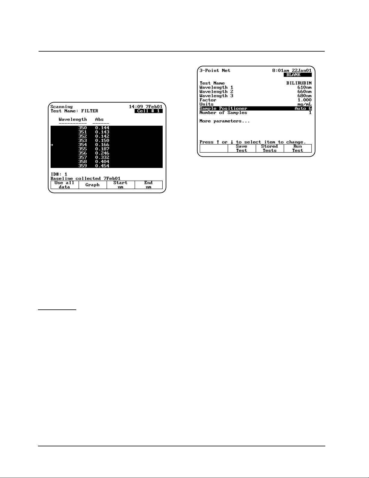
Viewing & rescaling tabular scan data
When you are working with tabular scan data, you
need to press Edit Data before you can perform
other functions on the scan data.
To use all the scan data
1. With your table of scan data displayed on the
edit screen, press Use all data.
To select specific start and end wavelengths
1. With your table of scan data displayed on the
edit screen, use the arrow keys on the keypad
to move the highlight symbol (→→) to the
appropriate data point in the table.
2. Press Start nm or End nm. The instrument
highlights the selected data points.
You can press Graph to display the plot using
the highlighted data points.
3-Point Net
When you use the 3-Point Net program, you can
perform these tasks:
• Recall a test OR set up your test parameters
• Run the Cell Correction program
• Measure a blank
• Measure unknowns
To get started, press the TEST key on the keypad.
When the Test Types screen appears, highlight
3-Point Net and press ENTER.
Recalling a test
1. With the 3-Point Net screen displayed, press
Stored Tests. A list of stored tests appears.
2. Use the arrow keys to highlight the name of
the test you want to recall and press ENTER.
The parameters for the selected test appear on
the screen.
From this screen, you can:
• Set up test parameters
• Run the Cell Correction program
• Save a test
• View the list of stored tests
• Measure a blank
• Measure unknowns
Setting up test parameters
1. With the 3-Point Net screen displayed, use the
arrow keys to highlight the name of the
parameter you want to set.
2. When the parameters are set, you can press
Save Test to save the test or Run Test to
measure a blank or unknowns.
Taking measurements
Taking measurements automatically (Auto 6 or
Auto 3)
1. With the 3-Point Net screen displayed and the
parameters set, press Run Test. The
3-Point Net measurement screen appears.
Using “General Tests” Software
Thermo Electron Corporation 3-24
Page 57

2. Place the blank and the unknowns in the
correct cell positions.
3. Press ENTER to start the measurements. The
instrument automatically measures the blank
first, then measures the unknowns and
displays the sample measurements on the
screen.
Taking measurements manually (using Manual 6 or
Single Cell Platform)
1. With the 3-Point Net screen displayed and the
parameters set, press Run Test. The 3-Point
Net measurement screen appears.
2. Place the blank and unknowns in the cell
holder. If your instrument is equipped with a 6Position Cell Holder, be sure to place the blank
in the B position. You can place up to five
samples in the cell holder.
3. Press Measure Blank to measure the blank. If
your instrument is equipped with a 6-Position
Cell Holder, it automatically moves to the B
position to measure the blank. When it
completes the measurement, it returns to its
previous cell position.
4. Press Measure Sample to measure the
unknowns. The sample measurement appears
on the screen. If your instrument is equipped
with a 6-Position Cell Holder, press the cell
position buttons on the keypad to reposition the
cell holder and measure the rest of the
unknowns manually.
Multiple Wavelengths
When you use the Multiple Wavelengths program,
you can perform these tasks:
• Recall a test OR set up your test parameters
• Run the Cell Correction program
• Add or delete wavelengths and factors
• Measure a blank
• Measure unknowns
To get started, press the TEST key on the keypad.
When the Test Types screen appears, highlight
Multiple Wavelengths and press ENTER.
Recalling a test
1. With the Multiple Wavelengths screen
displayed, press Stored Tests. A list of stored
tests appears.
2. Use the arrow keys to highlight the name of
the test you want to recall and press ENTER.
The parameters for the selected test appear on
the screen.
From this screen, you can:
• Set up test parameters
• Run the Cell Correction program
3-25 BioMate 3 Operator’s Manual
Using “General Tests” Software
Page 58

• Save a test
• View the list of stored tests
• Measure a blank
• Measure unknowns
Setting up test parameters
1. With the Multiple Wavelengths screen
displayed, use the arrow keys to highlight the
name of the parameter you want to set.
*Refer to the procedures below for specific
instructions on adding or deleting wavelengths
and factors.
2. If you have previously selected the
wavelengths you wish to measure, you can
press Save Test to save the test or Run Test
to measure a blank or unknowns.
3. If you have not selected the wavelengths, you
can add wavelengths and factors as shown
below.
Adding wavelengths & factors
Note: You can enter factors only when the
measurement mode is set to
Concentration/Factor.
1. With the Multiple Wavelengths screen
displayed, press Set nms. The wavelength
screen appears, listing the wavelengths and
factors specified for the measurements.
2. Use the arrow keys to highlight the position
where you want to enter the first wavelength
and factor pair.
3. Press Add nm.
4. Enter the values for the wavelength and factor
and press ENTER.
5. When the values are correct, press Add nm.
6. Continue until you have entered all the
wavelengths and factors.
Deleting wavelengths & factors
1. With the Multiple Wavelengths screen
displayed, use the arrow keys to highlight Set
nms. The wavelength screen appears, listing
the wavelengths and factors specified for the
measurements.
Note: If no wavelength values have been
entered, the wavelength and factor
columns will be empty.
2. Use the arrow keys to highlight the first
wavelength and factor pair you want to delete.
3. Press Delete nm.
Taking measurements
Taking measurements automatically (Auto 6 or
Auto 3)
1. The Multiple Wavelength acquisition can be
accessed from either the Set nms screen
shown above or from the Multiple Wavelength
set up screen. Press Run Test. The Multiple
Wavelength measurement screen appears.
2. Place the blank and the unknowns in the
correct cell positions.
3. Press ENTER to start the measurement. The
instrument automatically measures the blank
first, then measures the unknowns and
displays the sample measurements on the
screen.
Using “General Tests” Software
Thermo Electron Corporation 3-26
Page 59

Taking measurements manually (using Manual 6 or
Single Cell Platform)
1. With the Multiple Wavelength screen
displayed and the parameters set, press Run
Test. The Multiple Wavelength measurement
screen appears.
2. Place the blank and unknowns in the cell
holder. If your instrument is equipped with a
6-Position Cell Holder, be sure to place the
blank in the B position. You can place up to
five samples in the cell holder.
3. Press Measure Blank to measure the blank. If
your instrument is equipped with a 6-Position
Cell Holder, it automatically moves to the B
position to measure the blank. When it
completes the measurement, it returns to its
previous cell position.
4. With the list of wavelengths (and factors)
displayed, press Measure Samples to measure
the unknowns. The instrument measures the
absorbance at each wavelength and displays it
on the screen. If you have set the
measurement mode to Concentration/Factor,
the instrument also displays the calculated
concentration at each wavelength.If your
instrument is equipped with a 6-Position Cell
Holder, press the cell position buttons on the
keypad to reposition the cell holder and
measure the rest of the unknowns manually.
Using “General Tests” Software
3-27 BioMate 3 Operator’s Manual
Page 60

Using “General Tests” Software
Thermo Electron Corporation 3-28
Page 61

Overview
The Performance Validation program allows you to
run tests to check the performance of your
instrument. Available tests include:
• Wavelength Accuracy - Internal
• Wavelength Accuracy - Standards
• Photometric Accuracy
• Noise Measurement
• Stray Light
• Internal Printer Test
• RS232C Test
Running the appropriate performance validation
tests regularly and maintaining a log of your results
helps document the reliability of the instrument and
indicates potential performance issues.
Note: If you have a printer installed and turned
on, the instrument automatically prints out
the test results for each performance
validation test that you run. You can also
press the PRINT key to print another copy
of the results.
Accessing the Performance Validation
tests
1. Press the TESTS key on the keypad. The Test
Types screen appears.
2. Highlight Performance Validation and press
ENTER. The Performance Validation screen
appears.
Troubleshooting checklist
If a Performance Validation test fails, follow the
instructions below to help you diagnose common
problems that may cause a test to fail. If a test
continues to fail after you have tried all the
recommendations in the list, follow the
troubleshooting list for the test being run (included
with the description of each test).
• Make sure you are following the instructions for
the test properly.
• Make sure filters and standards are clean.
• Make sure the sample compartment door is
closed while the test is running.
• Make sure the sample compartment is clear of
any obstructions.
• Make sure the 6-Position Cell Holder is
installed properly; run the test once with the
sample compartment door open to verify that
the 6-Position Cell Holder is moving smoothly.
• Turn the instrument power OFF, then ON;
verify that no problems are indicated by the
power-on diagnostics.
• Make sure the lamp is ON.
• Make sure the lamp compartment is clear of
any obstructions.
Wavelength Accuracy - Internal
This test locates the peaks and displays the
expected and measured wavelengths for the peaks
at the following wavelengths:
• UV-Vis instruments - measures wavelength
accuracy for the xenon lamp at 229, 529 and
883nm.
Using the Performance Validation Program
4-1 BioMate 3 Operator’s Manual
WARNING
Do not open the lamp compartment unless the
instrument power is OFF.
Do not turn the instrument power ON unless the
lamp compartment is closed!
Page 62
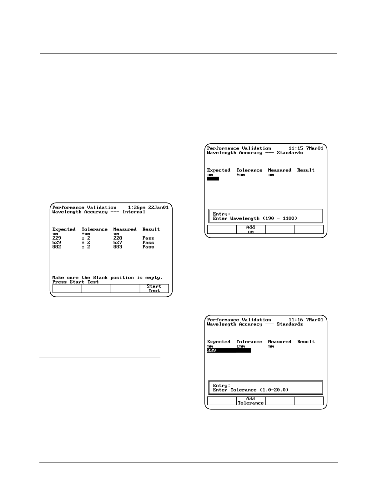
When running the internal standard test, remember
that:
• The wavelengths are preset and cannot be
changed.
• The xenon lamp has a preset tolerance of
±2.0nm.
• The cell holder should be empty.
1. With the Performance Validation screen
displayed, use the arrow keys to highlight
Wavelength Accuracy - Internal.
2. Press ENTER. The Wavelength Accuracy Internal screen appears.
3. Press Start Test to run the test. The results of
the test appear on the screen, indicating pass
or fail for each wavelength.
If the test fails, follow these guidelines:
• Repeat the test several times to verify that the
test is failing consistently.
• Contact technical support for more
troubleshooting advice.
Wavelength Accuracy - Standards
This test measures the absorbance of a filter
standard at up to five wavelengths and compares
the results with specified tolerances. The
wavelengths and tolerances are preset, but you
should change them to the values on the certificate
of calibration included with your standards.
Note: Only the middle wavelength of the
SPECTRONIC Standards wavelength
standard is certified. The wavelength accuracy
test passes or fails based on this wavelength
alone. The other two wavelengths may be
used for long-term repeatability testing. The
initial target values may be determined by
running the wavelength accuracy test once,
and taking note of the values reported in the
Measured Wavelength column.
1. With the Performance Validation screen
displayed, use the arrow keys to highlight
Wavelength Accuracy - Standards and press
ENTER. The Wavelength Accuracy Standards screen appears.
Adding wavelengths
1. If you need to add a wavelength, press Add
nm and enter the wavelength value in the
Entry field.
2. When the value is correct, press Add nm
again to add the wavelength to the list. The
screen changes to prompt you to enter the
tolerance for the wavelength you just entered.
3. Enter the tolerance value in the Entry field.
4. When the value is correct, press Add
Tolerance to add the tolerance.
Using the Performance Validation Program
Thermo Electron Corporation 4-2
Page 63

Deleting wavelengths
1. If you want to delete a wavelength, use the
arrow keys to highlight the appropriate
wavelength.
2. When the appropriate wavelength is
highlighted, press Delete nm to confirm that
you want to delete the wavelength.
Running the test
1. With the Wavelength Accuracy - Standards
screen displayed, make sure that the
wavelengths and tolerances are set correctly.
2. Press Start Test to run the test. The results of
the test appear on the screen, indicating pass
or fail for each wavelength.
If the test fails, follow these guidelines:
• Repeat the test several times to verify that the
test is failing consistently.
• Make sure the target value you entered for the
calibrated wavelength is the same as the value
printed on the SPECTRONIC Standards
certificate.
• Make sure the tolerance value you entered for
the calibrated wavelength is the same as the
value given in the SPECTRONIC Standards
User's Manual.
Photometric Accuracy
This test measures the absorbance (or
%transmittance) of a set of standards and
compares the results with specified tolerances. The
absorbances and tolerances are preset, but you
should change them to the values on the report of
calibration included with your standards.
Note: You can display the tolerances for this test
in either absorbance or %transmittance.
1. With the Performance Validation screen
displayed, use the arrow keys to highlight
Photometric Accuracy.
2. Press ENTER. The Photometric Accuracy
screen appears.
Selecting the mode
1. To switch between absorbance and
%transmittance, press Change to %T (or
Change to ABS) until the appropriate mode
appears.
Adding standards
You will need to set three values whenever you
add a standard - the wavelength, the absorbance
(or %transmittance) and the tolerance value.
1. If you need to add a standard, press Add Std
and enter the wavelength value in the Entry
field.
2. When the wavelength value is correct, press
Add Std again to add the wavelength to the
list. The screen changes to prompt you to enter
the absorbance (or %transmittance) for the
wavelength you just entered.
3. Enter enter the tolerance value in the Entry
field.
4. Press Start Test or Press ESC to save test.
Using the Performance Validation Program
4-3 BioMate 3 Operator’s Manual
Page 64

Deleting standards
1. If you need to delete a standard, use the arrow
keys to highlight the appropriate standard.
2. When the appropriate standard is highlighted,
press Delete Std to confirm that you want to
delete the standard.
Running the test
1. With the Photometric Accuracy screen
displayed, make sure that the wavelengths,
absorbance (or %transmittance) values and
tolerances are set correctly.
2. Press Start Test to run the test. The results of
the test appear on the screen, indicating pass
or fail for each wavelength.
If the test fails, follow these guidelines:
• Repeat the test several times to verify that the
test is failing consistently.
• Make sure you follow the guidelines provided
with the standard reference materials.
• Contact technical support for more
troubleshooting advice.
Noise Measurement
This test measures the amount of noise (peak-topeak) at specified wavelengths:
• UV-Vis instruments - measures noise at 230
and 340nm
All parameters are preset and cannot be changed.
When running the noise test, remember that:
• The wavelengths are preset and cannot be
changed.
• The Blank position should be empty.
• Position #1 should be used for the 2A filter in a
6-cell holder only (if measured).
1. With the Performance Validation screen
displayed, use the arrow keys to highlight
Noise Measurement.
2. Press ENTER. The Noise Measurement
screen appears.
Using the Performance Validation Program
Thermo Electron Corporation 4-4
Page 65

3. Make sure that the Blank position is empty and
insert the 2A filter in position #1 if you are
measuring at 2A.
4. Press Start Test to run the test. The results of
the test appear on the screen, indicating pass
or fail for each wavelength.
If the test fails, follow these guidelines:
• Repeat the test several times to verify that the
test is failing consistently.
• Make sure the instrument is warmed up for at
least 30 minutes, standby mode = OFF.
• Make sure the instrument is plugged into a
stable power supply.
• Contact technical support for more
troubleshooting advice.
Stray Light
This test measures the amount of stray light at
selected wavelengths and compares them to
specified tolerances. The wavelengths are preset
and cannot be changed. You should change the
tolerances for the desired wavelengths. Running the
stray light test takes approximately thirty seconds.
When running the stray light test, remember that:
• You will need the SPECTRONIC Standards
Stray Radiant Energy filters or equivalent.
• Position B should be empty.
• Position #1 should be used for SRE 220.
• Position #2 should be used for SRE 340.
• Position #3 should be used for SRE 400.
You may use other filters, but they must have
<
–
0.1%T at the wavelength of interest.
1. With the Performance Validation screen
displayed, use the arrow keys to highlight
Stray Light.
2. Press ENTER. The Stray Light screen
appears.
Running the test
1. With the Stray Light screen displayed, make
sure that the wavelengths and tolerances are
set correctly.
2. Press Start Test to run the test. The results of
the test appear on the screen, indicating pass
or fail for each wavelength.
If the test fails, follow these guidelines:
• Repeat the test several times to verify that the
test is failing consistently.
• Make sure all the filters being used are
SPECTRONIC Standards Stray light filters, or
exact equivalents.
• Contact technical support for more
troubleshooting advice.
Internal Printer Test
The Internal Printer test allows you to verify that
the internal printer is functional. To run the test, you
will need to have the internal printer installed.
Running the internal printer test takes no more
than 20 seconds after you press Stop.
1. Verify that the internal printer is installed
properly and is selected. If necessary, press the
UTILITY key, then select the internal printer.
2. With the Performance Validation screen
displayed, use the arrow keys to highlight
Internal Printer Test.
Using the Performance Validation Program
4-5 BioMate 3 Operator’s Manual
Page 66

3. Press ENTER. The Internal Printer Test
screen appears.
4. Press Start Test to run the test. The test print
routine appears on the printer.
While the test is running, you can press Stop
Test to stop it.
If the test fails, follow these guidelines:
• Make sure that the internal printer is the
selected printer device on the Utilities screen.
• Make sure that the internal printer is installed
correctly. (Return to the main screen and press
ENTER. If the paper does not move, the printer
may not be installed correctly.)
• Make sure that the thermal paper is threaded
with the thermal side toward the printer head
(the outside surface of the roll is the thermal
surface).
• Contact technical support for more
troubleshooting advice.
RS232C Test
The RS232C test allows you to verify that the
RS232C port is functional. To run the test, you will
need to have the RS232 Test Plug (336035)
attached to the RS232C port on the back panel of
the instrument. Running the RS232C test takes
approximately five minutes.
1. Verify that the RS232 Test Plug is securely
attached to the RS232C port on the back panel
of the instrument.
2. With the Performance Validation screen
displayed, use the arrow keys to highlight
RS232C Test.
3. Press ENTER. The RS232C Test screen
appears.
4. Press Start Test to run the test. When the test
is complete, the message "RS232 OK" or
RS232 Failed" appears on the screen.
While the test is running, you can press Stop
Test to stop it.
If the test fails, follow these guidelines:
• Make sure that the test plug is installed
correctly and is not loose or damaged.
• Contact technical support for more
troubleshooting advice.
Using the Performance Validation Program
Thermo Electron Corporation 4-6
Page 67

General information
The spectrophotometer supports a variety of
sample-handling accessories. This section
describes how to connect and use the following
types of accessories:
• Cell holders and cell holder accessories
• Internal printer
• External computer
Cell holders & cell holder accessories
If the spectrophotometer includes a 6-Position Cell
Holder, you can install a single-position cell
platform. However, if your spectrophotometer is a
Single-Position Cell Platform model, you cannot
upgrade it to accommodate a 6-Position Cell
Holder.
The following table lists the cell holders and cell
holder accessories available for the
spectrophotometer.
Connecting & Using Accessories
5-1 BioMate 3 Operator’s Manual
Catalog # Description
335916 Single Cell Holder Platform -with single cuvette holder installed. Included in 335900 and
335902 models.
336014 Test Tube Holder - Accommodates test tubes up to 25mm in diameter and up to 102mm
tall, C.O.D. reagent vials and Hach vials (24mm diameter and 60mm tall); fits on 335927
6-Position Cell Holder (holds three) or 335916 Single Cell Holder Platform (holds one).
335917 Adjustable Filter Holder - Accommodates glass or plastic filters up to 50mm long x
80mm tall x 10mm thick; minimum thickness of 1mm; fits on 335927 6-Position Cell
Holder (holds three) or 335916 Single Cell Holder Platform (holds one).
335428 Filter Holder - Accommodates filters/lenses up to 50mm long x 80mm tall x 1-8mm thick;
fits on 335927 6-Position Cell Holder (holds three) or 335916 Single Cell Holder Platform
(holds one).
335079 Thermal Block - Controls the temperature of one 10mm pathlength square cuvette within
the range of 20 to 100ºC; fits on 335927 6-Position Cell Holder (holds three) or 335916
Single Cell Holder Platform (holds one); requires external water bath and 335921
Accessory Door for routing circulating water.
336028 Single Cell Holder - Accommodates 10mm test tubes, 10mm square cuvettes, short
pathlength cuvettes with spacers, and 10mm ultra-microcell; fits on 335927 6-Position Cell
Holder or 335916 Single Cell Holder Platform.
335911 Cylindrical Longpath Cell Holder - Accommodates a cylindrical cell with 10-50mm
pathlength, 22-25mm diameter; fits on 335927 6-Position Cell Holder (holds three) or
335916 Single Cell Holder Platform (holds one).
335912 Rectangular Longpath Cell Holder - Accommodates a rectangular cell with 10-50mm
pathlength, 12.5mm wide; fits on 335927 6-Position Cell Holder (holds three) or 335916
Single Cell Holder Platform (holds one).
336012 Cylindrical Longpath Cell Holder - Accommodates one cylindrical cell with 10-100mm
pathlength, 22-25mm diameter; requires 335916 Single Cell Holder Platform.
335112 Rectangular Longpath Cell Holder - Accommodates one rectangular cell with 10-100mm
pathlength, 12.5mm wide; requires 335916 Single Cell Holder Platform.
335989 Internal Printer Assembly - Includes 1 roll of paper.
335982* Peristaltic Pump - Includes set of Norprene pump tubing; used with 335171 Optical
Glass flowcell or 335172 Quartz flowcell and 335921 Accessory Door Kit. 115V, 50/60Hz.
335982-02 Same as 335982 except with Europlug 230 VAC
335982-04 Same as 335982 except with UK plug 230 VAC
Page 68

Changing cell holders
If you want to use longpath cells (cylindrical or
rectangular), use test tubes, measure solid filters or
regulate cell temperature via an external water
circulator, you must install the appropriate cell
holders. You can easily remove the 6-Position Cell
Holder installed in the instrument and install other
accessory cell holders.
*Whenever you change from one type of cell
holder to another, you must measure a blank. This
ensures that the instrument can detect which type
of cell holder is installed.
Removing the 6-Position Cell Holder
1. Open the sample compartment and let the
sample compartment door rest on its hinge.
2. With one hand, loosen the captive thumbscrew.
3. With the other hand, pull straight up on the 6-
Position Cell Holder and lift it out of the sample
compartment.
Installing the 6-Position Cell Holder
1. Open the sample compartment and let the
sample compartment door rest on its hinge.
2. With one hand, carefully lower the 6-Position
Cell Holder straight down into the sample
compartment.
3. With the other hand, tighten the captive
thumbscrew.
4. Close the sample compartment.
5. Take a blank measurement to ensure that the
instrument detects that you have installed the
6-Position Cell Holder.
Installing the Single-Position Cell Holder
1. With the sample compartment open, place the
Single-Position Cell Platform as shown in
Figure 5.
2. Tighten the screws securely.
Note: If the cell holder is not aligned correctly, you
will not be able to tighten the screws.
3. Take a blank Measurement to ensure that the
instrument detects that you have installed the
Single-Cell Platform.
Installing accessory cell holders
1. Make sure that you have the correct cell holder
installed. If you want to use 100mm longpath
cells, you must install the Single-Position Cell
Holder.
2. Install the desired accessory cell holders by
tightening the screw on each cell holder.
Note: You can install only three each of some
accessory cell holders. Make sure to place
them in positions B, 2 and 4.
Connecting & Using Accessories
Thermo Electron Corporation 5-2
Catalog # Description
335921 Accessory Door Kit - Includes spout and four ports for circulating water around water-
jacketed cells, or for waste outlet for flowcell systems.
335977 Funnel Flowcell - 10mm pathlength, optical glass, for measurements between 335-
1100nm; fits on 335916 Single Cell Holder Platform (holds one).
335927 6-Position Cell Holder - platform with six (6) 336028 single cell holders installed.
333150 SPECTRONIC Standards
336029 Spacers - 5mm, set of 2, for use with 5mm short pathlength cuvettes in any square cell
holder.
336030 Spacers - 8mm, set of 2, for use with 2mm or 1mm short pathlength cuvettes in any
square cell holder.
335942 Serial interface cable to connect the spectrophotometer to an IBM-compatible PC.
331751 Ultra-microcell - 10 µl fill volume, 1mm pathlength, 40mm tall, quartz.
331752 Ultra-microcell - 70 µl fill volume, 10mm pathlength, 50mm tall, quartz. Requires 335916
Single Cell Holder Platform (holds one) for optimal performance
Note: If you want to use 100mm longpath cells, you must install the Single-Position Cell Platform.
Page 69

Internal printer
Installing the internal printer
||
|
WARNING
|
||
|
Turn off the instrument and disconnect the
|
|
power cord from the outlet before installing the
|
|
internal printer.
|
1. Loosen the captive screw (#1, Figure 6) on the
lamp door by rotating it counterclockwise about
¼ turn.
2. Open the lamp door.
3. Use a pen or screwdriver to lift the tabs holding
the door to the hinge (#2 & #3, Figure 6).
4. Slide the door off the hinge.
5. Remove the printer (already installed on the
printer door) from its packing.
6. Unclip the connector wires on the door hinge.
7. Lower the hinge so it is out of the way.
8. Connect the wires (#4, Figure 6) and press into
place with a small screwdriver. There is only
one way that the connectors will fit. Each
connector has a slight D shape. Make sure the
side of the connector with the shiny metal
contacts (see Figure 6) and faces away from
the printer and towards the plastic door.
9. Use the clip on the hinge to secure the wires.
10. Install the printer door by sliding it back onto
the hinge (#3, Figure 6).
11. Close the lamp door.
12. Tighten the captive screw (#1, Figure 6) on the
printer door to hold it securely in place.
13. Load the paper into the printer (see instructions
in Setting up the instrument).
Loading the paper in the internal printer
For instructions on loading the paper in the internal
printer, see Setting up the instrument.
External computers
To connect an external computer, make sure that
the pin-outs on the connectors are set according to
the illustration below.
To connect an external computer, connect the
computer cable to the 9-pin RS232C port on the
back of the instrument (#2, Figure 2). Be sure to
use a DB9 pin (female) to DB9 pin (female)
interface cable (335942).
Contact technical support for more information
about using an external computer with the
spectrophotometer.
5-3 BioMate 3 Operator’s Manual
Connecting & Using Accessories
Protocol to use with external device:
Baud rate 19,200
Data bits: 8
Parity: Off
Stop Bit: 1
Page 70

Thermo Electron Corporation 5-4
Connecting & Using Accessories
Page 71

The spectrophotometer is durable and reliable, so
routine maintenance is minimal. This section
includes complete instructions for:
• Routine care, cleaning and maintenance of the
instrument and cells
• Changing the fuse and voltage setting
This section also includes a list of replacement
parts and accessories.
||
|
WARNING
|
||
|
Operating the instrument with the cover off
|
|
exposes the operator to potentially dangerous
|
|
voltages and ultraviolet (UV) radiation.
|
|
Therefore, the distributor recommends that
|
|
only authorized service representatives perform
|
|
procedures requiring removal of the instrument
|
|
cover and replacement of electrical components.
|
|
To protect both yourself and the instrument, be
|
|
sure to contact an authorized service
|
|
representative to perform any service procedure
|
|
you do not feel comfortable performing.
|
Routine care
Routine care for the spectrophotometer does not
require a lot of time. To help minimize maintenance
time and to increase the life and performance of
your instrument, please follow these guidelines:
• To prevent dust from accumulating on and in
the instrument, always replace the dust cover
when the instrument is not turned on. The dust
cover, supplied with the instrument, is resistant
to most aqueous solutions.
• Do not use or store the instrument in a
corrosive environment.
• Gently wipe the outside of the instrument with
a soft cloth to remove any dust or spills. Water,
isopropyl alcohol and other common laboratory
cleaning agents may be used if necessary.
• Always clean up spills to prevent or minimize
damage to the instrument. If concentrated
acids or bases, or any hydrocarbon materials,
are spilled on the instrument, be sure to clean
up the affected area immediately.
• Use water, alcohol or other common laboratory
cleaning agents to clean the keyboard. It is
recommended that you clean spills off the
keyboard as soon as they occur.
Cleaning
Cleaning and maintenance of cells
Cleaning of cells both inside and out is important
not only because any contaminating material may
absorb light, but also because material within the
cell may react chemically with subsequent reagents
or standards introduced into the cell. Cleaning
methods depend to some extent on the nature of
the contaminating material. Sodium (or ammonium)
hydroxide and dilute hydrochloric acid may be used
to remove some acidic and basic contaminants,
respectively. Clorox (undiluted or 1:1) is very
effective in removing proteinaceous and bacterial
contaminants. You may also use Cell Cleaning
Solution (332260-169) to clean your cells.
Finally, soaking in chromic acid will remove most
contaminants, but the acid should be handled, and
disposed of, with care. Because of the exothermic
reaction of the acid and water, any heat generated
should be quickly dissipated to avoid altering the
pathlength of the cell. Cells should not be placed in
hot chromic acid.
Note: To prepare chromic acid cleaning solution,
slowly add (with stirring) 800mL of
concentrated sulfuric acid to 458mL of
distilled water containing 92 g of sodium
dichromate (Na2Cr2O7•2H2O). This cleaning
solution should be red-brown. Discard,
using proper disposal methods, when
green tinge appears.
Performing Maintenance Procedures
6-1 BioMate 3 Operator’s Manual
WARNING
Handle and dispose of chromic acid with care!
Page 72

Cells with scratches in the optical path should be
discarded because scratches will cause anomalous
absorbance readings. Cells should be protected
during cleaning and never thrown into a bath with
glassware where they might get scratched, or
placed in a wire rack that might scratch them. The
outside of the cells may be wiped with a soft, lintfree tissue, and should be kept free of fingerprints.
Micro flowcells can be kept clean by:
• Flushing well with a solvent after use
• Aspirating dilute acid, base, non-filming
detergent or Clorox through the cell in short
bursts
• Storing with distilled water in the cell
Cleaning the windows of the sample
compartment
Follow these guidelines to clean the windows of
the sample compartment:
• Do not use acetone to clean the windows
of the sample compartment. Instead, use a
non-abrasive laboratory cleaning solution (Cell
Cleaning Solution, 332260-169), distilled water
or alcohol.
• Use the liquid and a soft, lint-free cloth to clean
the windows. Do not apply too much pressure
or the surface of the windows may be
damaged. Be sure to remove all fingerprints.
Changing the fuse
The fuse is located in the power entry module
located at the center of the back panel of the
instrument (Figure 2).
• 120VAC, 2.5A, Slo-Blo
• 240VAC, 1.25A, Slo-Blo (2 required)
See Replacement parts on page 5-3 for a list of
replacement part numbers.
||
|
WARNING
|
||
|
The instrument fuse must be replaced with the
|
|
same type and rating fuse.
|
||
|
WARNING
|
||
|
If the fuse fails repeatedly, it may indicate a
|
|
serious problem with the instrument. Contact
|
|
your service representative as soon as possible.
|
1. Turn off and unplug the instrument.
2. Position the instrument so you can access the
power entry module on the back of the
instrument.
3. Remove the power cord.
4. Insert a flat-blade screwdriver into the notch
(Figure 8) on the fuse cover and pry off the
cover.
5. Use a flat-blade screwdriver to remove the fuse
holder (Figure 9).
6. Unsnap both fuses (Figure 10) to remove them.
7. Insert the new fuses, pushing them in so they
snap into place.
8. Replace the fuse cover.
9. Replace the power cord.
10. Plug the instrument back in the appropriate
outlet and turn on the power.
Note: If the fuse blows again, contact your
distributor or service at the number(s)
listed on the back cover.
Performing Maintenance Procedures
Thermo Electron Corporation 6-2
Page 73

Catalog # Description
335916 Single Cell Platform - with single cuvette holder installed.
336028 Single Cell Holder - Accommodates 10mm test tubes, 10mm square
cuvettes, short pathlength cuvettes with spacers, and 10mm ultra-microcell;
fits on 335927 6-Position Cell Holder or 335916 Single Cell Holder Platform.
335927 6-Position Cell Holder - with six (6) 336028 single cell holders installed.
335989 Internal Printer Assembly.
333152 Sensitized Paper - (100 sheets) for SPECTRONIC Standards.
335965 Replacement Dust Cover.
335954 Printer Paper - Package of 5 rolls.
335904-10001 BioMate 3 Operator’s Manual.
335901-10020 Service Manual, includes printed service manual and CD ROM.
335901-10040 BioMate 3 Service Manual, includes CD ROM only.
335971 Replacement silicone tubing for 335982 Peristaltic pump, 5mm OD,
1.5mm ID, 25 foot roll.
Replacement parts
Performing Maintenance Procedures
6-3 BioMate 3 Operator’s Manual
Page 74

Performing Maintenance Procedures
Thermo Electron Corporation 6-4
Page 75

Appendix A - Specifications
A-1 BioMate 3 Operator’s Manual
Specifications
Table 1 Specifications for BioMate 3 spectrophotometers
1
BioMate 3
Spectral Bandwidth 5nm
Optical System Split beam, grating-based, dual detectors
Lamp Source; Lifetime Xenon; 5 years typical
Wavelength
Range 190 - 1100nm
Accuracy ± 1.0nm
Repeatability ± 0.5nm
Display 320 x 240 pixel LCD, 3.8" x 2.8"
Photometric
Range 0.3 - 125%T; -0.1 - 3.0A; 0 - 9999C
Readout Absorbance, Transmittance, Concentration
Accuracy
3
0.5% or 0.005A, whichever is greater, up to 2A
Noise ≤ 1mA at 0A; ≤ 2mA at 2A, peak-to-peak at 340nm
Drift ≤ 1mA/hour
Stray Light
4
≤ 0.1%T at 220 and 340nm
Standard Interface Bi-directional RS232C
Standard Cell Holder 1-position and automatic 6-position cell holder
Keyboard Membrane keypad
Software DNA ratio/concentration with or without scanning
Direct protein at 280nm
Protein standard curves
Cell growth
Oligo calculator - absorptivity, molecular weight, factor and theoretical T
m
Absorbance/Transmittance/Concentration
Absorbance Ratio
Absorbance Difference
Standard Curve
Kinetics
Survey Scan
Performance Validation
Multiple Wavelength
3 Point Net
Test Storage Up to 40 sets of test parameters
Languages Software and Printout: English, French, German, Spanish, Italian
(user selectable)
Printer (optional) 40-column internal graphics
Power Requirements Selected automatically; 100 - 240 Volts
Page 76
Appendix A - Specifications
Thermo Electron Corporation A-2
Table 2 Environmental and electrical
requirements (meets the IEC 1010-1
international safety standard)
Line voltages
100 - 240 VAC ±10%
50 - 60 Hz
80 VA max
Operating environment
The instrument meets the specifications on the
previous page under the following conditions
after a 30-minute warm-up period.
Ambient temperature: 5° to 35° C
(41° F to 95° F)
Relative humidity - 20% - 80% RH
Storage environment
-20° C to 70° C (-4° F to 158° F) Relative
humidity not to exceed 0.040 pounds
moisture per pound of dry air. Allow
instrument to adjust to room temperature for
24 hours after taking it out of storage.
Temperature should be maintained at ±4° F.
Relative humidity should be maintained to ±5%.
Altitude
From below sea level to 2000 meters
(6562 feet)
For indoor use only
Installation Category II
Pollution Degree 2
BioMate 3
Dimensions 330W x 410D x 235H mm (13" x 16" x 9")
Weight 8.6 Kg (19lb)
Warranty 1 year
1
These specifications are valid only when the required environmental conditions (see below) are met.
2
When working in the range of 800 to 1100nm, allow the instrument to warm up for at least an hour.
3
Measured using NIST 930D filters
4
220nm and 340nm measurements with SPECTRONIC Standards (#333150)
Page 77

Appendix B - Parameters
B-1 BioMate 3 Operator’s Manual
The following table lists all the parameters used for the BioMate 3 applications and for the general tests
available on the instrument and a brief description of each parameter.
Parameter Description
# of Wavelengths Number of wavelengths set for multiple wavelength analysis
# of wavelengths for Used to determine wavelength accuracy of unit
wavelength accuracy
# Phot Accy Standards Used to determine photometric accuracy of unit
%Transmittance Sets of transmittance value
% of lamp life used Estimated percentage of lamp life used (based on typical lamp life of 5 years)
%Formamide Percentage of formamide contained in the sample
%GC Percentage of GC pairs contained in the sample
Absorbance Set absorbance value
Auto Print Turns automatic printout on or off
Base Sequence Sequence of bases contained in the sample
Beeper Turns audible signal on and off
Cell Correction Program that automatically corrects for variances in absorption between the
cuvetts used to hold and measure samples
Cell Pos # Position placed in light path; set by selection of sample positioner
Concentration Sets concentration value
Correction Mode Mode for cell correction collection
Cursor position on Indicates which option on the Test Types screen should be highlighted
Test Types menus
Cursor position on Indicates which option on the Utility screen should be highlighted
Utility menu
Curve Fit Type of Curve fit calculation
Date Standards Measured Date when standards were last measured with this instrument
Date/Time Setup Current date and time settings for the instrument
Delay Time Time from Test Initiation to first measurement; allows for sample equilibration
Diluent Volume Volume of diluent added prior to measurement
Dilution Multiplier Factor used to correct for sample dilution
Display Activity Indicates whether results should appear as units of enzyme activity
Display Protein Indicates whether results should include protein concentration
DNA ε(260) Extinction coefficient
DNA Mol. Wt. Molecular weight of DNA contained in sample
Factor Abs x Factor = Concentration
Abs/min x Factor = Result
Factor 1 Abs(WL1) x Factor = Result
Factor 2 Abs(WL2) x Factor = Result
Page 78

B-2 BioMate 3 Operator’s ManualThermo Electron Corporation B-2
Appendix B - Parameters
Factor 3-31 Abs(WL3-31) x Factor = Result
Parameter Description
ID# Numeric Identifier - automatically increments during test until parameter is
reset or test is exited
Intercept Where line crosses the y-axis (abs where conc=0)
Interval Time Time between repeated readings
Language Language of any text on screen
Linearity Value To help determine the linearity of the reaction during the measurement, the
spectrophotometer offers a linearity parameter. This parameter is the
difference between the changes in absorbance of two measurements as
shown in the following example:
Time____ Abs___ ∆Α__ Line___ arity_____
1 .1 ---- ---2 .2 .1 ---3 .29 .09 P
4 .38 .09 P
5 .46 .08 P
6 .52 .06 F
Linearity is the ∆A between ∆A calculations.
P = Pass F = Fail
Lock/Unlock Used to protect stored tests from accidental deletion or alteration
Low/High Limits Lowest & highest acceptable results, outside of which the result is flagged
as 'Low' or 'High'
Measurement Mode The type of photometric data reported for a measurement
Molarity of cation Molarity of Na+in incubation mixture
Number of Bases Number of bases in the oligonucleotide
Number of Matched Number of cuvettes that will be run in the Correction Program (maximum of
Cuvettes 5)
Number of Samples Number of samples to be measure in the whole test
Number of Standards Number of standards to be measured for standard curve
Phot Accy Tolerance ±Photometric accuracy acceptable
Pk-Pk Noise Tolerance ±Noise acceptable
Printer Selects output mode
Recorder Chart High/Low Range (high or low) setting for chart recorder
Ref. Wavelength Internal Reference wavelength; for each reported measurement, measures
analytical wavelength & reference wavelength.
Reported measurement = abs @ analytical WL - abs @ reference WL
Ref. Wavelength Turns internal zeroing on or off
Correction
Page 79

Appendix B - Parameters
B-3 BioMate 3 Operator’s Manual
Parameter Description
Sample Positioner Type of Positioner -
1 Cell Platform = no auto turret
Manual = turret moved by buttons
Auto 3 = turret auto moved - B, 2, 4
Auto 6 = turret auto moved - B, 1,2,3,4,5
Sample Volume Total volume of sample
Scan Speed nm/min for a scan
Setup Correction Initiates the procedure to collect the data necessary to correct for cuvette
variances
Slope ∆Abs/∆Concentration
SRE Tolerance ±Stray radiant energy acceptable
Standard Concentrations Concentration of standards used to generate standard curve for the test
Standby Time since last keystroke or instrument activity; powers down unit to
minimum energy required to keep lamp in warm-up status
Statistics Turns statistics function on or off; if ON, calculates average and
Std Dev of results;Statistics registers are cleared when Statistics = OFF&/or
when instrument is OFF &/or when test parameters are changed &/or
when test is saved (or resaved)
Stop Wavelength Ending wavelength for a scan
Test Name Defined by user to identify stored tests
Tm value Calculated melting temperature
Total Run Time Time from Run Initiation to end of test = Delay Time + Interval Times +
Measurement Times
Units Labels concentration results
Wavelength values Values for the analytical wavelengths
Page 80

Appendix B - Parameters
Thermo Electron Corporation B-4
Page 81

Appendix C - Calculations
C-1 BioMate 3 Operator’s Manual
Calculations
Table 1 Calculations for “Biotest” Software
Test Name Calculation(s) Default Displayed
Parameters Results
DNA/Protein Dilution Factor (Df) = diluent vol + sample volume A1= 260nm µg/mL
(260, 280) sample volume A2= 280nm
A
ref
= 320nm
DNA concentration = [(A1– A
ref)f1
– (A2– A
ref)f2]Df
(optional)
f1= 62.9
Protein concentration = [(A2– A
ref)f3
– (A1– A
ref)f4
] Dff2= 36.0
f3= 1552
Ratio = A1- A
ref
f4= 757.3
A2- A
ref
dil.vol. = 0
smp.vol = 1
DNA (260, 230) Dilution Factor (Df) = diluent vol + sample volume A1= 260nm µg/mL
sample volume A2= 230nm
A
ref
= 320nm
DNA concentration = [(A1– A
ref)f1
– (A2– A
ref)f2
] D
f
(optional)
f1= 49.1
Protein concentration = [(A2– A
ref)f3
– (A1– A
ref)f4
] Dff2= 3.48
f3= 183
Ratio = A1- A
ref
f4= 75.8
A2- A
ref
dil vol. = 0
smp.vol = 1
DNA (260, 280) Dilution Factor (Df) = diluent vol + sample volume Start wavelength µg/mL
with Scan sample volume = 225nm
Stop wavelength
DNA concentration = [(A1– A
ref)f1
– (A2– A
ref)f2
] D
f
= 325nm
A1= 260nm
Protein concentration = [(A2– A
ref)f3
– (A1– A
ref)f4
] DfA2= 280nm
A
ref
= 320nm
Ratio = A1- A
ref
(optional)
A2- A
ref
f1= 62.9
f2= 36.0
f
3
= 1552
f4= 757.3
dil.vol. = 0
smp.vo. = 0
DNA (260, 230) Dilution Factor (D
f
) = diluent vol + sample vol. A1= 260nm µg/mL
with Scan sample volume A2= 230nm
A
ref
= 320nm
DNA concentration = [(A1– A
ref)f1
– (A2– A
ref)f2
] ] D
f
(optional)
f1= 49.1
Protein concentration = [(A2– A
ref)f3
– (A1– A
ref)f4
] Dff2= 3.48
f3= 183
Ratio = A1- A
ref
f4= 75.8
A2- A
ref
dil.vol. = 0
smp.vol. = 1
Page 82

Appendix C - Calculations
Thermo Electron Corporation C-2
Test Name Calculation(s) Default Displayed
Parameters Results
dsDNA Conc. = (F x A
260)Df
260nm µg/mL
Factor
dsDNA
= 50
Conc. = (F x A
260)Df
260nm µg/mL
ssDNA, RNA Factor
ssDNA
or
RNA
= 40
Oligos Conc. = (F x A
260)Df
260nm µg/mL
(entered factor) Factor
oligos
= 33
Oligos (calc factor) Conc. = (F x A
260)Df
260nm µg/mL
F = factor calculated by Oligo Calculator
Bradford Second order 595nm µg/mL
– standard Std. Conc.
of 0, 200, 400,
600, 800,1000
Bradford – micro Second order 595nm µg/mL
Std. Conc.
of 0, 20, 40, 60,
80, 100
Lowry – standard Second order 550nm µg/mL
Std. Conc.
of 0, 100, 200,
500, 1000, 2000
Lowry – micro Second order 750nm µg/mL
Std. Conc.
of 0, 20, 50,
100, 200, 500
Second order 562nm mg/mL
(BCA) – standard Std. Conc.
of 0, 0.2, 0.4,
0.6, 0.8, 1.0
Second order 562nm µg/mL
(BCA) – micro Std. Conc. of 0,
0.5, 1, 2, 5, 10
Biuret First order through zero 540nm mg/mL
Std. Conc. of 0,
2, 4, 6, 8, 10
Direct UV (280) Conc. = (F x A
280)Df
280nm mg/mL
Factor
280
= 1
Direct UV (205) Conc. = (F x A
205)Df
205nm mg/mL
Factor
205
= 31
Warburg-Christian Dilution Factor (Df) = diluent vol. + sample vol. A1= 280nm mg/mL
sample volume A2= 260nm
f1= 1.55
Protein Concentration = [(A1)f1– (A2)f2] D
f
f2= 0.76
Cell growth None 600nm Abs
Page 83

Appendix C - Calculations
C-3 BioMate 3 Operator’s Manual
Calculation Entry Parameters Formula Displayed Units
# of bases Repetitive sequence of Count of total # of bases entered Length = # of
A, T (or U), G and C bases
%GC content Use AT (U) GC sequence %GC = # of (G + C) bases x 100 Percentage
entered above total # of AT(or U)GC
Molecular weight # units A, # units T, If entry does not include U: Molecular weight
# units G, # units C, MW = (312.2 x A) + (303.2 x T) = x daltons/M
# units U + (329.2 x G) + (289.2 x C) + 18.02
If entry does include U:
MW = (329.2 x A) + (306.2 x U)
+ (345.2 x G) + (305.2 x C) + 18.02
Absorptivity # units A, # units T, If entry does not include U: Extinction
ε (260) # units G, # units C, ε
260
= (15,200 x A) + (8,400 x T) coefficient =
# units U + (12,010 x G) + (7,050 x C) M-1cm
-1
If entry does include U:
ε
260
= (15,200 x A) + (9,900 x U)
+ (12,010 x G) + (7,050 x C)
Conversion Factor N/A Molecular Weight x 10
3
µg/mL
Extinction Coefficient
Calculation of Tm: # units A, # units T, Tm= 2(A + T) + 4(G + C) °C
Oligos up to # units G, # units C
20 bases in length
Calculation of Tm: • # units A, # units T, Tm= 81.5C + 16.6log ((Na+)/ °C
DNA-DNA hybrids # units G, # units C (1+0.7(Na+)) + 0.41(%GC) –
• M = molarity of cation 500/L – P – 0.63(%formamide)
• Fraction GC = fraction
of G and C
• %form = %formamide
in the sample
• L = # of base pairs
• P = % mismatching
Calculation of Tm: • # units A, # units T, Tm= 67°C + 16.6log ((Na+)/ °C
DNA-RNA hybrids # units G, # units C (1+0.7(Na+)) + 0.8(%GC) –
• M = molarity of cation 500/L – P – 0.5(%formamide)
• Fraction GC = fraction
of G and C
• %form = %formamide
in the sample
• L = # of base pairs
• P = % mismatching
Calculations
Table 2 Calculations for BioMate Oligo Calculator
Page 84

Appendix C - Calculations
Thermo Electron Corporation C-4
Calculation Entry Parameters Formula Displayed Units
Calculation of Tm: • # units A, # units T, Tm= 78°C + 16.6log ((Na+)/ °C
RNA-RNA hybrids # units G, # units C (1+0.7(Na+)) + 0.7(%GC) –
• M = molarity of cation 500/L – P – 0.35(%formamide)
• Fraction GC = fraction
of G and C
• %form = %formamide
in the sample
• L = # of base pairs
• P = % mismatching
Conversion from • µg/mL and molecular pmol/µL= µg/mL x 1000 pmol/µL
weight from Oligo (calc DNA Mol. Wt.
factor) test
Page 85

Appendix C - Calculations
C-5 BioMate 3 Operator’s Manual
Calculations
Table 3 Calculations for Software
Calculation Calculation(s) Graphs
Standard Curves
Partial sums
Linear regression
(general case)
Linear regression
through zero
Segmented model
SX = Σx
i
SY = Σy
i
SXX = Σx
i
2
SYY = Σy
i
2
SXY = Σxiy
i
SQX = Σ(xi- x_)2= N*SXX - SX
2
SQY = Σ(yi- y_)2= N*SYY - SY
2
SSXY = Σ(xi- x_)(yi- y_) = N*SXY - SX*SY
where: xi= concentration of ithstandard
yi= absorbance of ithstandard
N=number of standards
A = A(c)
where: A = absorbance
c = concentration
A(c) is defined by an equation of the form
A(c) = a4c4+ a3c3+ a2c2+ a1c + a
0
where: a
0
= Y-axis intercept
a1…a4= coefficients
The coefficients are computed using the least
squares method.
A= a1* (c)
where: A = absorbance
c = concentration
a1= slope
The slope is calculated as
a1= SXY
SXX
This model requires:
• Slope is not equal to zero
• At least one standard data point with
concentration not equal to zero
The segmented model requires:
• Data for at least two standard data points
with different concentrations and
absorbances
• Slopes of all segments must be
ascending (positive) OR descending
(negative)
Page 86

Appendix C - Calculations
Thermo Electron Corporation C-6
Calculation Calculation(s) Graphs
Validity of
standard curves
Statistics
(Linear regression
general case)
Linear regression
through zero model
Absorbance Ratio
Absorbance Difference
A(c1) > A(c2)
for all c1> c
2
or
A(c1) < A(c2)
for all c1> c
2
where: A = absorbance
c1, c2= concentration
If this is not the case, then there will be more
than one solution within the specified domain,
and the message “Curve cannot be used to
determine unknown concentrations - it may
produce ambiguous results” will appear when
the curve is viewed.
where: n = degree of polynomial
Note: The calculation for the correlation
coefficient only applies to first-order
linear regression curves (first-degree
polynomials).
Absλ
1
or
Absλ1 − Abs
ref
Absλ
2
Absλ2 − Abs
ref
Result = Absλ
1
*
factor 1 - Absλ2∗
factor 2
or
(Absλ1- Absλ
ref
)*factor 1 - (Absλ2- Absλ
ref
)*factor 2
Valid non-linear standard curve
Invalid non-linear standard curve
Appendix C - Calculations
Valid non-linear standard curve
Invalid non-linear standard curve
Page 87

C-7 BioMate 3 Operator’s Manual
Calculation Calculation(s) Graphs
3-Point Net
3-Point Net Absorbance
sample curve
Baseline corrected absorbance =
A2(A3+ ([A1
A3]
*
λ
3
λ
2
)
)
λ3
λ
1
Appendix C - Calculations
Page 88

Appendix C - Calculations
Thermo Electron Corporation C-8
Page 89

3-Point Net . . . . . . . . . . . . . . .3-24, 3-25, C-7
measurements . . . . . . . . . . . . . .3-20, 3-23
A
A/%T/C program . . . . . . . . . . . . . . . .3-8, 3-10
Absorbance & %Transmittance measurements
3-8
Absorbance Difference . .1-1, 3-16, 3-17, C-6
Absorbance Ratio . . . . . . . . . . .1-1, 3-15, C-6
Accessories . . . . . . . . . . . . . . . . . . . . . . . .5-1
Accessories, connecting & using . . . .1-3, 5-1
Area under a curve, calculating . . .3-20, 3-23
Auto 3/Auto 6 . . . . . .3-3, 3-5, 3-9, 3-10, 3-12,
3-13, 3-15, 3-16, 3-20, 3-25, 3-27
AutoPrint . . . . . . . . . . . . . . . . . . . . . . . . .3-12
B
Back panel . . . . . . . . . . . . . . .3, 1-1, 4-6, 6-2
Base sequence . . . . . . . . . . . . .2-6, 2-12, B-1
Baseline expiration . . . . . . . . . . . . . . . . . .1-2
Baseline scan, collecting . . . . . . . .3-20, 3-21
BCA (bicinchoninic acid) . . . . . . .2-7, 2-8, C-1
Biuret . . . . . . . . . . . . . . . . .2-7, 2-8, C-1, C-2
Bradford . . . . . . . . . . . . . . .2-7, 2-8, C-1, C-2
C
Calculations . . . . . . . . . . .2-11, 3-23, B-2, C-1
Calibration . . . . . . . . . . . . . . . . . . . . . . . . .1-1
Cell Correction program . . . . . . .1-4, 3-3, 3-4,
3-5, 3-8, 3-9, 3-12, 3-15, 3-16, 3-17,
3-18, 3-20, 3-24, 3-25, 3-26
Cell Growth . . . . . . . . . . . .2-11, A-1, C-1, C-2
Cell holders & cell holder accessories . . . . . .
3-4, 5-1, 5-2, 6-3
Cleaning . . . . . . . . . . . . . . . . . . . . . . .6-1, 6-2
Concentration measurements . . . . .3-6, 3-10
Concentration units . . . . . . .3-1, 3-2, 3-6, 3-7
Custom units . . . . . . . . . . . . . . . . . . . .3-1, 3-2
D
Date and time, setting . . . . . . . . . . . . . . . .1-2
Direct UV . . . . . . . . . .2-3, 2-9, 2-10, C-1, C-2
DNA . .2-2, 2-3, 2-12, A-1, B-1, C-1, C-3, C-4
DNA with scan . . . . . . . . . . . . . . .2-2, 2-4, 2-5
dsDNA . . . . . . . . . . . . .2-2, 2-5, 2-6, C-1, C-2
E
External computers . . . . . . . . . . . . . . . . . .5-3
F
Factor, entering . . . .3-7, 3-8, 3-10, 3-11, 3-26
Fuses, changing . . . . . . . . . . . . . . . . . . . .6-2
G
Glassware . . . . . . . . . . . . . . . .ii, 1-3, 3-3, 6-2
Graphical scan data, rescaling . . . . . . . .3-22
H
High Limit . . . . . . . . . . . . . . . . . . . . . . . . .3-12
I
Instrument, setting up . . . . . . . . . . . . . . . .1-1
Intercept . . . . . . . . . . . . . . . . .3-12, 3-13, C-5
Interface cable . . . . . . . . . . . . . . . . . .5-2, 5-3
Internal printer . . . . . . . . . . . . . . . . . . . . . .1-3
installing . . . . . . . . . . . . . . . . . . . . .5-1, 5-3
setting up . . . . . . . . . . . . . . . . . . . . . . .1-3
test . . . . . . . . . . . . . . . . . . . . . . . . . . . .4-1
Interval Time . . . . . . . . . . . . . . . . . . . . . .3-17
Index
I-1 BioMate 3 Operator’s Manual
Page 90

K
Keypad . . . . . . . . . . . . . . . . . . . . . . . . . . . . .4
Kinetics . . . . . . . . . . . . . . . . . .1-1, 3-17, 3-18
rescaling & recalculating results 3-18, 3-20
L
Language, selecting . . . . . . . . . . . . . .1-1, 1-2
Lock test . . . . . . . . . . . . . . . . . . . . . . . . . . . .iii
Lowry . . . . . . . . . . . . . . . . . . . . .2-7, C-1, C-2
M
Maintenance procedures . . . . . . . . . . . . . .6-1
Manual 6 . . . . . . . . . . . . . . . . . . . . . .3-3, 3-5,
3-9, 3-11, 3-12, 3-13, 3-16, 3-17, 3-20,
3-25, 3-27
Multiple Wavelengths . . . . . . . . . . . . . . . .3-26
N
Noise measurement . . . . . . . . . . . . . .4-1, 4-4
Nucleic acid measurements . . . . . . . .2-1, 2-2
Number of Samples . . . . . . . . . . . . . . . . .3-12
O
Oligo calculator .2-2, 2-12, A-1, C-1, C-2, C-3
Oligos .2-2, 2-5, 2-6, 2-7, 2-12, C-1, C-2, C-3
Oligonucleotide . . .2-1, 2-2, 2-3, 2-12, B-2
P
Paper roll holders, installing . . . . . .4, 1-1, 1-3
Paper, loading . . . . . . . . . . . . . . . . . . . . . .1-3
Parameters . . . . . . . . . . . . . . . . . . . . . . . .B-1
Password . . . . . . . . . . . . . . . . . . . . . . . . . . .iii
Peaks and valleys, labeling . . . . . . . . . . .3-24
Photometric accuracy . . . . . . . . .4-1, 4-3, 4-4
Printer, installing . . . . . . . . . . . . . . . . . .5, 5-3
Protein Measurements . . . . . . . . . . . .2-1, 2-7
R
Replacement parts . . . . . . . . . . . . . . .6-3, C-2
RNA . . . . . . . . . . . . . .2-2, 2-3, 2-5, 2-12, C-1
S
Safety . . . . . . . . . . . . . . . . . . . . . . . . . . . . . . .i
Sample compartment windows, cleaning .6-2
Scanning . . . . . . . . .1-1, 3-4, 3-12, 3-20, 3-21
Screen contrast, setting . . . . . . . . . . . . . . .1-2
Single Cell Platform . . . . . . . . . . . . . . . . . .3-5
Single-Position Cell Holder, installing . . . . . .5
Slope . . . . . . . . . . . . . . . . . . . .3-12, 3-13, C-5
SmartStart . . . . . . . . . . . . . . . . . . . . . . . . .3-2
Software password . . . . . . . . . . . . . . . . . . . .iii
Specifications . . . . . . . . . . . . . . . . . . . . . .A-1
SPECTRONIC Standards . . . . .4-2, 4-3, 4-5,
5-2, 6-3
ssDNA . . . . . . . . . . . . .2-2, 2-3, 2-5, C-1, C-2
Standard Curve . . . . . . . . . . . . . . . . . . . .3-11
editing . . . . . . . . . . . . . . . . . . . . . . . . .3-14
measuring the standards for . . . . . . . .3-12
Standard, measuring . . . . . . . . . . . . . . . . .3-7
Standby settings, selecting . . . . . . . . . . . .1-2
Stray Light . . . . . . . . . . . . . . . . . . . . .4-1, 4-5
Survey Scan . . . . . . . . . . . . . . . . . .3-20, 3-21
T
Test . . . . . . . . . . . . . . . . . . . . . . . . . . . . . .3-5
Tests . . . . . . . . . . . . . . . . . . . . . . . . . . . . . .4-5
Internal Printer . . . . . . . . . . . . . . . . . . . .4-5
recalling .3-9, 3-10, 3-15, 3-16, 3-17, 3-20,
3-25, 3-26
RS232C . . . . . . . . . . . . . . . . . . . . . . . . .4-6
Index
Thermo Electron Corporation I-2
Page 91

saving . . . . . . . .3-5, 3-9, 3-10, 3-13, 3-15,
3-16, 3-18, 3-21, 3-25, 3-26
Tm . . . . . . . . . . . . . . . . . .2-12, A-1, C-3, C-4
Total run time . . . . . . . . . . . . . . . . . .3-17, B-3
U
Unlock test . . . . . . . . . . . . . . . . . . . . . . . . .3-1
Utility parameters, setting . . . . . . . . . .1-1, 1-3
W
Warburg-Christian . . . . . .2-10, 2-11, C-1, C-2
Warranty . . . . . . . . . . . . . . . . . . . . . . . . . . . .ii
Wavelength accuracy . . . . . . . . . . . . . . . . .4-1
internal . . . . . . . . . . . . . . . . . . . . . . . . .4-1
standards . . . . . . . . . . . . . . . . . . . . . . .4-2
Z
Z-dimensions . . . . . . . . . . . . . . . . . . .1-1, 1-2
I-3 BioMate 3 Operator’s Manual
Index
Page 92

Index
Thermo Electron Corporation I-4
Page 93

Page 94

Item No.: 335904-10001, Rev G 06/03
Component No.: 335904-10063, Rev G 06/03
 Loading...