

Thermix KPH 1300-B, KPH 1500-C, KPH 1800-C, KPH 2100-C, KPH 1500-W Installation & User Manual
...
1
Installation & User Guide
Kitchen Plinth Heater models
KPH 1300-B
KPH 1500-C, KPH 1800-C & KPH 2100-C
KPH 1500-W, KPH 1800-W & KPH 2100-W
Classic models Wireless models
Introduction
This heater is intended to install behind the plinth in the space under the kitchen cupboards. However,
it can be installed in similar kind of application.
This unit is made for two pipe pumped central heating systems. Flow and return and pipes should be
connected as per drawing mentioned in page 2.This unit should not be installed in one pipe system.
To allow enough airflow a minimum clearance 0f 20-25mm from the top of the unit to the any shelving.
This unit must be installed of flat surface to avoid vibration.
Isolating valves (not supplied) should be fitted to both pipes (flow & return) to allow easy servicing.
The flexible hose should be fitted to both pipe (flow & return) to allow easy servicing.
This unit should not be installed in bath room or high humid areas.
Electrical connections should be via 3A fused spur and it should be accessible after the installation.
The following items should be in the carton:
Product complete with pre-wired mains cable.
Flexible connecting Hoses (Not provided with KPH-1300B)
Fitted Grille
Fixing screws (2)
Wireless Thermostat (for Model KPH 1500-W, KPH 1800-W & KPH 2100-W Only)
In the event of any items missing or visibly damaged, please contact us by email.
2
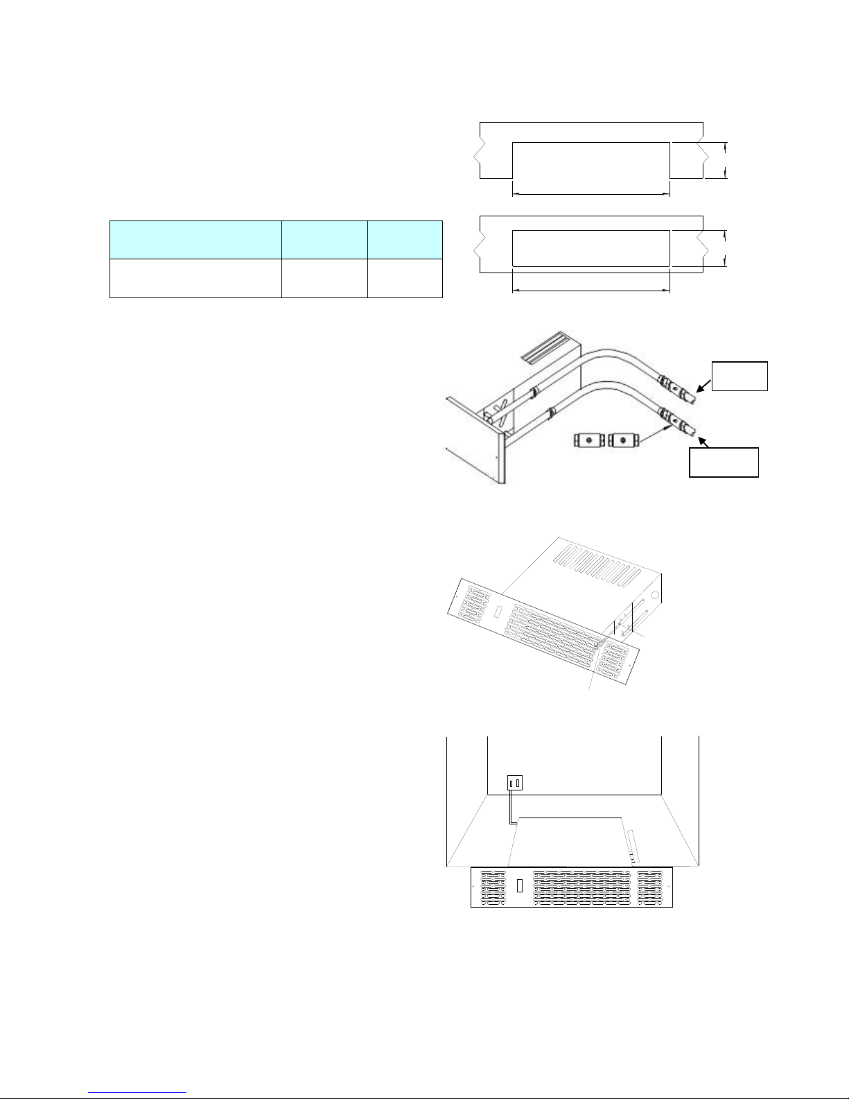
Installation:
1. The heater should be installed by a qualified
plumber. We recommend the use of a knee pad
when installing this product. Cut the opening in
the plinth to the size shown in the table. Use
method A or B.
Model
Width A
Height
B*
KPH
1300/1500/1800/2100
462mm
97mm
* The overall height of the grille is 100mm. Use
A
A
B
B
2. Fit isolating valves (not supplied) to the
system flow and return pipes. Failure to fit
isolating valves may mean that the
product is not serviceable in the event of
failure. Remove and discard the two
protection bungs in the copper pipes and
connect the flexible hoses between
system pipework and heater. Open the
isolating valves and check for leaks.
3. Vent air through bleed screw if
necessary.
Flate heat
screw driver
Bleed Valve
I
O
II
4. Isolate electrical supply and
connect the heater electric cable to
the fused spur (3A). Ensure the
fused spur is not directly above the
heater and is accessible after
installation is complete. Electrical
works should be carried out by a
qualified electrician, in compliance
with local regulations.
I
O
II
Fused Spur
Flow
Return
 Loading...