

thermital THC 150 GREY, THC 800 GREY, THC 210 GREY, THC 600 GREY, THC 1000 GREY Installation, Operation And Maintenance Manual
...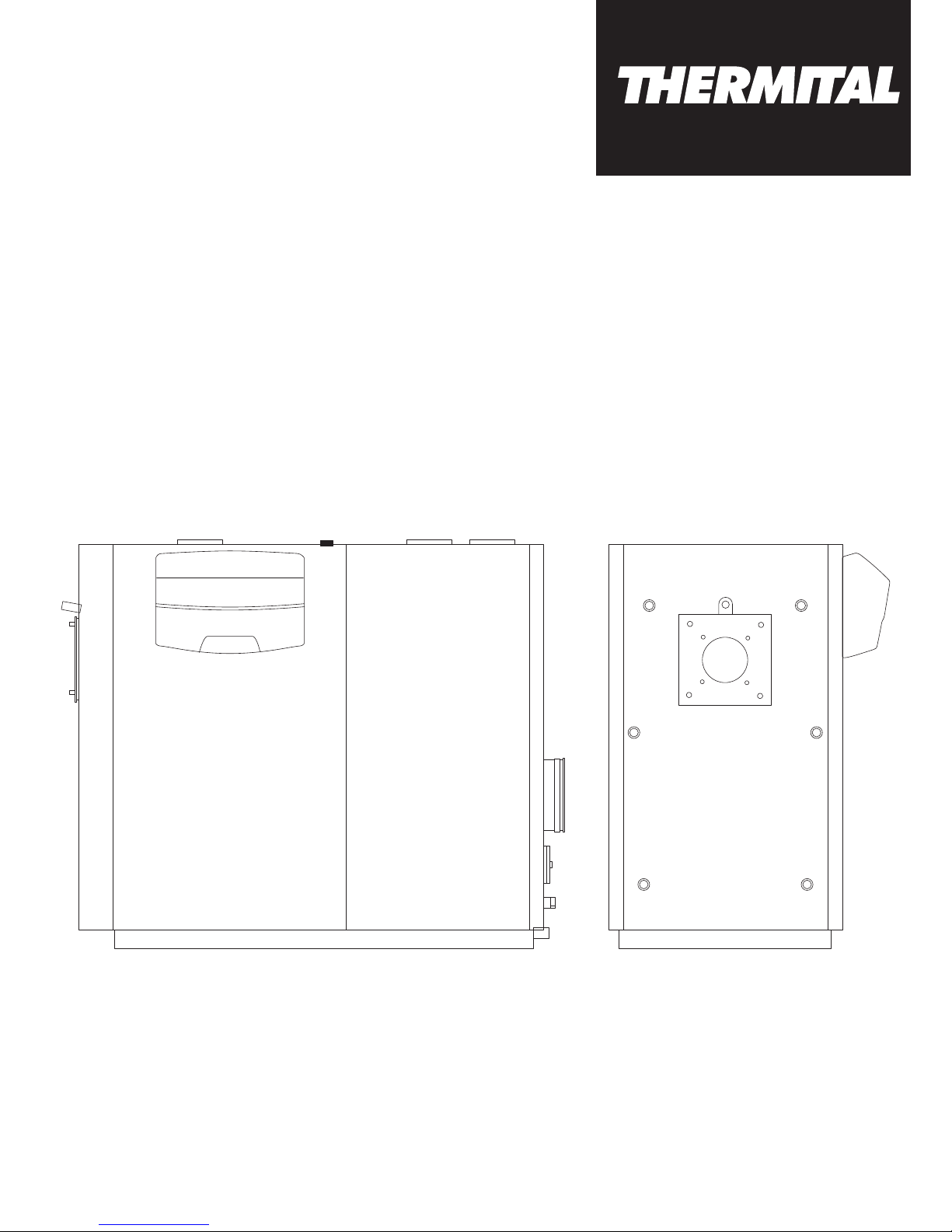
THC 150-1450 GREY
INSTALLATION, OPERATION AND
MAINTENANCE MANUAL
2
ENGLISH
RANGE
MODEL CODE
THC 150 GREY 03504183
THC 210 GREY 03504184
THC 270 GREY 03504185
THC 350 GREY 03504186
THC 450 GREY 03504187
THC 600 GREY 03504188
THC 800 GREY 03504189
THC 1000 GREY 03504190
THC 1250 GREY 03504191
THC 1450 GREY 03504192
THC/C 270 GREY 20012752
THC/C 350 GREY 20012753
THC/C 450 GREY 20012754
THC/C 600 GREY 20012756
ACCESSORIES
For a complete list of accessories and details of their compatibility, refer to the Catalogue.
ENGLISH
Dear Customer,
Thank you for choosing a T boiler. You have purchased a modern, high efficiency, quality product that is designed to give dependable and safe service and to provide
comfort in the home for many years to come. Arrange for your
boiler to be serviced regularly by an authorised Technical Assistance Centre T. Their personnel are specially
trained to keep your boiler efficient and cheap to run. They also
stock any original spare parts that might be required.
This instruction manual contains important instructions and
precautions that must be observed to ensure the efficient functioning of your
THC GREY
boiler.
Please accept our renewed thanks for your purchase
Thermital
CONFORMITY
T
THC GREY
boilers conform to:
- Directive 92/42/EEC on efficiency requirements
- Electromagnetic Compatibility Directive 2014/30/EU
- Low Voltage Directive 2014/35/EU
- Directive 2009/142/EC - Gas Appliances
Models up to 400 kW conform to the Energy-Related Products
Directive 2009/125/EC and to the EU Delegated Regulation
813/2013.

This manual, Code 068672EN - Rev. 32 (04/17) comprises 40 pages.
3
ENGLISH
Contents
CONTENTS
The following symbols are used in this manual:
b
CAUTION! =
Identifies actions that require caution and
adequate preparation.
a
STOP! =
Identifies actions that you MUST NOT do.
This manual, Code
- Rev.
comprises
pages.
GENERAL INFORMATION . . . . . . . . . . . . . . . . . . . . 4
General Safety Information. . . . . . . . . . . . . . . . . . . . . . . . . . 4
Precautions. . . . . . . . . . . . . . . . . . . . . . . . . . . . . . . . . . . . . . 4
Description of the appliance . . . . . . . . . . . . . . . . . . . . . . . . 5
Control panels . . . . . . . . . . . . . . . . . . . . . . . . . . . . . . . . . . . 6
Recommended burners and technical specifications . . . . . 7
THC GREY GTM BLU with power < 400 kW . . . . . . . . . . . . 7
THC GREY PREMIX with power < 400 kW . . . . . . . . . . . . . . 9
THC GREY with power > 400 kW . . . . . . . . . . . . . . . . . . . . 11
Identification. . . . . . . . . . . . . . . . . . . . . . . . . . . . . . . . . . . . 13
SYSTEM MANAGER . . . . . . . . . . . . . . . . . . . . . . . . 14
Putting into service. . . . . . . . . . . . . . . . . . . . . . . . . . . . . . . 14
Preparing for extended periods of disuse . . . . . . . . . . . . . 15
Cleaning . . . . . . . . . . . . . . . . . . . . . . . . . . . . . . . . . . . . . . . 15
Maintenance. . . . . . . . . . . . . . . . . . . . . . . . . . . . . . . . . . . . 15
Useful information . . . . . . . . . . . . . . . . . . . . . . . . . . . . . . . 16
INSTALLER . . . . . . . . . . . . . . . . . . . . . . . . . . . . . . . 17
Unpacking the product . . . . . . . . . . . . . . . . . . . . . . . . . . . 17
Overall dimensions and weights . . . . . . . . . . . . . . . . . . . . 18
Handling. . . . . . . . . . . . . . . . . . . . . . . . . . . . . . . . . . . . . . . 18
Installation premises. . . . . . . . . . . . . . . . . . . . . . . . . . . . . . 19
Water in central heating systems . . . . . . . . . . . . . . . . . . . . 20
Water connections . . . . . . . . . . . . . . . . . . . . . . . . . . . . . . . 22
Condensate evacuation . . . . . . . . . . . . . . . . . . . . . . . . . . . 25
Neutralising the condensate . . . . . . . . . . . . . . . . . . . . . . . 25
Hoses should also be fixed to the floor and suitably protected
whenever possible . . . . . . . . . . . . . . . . . . . . . . . . . . . . . . 27
Installation in B23P configurationin . . . . . . . . . . . . . . . . . . 27
Door hinges . . . . . . . . . . . . . . . . . . . . . . . . . . . . . . . . . . . . 28
Changing the direction of door opening . . . . . . . . . . . . . . 28
Removing the hinge assembly "B" . . . . . . . . . . . . . . . . . . . 30
Earth connection . . . . . . . . . . . . . . . . . . . . . . . . . . . . . . . . 30
Fitting the casing panels . . . . . . . . . . . . . . . . . . . . . . . . . . 31
TECHNICAL ASSISTANCE CENTRE . . . . . . . . . . . 32
Preparing for initial startup . . . . . . . . . . . . . . . . . . . . . . . . . 32
Initial startup. . . . . . . . . . . . . . . . . . . . . . . . . . . . . . . . . . . . 32
Checks during and after initial start-up . . . . . . . . . . . . . . . 33
Maintenance. . . . . . . . . . . . . . . . . . . . . . . . . . . . . . . . . . . . 33
Cleaning the boiler . . . . . . . . . . . . . . . . . . . . . . . . . . . . . . . 34
Troubleshooting . . . . . . . . . . . . . . . . . . . . . . . . . . . . . . . . . 36

4
ENGLISH
GENERAL INFORMATION
GENERAL INFORMATION
GENERAL INFORMATION
General Safety Information
b
The boiler is delivered in separate crates. Check that it
is complete, undamaged and as ordered as soon as you
receive it. Report any discrepancies or damage to the
dealer who sold it.
b
This product must be installed by a legally qualified heating engineer. On completion of the installation, the installer must issue the owner with a declaration of conformity
confirming that the installation has been completed to
the highest standards in compliance with the instructions
provided by T in this instruction manual, and
that it conforms to all applicable laws and standards.
b
This product must only be used for the purpose for which
it is designed and made, as specified by T.
T declines all responsibility, contractual or
other, for damage to property or injury to persons or animals caused by improper installation, adjustment, maintenance or use.
b
If you notice any water leaking from the boiler, disconnect it immediately from the mains electricity supply, shut
off the water supply, and notify your local T’s
Technical Assistance Centre or a qualified heating engineer immediately.
b
Periodically check that operating pressure in the water
circuit is over 1 bar but below the maximum limit specified for the boiler. If this is not the case, contact Technical Assistance Centre T or a professionally
qualified heating engineer.
b
If the boiler is not going to be used for an extended period of time, contact T’s Technical Assistance
Centre or a qualified heating engineer to have it prepared
for shut-down as follows
- Switch the boiler OFF at the control panel
- Turn the main system switch "off"
- Close the fuel cock and heating circuit water cock
- Drain the central heating circuit if there is any risk of
freezing.
b
The boiler must be serviced at least once a year.
b
This instruction manual is an integral part of the boiler.
It must be kept safe and must ALWAYS accompany the
boiler, even if it is sold to another owner or transferred to
another user or to another installation. If you damage or
lose this manual, order a replacement immediately from
your local T’s Technical Assistance Centre.
Precautions
The operation of any appliance that uses fuel, electrical power
and water demands that a number of fundamental safety precautions be respected:
a
It is forbidden to use electrical devices or equipment,
such as switches, appliances, etc. if there is a smell of
gas or un-burnt products. If so:
- Ventilate the room, opening doors and windows
- Close the fuel shut-off cock
- Report the fault immediately to the T's
Technical Assistance Centre or a professionally qualified heating engineer.
a
Do not touch the boiler while barefoot or wet.
a
Never clean or service the boiler without first disconnecting it from the mains electricity supply by turning the
main power switch and the control panel switch OFF.
a
Do not tamper with or adjust the safety or control devices without prior authorisation and instructions from the
manufacturer.
a
Do not plug or block the condensate drain outlet.
a
Never pull, disconnect, or twist the electrical cables coming from the appliance even if it is disconnected from the
mains electricity supply.
a
Do not obstruct or restrict the vents in the room where
the boiler is installed. Adequate ventilation is essential for
correct combustion.
a
Do not expose the boiler to the elements. It is designed
to work indoors.
a
Do not switch the boiler off if outdoor temperature drops
below ZERO (risk of freezing).
a
Do not store containers of flammable substances in the
room where the boiler is installed.
a
Do not allow children or persons with reduced physical,
sensorial or mental abilities or with insufficient experience
and knowledge to operate this system without proper supervision from the person responsible for its safe use.
a
Do not dispose of packaging material into the environment, or leave it within the reach of children, since it can
become a potential hazard. Dispose of packaging material in compliance with applicable legislation.
General information
5
ENGLISH
GENERAL INFORMATION
GENERAL INFORMATION
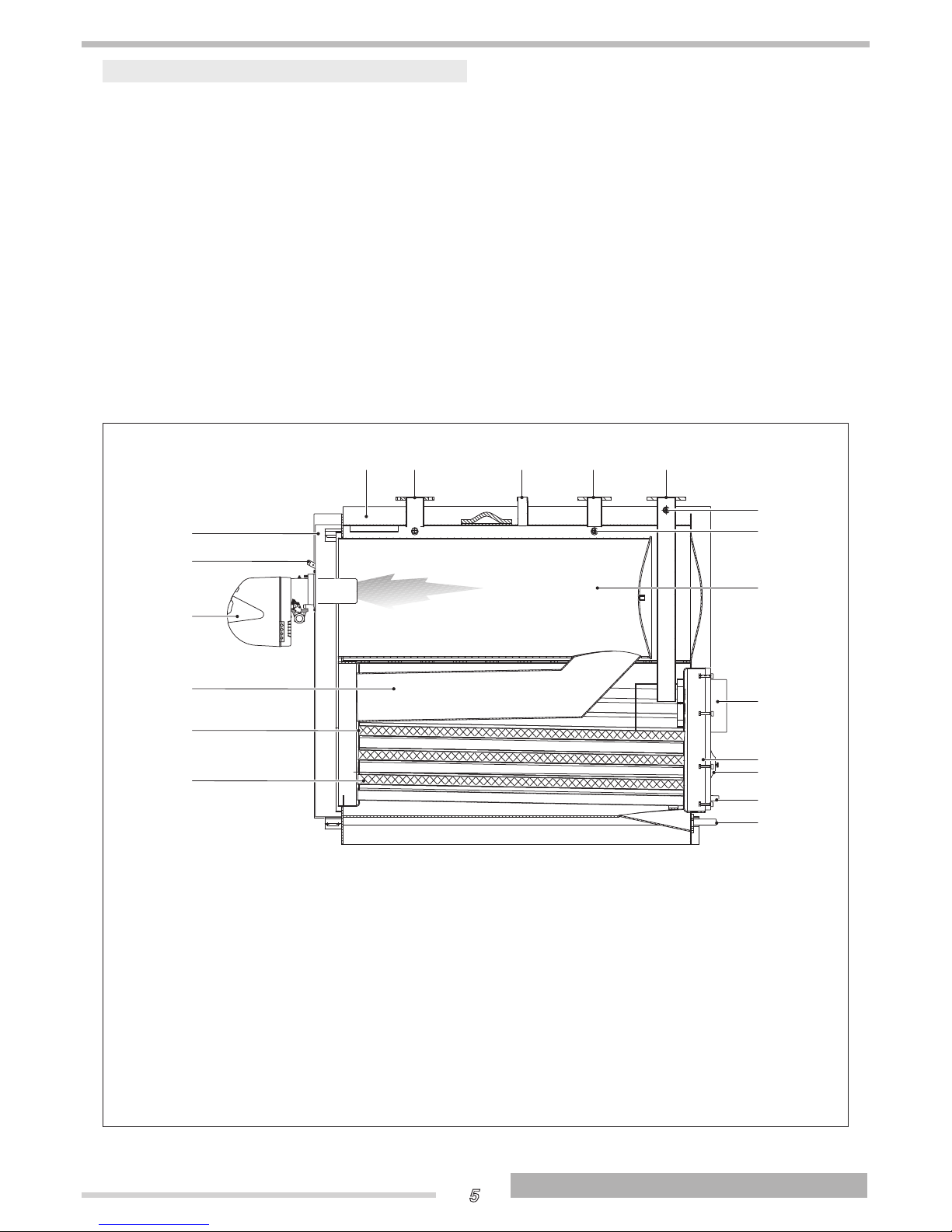
Description of the appliance
THC GREY
T steel boilers are triple flue pass, condensing boilers for installation in a boiler room. While they are
designed primarily for central heating purposes, in conjunction
with a suitable storage cylinder they can also be used to produce domestic hot water.
All parts that come into contact with the combustion gases are
made from titanium stabilised stainless steel to ensure maximum resistance to the corrosive action of acid condensation.
The boiler has been designed with the combustion chamber at
the top and the smooth pipe tube bundle at the bottom to optimise heat exchange and energy efficiency and to maximise
the condensing effect.
The boiler has a high total water content which is differentially
distributed between its top and bottom sections. This allows
outgoing water to reach the set temperature quickly while
maintaining the condensing effect and the water heating time
around the tube bundle for as long as possible.
THC GREY
boilers feature lightly pressurised combustion
chambers for a smoother burner action, and high temperature
resistant, stainless steel turbulators inside the tube bundle for
maximum burner efficiency.
The boiler body is thoroughly insulated with a layer of high
density glass wool.
The paint finished external panelling is also internally insulated
with a layer of high density glass wool.
The boiler’s front door and the flue gas chamber can be opened
completely to facilitate the inspection, maintenance and cleaning of internal parts and to speed up servicing in general.
The front door can open in either direction and can be opened
without removing the burner. The door is factory fitted with
hinges on the left, but these can be reversed if necessary to
suit individual installations.
3
2
1
4 5
6 (*)
7
8 (*)
10
9
11
12
13
14
15
16
19
18
17
1
Burner
2
Flame inspection window with
3
Door
4
Casing
5
Outlet
6
Safety device fitting
7
Heating return (high temperature)
8
Heating return (low temperature)
9
Blind plug
10
Instrument bulb/sensor sockets
11
Combustion chamber
12
Flue gas exhaust
13
Flue gas box
14
Inspection window
15
Condensate outlet
16
Boiler drain
17
Turbulators
18
Flue gas pipes
19
Second flue pass
(*) On the THC 1450 GREY the low temperature heating return (8) is located at the rear of the boiler, and the
safety fitting (6) is flanged.

6
ENGLISH
GENERAL INFORMATION
GENERAL INFORMATION
Control panels
The T control panels that can be used with
T
THC GREY
steel boilers are listed below. These
control panels cater for all the needs of the heating system and
of all the devices installed in it.
TECH CLIMA TOP
for central heating (1 direct zone and 2 mixed
zones) and domestic hot water production with a single stage,
two stage, or modulating burner. Also for controlling solar heating system and cascaded boiler systems.
TECH CLIMA COMFORT
for central heating (1 direct zone and
1 mixed zone) and domestic hot water production with a single stage burner. Also for controlling solar heating system and
cascaded boiler systems.
TECH CLIMA MIX
for controlling 1 additional mixed zone.
7
ENGLISH
GENERAL INFORMATION
GENERAL INFORMATION
Recommended burners and technical specications
THC GREY GTM BLU with power < 400 kW
The burners suggested to obtain the best performance of T THC GREY GTM BLU <400 kW boilers are:
BURNERS BOILER THC GREY GTM BLU
MODEL CODE 150 210 270 350
GAS
BS 3/M 3762350 x
(R)
RS 25/M BLU TC FS1 3910510 x
(R)
RS 25/M BLU TC FS1 3910510 x
(R)
RS 35/M BLU TC FS1 3910610 x
(R)
(R) Reference burner used during performance qualification tests to derive the technical data declared.
NOTE: burners must be fitted with a gas ramp device.
b
See the instruction manual provided with the burner:
- Burner installation
- Electrical connections
- Burner adjustments.
b
To assemble/disassemble the burners equipped with recirculation tube, it might be necessary to remove the latter before
carrying out such operations (strictly comply with the use and maintenance manual of the burner).
8
ENGLISH
GENERAL INFORMATION
GENERAL INFORMATION
Technical specications
DESCRIPTION
BOILER THC GREY GTM BLU
150 210 270 350
Device type
Condensing boiler for central heating
B23
Fuel All gas fuels
Device category See Burner
Rated heat input (Qmax) HCV (LCV)
166,5
(150)
233,1
(210)
299,7
(270)
388,5
(350)
kW
Rated heat input (Qmin) HCV (LCV)
123,2
(111)
167,6
(151)
234,2
(211)
300,8
(271)
kW
Useful (rated) heat output 147 205 264 344
Rated maximum useful heat output (80/60°C) P4 146,6 205,2 264,3 343,7 kW
Rated min. useful heat output (80/60°C) (Pn min) 108,2 147,5 207,2 266,4 kW
30% heat output with return at 30°C (P1) 44,0 61,6 79,3 103,1 kW
Seasonal energy efficiency ηs
92,0 93,0 93,0 93,0 %
Efficiency at rated heat input in high temperature mode
η4 (80-60°C) HCV (LCV)
88,0
(97,7)
88,0
(97,7)
88,2
(97,9)
88,5
(98,2)
%
Useful efficiency at Pn min (80/60°C) HCV (LCV)
87,8
(97,5)
88,0
(97,7)
88,5
(98,2)
88,6
(98,3)
%
Efficiency at 30% rated heat input in low temperature
mode η1 with return at 30°C (HCV)
97,7
(108,5)
98,5
(109,3)
98,4
(109,2)
97,9
(108,7)
%
Losses from stack for sensible heat (Qmax) 1,7 1,7 1,5 1,5 %
Losses from casing with burner on 0,3 0,3 0,5 1,0 %
Constant pressure drop 300 420 540 700 W
Flue gas temperature (∆T) < 45÷75 (*) °C
Emissions at max. heat input Nox (0% O2) < 80 mg/kWh
Flue gas mass flow rate (Qmax) 0,07 0,09 0,12 0,15 kg/sec
Furnace pressure 2,0 2,7 3,2 4,6 mbar
Furnace volume 172,0 172,0 241,0 279,0 dm
3
Tot. volume of flue gas side 272 292 413,0 482,0 dm
3
Heat exchange surface area 8,2 10,4 13,0 16,3 m
2
Volumetric heat load (Qmax) 872 1221 1120 1254 kW/m
3
Specific heat load 18 19,9 20,4 20,9 kW/m
2
Maximum condensate production 18,4 27,4 31,9 40,9 l/h
Maximum working pressure 6 bar
Maximum permitted temperature 110 °C
Maximum operating temperature 95 °C
Pressure drop ∆T 10°C 43,2 36,0 54,0 46,4 mbar
Pressure drop ∆T 20°C 11,3 10,2 16,3 13,4 mbar
Water capacity 323 360 495 555 l
Consumption at full load (Elmax) 650 650 800 800 W
Consumption at part load (Elmin) 132 195 240 240 W
Electrical consumption in standby mode (PSB) 20 20 20 20 W
(*) Depends on return temperature (30-60°C)
b
The stack must guarantee the minimum draught specified by applicable technical standards, assuming zero pressure at
the connection to the flue.
b
Values obtained in combination with the reference burners (R) indicated in the combination table.

9
ENGLISH
GENERAL INFORMATION
GENERAL INFORMATION
THC GREY PREMIX with power < 400 kW
The burners suggested to obtain the best performance of T THC GREY PREMIX <400 kW boilers are:
BURNERS BOILER THC GREY PREMIX
ACCESSORIES
KIT
MODEL CODE 150 210 270 350
BURNER
PLATE
GAS
-
MODULATING
RX 180 S/PV 3790330 x
(R)
4031894
RX 250 S/PV 3790320 x
(R)
4031894
RX 360 S/PV 20067700 x
(R)
20029111
RX 500 S/PV 20077444 x
(R)
20029111
(R) Reference burner used during performance qualification tests to derive the technical data declared.
NOTE: burners must be fitted with a gas ramp device.
b
See the instruction manual provided with the burner:
- Burner installation
- Electrical connections
- Burner adjustments.
b
To assemble/disassemble the burners equipped with recirculation tube, it might be necessary to remove the latter before
carrying out such operations (strictly comply with the use and maintenance manual of the burner).
10
ENGLISH
GENERAL INFORMATION
GENERAL INFORMATION
Technical specications
DESCRIPTION
BOILER THC GREY PREMIX
150 210 270 350
Device type
Condensing boiler for central heating
B23 - B23P(*)
Fuel All gas fuels
Device category See Burner
Rated heat input (Qmax) HCV (LCV)
166,5
(150)
233,1
(210)
299,7
(270)
388,5
(350)
kW
Rated heat input (Qmin) HCV (LCV)
123,2
(111)
167,6
(151)
234,2
(211)
300,8
(271)
kW
Useful (rated) heat output 147 205 264 344
Rated maximum useful heat output (80/60°C) P4 146,6 205,2 264,3 343,7 kW
Rated min. useful heat output (80/60°C) (Pn min) 108,2 147,5 207,2 266,4 kW
30% heat output with return at 30°C (P1) 44,0 61,6 79,3 103,1 kW
Seasonal energy efficiency ηs
92,0 93,0 93,0 93,0 %
Efficiency at rated heat input in high temperature mode
η4 (80-60°C) HCV (LCV)
88,0
(97,7)
88,0
(97,7)
88,2
(97,9)
88,5
(98,2)
%
Useful efficiency at Pn min (80/60°C) HCV (LCV)
87,8
(97,5)
88,0
(97,7)
88,5
(98,2)
88,6
(98,3)
%
Efficiency at 30% rated heat input in low temperature
mode η1 with return at 30°C (HCV)
97,7
(108,5)
98,5
(109,3)
98,4
(109,2)
97,9
(108,7)
%
Losses from stack for sensible heat (Qmax) 1,7 1,7 1,5 1,5 %
Losses from casing with burner on 0,3 0,3 0,5 1,0 %
Constant pressure drop 300 420 540 700 W
Flue gas temperature (∆T) < 45÷75 (**) °C
Emissions at max. heat input Nox (0% O2) 70 <60 mg/kWh
Emissions at max. heat input CO 0 mg/kWh
Flue gas mass flow rate (Qmax) 0,07 0,09 0,12 0,15 kg/sec
Furnace pressure 2,4 2,7 3,2 4,6 mbar
Furnace volume 172,0 172,0 241,0 279,0 dm
3
Tot. volume of flue gas side 272 292 413,0 482,0 dm
3
Heat exchange surface area 8,2 10,4 13,0 16,3 m
2
Volumetric heat load (Qmax) 872 1221 1120 1254 kW/m
3
Specific heat load 18 19,9 20,4 20,9 kW/m
2
Maximum condensate production 18,4 27,4 31,9 40,9 l/h
Maximum working pressure 6 bar
Maximum permitted temperature 110 °C
Maximum operating temperature 95 °C
Pressure drop ∆T 10°C 43,2 36,0 54,0 46,4 mbar
Pressure drop ∆T 20°C 11,3 10,2 16,3 13,4 mbar
Water capacity 323 360 495 555 l
Consumption at full load (Elmax) 400 430 450 1050 W
Consumption at part load (Elmin) 140 160 180 250 W
Electrical consumption in standby mode (PSB) 20 20 20 20 W
(*) The B23P configuration may only be adopted with premix gas burners.
(**) Depends on return temperature (30-60°C)
b
The stack must guarantee the minimum draught specified by applicable technical standards, assuming zero pressure at
the connection to the flue.
b
Values obtained in combination with the reference burners (R) indicated in the combination table.

11
ENGLISH
GENERAL INFORMATION
GENERAL INFORMATION
THC GREY with power > 400 kW
The burners suggested to obtain the best performance of T THC GREY >400 kW boilers are:
BURNERS BOILER THC GREY ACCESSORIES KIT
MODEL CODE 450 600 800 1000 1250 1450
BURNER
FLANGE
HEAD SLIDING
GAS
-
MODULATING
RS 55/M BLU TC FS1 20038484 x 4031188
RS 68/M BLU T.C. 3897406 x 4031196
RS 120/M BLU T.C.D 3897606 x 4031196
RS 120/M BLU T.C.D 3897606 x 4031196
RS 160/M BLU TC FS1 3788006 x 20047680
RS 160/M BLU TC FS1 3788006 x 4031187
RS 50/M MZ TC 3781622 x
RS 70/M TC 3789610 x
RS 100/M TC 3789710 x x
RS 130/M TC 3789810 x
RS 190/M TC 3787623 x
GAS
-
PREMIX
RX 500 S/PV 20077444 x 20067543
RX 850 S/PV 20074219 x 20092252
RX 1000 S/PV 20050087 x 20092252
RX 1000 S/PV 20050087 x 20092252
NOTE: burners must be fitted with a gas ramp device.
b
See the instruction manual provided with the burner:
- Burner installation
- Electrical connections
- Burner adjustments.
b
To assemble/disassemble the burners equipped with recirculation tube, it might be necessary to remove the latter before
carrying out such operations (strictly comply with the use and maintenance manual of the burner).

12
ENGLISH
GENERAL INFORMATION
GENERAL INFORMATION
Technical specications
DESCRIPTION
BOILER THC GREY
450 600 800 1000 1250 1450
Device type
Condensing boiler for central heating
B23 - B23P(*)
Fuel All gas fuels
Device category See Burner
Rated heat input (Qmax) HCV (LCV)
499,5
(450)
666,0
(600)
888,0
(800)
1110,0
(1000)
1387,5
(1250)
1609,5
(1450)
kW
Rated heat input (Qmin) HCV (LCV)
389,6
(351)
500,6
(451)
667,1
(601)
889,1
(801)
1111,1
(1001)
1388,6
(1251)
kW
Useful (rated) heat output 442 589 786 982 1228 1424
Rated maximum useful heat output (80/60°C) P4 441,9 589,2 785,6 982,0 1227,5 1423,9 kW
Rated min. useful heat output (80/60°C) (Pn min) 345,0 443,3 590,8 787,4 984,0 1229,7 kW
30% heat output with return at 30°C (P1) 132,6 176,8 235,7 294,6 368,3 427,2 kW
Efficiency at rated heat input in high temperature mode
η4 (80-60°C) HCV (LCV)
88,5
(98,2)
88,5
(98,2)
88,5
(98,2)
88,5
(98,2)
88,5
(98,2)
88,5
(98,2)
%
Useful efficiency at Pn min (80/60°C) HCV (LCV)
88,6
(98,3)
88,6
(98,3)
88,6
(98,3)
88,6
(98,3)
88,6
(98,3)
88,6
(98,3)
%
Efficiency at 30% rated heat input in low temperature
mode η1 with return at 30°C (HCV)
97,9
(108,7)
97,9
(108,7)
97,9
(108,7)
97,9
(108,7)
97,9
(108,7)
97,9
(108,7)
%
Losses from stack for sensible heat (Qmax) 1,9 %
Losses from casing with burner on 0,6 %
Constant pressure drop <0,2 %
Flue gas temperature (∆T) < 45÷75 (**) °C
Flue gas mass flow rate (Qmax) (***) 0,20 0,26 0,33 0,43 0,54 0,63 kg/sec
Furnace pressure 5,0 5,5 5,7 6,3 6,8 7,4 mbar
Furnace volume 442 496 753 845 1037 1249 dm
3
Tot. volume of flue gas side 737 860 1290 1454 1763 2097 dm
3
Heat exchange surface area 21,8 28,8 39,6 46,5 56,2 62,3 m
2
Volumetric heat load (Qmax) 1018 1210 1062 1183 1205 1161 kW/m
3
Specific heat load 20,1 20,3 18,5 21,0 21,7 22,6 kW/m
2
Maximum condensate production 52,2 73,8 88,0 111,4 132,7 159,5 l/h
Maximum working pressure 6 bar
Maximum permitted temperature 110 °C
Maximum operating temperature 95 °C
Pressure drop ∆T 10°C 33,8 30,2 128,7 121,5 100,4 150,1 mbar
Pressure drop ∆T 20°C 9,0 8,5 28,7 30,6 28,4 36,3 mbar
Water capacity 743 770 1320 1395 1825 1900 l
(*) The B23P configuration may only be adopted with premix gas burners.
(**) Depends on return temperature (30-60°C)
(***) At Pn max and Tm = 80°C, Tr = 60°C e CO2 = 10,3%
b
The stack must guarantee the minimum draught specified by applicable technical standards, assuming zero pressure at
the connection to the flue.
 Loading...