

thermital TBSS 150, TBSS 430, TBSS 200, TBSS 300, TBSS 550 Installation, Operation And Maintenance Manual
...Page 1
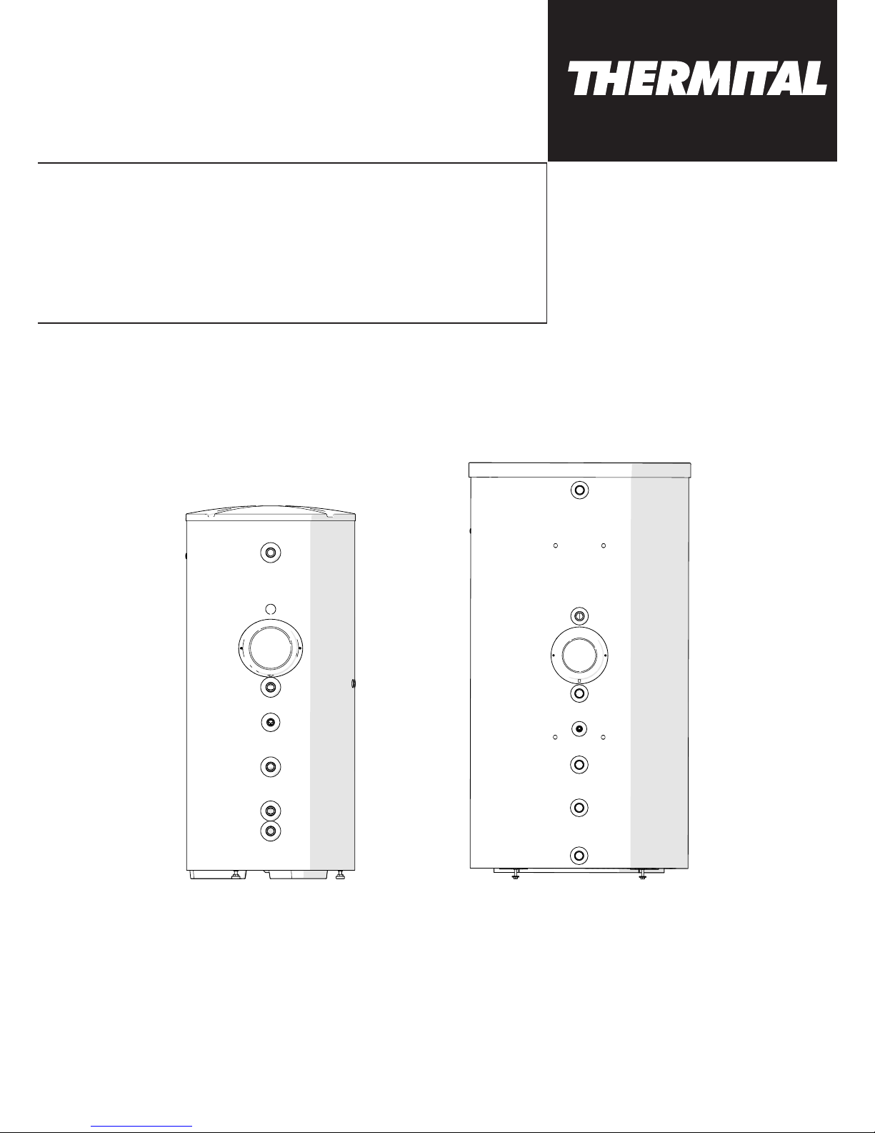
TBSS 150-200-300-430-550 TBSS 800-1000
TBSS
INSTALLATION, OPERATION AND
MAINTENANCE MANUAL
Page 2

This manual, Code 20128955 - Rev. 2 (01/18) comprises 8 pages.
2
ENGLISH
GENERAL INFORMATION
GENERAL INFORMATION
RANGE
MODEL CODE
TBSS 150 20124177
TBSS 200 20124178
TBSS 300 20124179
TBSS 430 20124180
TBSS 550 20124181
TBSS 800 20132275
TBSS 1000 20132276
ACCESSORIES
For a complete list of accessories and details of their compatibility, refer to the Catalogue.
Dear heating engineer,
We would like to congratulate you on having recommended a
T Storage cylinder unit: a modern product that's
capable of ensuring a high degree of reliability, efficiency,
quality and safety.
While your technical skills and knowledge will certainly be
more than sufficient, this booklet contains all the information
that we have deemed necessary for the device's correct and
easy installation.
Thank you again, and keep up the good work,
Thermital
CONFORMITY
T storage cylinders conform to DIN 4753-3 and
UNI EN 12897 standards.
CONTENTS
The following symbols are used in this manual:
b
CAUTION! =
Identifies actions that require caution and
adequate preparation.
a
STOP! =
Identifies actions that you MUST NOT do.
GENERAL SAFETY INFORMATION
b
Check that the product is complete, undamaged and as
ordered as soon as you receive it. Report any discrepancies or damage to the T dealer who sold it.
b
This product must be installed by a legally qualified heating engineer. On completion of the installation, the installer must issue the owner with a declaration of conformity
confirming that the installation has been completed to
the highest standards in compliance with the instructions
provided by T in this instruction manual, and
that it conforms to all applicable laws and standards.
b
This product must only be used for the purpose for which
it is designed and made, as specified by
T.
T declines all responsibility, contractual or
other, for damage to property or injury to persons or animals caused by improper installation, adjustment, maintenance or use.
b
The product must be serviced at least once a year. Servicing must be arranged in advance with the T
Technical Assistance Centre.
b
All servicing and repairs must be performed by a qualified heating engineer.
b
If water leaks from the storage cylinder, turn off the water
supply and contact T’s Technical Assistance
Centre or a qualified heating engineer immediately.
b
If the product is not going to be used for an extended
period of time, contact the manufacturer’s Technical Assistance Centre to have at least the following operations
performed:
- Close the shut-off cocks for the domestic hot water circuit
- Shut down the boiler connected to the storage cylinder
as instructed in its own manual
- Switch the storage cylinder OFF at the control panel (if
fitted) and at the mains power switch
- Drain the central heating circuit and domestic hot water
circuit if there is any risk of freezing.
b
This instruction manual is an integral part of the product. It must be kept safe and must ALWAYS accompany
the product, even if it is sold to another owner or transferred to another user or to another installation. If you
lose this manual, order a replacement immediately. Keep
the product purchase documents to be presented to the
T authorised Technical Assistance Centre to
request a service call under warranty.
This manual, Code
- Rev.
comprises
pages.
ENGLISH
General information
GENERAL INFORMATION . . . . . . . . . . . . . . . . . . . . 2
General Safety Information. . . . . . . . . . . . . . . . . . . . . . . . . . 2
Precautions. . . . . . . . . . . . . . . . . . . . . . . . . . . . . . . . . . . . . . 3
Description of the appliance . . . . . . . . . . . . . . . . . . . . . . . . 3
Identification. . . . . . . . . . . . . . . . . . . . . . . . . . . . . . . . . . . . . 3
System layout . . . . . . . . . . . . . . . . . . . . . . . . . . . . . . . . . . . . 3
Technical specifications . . . . . . . . . . . . . . . . . . . . . . . . . . . . 4
INSTALLATION . . . . . . . . . . . . . . . . . . . . . . . . . . . . . 6
Unpacking the product . . . . . . . . . . . . . . . . . . . . . . . . . . . . 6
Assembly of the insulation and the lining (models 800 - 1000) . .
6
Place of installation. . . . . . . . . . . . . . . . . . . . . . . . . . . . . . . . 6
Installation in older systems and systems requiring
modernisation . . . . . . . . . . . . . . . . . . . . . . . . . . . . . . . . . . 6
Water quality requirements. . . . . . . . . . . . . . . . . . . . . . . . . . 6
Water connections . . . . . . . . . . . . . . . . . . . . . . . . . . . . . . . . 7
Recycling and disposal . . . . . . . . . . . . . . . . . . . . . . . . . . . . 8
END USER . . . . . . . . . . . . . . . . . . . . . . . . . . . . . . . . . 8
Start-up. . . . . . . . . . . . . . . . . . . . . . . . . . . . . . . . . . . . . . . . . 8
Temporary shutdown . . . . . . . . . . . . . . . . . . . . . . . . . . . . . . 8
Preparing for extended periods of disuse . . . . . . . . . . . . . . 8
External maintenance. . . . . . . . . . . . . . . . . . . . . . . . . . . . . . 8
Page 3
3
ENGLISH
GENERAL INFORMATION
GENERAL INFORMATION
PRECAUTIONS
The operation of any appliance that uses electrical power demands that a number of fundamental safety precautions be
respected. In particular:
a
Never attempt to install the system without using suitable
personal protection equipment and without following all
applicable occupational safety standards.
a
Do not touch the product when barefoot or wet if it has
any electrical accessories installed in it.
a
Never clean or service the storage cylinder without first
turning the mains power switch OFF to disconnect all
electrical accessories (if fitted) from the mains electricity
supply.
a
Never pull, disconnect, or twist any electrical cables
coming from the appliance even if it is disconnected from
the mains electricity supply.
a
Do not expose the storage cylinder to the elements. It is
not designed for use outdoors.
a
Do not allow children or infirm persons to operate the
system unsupervised.
a
Do not dispose of packaging material into the environment, or leave it within the reach of children, since it can
become a potential hazard. Dispose of packaging material in compliance with applicable legislation.
DESCRIPTION OF THE APPLIANCE
T
TBSS
boilers produce domestic hot water for
storage purposes and are available in seven different models.
Their most important technical features are:
- the storage cylinder and coil are specially designed
and shaped for optimum performance in terms of stratification, heat exchange and replenishment times
- internal glazing, bacteriologically inert, to ensure the
maximum hygiene of treated water, reduce limescale
deposits and make cleaning operations easier
- CFC-free polyurethane insulation and an elegant external casing reduce heat loss
- a flange is provided for easy cleaning and maintenance
of the anti-corrosion magnesium anode.
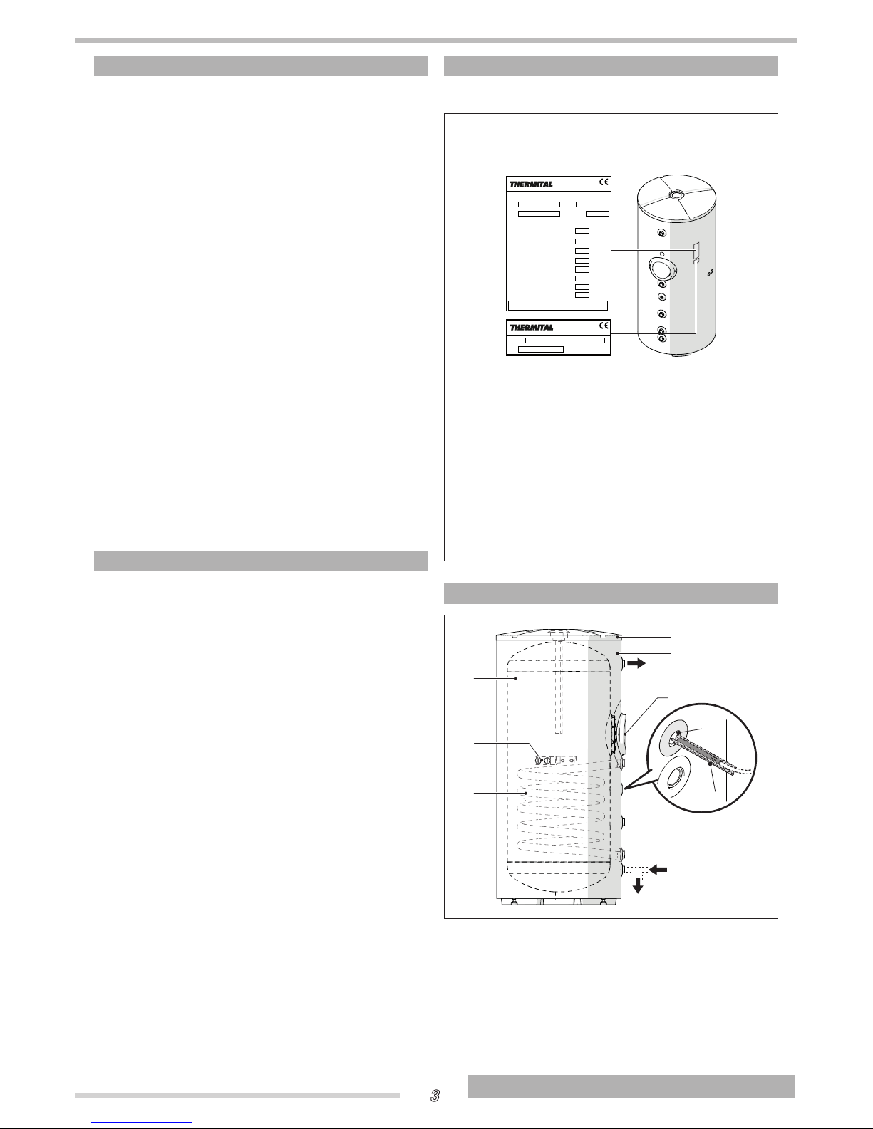
IDENTIFICATION
The T
TBSS
solar heaters can be identified by:
Data plate
This lists the technical specifications and performance of
the product.
BALLON
Modele
Model
Fabrication
Code
Année
W
l
bar
W
kW
l/1'
BOLLITORE
Modello
Codice
Matricola
Anno
m
2
kW
T067850IFE
T067850IFE
BOILER
Serial number
Year
V-Hz
Potenza elettrica assorbita
Puissance élect. absorbée
Electrical consumption
Alimentazioneelettrica
Alimentat. élect.
Power supply
Dispersioni secondo EN 12897
Déperditions selon EN 12897
Heat loss according to EN 12897
Matricola
Fabrication
Serial number
Modello
Modele
Model
Max pot. assorb.
Puiss. absor.
Power abs.
Code
Massima potenza assorbita [T° Primario 80°C]
Puissance absorbée serpentin [T° Primaire 80°C]
Power absorbed by the coil [T° primary 80°C]
Produzione acqua calda sanitaria - serp. [∆T20°C]
Production eau chaude sanitaire - serp. [∆T 20°C]
Domestic hot water production – coil [∆T 20°C]
Superficie serpentino
Surface serpentin
Coil heat exchange surface area
Press. esercizio max.
Pression service max.
Maximum working pressure of storage cylinder
Capacità del bollitore
Capacité ballon
Storage cylinder capacity
Collegamento di terraobbligatorio - Raccordement a la terre obligatoire
Obligatory ground connection
RIELLO S.p.A.
Via Ing.Pilade Riello 7
37045 Legnago (VR) - ITALY
RIELLO S.p.A.
Via Ing.Pilade Riello 7
37045 Legnago (VR) - ITALY
Serial number plate
This specifies the serial number and model.
b
If these plates or any other means of clearly identifying the product are defaced, removed or lost, proper
installation and servicing may be rendered difficult.
b
On models 800 and 1000 the technical data plate and
serial number plate must be applied (by the installer)
after the insulation has been fitted.
SYSTEM LAYOUT
UAC
EAF
SB
P
M
1
3
6
5
4
2
1
Storage cylinder
2
Preset for lifting handles (accessory) and/
or device grounding
point
3
Coil
4
Flange for heater inspection
5
Insulation
6
Cover
P
Socket
M
Guide
UAC
Domestic hot water
outlet
EAF
Domestic cold water
inlet
SB
Storage cylinder drain
Page 4
4
ENGLISH
GENERAL INFORMATION
GENERAL INFORMATION
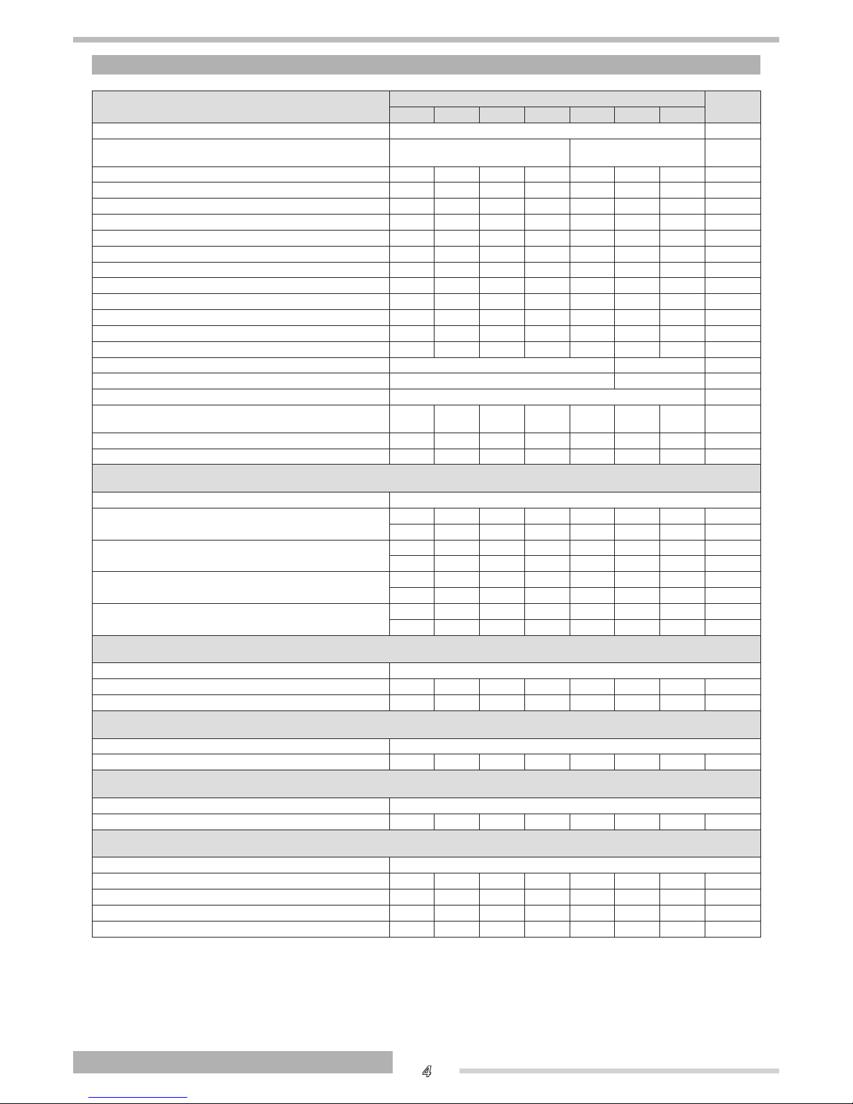
TECHNICAL SPECIFICATIONS
DESCRIPTION
TBSS
150 200 300 430 550 800 1000
Type of storage cylinder Vertical, glazed
Heat exchanger layout Vertical, with elliptical section
Vertical, with circular
section
Storage cylinder capacity 162 207 305 445 555 735 890 l
Diameter of storage cylinder with insulation 604 604 604 755 755 974 974 mm
Diameter of storage cylinder without insulation - - - - - 790 790 mm
Height with insulation 1088 1338 1838 1644 1988 1835 2155 mm
Height without insulation - - - - - 1745 2070 mm
Insulation thickness 52 52 52 52 52 92 92 mm
Total net weight 62 78 103 131 157 203 225 kg
Quantity/diameter/length of magnesium anode
1/33/300 1/33/300 1/33/450 1/33/450 1/33/520 1/40/600 1/40/600
mm
Flange internal diameter 130 130 130 130 130 130 130 mm
Diameter/length of sensor sockets 16/180 16/180 16/180 16/180 16/180 16/180 16/180 mm
Coil water capacity 4,25 6,9 8,5 10,0 19,3 21,0 24,4 l
Coil heat exchange surface area 0,85 1,38 1,7 2 2,3 2,5 2,9 m
2
Maximum operating pressure of storage cylinder 10 7 bar
Maximum operating pressure of coils 10 7 bar
Maximum operating temperature 99 °C
Discharges according to EN 12897:2006 ∆T=45 °C
(ambient 20°C and storage at 65°C)
55 58 68 73 84 95 103 W
Discharges according to UNI 11300 1,22 1,31 1,51 1,62 1,87 2,11 2,29 W/K
Energy class B B B B B B B
Continuous availability of domestic water (DHW 10-45°C) at the different coil inlet temperatures and with the indicated
delta (∆) T°.
Coil delivery temperature
80°C ∆T 20°C
27 39 49 56 66 69 75 kW
660 950 1185 1380 1645 1728 1860 l/h
70°C ∆T 20°C
19 28 37 40 49 53 57 kW
480 690 921 955 1207 1300 1403 l/h
60°C ∆T 10°C
11 17 22 24 35 37 39 kW
280 410 528 580 860 910 960 l/h
50°C ∆T 10°C
8 9 13 15 17 19 21,7 kW
190 200 319 370 408 460 534 l/h
Set-up time required to heat the boiler to 60°C (coil probe point reference) with primary exchanger at the indicated delivery temperature and with the indicated delta (∆) T°.
Coil delivery temperature
80°C ∆T 20°C 35 34 38 37 32 50 52 min
70°C ∆T 20°C 39 40 42 43 48 74 77 min
Set-up time required to heat the boiler to 55°C (coil probe point reference) with primary exchanger at the indicated delivery temperature and with the indicated delta (∆) T°.
Coil delivery temperature
60°C ∆T 10°C 45 43 48 52 50 76 82 min
Set-up time required to heat the boiler to 45°C (coil probe point reference) with primary exchanger at the indicated delivery temperature and with the indicated delta (∆) T°.
Coil delivery temperature
50°C ∆T 10°C 56 53 55 60 58 80 94 min
NL thermal efciency coefcient according to DIN 4708. The NL index indicates a number of apartments having 3.5 people that can be fully supplied, with a 140 l bathtub and two other drawing points.
Coil delivery temperature
80°C 1,84 2,6 3,28 4,06 4,87 5,9 6,83
70°C 1,44 2,01 2,63 3,12 3,86 4,9 5,67
60°C 1 1,36 1,81 2,2 2,5 3,7 4,23
50°C 0,75 0,86 1,26 1,59 2,01 2,37 2,68
Page 5
5
ENGLISH
GENERAL INFORMATION
GENERAL INFORMATION
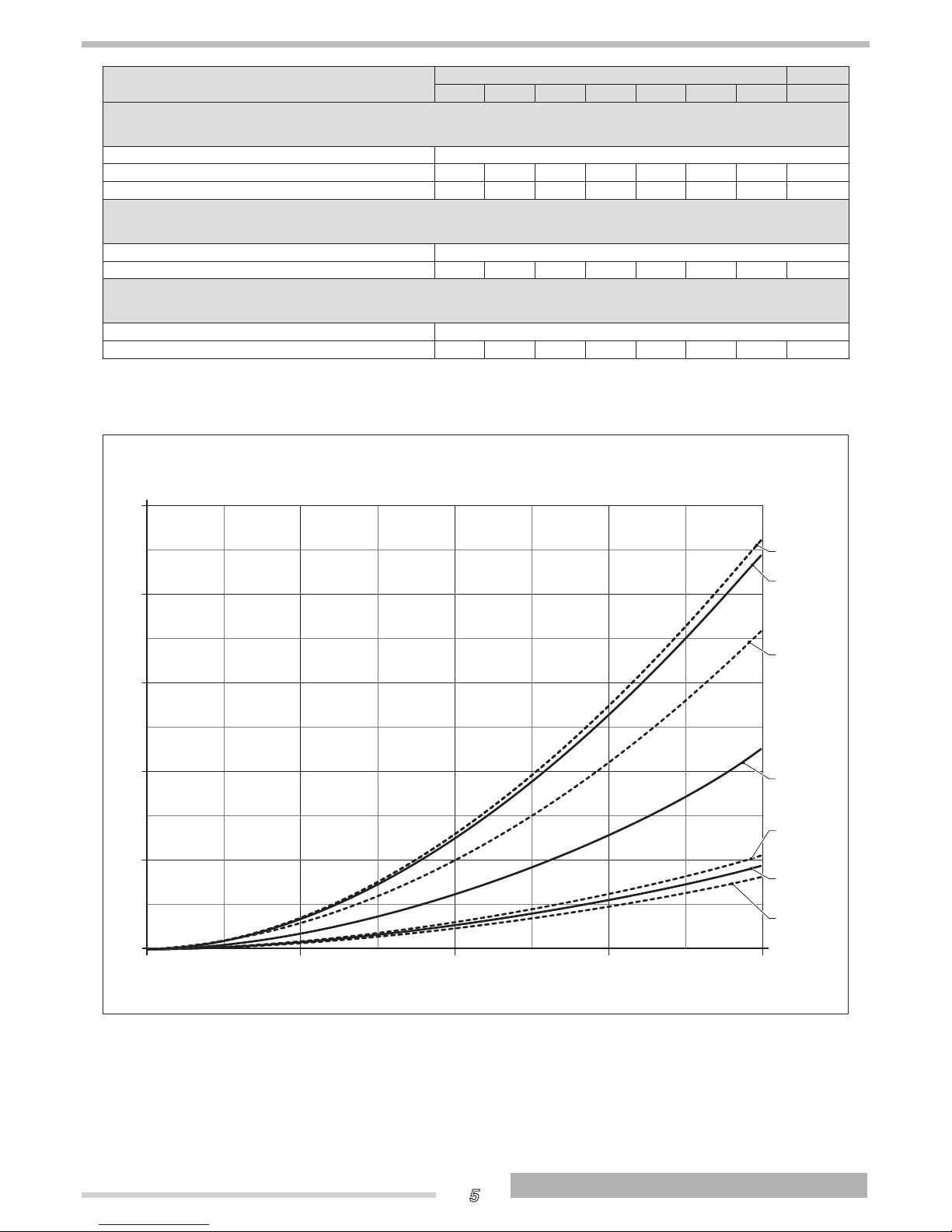
EMPTYING IN 10’
TBSS
150 200 300 430 550 800 1000
Quantity of domestic water obtained in 10’ with boiler pre-heated to 60°C (coil probe point reference) and primary
exchanger at the indicated delivery temperature, considering an increase of the domestic water temperature of 30°C
between inlet and outlet (according to EN 12897).
Coil delivery temperature
80°C 272 347 440 653 826 1270 1583 l
70°C 250 320 410 585 731 1177 1445 l
Quantity of domestic water obtained in 10’ with boiler pre-heated to 55°C (coil probe point reference) and primary
exchanger at the indicated delivery temperature, considering an increase of the domestic water temperature of 30°C
between inlet and outlet (according to EN 12897).
Coil delivery temperature
60°C 223 265 370 530 697 975 1163 l
Quantity of domestic water obtained in 10’ with boiler pre-heated to 45°C (coil probe point reference) and primary
exchanger at the indicated delivery temperature, considering an increase of the domestic water temperature of 30°C
between inlet and outlet (according to EN 12897).
Coil delivery temperature
50°C 170 208 315 428 590 720 812 l
Pressure drops
COIL
PRESSURE DROP (mbar)
800
600
400
1000
200
0
0 1000 2000 3000 4000
200
150
550
300
430
800
1000
FLOW RATE (l/h)
Page 6
6
ENGLISH
INSTALLATION
INSTALLATION
UNPACKING THE PRODUCT
Heaters T
TBSS
are supplied in a single package
on a wooden pallet.
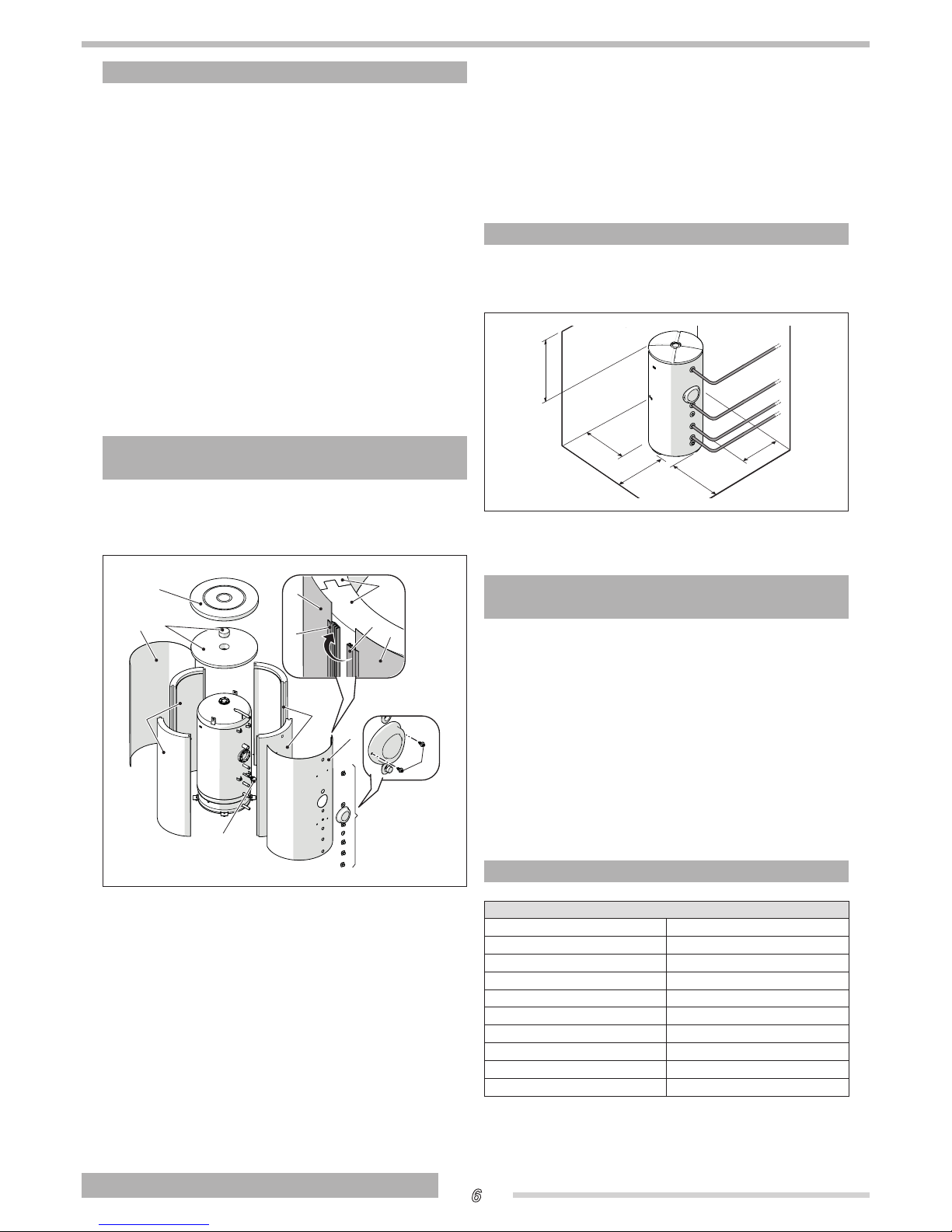
The insulation and the lining components of the models 800
and 1000 are supplied separately from the structural work and
are to be assembled upon receiving the product as described
in the paragraph "Assembly of the insulation and the lining
(models 800 - 1000)". For these models the magnesium anode
is supplied in a cardboard box.
The following items are delivered in a plastic bag inside the
packaging:
- Instruction manual
- Bar code label
- Hydraulic test certificate
- Energy label (to be applied to device upon installation)
- No. 4 adjustable feet to be mounted during installation
(for models 800-1000 only).
b
The instruction manual is an integral part of the solar storage cylinder. Once located, read it thoroughly and keep
it safe.
b
For handling operations, thoroughly follow the instructions on device package label.
ASSEMBLY OF THE INSULATION AND
THE LINING (MODELS 800 - 1000)
The assembly of the insulation and lining components must
be performed at the site of installation to facilitate passage
through any doors and/or entries to the room.
4
5
2
1
7
3
3
1
6
1
3
L
3
L
Proceed as follows:
- Fit the magnesium anode (6) with its seal in the sleeve
and fix it in place
- Assemble the insulating covers (1) around the body of
the heater, making sure that the engagement points on
the edges are positioned correctly. The edges are not
required to be closed completely
- Place the front protection plate (3) correctly on the attachments
- Place the washers on the attachments and the protection for the inspection flange (4)
- Place the rear protection plate by closing the interlocking flaps (L) without closing completely (leave one tooth
open)
- Apply the upper insulation (2) and the upper cover (5)
(in order to insert the cover, exert a light and homogeneous pressure)
- Close the interlocking flaps (L) completely, which were
previously left with an open tooth
- Fit the cover of the inspection flange using the two
self-tapping screws (7) provided
- Apply the technical data plate and serial number plate.
If disassembling is required, proceed in reverse order.
b
Wear suitable personal protective equipment and use
suitable safety devices.
PLACE OF INSTALLATION
T
TBSS
storage cylinders can be installed in any
room where there is no specific requirement for an electrical
protection rating higher than IP X0D.
≥ 0,3 m
≥ 0,3 m
≥ 0,3 m
≥ 0,6 m
≥ 0,7 m
NOTE:
the above-indicated dimensions are recommended for
a correct maintenance and access to the device.
INSTALLATION IN OLDER SYSTEMS AND
SYSTEMS REQUIRING MODERNISATION
When installing T
TBSS
storage cylinders in old
systems or systems requiring modernisation, always perform
the following checks.
- Make sure that the system is fitted with safety and control devices in accordance with applicable legislation
and standards
- Make sure that the central heating circuit has been
flushed out to remove all sludge and lime scale, and
has been vented and seal tested
- Make sure that a suitable water treatment system is installed if the quality of the supply/recirculation water so
demands. (Refer to the reference values listed in the
table alongside.)
WATER QUALITY REQUIREMENTS
REFERENCE VALUES
pH 6-8
Electrical conductivity less than 200 μS/cm (25°C)
Chlorine ions less than 50 ppm
Sulphuric acid ions less than 50 ppm
Total iron less than 0.3 ppm
Alkalinity M less than 50 ppm
Total hardness less than 35°F
Sulphur ions none
Ammonia ions none
Silicon ions less than 30 ppm
The values above ensure proper operation of the system. Refer
to the limit values specified in the current standards and regulations on the installation site.
Installation
Page 7
7
ENGLISH
INSTALLATION
INSTALLATION
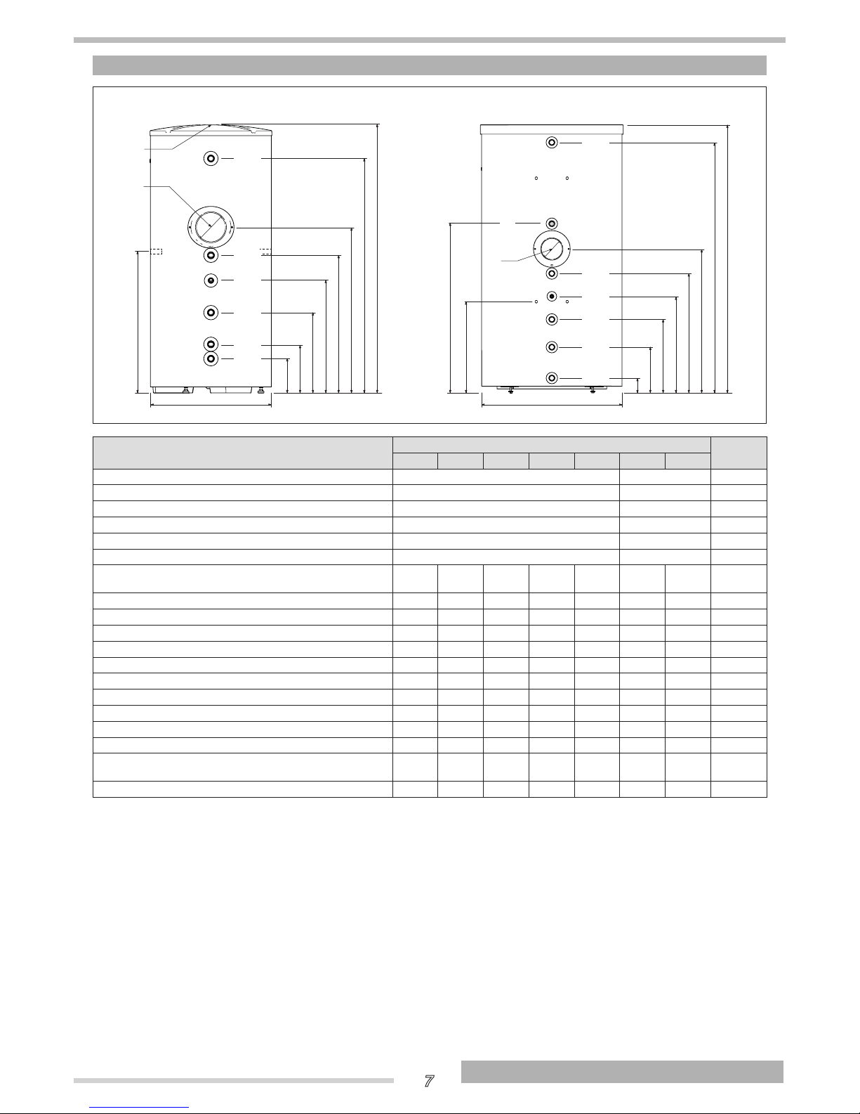
WATER CONNECTIONS
A
B
C
D
E
F
G
H
UAC
MC
Psc
RL
RC
EAF
AD
L
I
DF
TBSS 150 - 550 TBSS 800 - 1000
A
B
C
D
E
F
G
H
UAC
MC
Psc
RL
RC
EAF
M
L
I
DF
AD
DESCRIPTION
TBSS
150 200 300 430 550 800 1000
UAC Domestic hot water outlet 1” M 1”1/4 M Ø
MC Outlet from boiler 1” M 1” M Ø
RC Return to boiler 1” M 1” M Ø
RL DHW recirculation 1” M 1” M Ø
EAF Domestic cold water inlet 1” M 1”1/4 M Ø
Psc Diameter/length of boiler sensor socket 16/180 16/180 mm
AD Quantity/diameter/length of magnesium an-
ode
1/33/300 1/33/300 1/33/450 1/33/450 1/33/520 1/40/600 1/40/600
mm
DF Flange internal diameter 130 130 130 130 130 130 130 mm
A 171 171 171 208 207 75 75 mm
B 243 243 253 304 303 289 289 mm
C 323 401 475 462 543 465 529 mm
D 431 561 635 622 717 641 706 mm
E 523 687 793 780 875 799 864 mm
F 663 827 993 980 1075 969 1034 mm
G 920 1170 1670 1440 1784 1707 2032 mm
H 1088 1338 1838 1644 1988 1835 2155 mm
I 604 604 604 755 755 974 974 mm
L M8 threaded inserts for grounding point/ac-
cessory handles connection
700 700 700 700 700 604 604 mm
M - - - - - 1144 1209 mm
b
We recommend that you install isolating valves in the outlet and return lines.
b
Check the efficiency of the seals when filling/refilling the storage cylinder.
b
In case of a probe, any electric junction between probe cable and extensions for the connection to the electric panel must
be soldered and protected with a sheath or a suitable electric insulation.
b
To access the M8 threaded inserts on models 800 - 1000 the external covering has to be removed as instructed in "Assembly of the insulation and the lining (models 800 - 1000)"
b
Install the magnesium anode supplied (for the models 800 and 1000).
Page 8
8
ENGLISH
END USER
END USER
RECYCLING AND DISPOSAL
The device is primarily composed of:
Material Component
steel structural work
PU (polyurethane) insulation (models 150 - 550)
polystyrene - polyester felt insulation (models 800 - 1000)
PE (polyethylene) water connection washers
ABS (acrylonitrile-butadiene-styrene) lining and covers
At the end of the device's useful life, these components must be separated and disposed of according to current regulations in
the country of installation.
END USER INSTRUCTIONS
Refer to the GENERAL SAFETY INFORMATION and PRECAUTIONS section for safety-related information.
START-UP
The heater commissioning must be performed by Technical
Assistance Centre personnel.
Under certain circumstances, such as after long periods of
disuse, the user may need to re-start it without involving the
Technical Assistance Centre. Before doing so, perform the following checks and operations.
- Check that the supply cocks in the domestic water circuit are all open
- Switch the electricity supply ON at the mains power
switch and at control panel switch (if fitted).
TEMPORARY SHUTDOWN
To reduce to the environmental impact and save energy, in
case of brief absences, week-ends, short trips, etc., and with
external temperatures above 0°C, set the heater temperature
control, where available, to the minimum value.
b
If the temperature to which the heater is exposed can
fall below 0°C (frost hazard), perform the operations described in paragraph "Preparing for extended periods of
disuse".
PREPARING FOR EXTENDED PERIODS
OF DISUSE
If the storage cylinder is not going to be used for an extended
period of time, ask the manufacturer’s Technical Assistance
Centre to make the system safe.
EXTERNAL MAINTENANCE
Clean the outside of the storage cylinder with a soft cloth
damped in soapy water.
a
Do not use abrasive products, petrol or triethylene.
End user
RIELLO S.p.A.
Via Ing. Pilade Riello, 7
37045 - Legnago (VR)
www.thermital.it
The manufacturer strives to continuously improve all products. Appearance,
dimensions, technical specications, standard equipment and accessories are
therefore liable to modication without notice.
 Loading...