

thermital MODEX ACS 40 E Instruction Manual

1
ENGLISH
THERMITAL MODEX ACS 40 E
The ACS 40 E is an instant domestic hot water mixer. It uses a brazed, stainless steel plate heat exchanger and is desi-
gned for use in combination with DHW storage cylinders.
The product is equipped with two filling/drain cocks. When the shut-off valves are closed, these can also be used to flush
out the heat exchanger.
A domestic hot water recirculation kit is available for further convenience.
The ACS 40 E instant hot water mixer comes complete with an insulated frame.
Description Qty.
1 DHW mixer in packing 1
2 Instruction manual 1
DESCRIPTION
CONTENTS OF KIT
GENERAL SAFETY INFORMATION AND PRECAUTIONS
READ THIS MANUAL THOROUGHLY BEFORE PERFORMING ANY WORK ON THE PRODUCT.
The manufacturer reserves the right to modify the product without notice for the purpose of introducing technical improvements or to facilitate production, installation and positioning. The illustrations in this manual may therefore differ
slightly from the actual product. The safety of the product and the accuracy of the instructions provided are nevertheless
guaranteed.
This manual forms an integral part of the product itself and must be kept in a safe place in order to avoid damage and to
permit rapid consultation throughout the working life of the product.
Ideally, this manual should be kept with the product where it can be consulted whenever needed. The manual should
always accompany the product if sold or transferred to a new owner, or stay with it if the owner moves house and leaves
it behind, so that the next user can consult it.
cod. Doc-0072219 - Rev. 4 (05/17)

2
GENERAL SAFETY INFORMATION
INSTALLATION
Disconnect the product from the mains power supply before commencing any work on it.
The product must be installed in conformity to the laws and standards applicable in the country of installation.
The manufacturer’s responsibility ends with the supply of the product. The product must be installed using best professional practices, in conformity to applicable standards, by suitably qualified persons employed by a company that assumes
full responsibility for the completed installation.
The manufacturer cannot be held responsible for consequences deriving from the unauthorised modification of the product or from the use of non-original spare parts.
b
Do not expose the product to the elements. It is not designed for use outdoors
ELECTRICAL CONNECTIONS
The product must be installed and all electrical connections made by suitably qualified personnel in conformity to applicable standards.
The product’s mains power cable must be connected to a fused, two-pole switch (power supply 230 VAC, 50 Hz). The
product must be correctly connected to ground.
b
The product must be connected to the mains power supply via an earth leakage breaker in accordance with applicable standards. Correct functioning is only guaranteed provided the product is used with the pump for which it is
designed. The manufacturer cannot be held responsible for the consequences of improper uses.
WATER CONNECTIONS
On completion of all transport or handling operations, always check the tightness of the water fitting ring nuts.
Take particular care when connecting the product to the water supply. When tightening a fitting, always hold the opposite
fitting steady with a second tool to avoid twisting the copper pipes.
b
The product must be installed, connected and tested by suitably qualified persons, in conformity to applicable
standards and in accordance with the instructions provided in the documentation supplied with it. N.B. All pipes
must be insulated in conformity to applicable standards.
It is essential to respect the following precautions when using the product:
- Do not touch hot parts of the product such as the water inlet and outlet pipes. Contact with hot parts can cause painful
burns.
- Do not splash water or any other liquid over the product.
- Do not rest any objects on top of the product.
- Do not expose the product to steam from a cooking hob.
- Do not allow children or inexperienced persons to operate the product.
- Do not touch the product when barefoot or wet.
- Do not pull on the electrical cables.
3
ENGLISH
1
15
11
12
7
8
13
14
3
11
2
5
10
2
4
9
6
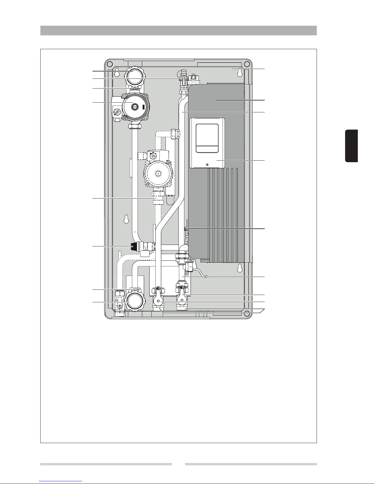
MAIN COMPONENTS
1 Galvanised and internally insulated backplate
2 Ball valve, DN 20 3/4” F – 1” M (primary outlet)
3 Red knob for ball valve with temperature sensor (primary inlet)
4 Blue knob for ball valve with temperature sensor (primary outlet)
5 Pump (primary circuit)
6 Ball valves, DN 20 3/4” F - 1" M (secondary circuit)
7 Red knob for ball valve (DHW outlet)
8 Blue knob for ball valve (cold water inlet)
9 Non-return valve (primary and secondary circuits)
10 Safety valve, 6 bar (secondary circuit)
11 Filling/drain cock, 1/2”
12 Flow meter and temperature sensor (secondary circuit)
13 Brazed, stainless steel, plate heat exchanger
14 Electronic control unit
15 Piping
4
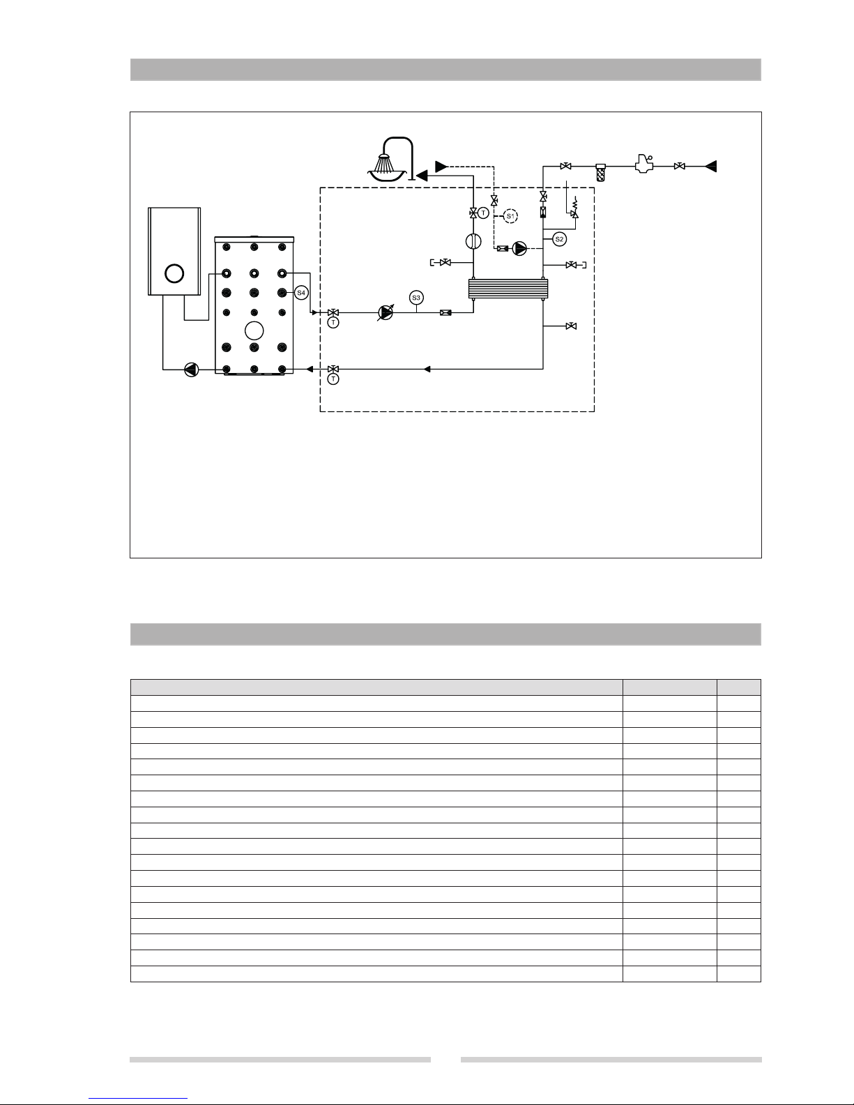
WATER CIRCUIT
TECHNICAL SPECIFICATIONS
EAF
5
9
4
6
6
3
2
1
1
10
1
8
7
8
1 Valve with temperature sensor
2 Modulating pump
3 Heat exchanger
4 Flow meter
5 Valve with temperature sensor
6 Non-return valve
7 Manual bleed valve
8 Manual drain valve
9 Recirculation pump (accessory kit)
10 Safety valve
DESCRIPTION ACS 40 E
Thermal power absorbed with storage cylinder at 50°C and DHW water delivery at 10-45°C 72 kW
Water draw at 10-45°C with storage cylinder at 50°C 29,5 l/min
Thermal power absorbed with storage cylinder at 55°C and DHW water delivery at 10-45°C 94,0 kW
Water draw at 10-45°C with storage cylinder at 55°C 38.5 l/min
Thermal power absorbed with storage cylinder at 60°C and DHW water delivery at 10-40°C 92 kW
Water draw at 10-40°C with storage cylinder at 60°C 44 l/min
Maximum flow-rate primary 1850 l/h
Minimum permissible temperature, DHW circuit 2 °C
Maximum operating temperature 90 °C
Maximum operating pressure, primary circuit 10 bar
Opening pressure, primary circuit non-return valves 28 mbar
Opening pressure, DHW circuit non-return valves 28 mbar
Consumption 47 W
Power supply voltage 230 V
Power supply frequency 50-60 Hz
Index of protection 40 IP
Net weight 19,2 kg
Water capacity 6,6 l

5
ENGLISH
Domestic hot water production graph
NB: Correct functioning of the product is only guaranteed if the primary circuit inlet temperature is at least 5°C higher
than the DHW setpoint.
CHARACTERISTIC CURVES FOR PRIMARY CIRCUIT PUMPS
00,5 1,01,5 2,02,5 3,0
00,2 0,40,6 0,8
0246810
0
1
2
3
4
5
6
7
0
10
20
30
40
50
60
70
00,5 1,01,5 2,02,5 3,0
0
20
40
3695/ 25
PWM1
4178/ 15
PWM1
4660/ ≤5
PWM1
3213/ 35
PWM1
2730/ 45
PWM1
2248/ 55
PWM1
1765/ 65
PWM1
1283/ 75
PWM1
800/ 85
PWM1
p/kPa
H/m
P
1
/W
Q/m³/ h
Q/l/s
Q/Igpm
Q/m³/ h
max.
max.
Wilo-Yonos Para RS
15/7.0, 20/7.0, 25/6, 30/7.0
1-230 V - Rp1/2, Rp3/4, Rp1, Rp1 1/4
n=1/min/ % PWM 1
45
40
40 45 50 55 60 65 70 75 80 85
35
30
25
20
Produzione ACS (l/min
)
Mandata primario (°C)
10÷42 °C
10÷45 °C
10÷48 °C
10÷50 °C
10÷55 °C
10÷60 °C
10÷65 °C
Primary inlet (°C)
DHW ow rate (l/min)
00,5 1,01,5 2,02,5 3,0
00,2 0,40,6 0,8
0246810
0
1
2
3
4
5
6
7
0
10
20
30
40
50
60
70
00,5 1,01,5 2,02,5 3,0
0
20
40
800 1/min
2390 1/min
3400 1/min
4660 1/min
max.
p/kPa
H/m
P
1
/W
Q/m³/ h
Q/l/s
Q/Igpm
Q/m³/ h
max.
Wilo-Yonos Para RS
15/7.0, 25/7.0, 30/7.0
1-230 V - Rp1/2, Rp1, Rp1 1/4
6
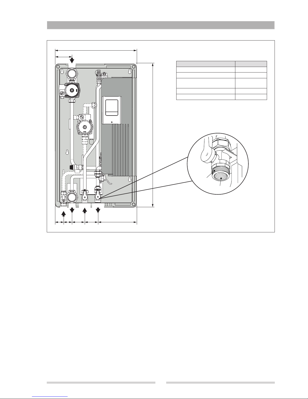
DIMENSIONS AND FITTINGS
MP
RS
RP EAFS UACS
480
100
807555 45 225
840
ACS 40 E
MP - Primary inlet 1 M - 3/4" F
RP - Primary outlet (return) 1 M - 3/4" F
EAFS - Domestic cold water
inlet
1 M - 3/4" F
UACS - DHW outlet 1 M - 3/4" F
RS - Recirculation union 3/4” M
1” M
3/4” F
7
ENGLISH
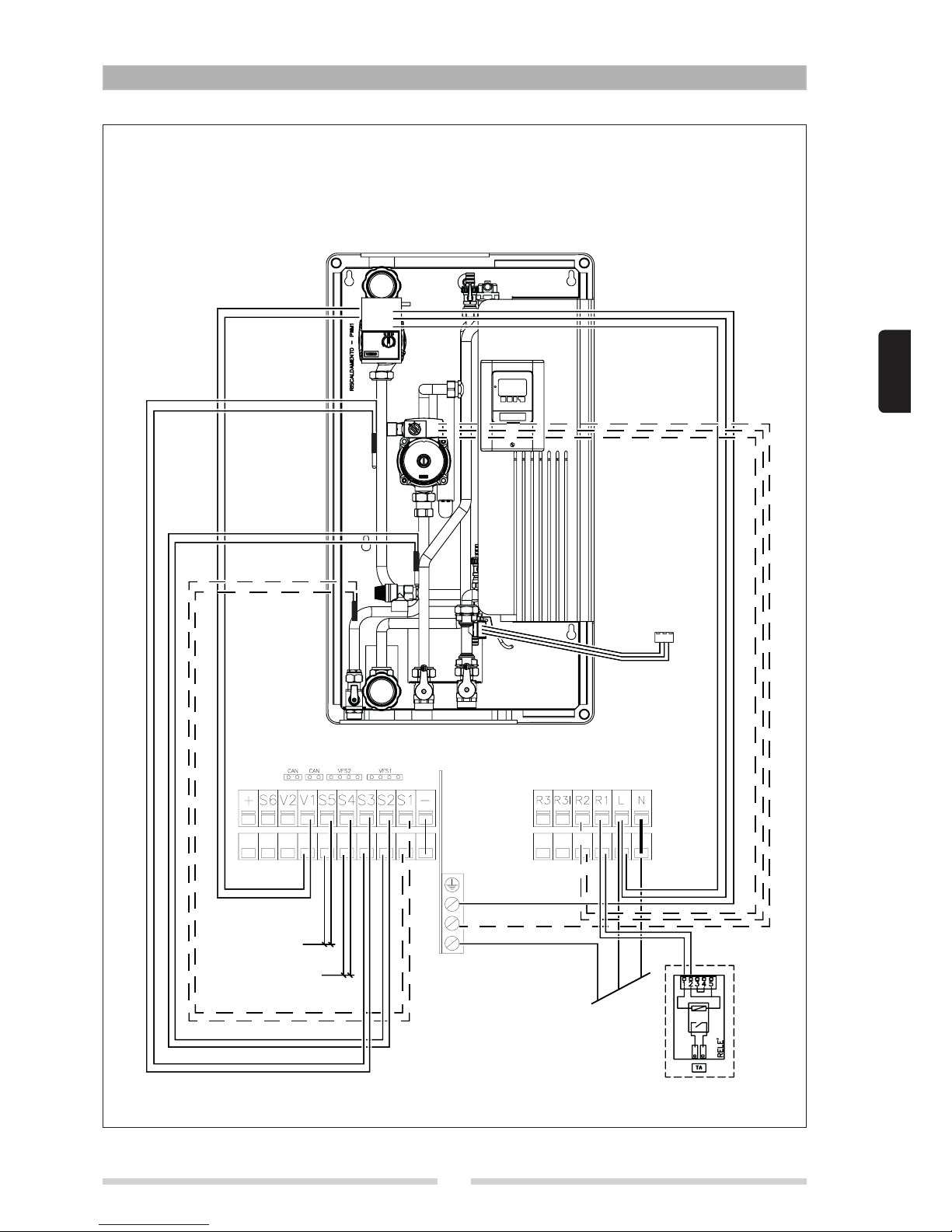
WIRING DIAGRAM
S5
S4
(*)
LATO SONDE E CONTROLLO LATO ALIMENTAZIONE 230 V
SENSOR AND CONTROL
TERMINALS 230 V POWER TERMINALS
S4 Storage cylinder top sensor
S5 Storage cylinder bottom sensor
(*) Connect to controller terminal VFS1
8
PRELIMINARY CHECKS
Carefully remove the packing and check that the product is complete and undamaged. If any defect or damage is detected, do not install or attempt to repair the product but return it to the retailer. Dispose of packaging in compliance with
applicable law.
b
Make sure that the installation position provides easy visibility of and access to the safety valves.
b
Connect the safety valves to a drain in conformity to applicable standards.
b
Install the product as near as practical to the storage cylinder. The product is designed to work with a pipe length
of 4 metres (inlet and return) between itself and the storage cylinder.
b
Disconnect the product from the mains power supply before commencing any work on it.
b
The product must be installed in conformity to the laws and standards applicable in the country of installation.
b
The manufacturer’s responsibility ends with the supply of the product. The product must be installed in conformity
to applicable standards by suitably qualified persons employed by a company that assumes full responsibility for
the completed installation.
INSTALLATION AND PUTTING INTO SERVICE
Bear in mind the following before installing the product:
- The product is designed to mix domestic hot water from a storage cylinder. Any other use, or any use incompatible with
the product’s technical specifications, is considered improper. Do not connect the product directly to a boiler.
- The product is not designed to be operated by children or persons with limited physical, psychological, sensorial or
mental capacities.
- If the piping needed to connect the product to the water system is damaged, it must be replaced by a suitably qualified
person.
- The installation must comply with all applicable laws and standards.
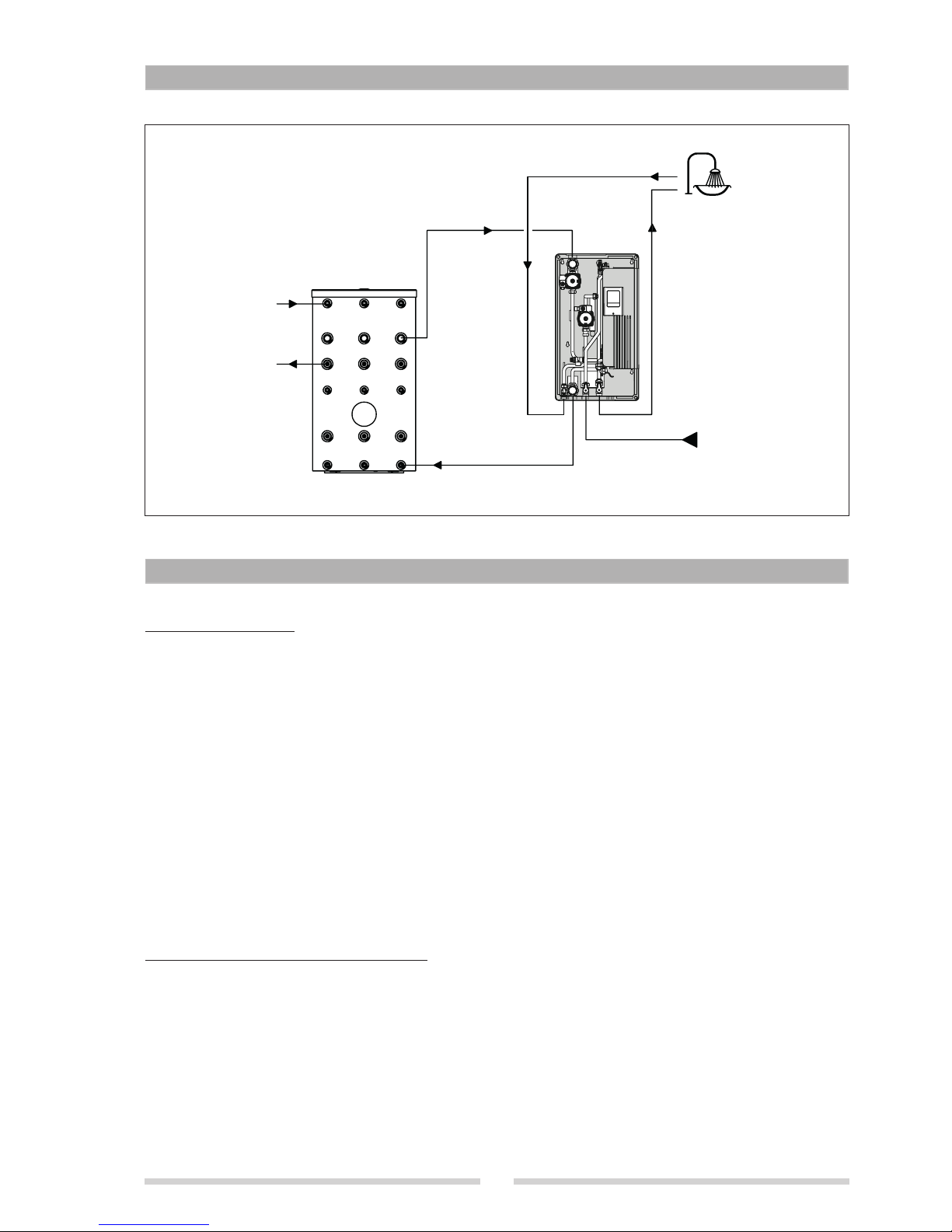
SYSTEM SCHEMATIC
INSTALLATION
Example of wall mounted installation
Boiler
DHW outlet
Recirculation
Cold water inlet
Primary outlet (return)
Primary inlet
9
ENGLISH
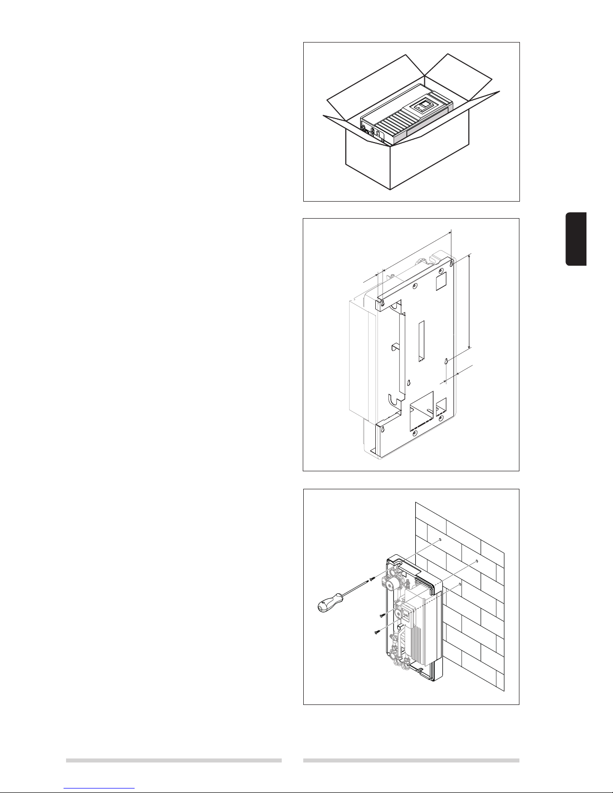
394
15
45
495
b
Installation and connection of the product must be
performed by an authorised, specialist company.
The company installing the product assumes all
responsibility for ensuring that the installation and
functioning of the product conform to applicable
standards.
b
The product must be stored in a dry place where it
is not subject to frost. The product must be installed
where it is protected against splashes of water. Ambient temperature in the place of installation must
not exceed 40°C during functioning of the product.
b
It is advisable to install the product as near as practically possible to the storage cylinder, in order to
avoid unnecessary heat loss from the connecting
pipes.
b
Handle with care!
- Remove the product from its packaging and remove the
polypropylene cover.
- Drill the wall at the positions shown in the figure and fit
three 12 mm wall plugs. Mount the product on the wall,
inserting the wall plugs through the slots in the rear. Slide the product down until the screws lie at the top of
the slots.
- Tighten the screws on the metal backplate through the
holes in the front of the product as shown in the figure.
- Connect the water pipes according to the schematic in
“System schematic”.
- Check that all connections have been made correctly.
Make sure that the entire system is water tight before
putting the mixer into service. To ensure maximum efficiency, also make sure that all air has been bled from
the system.
- Fit the cover.
 Loading...