


ACQUAHOME 25 B - 25 BS
USER MANUAL

2
ENGLISH
Dear Customer,
Thank you for preferring a T heating unit, a modern,
high-quality product that is able to guarantee your maximum
well-being for a long period of time, with high levels of reliability
and safety. In particular, if working together with a Technical
Assistance Centre T that is specifically prepared
and trained to perform periodic maintenance, your unit will
remain at maximum efficiency levels at minimum operating
costs and if required, replacements with original spare parts
can be made.
This instruction manual contains important instructions and
precautions that must be observed to ensure the trouble-free
installation and efficient functioning of your
ACQUAHOME 25
B - 25 BS
boiler.
Please accept our renewed thanks for your purchase.
Thermital
CONFORMITY
ACQUAHOME 25 B - 25 BS
boilers conform to the following di-
rectives:
- Directive 92/42/EEC on efficiency requirements
- Electromagnetic Compatibility Directive 2014/30/UE
- Low Voltage Directive 2014/35/UE
- Ecodesign Directive 2009/125/CE for energy-related
products
- Energy Labelling Directive 2010/30/EU
- Delegated Regulation (EU) N. 811/2013
- Delegated Regulation (EU) N. 813/2013
- Delegated Regulation (EU) N. 814/2013
ENGLISH

This manual, Code 20112806 - Rev. 2 (05/17) comprises 20 pages.
3
ENGLISH
CONTENTS
The following symbols are used in this manual:
b
CAUTION! =
Identifies actions that require caution and
adequate preparation.
a
STOP! =
Identifies actions that you MUST NOT do.
This manual, Code
- Rev.
comprises
pages.
GENERAL INFORMATION .................... 4
General Safety Information.......................... 4
Precautions...................................... 4
Description of the appliance ........................ 5
Safety devices ................................... 5
System layout .................................... 6
Control panel ....................................8
Electronic control unit.............................. 9
Navigation scheme............................... 10
USE ..................................... 11
Putting into service...............................11
Preliminary operations ............................ 11
Start-up........................................ 11
Ignition failure...................................12
Resetting the burner and safety thermostat............12
Menu settings...................................13
Temporary shutdown ............................. 15
Preparing for extended periods of disuse .............15
Cleaning and servicing the boiler ................... 16
External cleaning ................................ 16
Annual cleaning ................................. 16
Troubleshooting .................................18
RECYCLING AND DISPOSAL ................ 18

4
ENGLISH
GENERAL INFORMATION
General Safety Information
b
Check that the product is complete, undamaged
and as ordered as soon as you receive it. Report any
discrepancies or damage to the
T dealer
who sold it.
b
This product must be installed by a legally qualified
heating engineer. On completion of the installation,
the installer must issue the owner with a declaration
of conformity confirming that the installation has been
completed to the highest standards in compliance
with the instructions provided by T in this
instruction manual, and that it conforms to all applicable
laws and standards.
b
This product must only be used for the purpose for which
it is designed and made, as specified by T.
T declines all responsibility, contractual or
other, for damage to property or injury to persons or
animals caused by improper installation, adjustment,
maintenance or use.
b
The room where the boiler is installed must be properly
ventilated to ensure a sufficient supply of air for correct
combustion.
b
If you notice any water leaks, disconnect the boiler from
the mains electricity supply and shut off the water supply.
b
The boiler must be serviced at least once a year.
b
Periodically check that pressure in the central heating
circuit, when cold, is approximately 1.5 bar and below
the maximum limit specified for the boiler.
b
If the boiler is not going to be used for an extended
period of time, perform the operations described later in
this manual.
b
This manual is an integral part of the equipment and
therefore must be stored carefully and must ALWAYS
accompany the boiler even if it is sold to another Owner
or User or transferred to another plant. If it is damaged
or lost, request another copy from your local Technical
Assistance Centre
T.
Precautions
The operation of any appliance that uses fuel, electrical power
and water demands that a number of fundamental safety
precautions be respected:
a
Do not allow children or infirm persons to operate the
system unsupervised.
a
It is forbidden to use electrical devices or equipment,
such as switches, appliances, etc. if there is a smell of
gas or un-burnt products. If so:
- Ventilate the room, opening doors and windows
- Close the fuel shut-off cock.
a
Do not touch the boiler while barefoot or wet.
a
Never clean or service the boiler without first disconnecting
it from the mains electricity supply by turning the mains
power switch and the control panel switch OFF.
a
Do not tamper with or adjust the safety or control devices
without prior authorisation and instructions from the
manufacturer.
a
Never pull, disconnect, or twist the electrical cables
coming from the appliance even if it is disconnected
from the mains electricity supply.
a
Do not obstruct or restrict the vents in the room where
the boiler is installed. Adequate ventilation is essential for
correct combustion.
a
Do not expose the boiler to the elements. It is not
designed for use outdoors.
a
It is prohibited to leave inflammable substances and
containers in the room where the boiler is installed.
a
Do not dispose of packaging material into the
environment, or leave it within the reach of children, since
it can become a potential hazard. Dispose of packaging
material in compliance with applicable legislation.
a
It is forbidden to operate the boiler without water.

5
ENGLISH
Description of the appliance
The
ACQUAHOME 25 B - 25 BS
boiler produces hot water for
central heating and also produces domestic hot water in an
integrated 60 litre storage cylinder.
It can function at low temperature and is oil fuelled.
The single stage oil burner has a vertical steel combustion
chamber.
Model
ACQUAHOME 25 BS
(unlike model
ACQUAHOME 25 B
)
has a sealed chamber.
The boiler body is thoroughly and effectively insulated with a
layer of high density glass wool.
The
ACQUAHOME 25 B - 25 BS
boiler's control logic incorporates
a total shutdown function to minimise energy consumption:
- In "Summer" mode ("Summer/Winter" selector turned to
Summer position), the burner only starts up to restore
the setpoint temperature of the water in the storage
cylinder. In "Winter" mode ("Summer/Winter" selector
turned to Winter position), the burner starts up either in
response to a request for heat from the heating system
(i.e. when the room thermostat switches the heating on)
or to restore the setpoint temperature of the water in
the storage cylinder (DHW heat requests are prioritised
over central heating requests).
Safety devices
ACQUAHOME 25 B - 25 BS
boilers incorporate the following
safety and control devices:
-
A manual reset safety thermostat
that forces a safety shutdown if boiler temperature exceeds the safety
threshold (100°C). The sensor used to monitor this temperature is located on the body of the heat exchanger;
-
Sensors
that measure the temperature of the boiler and
storage cylinder;
-
An electronic burner controller
that monitors the correct
functioning of the selected burner program and sends
a lockout signal to the control panel in the event of an
error.
b
The intervention of a safety device indicates a potentially
dangerous malfunction in the system. Contact the
manufacturer’s Technical Assistance Centre immediately.
b
Safety devices must only be replaced by the
manufacturer's Technical Assistance Centre using
original spare parts. Refer to the spare parts catalogue
supplied with the boiler.
a
Do not use the boiler if any of its safety devices are faulty.
Always check that the boiler is functioning correctly after
repairs have been made.
6
ENGLISH
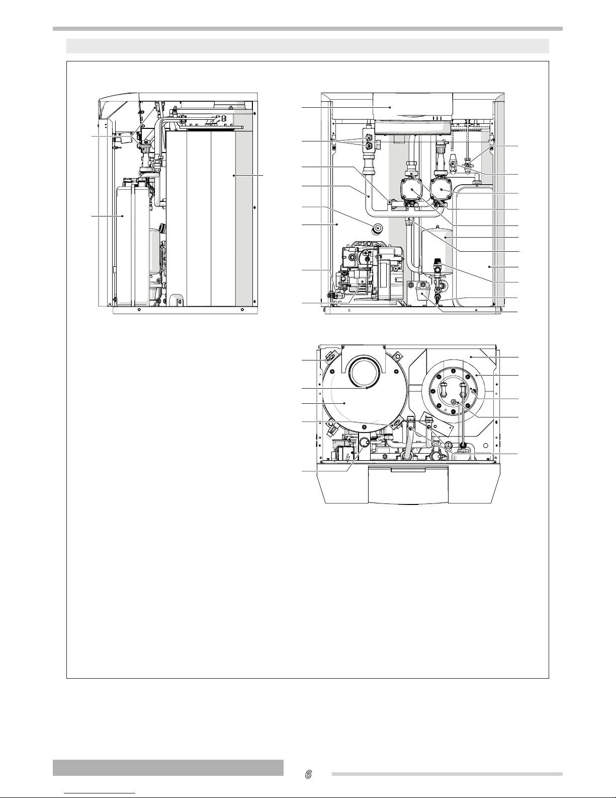
System layout
ACQUAHOME 25 B
6
8
7
5
4
1
2
9
11
10
23
21
22
23
1
17
18
15
19
20
14
2
16
3
27
3
26
25
12
13
24
15
1
Automatic bleed valve
2
Central heating circuit expansion
vessel
3
Storage cylinder with insulation
4
Control panel
5
Sensor sockets
6
Capillary pressure gauge fitting
7
Distribution manifold
8
Flame inspection window
9
Boiler body
10
Boiler drain cock
11
Burner
12
Fuel oil filter
13
Storage cylinder drain cock
14
Storage cylinder safety valve
15
Non-return valve
16
Storage cylinder expansion vessel
17
Central heating circuit pump
18
Boiler circulator
19
Central heating circuit safety valve
20
Storage cylinder fill cock
21
Flue gas exhaust fitting
22
Flue gas box cover
23
Lifting bracket
24
Manual air vent valve
25
Storage cylinder sensor socket
26
Storage cylinder inspection flange
27
Storage cylinder flange insulation

7
ENGLISH
ACQUAHOME 25 BS
6
8
7
5
4
1
2
9
10
12
11
18
19
16
20
21
15
2
17
3
29
30
3
13
14
27
16
28
22
23
24
25
26
1
1
Automatic bleed valve
2
Central heating circuit expansion vessel
3
Storage cylinder with insulation
4
Control panel
5
Sensor sockets
6
Capillary pressure gauge fitting
7
Distribution manifold
8
Flame inspection window
9
Boiler body
10
Air intake obstructed
11
Boiler drain cock
12
Burner
13
Fuel oil filter
14
Storage cylinder drain cock
15
Storage cylinder safety valve
16
Non-return valve
17
Storage cylinder expansion vessel
18
Central heating circuit pump
19
Boiler circulator
20
Central heating circuit safety valve
21
Storage cylinder fill cock
22
Air intake fitting
23
Flue gas exhaust fitting
24
Flue gas box cover
25
Air box
26
Lifting bracket
27
Manual air vent valve
28
Storage cylinder sensor socket
29
Storage cylinder inspection flange
30
Storage cylinder flange insulation

8
ENGLISH
Control panel
ACQUAHOME 25 B - 25 BS
2 31
8
7 56 4
1 Function selector
Off
On
Burner reset
2 Electronic control unit
3 Boiler pressure gauge
Displays the pressure in the central heating circuit
4 Fuse holder
Holds the protective fuse 6.3 A-T
5 Indicator showing a burner lockout for a tripped safety thermostat (red)
Lights to show that the safety thermostat has tripped
6 Burner lockout indicator (red)
Lights to show that the burner locked out
7 Electrical power indicator (green)
Lights to show that the boiler is receiving electrical power
8 Manual reset for safety thermostat
Allows you to reset the boiler if the safety thermostat trips. Unscrew the protective cover to
access the reset button

9
ENGLISH
Electronic control unit
The electronic controller provides the interface by means of which the installer and user can set and change functioning
parameters and view boiler status.
The electronic controller lets you:
- Change the functioning mode;
- View the temperature of the boiler and storage cylinder;
- Change the boiler and storage cylinder parameters (password required);
- view alarms.
T3D P1 T4T1T2 S1 S2 P
S3
S4 S5TR S6
T1 Storage cylinder parameter selection / setting key
T2 Boiler parameter selection / setting key
T3 Value increase button
T4 Value decrease button
S1 Storage cylinder temperature / setpoint indicator (yellow)
S2 Boiler temperature / setpoint indicator (yellow)
S3 Service/error indicator (red)
S4 Stand-by mode indicator (green)
S5 Summer mode indicator (green)
S6 Winter mode indicator (green)
TR Mode selection key
D Three digit display
P Parameter index point
P1 “10,000 hours/starts” indicator points
Right decimal point only: value = 10000
Central decimal point only: value = 20000
Central decimal point + right decimal point: value = 30000
≥ 900 ore
≤ 999 ore
≥ 9900 ore
≤ 9999 ore
≥ 19900 ore
≤ 19999 ore
≥ 29900 ore
≤ 29999 ore
≥ 39900 ore
≤ 39999 ore

10
ENGLISH
Navigation scheme
Displaying and changing storage cylinder settings
Displaying and changing boiler settings
+
Displaying hours remaining to the next service

11
ENGLISH
USE
Putting into service
Have the T Technical Assistance Service start up
your
ACQUAHOME 25 B - 25 BS
boiler for the first time. Once this
has been done, the boiler can be left to function automatically.
Under certain circumstances, such as after long periods of
disuse, the user may need to re-start it without involving the
Technical Assistance Centre.
Preliminary operations
Perform the following checks before starting up the boiler:
- Check that the fuel shut-off cock and heating system
shut-off cock are open
- check that the central heating circuit pressure gauge
shows a pressure over
1,5 bar
with the system cold.
Check also that the circuit is properly de-aerated
Start-up
Once you have completed all the checks listed above, proceed
as follows to start up the boiler for the first time:
- Turn the boiler’s mains power switch ON
- Set the room thermostat to the required temperature (~
20°C) or, if the system has a timer or timer-thermostat,
make sure that this is switched “ON” and adjusted to
the required temperature (~ 20°C).;
- Open the control panel access door;
- Set boiler temperature to 75°C and storage cylinder
temperature to 50°C as instructed in the relevant parts
of the "Menu settings" section;
- Turn the function selector to "ON" and make sure that
the green power indicator lights;
- Press the mode key to set the desired functioning mode
(Summer or Winter);
The burner only starts up at the end of the fuel oil pre-heating
phase.
The boiler now starts up and the burner remains lit until the
temperature setpoint is reached.

12
ENGLISH
Ignition failure
If any ignition errors or malfunctions occur, the burner enters
“LOCKOUT”. This is shown by the red button light on the
burner and by the warning light on the control panel.
b
If a “LOCKOUT SHUTDOWN” occurs, wait about 30
seconds before resetting the burner.
Resetting the burner and safety thermostat
To restore normal startup conditions, open the cover of the
control panel and turn the function selector to
"Reset burner"
for at least 1 second before returning it to its original position.
Wait for the burner to complete the entire ignition cycle again,
up to the ignition of the flame.
If boiler temperature becomes too high, the manual reset
safety thermostat trips.
b
If the safety thermostat trips (T>100°C), the warning light
on the control panel comes on
Proceed as follows to reset the safety thermostat.
- Wait until boiler temperature falls below 80°C.
- Remove the safety thermostat cover.
- Press the manual reset button.
- Wait for the complete ignition cycle to be repeated and
for the flame to ignite.
b
Eliminate the cause of the overheating before restarting
the boiler. Contact T’s Technical Assistance
Service.

13
ENGLISH
Menu settings
TEMPERATURE DISPLAY
Storage cylinder temperature display
Press the key to display storage cylinder temperature.
The indicator in the key itself shows steady light. Temperature
is expressed in degrees centigrade. The display can show
values between 110°C and 10°C. The mode indicators show
the current functioning mode and burner state. The display
automatically returns to showing boiler temperature after 2
seconds.
Boiler temperature display
To view boiler temperature, press the key.
The indicator in the key itself shows steady light. Temperature
is expressed in degrees centigrade. The display can show
values between 110°C and 10°C. The mode indicators show
the current functioning mode and burner state.
b
If no key is pressed for two minutes, the system enters
“low consumption” mode and the central section of the
display flashes. Pressing any key restores the boiler
temperature display.
CHANGING THE FUNCTIONING MODE
You can only change the boiler’s functioning mode when
the display is reading out either boiler or storage cylinder
temperature. Press the "mode key" repeatedly to scroll to the
required functioning mode. The default setting is "Winter".
- In stand-by mode (with the indicator lit) the boiler
remains off unless settings activate the anti-frost or antilegionella function (if enabled)
- In summer mode (with the indicator lit) the boiler
responds only to requests for domestic hot water.
The central heating system is switched off. This mode
indicator is continuously lit if the burner is running and
flashes if the burner is shut down.
- In winter mode (with the indicator lit) the boiler
responds to heat requests from the domestic hot water
and central heating systems. This mode indicator is
continuously lit if the burner is running and flashes if the
burner is shut down.

14
ENGLISH
DISPLAYING AND CHANGING BOILER
AND STORAGE CYLINDER SETPOINTS
Displaying and changing the boiler setpoint
Press the key to display boiler temperature.
If you press the or key while the boiler temperature is
displayed, the indicator starts to flash and the boiler's current
setpoint is shown on the three digit display. The default value is
75°C. Pressing the
or key once more changes the value.
Press the key to confirm the setpoint and return to the boiler
temperature display. The indicator stops flashing.
Displaying and changing the storage cylinder setpoint
Press the key to display storage cylinder temperature.
If you press the or key while the storage cylinder
temperature is displayed, the
indicator starts to flash and
the storage cylinder's current setpoint is shown on the three
digit display. The default value is 50°C. Pressing the
or
key once more changes the value.
Press the key to confirm the setpoint and return to the storage
cylinder temperature display. The indicator stops flashing.

15
ENGLISH
Temporary shutdown
To switch the boiler off for short periods with outdoor
temperature ABOVE ZERO:
- Open the control panel access door;
- Turn the function selector to
"ON";
- Press the electronic controller's "mode key" to select
STAND-BY mode ( );
b
The boiler has a FROST PROTECTION FUNCTION that
switches on the burner and the pumps if there is a risk
of freezing.
Preparing for extended periods of disuse
If the boiler is not going to be used for an extended period of
time, proceed as follows to prepare it for shut-down
- Open the control panel access door;
- Turn the main power switch to
"OFF" and make sure
that the green power indicator goes out;
- switch the boiler OFF at the mains power switch;
- Close the boiler’s fuel cock and water supply cock.
b
Drain the central heating circuit and domestic hot water
circuit if there is any risk of freezing.

16
ENGLISH
Cleaning and servicing the boiler
Please remember that THE PERSON RESPONSIBLE
FOR SYSTEM MANAGEMENT MUST ENSURE THAT
PROFESSIONALLY QUALIFIED HEATING ENGINEERS
UNDERTAKE PERIODIC MAINTENANCE AND COMBUSTION
EFFICIENCY MEASUREMENTS.
T’s Technical Assistance Centre is qualified to
satisfy these legal requirements and can also provide useful
information on MAINTENANCE PROGRAMMES designed to
guarantee:
- greater safety
- compliance with applicable legislation
- freedom from the risk of fines in the event of spot
checks.
Regular maintenance is essential for the safety, efficiency and
durability of the boiler.
Servicing is a legal requirement and must be performed at least
once a year by a professionally qualified heating engineer.
External cleaning
Clean the boiler’s casing panels and control panel with a soft
cloth damped in soapy water.
To remove marks from the boiler casing, use a cloth damped
in a 50% mix of water and denatured alcohol or a suitable
cleaning product.
Wipe the boiler dry after cleaning it.
a
Do not use abrasive products, petrol or triethylene.
Annual cleaning
At least once a year, the user must have the boiler served by
T's Technical Assistance Service or by a qualified
heating engineer.

17
ENGLISH
SYSTEM ERRORS AND ALARMS
Alarm Description
AL1
This message on the three digit display indicates an active burner lockout alarm. The
indicator shows steady
light.
AL2
This message on the three digit display indicates an active safety temperature alarm (safety thermostat
tripped). The
indicator shows steady light.
AL6
This message on the three digit display indicates a malfunction (short circuit) of the storage cylinder sensor.
The
indicator shows steady light.If no storage cylinder sensor is detected, the storage cylinder is assumed
to be disabled; for this reason not alarm is generated. If you try to view the value on the display, only “- - -”
appears.
AL7
This alarm on the three digit display indicates a boiler sensor malfunction (sensor failure or short circuit).The
indicator shows steady light.
SEr
Service threshold near warning
When the burner reaches 90% of the operating hours set in boiler parameter P7 (see Programming
Parameters), the three figure display reads out the message “SEr” for about three seconds every time the
burner starts (unless the display is in low consumption mode).
Service threshold passed warning
If the burner’s operating hours reach or exceed the value set in boiler parameter P7 (see Programming
Parameters), the
indicator flashes to show that the burner requires service. The three figure display reads
out the message “SEr” for about three seconds every time the burner starts (unless the display is in low
consumption mode).
Displaying the hours left before service is needed
Press the and keys simultaneously to read out on the 3 figure display how many hours of operation are left
before the service threshold is reached (max 999).

18
ENGLISH
Troubleshooting
FAULT CAUSE SOLUTION
There is a smell of fumes Fumes escaping into the air
- Contact your local Technical
Assistance Centre
The generator is at temperature but
the heating system is cold
Air in the circuit
- Contact your local Technical
Assistance Centre
Pump malfunctioning
- Contact your local Technical
Assistance Centre
The boiler does not reach its
temperature setpoint
Boiler dirty
- Contact your local Technical
Assistance Centre
Burner capacity insufficient
- Contact your local Technical
Assistance Centre
Problem with boiler control card
- Contact your local Technical
Assistance Centre
The generator triggers a thermal
safety block
Problem with boiler control thermostat
- Contact your local Technical
Assistance Centre
No water
- Contact your local Technical
Assistance Centre
The safety valve keeps opening
Incorrect central heating circuit pressure
- Contact your local Technical
Assistance Centre
CH expansion vessel
- Contact your local Technical
Assistance Centre
The central heating pump is not
working
Pump seized
Electrical connections
- Contact your local Technical
Assistance Centre
No heat request from
- Contact your local Technical
Assistance Centre
RECYCLING AND DISPOSAL
Packaging materials from T
ACQUAHOME 25 B - 25
BS
boilers must be disposed of through appropriate channels
in order to permit recovery and recycling. At the end of its
useful life, dispose of the boiler in compliance with applicable
legislation.

19
ENGLISH

20112806 - Rev. 2 (05/17)
RIELLO S.p.A.
Via Ing. Pilade Riello, 7
37045 - Legnago (VR)
www.thermital.it
The manufacturer strives to continuously improve all products. Appearance, dimensions, technical
specications, standard equipment and accessories are therefore liable to modication without
notice.
 Loading...