

ACQUAHOME 25 B BLU
USER MANUAL

2
ENGLISH
Dear Customer,
Thank you for preferring a T heating unit, a modern, high-quality product that is able to guarantee your maximum well-being for a long period of time, with high levels of
reliability and safety. In particular, if working together with a
Technical Assistance Centre T that is specifically
prepared and trained to perform periodic maintenance, your
unit will remain at maximum efficiency levels at minimum operating costs and if required, replacements with original spare
parts can be made.
This instruction manual contains important instructions and
precautions that must be observed to ensure the trouble-free
installation and efficient functioning of your
ACQUAHOME 25 B
BLU
boiler.
Please accept our renewed thanks for your purchase
Thermital
CONFORMITY
ACQUAHOME 25 B BLU
boilers conform to the following direc-
tives:
- Directive 92/42/EEC on efficiency requirements
- Electromagnetic Compatibility Directive 2014/30/EU
- Low Voltage Directive 2014/35/EU
- Ecodesign Directive 2009/125/CE for energy-related
products
- Energy Labelling Directive 2010/30/EU
- Delegated Regulation (EU) N. 811/2013
- Delegated Regulation (EU) N. 813/2013
- Delegated Regulation (EU) N. 814/2013
ENGLISH

This manual, Code 20129620 - Rev. 0 (07/18) comprises 20 pages.
3
ENGLISH
CONTENTS
The following symbols are used in this manual:
b
CAUTION! =
Identifies actions that require caution and
adequate preparation.
a
STOP! =
Identifies actions that you MUST NOT do.
This manual, Code
- Rev.
comprises
pages.
GENERAL INFORMATION . . . . . . . . . . . . . . . . . . . . 4
General Safety Information. . . . . . . . . . . . . . . . . . . . . . . . . . 4
Precautions. . . . . . . . . . . . . . . . . . . . . . . . . . . . . . . . . . . . . . 4
Description of the appliance . . . . . . . . . . . . . . . . . . . . . . . . 5
Safety and control devices. . . . . . . . . . . . . . . . . . . . . . . . . . 5
System layout . . . . . . . . . . . . . . . . . . . . . . . . . . . . . . . . . . . . 6
Control panel . . . . . . . . . . . . . . . . . . . . . . . . . . . . . . . . . . . . 7
Menu navigation. . . . . . . . . . . . . . . . . . . . . . . . . . . . . . . . . . 9
Navigation scheme. . . . . . . . . . . . . . . . . . . . . . . . . . . . . . . 11
List of user parameters. . . . . . . . . . . . . . . . . . . . . . . . . . . . 12
USE . . . . . . . . . . . . . . . . . . . . . . . . . . . . . . . . . . . . . 14
Putting into service. . . . . . . . . . . . . . . . . . . . . . . . . . . . . . . 14
Preliminary operations . . . . . . . . . . . . . . . . . . . . . . . . . . . . 14
Start-up. . . . . . . . . . . . . . . . . . . . . . . . . . . . . . . . . . . . . . . . 14
Adjustment of heating setpoint. . . . . . . . . . . . . . . . . . . . . . 15
Enable/disable the heating function. . . . . . . . . . . . . . . . . . 15
Adjustment of domestic setpoint . . . . . . . . . . . . . . . . . . . . 15
Enable/disable the domestic function . . . . . . . . . . . . . . . . 15
Special functions . . . . . . . . . . . . . . . . . . . . . . . . . . . . . . . . 16
Ignition failure. . . . . . . . . . . . . . . . . . . . . . . . . . . . . . . . . . . 16
Temporary or short-term shut-down . . . . . . . . . . . . . . . . . . 17
Preparing for extended periods of disuse . . . . . . . . . . . . . 17
Device cleaning and maintenance. . . . . . . . . . . . . . . . . . . 17
External cleaning . . . . . . . . . . . . . . . . . . . . . . . . . . . . . . . . 17
Annual cleaning . . . . . . . . . . . . . . . . . . . . . . . . . . . . . . . . . 17
Troubleshooting . . . . . . . . . . . . . . . . . . . . . . . . . . . . . . . . . 18
RECYCLING AND DISPOSAL . . . . . . . . . . . . . . . . 18

4
ENGLISH
GENERAL INFORMATION
General Safety Information
b
This product must be installed by a legally qualified heating engineer. On completion of the installation, the installer must issue the owner with a declaration of conformity
confirming that the installation has been completed to
the highest standards in compliance with the instructions
provided by
T in this instruction manual, and
that it conforms to all applicable laws and standards.
b
This product must only be used for the purpose for which
it is designed and made, as specified by T.
T declines all responsibility, contractual or
other, for damage to property or injury to persons or animals caused by improper installation, adjustment, maintenance or use.
b
The room where the boiler is installed must be properly
ventilated to ensure a sufficient supply of air for correct
combustion.
b
If you notice any water leaks, disconnect the boiler from
the mains electricity supply and shut off the water supply.
b
In case of water leaks disconnect the equipment from
the power mains, close the water supply and promptly
alert Technical Assistance Centre T or professionally qualified personnel.
b
The boiler must be serviced at least once a year. The
failure to perform annual maintenance work will void the
warranty of the equipment.
b
Periodically check that pressure in the central heating
circuit, when cold, is approximately 1.5 bar and below the maximum limit specified for the boiler. If this is
not the case, contact the Technical Assistance Centre
T or professionally qualified personnel.
b
If the boiler is not going to be used for an extended period of time, perform the operations described later in this
manual.
b
This manual is an integral part of the equipment and
therefore must be stored carefully and must ALWAYS accompany the boiler even if it is sold to another Owner or
User or transferred to another plant. If it is damaged or
lost, request another copy from your local Technical Assistance Centre T.
Precautions
The operation of any appliance that uses fuel, electrical power
and water demands that a number of fundamental safety precautions be respected:
a
Do not allow children or infirm persons to operate the
system unsupervised.
a
It is forbidden to use electrical devices or equipment,
such as switches, appliances, etc. if there is a smell of
gas or un-burnt products. If so:
- Ventilate the room, opening doors and windows
- Close the fuel shut-off cock
- Ask for the prompt intervention of the Technical Assistance Centre
a
Do not touch the boiler while barefoot or wet.
a
Never pull, disconnect, or twist the electrical cables coming from the appliance even if it is disconnected from the
mains electricity supply.
a
Do not obstruct or restrict the vents in the room where
the boiler is installed. Adequate ventilation is essential for
correct combustion.
a
Do not expose the boiler to the elements. It is not designed for use outdoors.
a
It is prohibited to leave inflammable substances and containers in the room where the boiler is installed.
a
Do not dispose of packaging material into the environment, or leave it within the reach of children, since it can
become a potential hazard. Dispose of packaging material in compliance with applicable legislation.
a
It is forbidden to operate the boiler without water.
a
The equipment casing must not be removed by people
without specific qualification and expertise.

5
ENGLISH
Description of the appliance
The thermal unit
ACQUAHOME 25 B BLU
is a hot water generator for the heating of environments and production of domestic
hot water (DHW) by means of a vitrified heater. It can function
at low temperature and is oil fuelled. The low NOx burner features a single-stage operation and a vertical steel combustion
chamber. The boiler unit is effectively and accurately insulated
with a high-density glass wool mat. The control panel includes
a user interface with display and an electronic board for the
thermal unit adjustment and control, which allows to manage
the control and safety devices in compliance with the regulations in force.
Safety and control devices
The control panel, apart from managing the functions of the
thermal unit
ACQUAHOME 25 B BLU
, allows to highlight any
anomaly which may affect its correct operation, ensuring the
thermal unit safety by stopping it and automatically closing the
burner light oil valve.
The burner control and adjustment board is also used to ensure the burner safety by managing its correct operation.
Any anomaly which may affect the generator operation forces
it to stop (lock-out) and is promptly signalled with a numerical
error code on the regulator display.
The following are installed on the water circuit:
-
Safety thermostat
: fitted on the generator body, it intervenes by stopping (permanent error) the thermal unit
if the boiler temperature exceeds the limit threshold of
110°C;
-
Safety valve
: intervenes if the boiler pressure exceeds
the limit threshold of 3 bar;
-
Pressure transducer
: sends a signal to the electronic regulator which views and continually checks the
primary circuit pressure to switch on the generator or
cause it to stop in case of low pressure;
-
Boiler temperature probes (delivery and return)
: immersion probe on the delivery line of the generator is used
by the regulator to view and check the delivery water
temperature and check the correct switching on and off
of the burner based on the programmed setpoint. The
regulator uses the same probe to switch off the generator in case of overtemperature, before the triggering of
the safety thermostat. The contact probe placed on the
return line of the boiler is used by the regulator to view
the return water temperature with which it calculates,
together with the delivery temperature, the temperature
difference between delivery and return (∆t), which allows regulating the modulation of the circulator in heating mode.
-
Domestic circuit temperature probe (heater)
: the immersion probe in the heater is used by the regulator to view
and check the domestic hot water temperature and to
manage the relevant operating parameters (DHW Setpoint, DHW request, etc.).
b
The intervention of a safety device indicates a potentially
dangerous malfunction in the system. Contact the manufacturer’s Technical Assistance Centre immediately.
b
Safety devices must only be replaced by the manufacturer's Technical Assistance Centre using original spare
parts. Refer to the spare parts catalogue supplied with
the boiler. After making the repair, check that the appliance is working properly.
a
The appliance must not be put in service, even temporarily, when tampered safety devices are not in operation or
have been tampered with.
6
ENGLISH
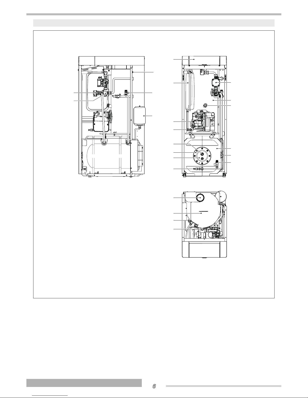
System layout
ACQUAHOME 25 B BLU
7
1
2
8
9
11
10
13
12
20
21
22
23
6
14
16
17
18
19
5
4
3
15
1
Electric actuator
2
3-way diverting valve
3
Main switch
4
Heating safety valve
5
Storage cylinder expansion vessel
6
Control panel
7
Heating expansion reservoir
8
Burner
9
Boiler drain cock
10
Magnesium anode
11
Storage cylinder inspection flange
12
Storage cylinder flange insulation
13
Storage cylinder drain cock
14
Storage cylinder safety valve
15
Storage cylinder fill cock
16
Storage cylinder with insulation
17
Flame inspection window
18
Boiler body
19
Pump
20
Flue gas exhaust fitting
21
Flue gas box cover
22
Lifting bracket
23
Automatic bleed valve

7
ENGLISH
Control panel
Controls interface
5
5
1
2
3
4
6
1
Door
2
Light guide
3
Rear light display
4
ENTER/RESET key: it allows accessing the main menu and restoring the operation after a stop
due to an anomaly
5
Navigation keys
6
Main switch (located on the equipment rear wall)
Light Guide displaying
STAT U S DESCRIPTION
Green blinking
Thermal unit drain cycle and initialization in progress after the power
supply reset.
Steady green Thermal unit on
Steady red Thermal unit in alarm mode
Red blinking Thermal unit in lock-out mode

8
ENGLISH
Display visualisation
HEAT
Bar
Bar
°C
°F
Psi
Psi
OUTSIDE
1 2 3 4 5
6
78
9
10
11
1
Icon displayed when heating mode is enabled. Blinking when there is a heat demand
2
Icon displayed when DHW mode is enabled. Blinking when there is an DHW Demand
3
Icon displayed when entering the "Installer" or "Manufacturer" menu
4
Icon displayed when the burner of the equipment is on. The icon will be marked with a cross in
case of Permanent or Temporary error.
5
Icon displayed when the climatic mode operation is active (Par. 2001= 1 or 2)
6
Celsius/Fahrenheit temperature
7
Displays current value
8
Displaying of system pressure or parameter number or external temperature
9
Icon displayed when the circulator is operating
10
Pressure in Bar/Psi
11
Icon displayed when the outdoor probe is connected

9
ENGLISH
Menu navigation
At start-up or when no key is pressed for more than 4 minutes, the display is in “basic display” mode and provides general information on the equipment operation.
5
3
4
2
1
In this mode, keys have the following functions:
Nr. Button Function
1
"+"
It increases the heating setpoint (when active/available)
2
"-"
It decreases the heating setpoint (when active/available)
3
"▲"
Raise the DHW set point (when available)
4
"▼"
Decrease the DHW set point (when available)
5 "ENTER/RESET"
Enters into "MENU" mode
If pressed for more than 5 seconds, it resets a permanent error (Loc)
Additional functions:
Button Function
"+" with "-" It accesses enable/disable heating function mode
"▲" + "▼"
It accesses enable/disable DHW production function mode
b
For more information, see paragraph "Enable/disable the heating function" on page 15.
"Basic display" mode
Adjustment of heating setpoint
°C
Adjustment of domestic setpoint
°C
or
or or
°C
or

10
ENGLISH
MENU selection
Enters into "MENU" mode when "MENU/RESET" key is pushed. The figures of the small display indicate "0000" which is the first
accessible menu.
5
3
4
2
1
In this mode, keys have the following functions:
Nr. Button Function
1 "+" Exits from the menu and cancels a parameter change
2 "-" Exits from the menu and cancels a parameter change
3
"▲"
Selects the following menu or increases a certain parameter value
4
"▼"
Selects the previous menu or decreases a certain parameter value
5 "ENTER/RESET" Enters into the selected menu/parameter or confirms the parameter change

11
ENGLISH
Navigation scheme
"Basic display" mode
"End user" mode
Bar
°C
or
Example of parameter setting
change
conrmed
change
canceled
or
or or

12
ENGLISH
List of user parameters
Menu
Par.
No.
Description Range
Default set-
ting
UM
Main menu
0000
013
Quick adjustment of direct Zone/Zone 1 heating setpoint in 0 and
3 heating modes.
By connecting the zone control accessory, this parameter can be
used to quickly change direct Zone/Zone 1 setpoint. This parameter simultaneously modifies the value of Par. 2103.
See Par. 2103 See Par. 2103 °C
0000
023
Quick adjustment of Zone 2 heating setpoint in 0 and 3 heating
modes.
By connecting the zone control accessory, this parameter can be
used to quickly change Zone 2 setpoint. This parameter simultaneously modifies the value of Par. 2203.
See Par. 2203 See Par. 2203 °C
0000
033
Quick adjustment of Zone 3 heating setpoint in 0 and 3 heating
modes.
By connecting the zone control accessory, this parameter can be
used to quickly change Zone 3 setpoint. This parameter simultaneously modifies the value of Par. 2303.
See Par. 2303 See Par. 2303 °C
0000
047 Quick adjustment of DHW setpoint with heater See Par. 2047 °C
0000
048 Quick adjustment of DHW setpoint with instant production See Par. 2048 °C
0000
201
Stops the venting function
0 = No action
1 = Stop venting
0…1 0
0000
901
Unit of measurement for temperature
0 = °C
1 = °F
0...1 0
0000
902
Pressure unit of measurement
0 = BAR
1 = PSI
0...1 0
Info menu
1000
1101 Direct Zone/Zone 1 delivery temperature °C
1000
1102 Direct Zone/Zone 1 ambient temperature °C
1000
1201 Zone 2 delivery temperature °C
1000
1202 Zone 2 ambient temperature °C
1000
1301 Zone 3 delivery temperature °C
1000
1302 Zone 3 ambient temperature °C
1000
1001 CH flow temperature °C
1000
1002 Domestic hot water temperature °C
1000
1003 Domestic cold water temperature °C
1000
1004 Outdoor temperature °C
1000
1007 Return temperature °C
1000
1033 System pressure
bar

13
ENGLISH
Menu
Par.
No.
Description Range
Default set-
ting
UM
1000
1032 Error code
1000
1112 Zone 1 heating setpoint °C
1000
1113 Zone 2 heating setpoint °C
1000
1114 Zone 3 heating setpoint °C
1000
1053 Flame failure number
1000
1054 Number of ignitions
1000
1055 Number of failed ignitions
1000
1056 Total hours of operation in heating mode
h
x
10
1000
1057 Total hours of operation in domestic mode
h
x
10
1000
1058 Total hours of operation
h
x
10
1000
1063 Input signal 0-10V V
Direct Zone / Zone 1 Heating Settings
2000
2103
Direct Zone/Zone 1 setpoint in heating mode Par. 2001= 0 and 3
The thermal unit adjustment determines the boiler setpoint in
heating mode, using the highest value among the requests of all
the active zones (Par. 1101, 1201, 1301)
If Zone 1 is configured as mixed, the value set in parameter 1112
will be used as setpoint
If Zone 1 is not
enabled:
(Par. 2121, Par.
2024)
If Zone 1 is ena-
bled:
BT: (Par. 2121, 45)
AT: (Par. 2121,Par.
2024)
70 (AT)
45 (BT)
°C
2000
2130 Parallel shift of direct Zone/Zone 1 climatic curve -10…10 0 °C
Zone 2 Heating Settings
2000
2203
Zone 2 heating setpoint in 0 and 3 heating modes
The thermal unit adjustment determines the boiler setpoint in
heating mode, using the highest value among the requests of all
the active zones (Par. 1101, 1201, 1301)
If Zone 2 is configured as mixed, the value set in parameter 1113
will be used as setpoint.
BT: (Par. 2221, 45)
AT: (Par. 2221,Par.
2024)
70 (AT)
45 (BT)
°C
2000
2230 Parallel shift of direct Zone/Zone 1 climatic curve -10…10 0 °C
Zone 3 Heating Settings
2000
2303
Zone 3 heating setpoint in 0 and 3 heating modes
The thermal unit adjustment determines the boiler setpoint in
heating mode, using the highest value among the requests of all
the active zones (Par. 1101, 1201, 1301)
If Zone 3 is configured as mixed, the value set in parameter 1114
will be used as setpoint.
BT: (Par. 2321, 45)
AT: (Par. 2321,Par.
2024)
70 (AT)
45 (BT)
°C
2000
2330 Parallel shift of direct Zone/Zone 1 climatic curve -10…10 0 °C
DHW settings and system conguration
2000
2047 DHW setpoint with heater 40...65 57 °C
2000
2048 DHW setpoint with instant production 40…70 45 °C

14
ENGLISH
USE
Putting into service
Have the T Technical Assistance Service start up
your
ACQUAHOME 25 B BLU
boiler for the first time. Once this
has been done, the boiler can be left to function automatically.
Under certain circumstances, such as after long periods of
disuse, the user may need to re-start it without involving the
Technical Assistance Centre.
Preliminary operations
Perform the following checks before starting up the boiler:
- Check that the fuel shut-off cock and heating system
shut-off cock are open
- the pressure of the hydraulic circuit, with cold water, is
1.5 bar
(value indicated on the first screen of the control
panel display) and the circuit is not vented
- The thermal unit
ACQUAHOME 25 B BLU
is equipped
with a system load valve located inside the thermal unit
Bar
°C
- close the system load valve.
Start-up
Once you have completed all the checks listed above, proceed as follows to start up the boiler for the first time:
- set the main switch of the system to ON and the main
switch of the equipment to (I).
Once the device is on, the software version number will be
displayed for a few seconds.
Once the initialization phase is complete, the display switches
to “basic display” mode.
In this mode, the main information on the equipment operation
is displayed. The meaning of the different icons displayed is
explained in paragraph Control panel.
The icon
and the heating delivery temperature are displayed, either if the boiler is in stand-by mode or if a temperature request is active (icon
blinking).
To switch off the equipment, set the main switch to “0”.
b
Never power off the appliance before switching the master switch to the "0" position.
b
Never switch off the appliance with the master switch if a
request is active. Always make sure that the appliance is
in stand-by before switching the main switch.
Example of generator stand-by display in heating only
mode (external probe not connected)
Bar
°C
- Set the room thermostat to the required temperature (~
20°C) or, if the system has a timer or timer-thermostat,
make sure that this is switched “ON” and adjusted to
the required temperature (~ 20°C).;

15
ENGLISH
Adjustment of heating setpoint
- Press the key“+” or “-” to display the current value of the
heating temperature setpoint.
°C
- Increase or decrease the setpoint according to the type
of system by using the key “+” of “-”.
- To save the modification made and go back to the initial
screen, wait for 3 seconds or press the key “ENTER/
RESET”.
- Check that the thermal unit starts the ignition phase and
that the display shows the icon
blinking (ambient
heating request) and the icon
.
- The thermal unit ignition phase will start only after the
light oil pre-heating phase will be completed and will
remain active until the set temperature will be reached.
Enable/disable the heating function
- Press the keys “+” and “-” simultaneously for a few seconds;
- The icon
and the current heating mode (ON or OFF)
will blink on the display;
- Press the keys “+” and “–” to select the required mode;
- Press the key “ENTER/RESET” or wait for 3 seconds to
save the modification made and go back to the initial
screen.
Adjustment of domestic setpoint
- Press the key "▲" o "▼" to display the current value of
domestic setpoint.
°C
- Increase or decrease the setpoint by using the key “▲"
o "▼".
- To save the modification made and go back to the initial
screen, press the key “ENTER/RESET”.
Enable/disable the domestic function
- Press the keys "▲" and "▼" simultaneously for a few
seconds;
- The icon
and the current domestic mode (ON or
OFF) will blink on the display;
- Press the keys "▲" and "▼" to select the required mode;
- To save the modification made and go back to the initial
screen, press the key “ENTER/RESET”.

16
ENGLISH
Special functions
When a special function is active, a specific message is shown
on the display of the thermal module control interface.
Frost protection
When the anti-freeze function is active, the message “AFro” is
displayed.
Venting
The function is automatically enabled at the first start-up and at
each reset of the power supply.
During the venting, the circulator is enabled, so that the air
which may be present inside the system circuit can exit through
the automatic drain valve of the thermal module.
The light guide status changes as indicated in the paragraph
Light guide Displaying.
Anti-legionella
The function is automatically enabled at first start-up, at each
reset of the power supply or daily, if necessary.
When the function is active, the message “ALE9” is displayed
beside the heater temperature and the icon
blinks.
The function increases the water temperature inside the heater
up to 65°C and keeps it for 30 minutes.
Once this time has elapsed, the control box normal operation
is restored.
Ignition failure
If an ignition or operating anomaly occurs, the thermal unit display will show a text message (small digit) and a number (large
digit), which vary according to the anomaly detected.
For a detailed description, see the error list.
There are 3 error levels:
- Permanent (Loc)
- Temporary (Err)
- Alerts (AttE)
The section with the large digit will display the error number
and , according to the error / alert, a message which will cyclically blink together with the number.
For a detailed description, see the error list.
Permanent Error
The text “Loc” is displayed together with the permanent er-
ror number. The icon
indicates that the burner is disabled.
The equipment must be manually reset by keeping the key
“ENETER/RESET” pressed.
Temporary Error
The text “Err” is displayed together with the temporary error
number.
The icon
indicates that the burner is disabled.
The lock-out error must be solved.

17
ENGLISH
Warnings
The text “AttE” is displayed together with the alert number.
The equipment is not locked out, but its functions may be limited (according to the alert).
Temporary or short-term shut-down
In the event of temporary or short-term shut-down (e.g. due to
holidays), proceed as follows:
- Remove the power supply by setting the main switch
of the equipment and the main switch of the system to
"OFF".
- If there is a danger of frost, keep the system on. To reduce fuel consumption, set the heating set point to the
minimum allowed value.
Preparing for extended periods of disuse
If the appliance is not going to be used for a long period of
time, the following operations should be carried out:
set the main switch of the system to OFF and the main switch
of the equipment to (0);
- close the fuel cock and heating circuit water cock.
b
Drain the central heating circuit if there is any risk of
freezing.
Device cleaning and maintenance
Please remember that THE PERSON RESPONSIBLE FOR
SYSTEM MANAGEMENT MUST ENSURE THAT PROFESSIONALLY QUALIFIED HEATING ENGINEERS UNDERTAKE
PERIODIC MAINTENANCE AND COMBUSTION EFFICIENCY
MEASUREMENTS.
T’s Technical Assistance Centre is qualified to
satisfy these legal requirements and can also provide useful
information on MAINTENANCE PROGRAMMES designed to
guarantee:
- Greater safety
- Compliance with applicable legislation
- Freedom from the risk of fines in the event of spot
checks.
Regular maintenance is essential for the safety, efficiency and
durability of the boiler.
Servicing is a legal requirement and must be performed at
least once a year by a professionally qualified heating engineer.
External cleaning
Clean the boiler’s casing panels and control panel with a soft
cloth damped in soapy water.
To remove marks from the boiler casing, use a cloth damped in
a 50% mix of water and denatured alcohol or a suitable cleaning product.
Wipe the boiler dry after cleaning it.
a
Do not use abrasive products, petrol or triethylene.
Annual cleaning
At least once a year, the user must have the boiler served by
T's Technical Assistance Service or by a qualified
heating engineer.

18
ENGLISH
Troubleshooting
FAU LT CAUSE SOLUTION
There is a smell of fumes Fumes escaping into the air
- Contact your local Technical Assistance Centre
The generator is at temperature but
the heating system is cold
Air in the circuit
- Contact your local Technical Assistance Centre
Pump malfunctioning
- Contact your local Technical Assistance Centre
The boiler does not reach its tempera-
ture setpoint
Boiler temperature setpoint
- Check the temperature setting
- Contact your local Technical Assistance Centre
The generator triggers a thermal safe-
ty block
Safety thermostat / delivery overtemper-
ature
- Contact your local Technical Assistance Centre
No water
- Contact your local Technical Assistance Centre
The safety valve keeps opening
Incorrect central heating circuit pressure
- Contact your local Technical Assistance Centre
CH expansion vessel
- Contact your local Technical Assistance Centre
The circulator does not work
Pump seized
Electrical connections
- Contact your local Technical Assistance Centre
The request from the ambient thermostat
is missing
- Check the temperature set on the ambient thermostat
- Contact your local Technical Assistance Centre
Insufcient domestic hot water or
water not hot enough
Diverter valve or pump faulty
- Contact your local Technical Assistance Centre
Domestic setpoint
- Check the temperature setting
- Contact your local Technical Assistance Centre
RECYCLING AND DISPOSAL
The device is primarily composed of:
Material Component
Metal materials Pipes, circulator, boiler body
ABS (acrylonitrile-butadi-
ene-styrene)
Control panel enclosure
Glass wool felt Boiler body insulation
Electrical and electronic
components
Cables and wirings, regulator, circulator
At the end of the life cycle, safely remove the components and
dispose of them in a responsible manner, in compliance with
the installation country's applicable environmental legislation.
b
Adequate sorted waste collection, processing and environmentally-friendly disposal contribute to preventing
possible negative impacts on the environment and health
and promote the reuse and/or recycling of the materials
of which the appliance consists.
b
Illegal disposal of the product by the owner shall be subject to administrative fines provided for by applicable
laws.

19
ENGLISH

20129620 - Rev. 0 (07/18)
RIELLO S.p.A.
Via Ing. Pilade Riello, 7
37045 - Legnago (VR)
www.thermital.it
The manufacturer strives to continuously improve all products. Appearance, dimensions, technical
specications, standard equipment and accessories are therefore liable to modication without
notice.
 Loading...