

Thermia Atria Optimum, Diplomat, Comfort Optimum, Diplomat Duo Optimum, Diplomat Duo Optimum G2/G3 User Manual

User Guide
Atria Optimum
Atria Duo Optimum
Comfort Optimum
Diplomat
Diplomat Duo
Diplomat Duo Optimum
Diplomat Duo Optimum G2/G3
Diplomat Optimum
Diplomat Optimum G2/G3
Domestic heat pumps
www.thermia.com

The English language is used for the original instructions.
Other languages are a translation of the original instructions.
(Directive 2006/42/EC)
© Copyright Thermia Värmepumpar

User Guide Domestic heat pumps
Table of Contents
1 Foreword ............................................... 4
2 Safety precautions ......................................... 5
3 About your heat pump ....................................... 7
4 Control system ........................................... 11
5 Settings and adjustments ..................................... 14
6 Regular checks ........................................... 18
7 Default setting in the controller ................................. 22
8 Checklist ............................................... 23
9 Installation carried out by: .................................... 24
Thermia Värmepumpar VUGFD202
3

User Guide Domestic heat pumps
1 Foreword
Buying a heat pump from Thermia is an investment in a better future.
A Thermia heat pump is classed as a renewable energy source, which means that it is considerate of our environment. It is a safe and convenient solution that provides heating, hot water and, in certain cases, cooling for
your home at a low cost.
We thank you for the confidence that you have shown in us by buying a heat pump from Thermia . We hope
that you will benefit from it for many, many years to come.
With best wishes
Thermia heat pumps
4
VUGFD202 Thermia Värmepumpar
N
User Guide Domestic heat pumps
2 Safety precautions
2.1 Important information
Caution The front of the heat pump must only be opened by qualified installers.
Caution This product is not intended for use by persons (including children) with re-
duced physical, sensory or mental capabilities, or lack of experience and
knowledge unless they have been given supervision or instructions concerning the use of the product by a person responsible for their safety.
Children are not permitted to play with the product.
The system can be considered maintenance-free but certain checks are necessary.
Contact your installer for any service work.
2.2 Installation and maintenance
Caution Only qualified installers may install, operate and carry out maintenance and
repair work on the heat pump.
Caution Only qualified electricians may modify the electrical installation.
Caution Only qualified refrigeration technicians may work on the refrigerant circuit.
Thermia Värmepumpar VUGFD202
5

User Guide Domestic heat pumps
2.3 System modifications
Only qualified installers may carry out modifications on the following components:
The heat pump unit
▪
The pipes for the refrigerant, brine and water
▪
The power supply
▪
The safety valves
▪
Do not carry out construction installations that may affect the operational safety of the heat pump.
2.4 Safety valves
Never block the connection to a safety valve’s overflow pipe.
▪
The following safety precautions apply to the hot water circuit’s safety valve with corresponding over-
▪
flow pipe: Water expands when it is heated, which means that a small amount of water is released from
the system via the overflow pipe. The water that exits the overflow pipe can be hot! Therefore, allow it
to flow to a floor drain to prevent any risk of burning yourself.
6
VUGFD202 Thermia Värmepumpar

3
4
5
1
2
User Guide Domestic heat pumps
3 About your heat pump
3.1 Heat pump components
The heat pump is a complete heat pump installation for heating and hot water. Certain models have an integrated water heater. Using the TWS (Tap Water Stratification) technology, more effective heat transfer and efficient layering of the water in the water tank is achieved.
The heat pump is equipped with control equipment, which is operated using a control panel.
Heat is distributed throughout the house via a water-borne heating system. The heat pump supplies as much
of the heat demand as possible before auxiliary heating is engaged and assists.
The heat pump consists of five basic units:
1 Heat pump unit with compressor, heat exchanger, circulation
pumps for brine and heating systems, valves and safety equipment.
2
Water heater
3 Exchange valve or shunt valve that the heated water either
passes through to the heating system or to the water heater
depending on whether heating or hot water is to be produced.
4 Auxiliary heater with an electrical heater installed on the heat-
ing system’s supply line.
5 Control equipment.
3.2 Outdoor and defroster function
Applies to Atria.
Atria are equipped with an outdoor unit that uses air as a heat source down to -20°C. The outdoor unit has a
coil that uses brine to recover energy from the outside air. During normal operation the coil becomes cold as
energy is lost through the exchange of heat. In humid air conditions it may build up a layer of ice. Atria has an
automatic function to defrost the coil by reusing the heat energy produced. When required, a defrosting sequence is triggered. The defrosting sequence is described as follows:
Thermia Värmepumpar VUGFD202
7

User Guide Domestic heat pumps
The defrosting sequence starts when the temperature of the brine reaches its set parameter for defrost-
▪
ing.
The compressor is stopped so that the defrosting sequence does not load the compressor unnecessari-
▪
ly. But the compressor is not stopped when it produces hot water because the water heater is cooled
during the defrosting sequence. The fan on the outdoor unit is stopped to reduce the duration of the
defrosting sequence.
The shunt valve in the heat pump opens so that warm brine from the defrosting tank is mixed with the
▪
cold brine circulating to the outdoor unit. The mixture has an approximate temperature of 15°C.
The brine, heated to 15°C, melts the ice layer on the coil. At the same time, the brine liquid cools due to
▪
heat exchange.
When the brine is no longer cooled to temperatures below 11°C the coil is assumed to be sufficiently
▪
defrosted.
The shunt valve closes the flow of warm brine from the defrosting tank.
▪
Operation returns to normal.
▪
3.3 Speed (rpm) controlled circulation pumps
Applies to certain heat pump models only.
A heat pump requires optimum conditions in both the heating system and brine circuit in order to run as efficiently as possible. The temperature difference between the heating system’s supply line and return line must
be between 7 and 10°C. For the brine circuit a temperature difference of 3°C between the input and output line
applies. If the differences are larger or smaller than the quoted values, the heat pump will not work at 100%
efficiency and savings may be reduced.
A heat pump with speed-controlled circulation pumps ensures that the required temperature differences are
maintained. The control equipment detects if the balance is wrong and increases or decreases the speed of the
circulation pumps as necessary.
3.4 HGW technology
Applies to certain heat pump models only.
HGW technology is a new and unique method of water heating.
During heating of the heating system water, a small proportion is diverted through an additional heat exchanger and is used to heat the domestic water in the water tank. A shunt valve controls the flow between the
hot water and the heating system.
8
VUGFD202 Thermia Värmepumpar
1
2
3
4
5
7
8
6
User Guide Domestic heat pumps
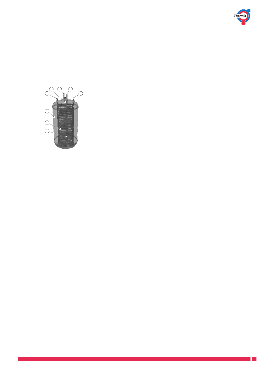
3.5 Water heater
Thermia heat pumps Diplomat and Comfort are supplied with an integrated 180 litre water heater. They are
equipped with a TWS coil, which results in more effective heat transfer and more efficient layering of the water
in the water heater.
1 Tap hot water
Top temperature sensor
2
3 Water heater
4 TWS coil
5 Start temperature sensor
6 Supply line to TWS coil
7 Return line from TWS coil
8 Cold water line
Hot water production is prioritised over heat production.
The temperature of the hot water cannot be adjusted. Hot water production does not stop at a preset water
temperature; it stops when the compressor’s operating pressure switch reaches its maximum pressure. This
corresponds to a hot water temperature of approximately 50–55°C in normal conditions.
To prevent the build up of bacteria in the water tank, the temperature of the water is increased at regular intervals using the integrated electrical heater (anti-legionella function). The factory-set time interval is seven days
(can be adjusted). When the anti-legionella function is active, the heat pump produces hot water until the temperature for the start temperature sensor (5) has reached 60°C.
In the control system’s TEMPERATURE menu, the temperatures that are measured and calculated for the hot
water and heating system supply line are displayed. The current temperature of the top temperature sensor (2)
and the temperature of the supply line during heating and hot water production are displayed. The temperature of the supply line often exceeds the maximum permitted hot water temperature, usually during hot water
production.
The hot water tanks for Atria differ from the other heat pumps as the function for defrosting the outdoor unit is
different.
Thermia Värmepumpar VUGFD202
9
 Loading...