

Therma-Tru Pre-hung Door Systems User Manual [en, es]
Builder, Subcontractor or Supplier:
Please forward these instructions to the homeowner.
The application performance standards for these products may be governed by
the International Residential Code, International Building Code and other state
and jurisdictional requirements. Copies of performance ratings are available
on our website at www.thermatru.com
.
Installation Instructions for
Pre-hung Door Systems
These installation instructions are designed to assist door installers who have
an understanding of carpentry principles, and know how to properly and
safely use power tools. The purpose of these instructions is to illustrate how
to install a Therma-Tru door system using methods and materials that help
eliminate water related leaks. If the directions are closely followed, the door
system will have a long useful life with good resistance to rain related water
intrusion problems.
These methods are “tried and true” They are used widely by builders and
remodelers who are serious about managing and keeping water outside the
home. Rather than eliminate any steps that may be unclear to you, please call
1-800-THERMATRU and ask for clarification. If you remain unclear, please
seek more professional assistance with the installation.
Different parts of the country have different code requirements, which may
not be covered in these instructions. The installer is responsible for insuring
the installation complies with local codes. If you have unique code
requirements that do not appear please contact 1-800-THERMATRU.
Required Tools & Materials: 2 & 6 foot Levels, Hammer, Putty Knives
(firm & flexible), Framing Square, Caulking Gun, Sturdy Ladder, Shims,
Tape Measure, High Quality Elastomeric or Polyurethane Sealant, Screw
Gun/Drill -1/8 inch Drill Bit, Razor Knife, #2 & #3 Philips Bit, Stapler,
Insulating Material, Eye Protection, Water Resistive Barrier, Flashing
Material, #8 x 2-1/2 inch Exterior Grade Screws, & Optional Sill Pan.
Read all instructions before starting.
Therma-Tru Recommended Best Practices
Use Water Resistive Barrier and Flexible Flashing:
We recommend the use of a Water Resistive Barrier
(WRB) applied to the exterior sheathing (OSB or
other) and the use of an adhesive or flexible flashing
product to seal around the opening. The WRB should
be cut in the opening (follow manufacturer’s
guidelines) with the head of the flap taped up, to be
sealed later in Step 11. The flashing should be applied
in an overlapping manner as shown, always working
from the bottom up (follow manufacturer’s
guidelines).
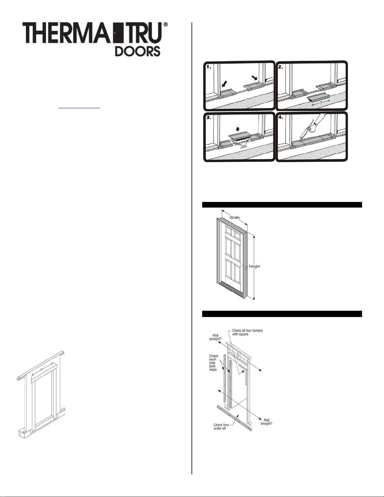
Use a Sill Pan: We recommend you first “dry fit” the sill pan in the opening,
following the instructions furnished with the sill pan. Place the right and left
sill pan ends tight against the sides of the opening. Check the center section
for proper length and if necessary, cut with a hack saw or tin snips. Be sure to
allow 2 inches of overlap at the joints.
Note: Use only the PVC cement provided in the sill pan kit to glue the pieces
together. The sill pan must be sealed to the sub-floor using an Elastomeric or
Polyurethane sealant, but do not apply sealant to the bottom of the sill when
using a sill pan.
Step 1: Check Door Unit.
Check width and height.
Measure size of frame (width and height), not
brickmould.
Remove cleats and packaging, but keep door
fastened closed with transport clip. Do Not
remove the transport clip until instructed to do
so later in Step 7.
Step 2: Check and Prepare Opening.
Note: If additional floor covering clearance is required, attach the shim board
to the sub floor. Be sure to caulk well under the shim board.
Is the opening square? Check all corners with a framing square. Double check
by comparing diagonal measurements. Fix any problems now.
Is the opening the correct size for the
door unit? Check it against the door
frame size now, before installation. The
opening should be frame height plus 1/2
inch, and frame width plus 1/2 inch to
3/4 inch. Fix any problems now.
Are the framing and walls PLUMB? Use
a 6 foot level and check both sides of the
opening, both ways (front to back and
right to left). Fix any problems now.
Is the sub floor level and solid? Provide
a flat, level, clean weight bearing
surface so the sill pan or sill can be
properly caulked and sealed to the
opening. Scrape sand or fill as required.
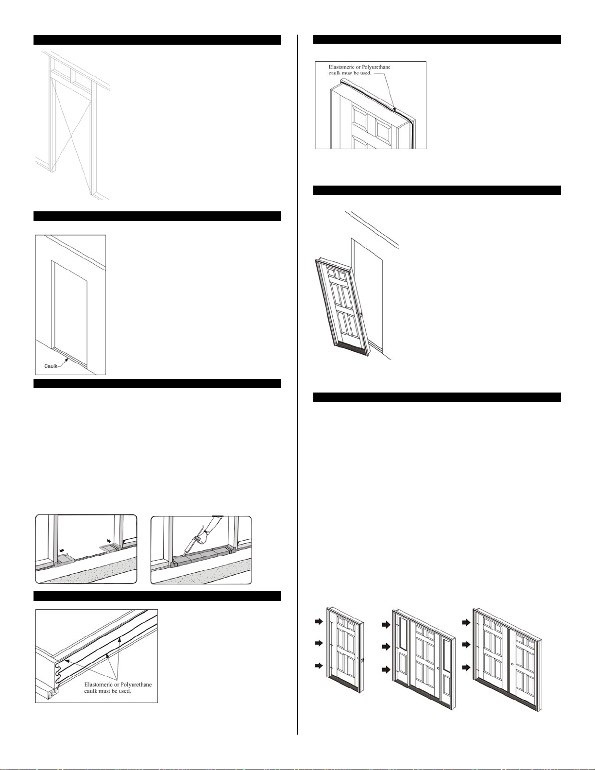
Step 2 cont.: Check and Prepare Opening.
Step 3: Caulk the Sub Floor.
Check to be sure the framing walls around the
opening are in the same plane. Do this by
performing a “string test” for plumb.
String Test for Plumb: Attach a string diagonally
across the opening from the outside, as shown. The
string(s) should gently touch in the center, if not the
opening is “out of plumb” by twice that distance
and needs to be corrected. Flip the string over
itself to check both planes. Fix any problems now.
*An “out of plumb” condition is one of the most
common reasons door units leak air and water.
On the sub floor at opening, place 3 very large beads
of sealant. Run beads full width of the opening.
Use Only Elastomeric or Polyurethane sealant.
Use an Entire Tube when Caulking along the Sub
Floor.
Step 3A: Installation with a Sill Pan.
Place the right and left sill pan ends onto the caulk beads and tightly against
the side of the opening.
Then, liberally coat the overlapped areas and the recessed areas of the pieces
with the PVC cement provided. Place center section(s) in position and hold
pieces together long enough to ensure a good bond.
For added protection, spread a bead of caulk along the glue joints and to
prevent air infiltration, run a bead of caulk along the lower interior edge of the
sill pan. Additional caulking could affect the performance of the sill pan.
Do Not Caulk the bottom of the Sill when using a sill Pan.
Step 3B: Installation without a Sill Pan.
Lay the door unit on edge or face so
that the bottom surface of the sill
can be caulked. Place very large
beads of caulk across the full width
of the sill. Additionally, place beads
of caulk along the junction of the
sill and the jamb and on the bottom
surface of the jambs and
brickmould.
Note: If a sill extender is used, place a large bead of caulk at the junction of
the extender and the sill approach.
Step 3 cont.: Caulking Back side of Brickmould.
Important!
Apply sealant to the back side of
brickmould around the entire perimeter
of the door unit. A 1/2 – 5/8 inch bead
of Elastomeric or Polyurethane caulk is
essential.
Step 4: Place Unit in Opening and Temporarily Fasten.
Lift the unit up. With top edge tilted away from
opening, center the unit and place sill down onto
sill pan or caulk beads and tilt into opening.
For all door unit configurations, note the hinge
locations and mark those locations on the jamb
faces near the door surfaces. Pre-drill 1/8 inch
diameter holes at these locations for screw
placement. A counter sink bit will help to
conceal the screw heads.
Install screws in the center pre-drilled hole
locations on both jambs to temporarily secure
the unit in the place. Do not drive screws
completely in at this time. Use #8 X 2-1/2 inch
or 3 inch exterior grade screws.
Do Not Fasten through the Brickmould.
Step 4 cont.: Plumb Hinge Side Jamb.
Work from side of the door that is weather-stripped.
Use a 6 foot level and plumb the hinge side jamb both ways (right to left and
inside to outside).
Place screws through the hinge side jamb into the studs, at each remaining
hinge location, as shown in the diagrams. Use #8 X 2-1/2 inch or 3 inch
exterior grade screws.
Do Not, drive the screws completely in at this time.
For Single or Double Doors, place screws at each hinge location, so shims can
be placed behind hinges above screws. The screws will keep the shims from
falling down while adjustments are being made.
For Sidelite units, fasten the jamb on the hinge side of the door.
For Double Door and Patio Units, fasten the fixed or passive side of the unit
first.
Single Unit Sidelite Unit Double Unit
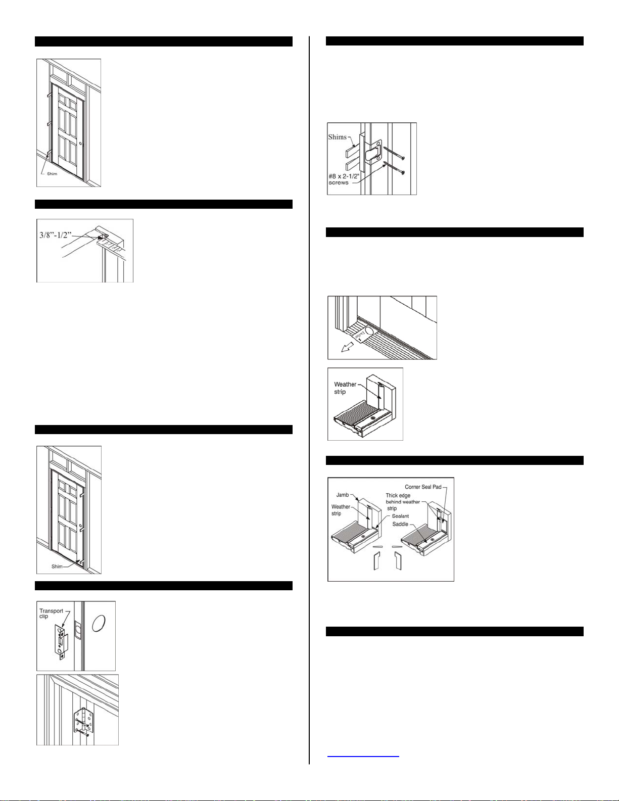
Step 5: Shim at Hinge Locations and Secure Hinge jamb.
Leave door fastened and closed with transport clip.
Shim above screws, behind each hinge location,
between the opening and the jamb.
Use a 6 foot level and re-check hinge jamb to ensure it
is plumb and straight.
Finish driving screws tight in the middle first then top
and bottom last.
Step 6: Adjust Rest of Frame and Fasten.
From the weatherstrip side of the door, check
weatherstrip margins and contact.
Make frame adjustments so the weatherstrip
contacts the door surface equally at the top,
middle and bottom, an even 3/8 inch to 1/2
inch when fully closed.
Secure the lock side jamb with #8 X 2-1/2 or 3 inch screws through the predrilled holes at the top and bottom. Do Not drive screws tight at this time.
From the swing side of the door, shim above the screw locations and make
adjustments so the margins between the door and frame are even top to
bottom.
Note: For Double Doors, make adjustments that effect the alignment, margins
and weatherstrip contact between the doors. Also follow the Astragal Site
Package Instructions for details on properly setting the slide bolt hole
locations.
Step 6 cont: Adjust Rest of Frame and Fasten.
Re-check everywhere for plumb and square, and an
even weatherstrip contact.
Finish driving all screws tight.
Step 7: Remove Transport Clip and Open Door.
Remove the transport clip.
Open and close door to check for smooth
operation.
With the door open, drill 1/8 inch diameter pilot
holes in the top hinge in the 2 screw hole
locations closest to the weatherstrip. Then, install
the #10 X 2-1/2 inch screws (provided) through
the hinge, into the stud, to anchor the door frame
and prevent sagging.
Step 7 cont.: Remove Transport Clip and Ope n Door.
For Sidelite and Patio Units: With the door open, check to determine if the 21/2 inch long hinge screws were pre-installed in the hinges. If not, drill 1/8
inch diameter pilot holes and install the long hinge screws in the hole
locations closest to the weatherstrip.
Close the door and carefully shim between the jamb and the opening behind
the adjustable strike plate area.
Then open the door and drill 1/8 inch dia. pilot
holes and install the #8 X 2-1/2 inch screws
(provided) through the strike plate holes to
secure the lock side jamb and provide security.
weatherstrip contact and door operation, then
finish tightening screws.
Step 8: Adjust Sill.
Your door unit may have an adjustable threshold cap. When properly
adjusted, it should be snug and slightly difficult to pull a dollar bill out from
under the door when it is fully closed. The dollar bill should be able to be
removed without tearing.
Step 9: Install Corner Seal Pads – Inswing units Only.
The bottom of the pad is the same width of the threshold cap to help with
alignment during installation.
Step 10: Additional Frame Anchoring.
If sill is prepared for anchoring screws, place appropriate screws through
the sill into the sub floor where needed. (Primarily on Outswing Sills)
We recommend that you provide additional frame anchoring as shown
here. Certain states or jurisdictions, notably Florida and the coast of
Texas, have specific installation requirements and may require
installation in strict accordance with the product approval for a specific
product. You should always check with the local authority having
jurisdiction for any specific installation requirements that may apply.
Specific product approval installation instructions, including those
required for the High Velocity Zone (HVHZ), are also available at
www.thermatru.com
Adjust strike plate in or out for proper
This check should be performed at each
adjustment screw location.
After adjusting the threshold cap, ensure that the
weatherstrip is flush with the top of the threshold
cap. Trim as necessary.
Apply sealant (Polyurethane or
Elastomeric) at the joint where the
threshold cap meets the door jambs.
Remove the self-stick paper from
the corner seal pads and apply to the
door jamb, with the bottom lined up
evenly with the top of the threshold
cap. When the pad is correctly
installed, the tab is on top and the
narrow part is on the bottom.
 Loading...