


Installation
Pre-Hung Unit Installation ................................ 1.3
Pre-Hung Venting Unit Installation ............... 1.11
Pre-Hung Arch/Radius Unit Installation ........1.19
Multi-Point Lock
Quick Tip Sheet & Instructions ...................... 1.21
Sill Pan Installation Instructions .................... 1.29
Paintable & Stainable Aluminum Astragal
Site Installation Instructions .......................... 1.30
Multi-Point Shootbolt Paintable & Stainable
Astragal Installation Instructions ................... 1.33
Coastal Astragal 2 Installation Instructions .. 1.36
Multi-Point Shootbolt
Coastal Astragal 2 Installation Instructions .. 1.39
French Door System Outswing Astragal
Security Cover Installation ............................. 1.42
Transom Installation Instructions .................. 1.43
Elliptical Transom Casing Instructions .........1.55
Installation
Adjusta-Fit 2 Prehanging Instructions .......... 1.56
Sill Corner Seal Instructions .......................... 1.60
Adjustable Sill Cover Instructions ................. 1.61
Grille Installation Instructions ........................ 1.63
SDL Bar Installation Instructions ................... 1.65
Spring Hinge Instructions ............................... 1.70
Screen installation .......................................... 1.71
SITE 1 2014 1.1

Installation
1.2 2014 SITE 1

Pre-Hung Unit Installation
Builder, Subcontractor or Supplier:
Please forward these instructions to the homeowner.
The application performance standards for these products may be governed by
the International Residential Code, International Building Code and other state
and jurisdictional requirements. Copies of performance ratings are available
on our website at www.thermatru.com
.
Installation Instructions for
Pre-hung Door Systems
These installation instructions are designed to assist door installers who have
an understanding of carpentry principles, and know how to properly and
safely use power tools. The purpose of these instructions is to illustrate how
to install a Therma-Tru door system using methods and materials that help
eliminate water related leaks. If the
directions are closely followed, the door
system will have a long useful life with good resistance to rain related water
intrusion problems.
These methods are “tried and true” They are used widely by builders and
remodelers who are serious about managing and keeping water outside the
home. Rather than eliminate any steps that may be unclear to you, please call
1-800-THERMATRU and ask for clarific
ation. If you remain unclear, please
seek more professional assistance with the installation.
Different parts of the country have different code requirements, which may
not be covered in these instructions. The installer is responsible for insuring
the installation complies with local codes. If you have unique code
requirements that do not appear please contact 1-800-THERMATRU.
Required Tools
& Materials: 2 & 6 foot Levels, Hammer, Putty Knives
(firm & flexible), Framing Square, Caulking Gun, Sturdy Ladder, Shims,
Tape Measure, High Quality Elastomeric or Polyurethane Sealant, Screw
Gun/Drill -1/8 inch Drill Bit, Razor Knife, #2 & #3 Philips Bit, Stapler,
Insulating Material, Eye Protection, Water Resistive Barrier, Flashing
Material, #8 x 2-1/2 inch Exterior Grade Screws, & Optional
Sill Pan.
Read all instructions before starting.
Therma-Tru Recommended Best Practices
Use Water Resistive Barrier and Flexible Flashing:
We recommend the use of a Water Resistive Barrier
(WRB) applied to the exterior sheathing (OSB or
other) and the use of an adhesive or flexible flashing
product to seal around the opening. The WRB should
be cut in the opening (follow manufacturer’s
guidelin
es) with the head of the flap taped up, to be
sealed later in Step 11. The flashing should be applied
in an overlapping manner as shown, always working
from the bottom up (follow manufacturer’s
guidelines).
Use a Sill Pan:
We recommend you first “dry fit” the sill pan in the opening,
following the instructions furnished with the sill pan. Place the right and left
sill pan ends tight against the sides of the opening. Check the center section
for proper length and if necessary, cut with a hack saw or tin snips. Be sure to
allow 2 inches of overlap at the joints.
Note: Use only the PVC cement provided in the sill pan kit to glue the pieces
together. The sill pan must be sealed to the sub-floor using an Elastomeric or
Polyurethane sealant, but do not apply sealant to the bottom of the sill when
using a sill pan.
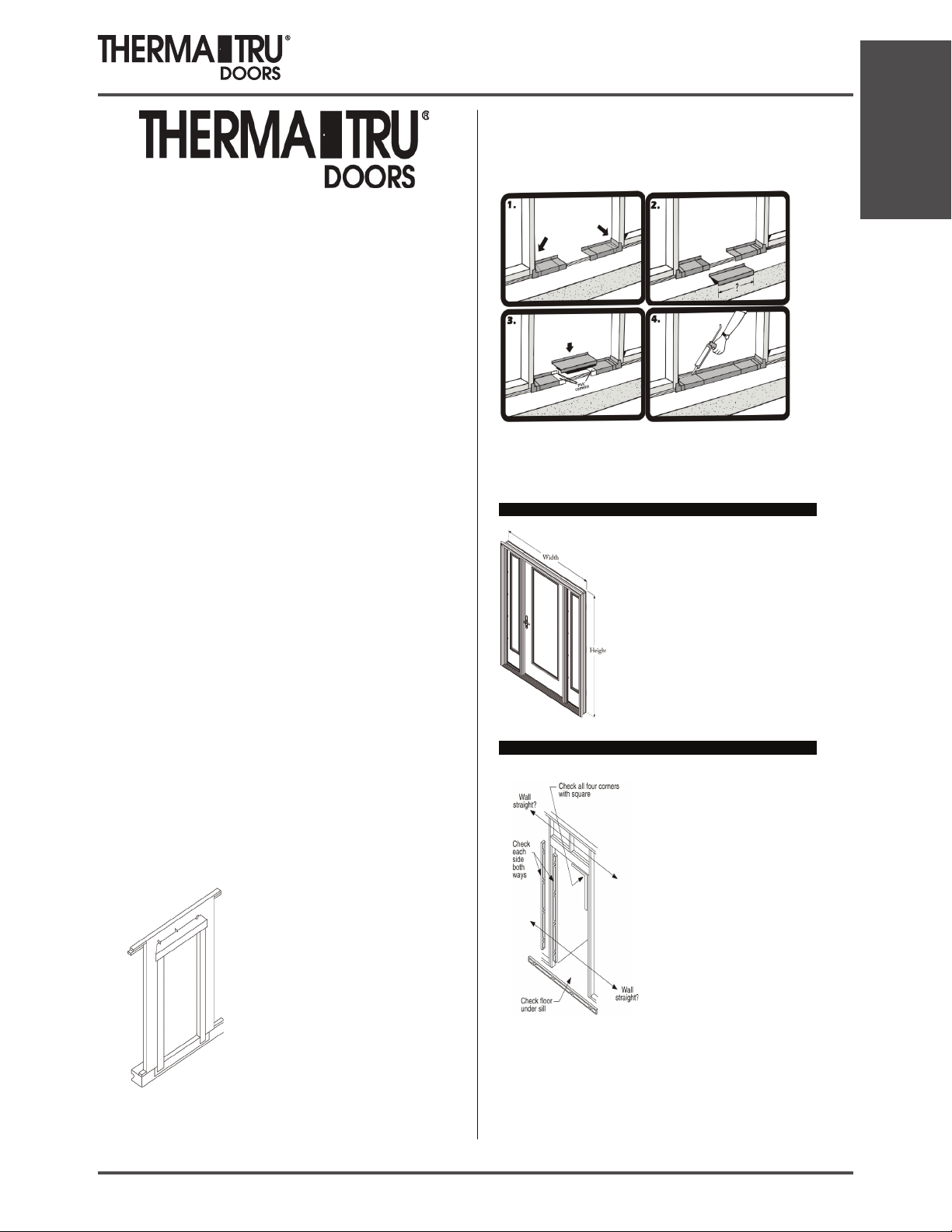
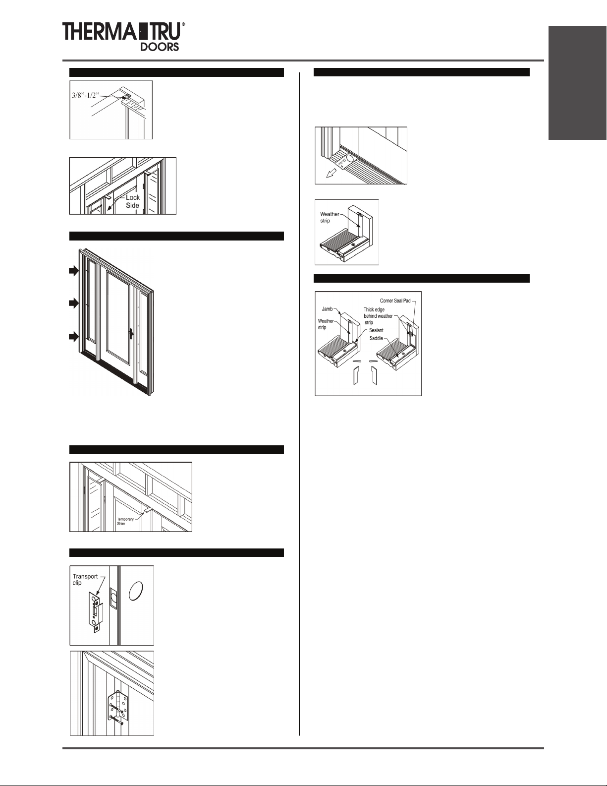
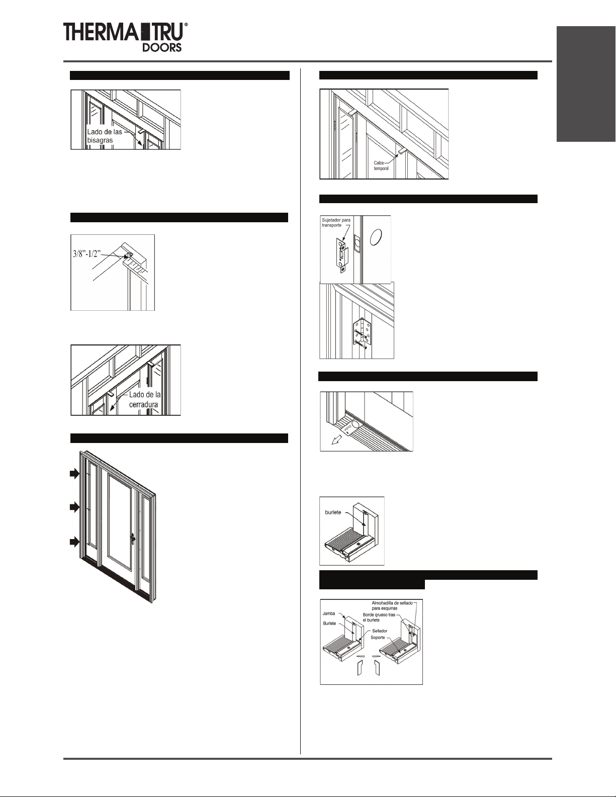
Step 1: Check Door Unit.
Check width and height.
Measure size of frame (width and height), not
brickmould.
Remove cleats and packaging, but keep door
fastened closed with transport clip. Do Not
remove the transport clip until instructed to d
o
so later in Step 7.
Step 2: Check and Prepare Opening.
Is the opening the correct size for th
e
door unit? Check it against the door
frame size now, before installation. The
opening should be frame height plus 1/2
inch, and frame width plus 1/2 inch t
o
3/4 inch. Fix any problems now.
Are the framing and walls PLUMB? Use
a 6 foot level and check both sides of th
e
opening, both ways (front to back and
right to left). Fix any problems now.
Is the sub floor level and solid? Provid
e
a flat, level, clean weight bearing
surface so the sill pan or sill can be
properly caulked and sealed to the
opening. Scrape sand or fill as required.
Note: If additional floor covering clearance is required, attach the shim board
to the sub floor. Be sure to caulk well under the shim board.
Is the opening square? Check all corners with a framing square. Double check
by comparing diagonal measurements. Fix any problems now.
Installation
SITE 1 2014 1.3
Installation
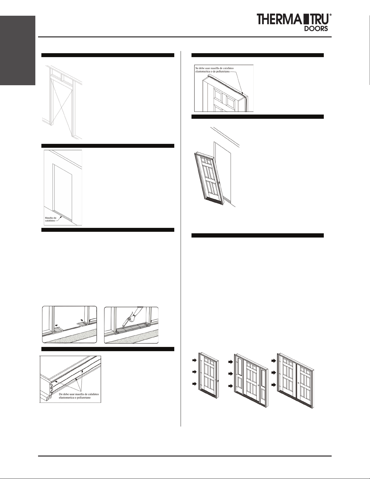
Step 2 cont.: Check and Prepare Opening.
Check to be sure the framing walls around the
opening are in the same plane. Do this by
performing a “string test” for plumb.
String Test for Plumb: Attach a string diagonally
across the opening from the outside, as shown. The
string(s) should gently touch in the center, if not the
opening is “out of plumb” by twice that distance
and needs to be corrected. Flip the string over
itself to check
both planes. Fix any problems now.
*An “out of plumb” condition is one of the most
common reasons door units leak air and water.
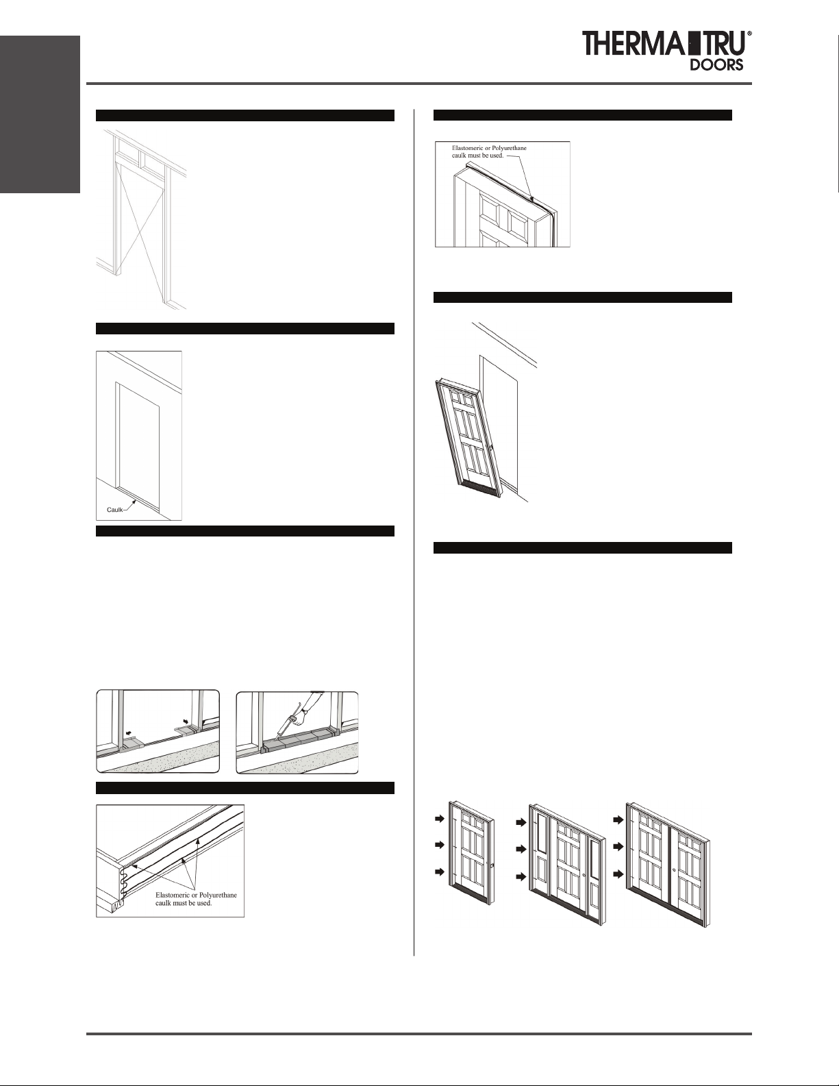
Step 3: Caulk the Sub Floor.
On the sub floor at opening, place 3 very large beads
of sealant. Run beads full width of the opening.
Use Only Elastomeric or Polyurethane sealant.
Use an Entire Tube when Caulking along the Sub
Floor.
Step 3A: Installation with a Sill Pan.
Place the right and left sill pan ends onto the caulk beads and tightly against
the side of the opening.
Then, liberally coat the overlapped areas and the recessed areas of the pieces
with the PVC cement provided. Place center section(s) in position and hold
pieces together long enough to ensure a good bond.
For added protection, spread a bead of caulk al
ong the glue joints and to
prevent air infiltration, run a bead of caulk along the lower interior edge of the
sill pan. Additional caulking could affect the performance of the sill pan.
Do Not Caulk the bottom of the Sill when using a sill Pan.
Step 3B: Installation without a Sill Pan.
Lay the door unit on edge or face so
that the bottom surface of the sill
can be caulked. Place very large
beads of caulk across the full width
of the sill. Additionally, place beads
of caulk along the junction of the
sill and the jamb and on the bottom
surface of the jambs and
brickmould.
Note: If a sill extender is used, place a large bead of caulk at the junction of
the extender and the sill approach.
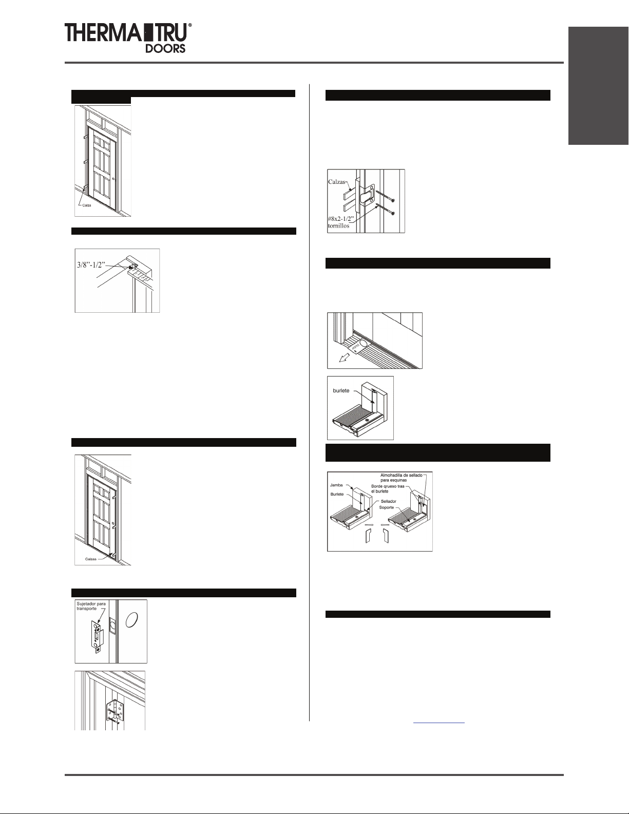
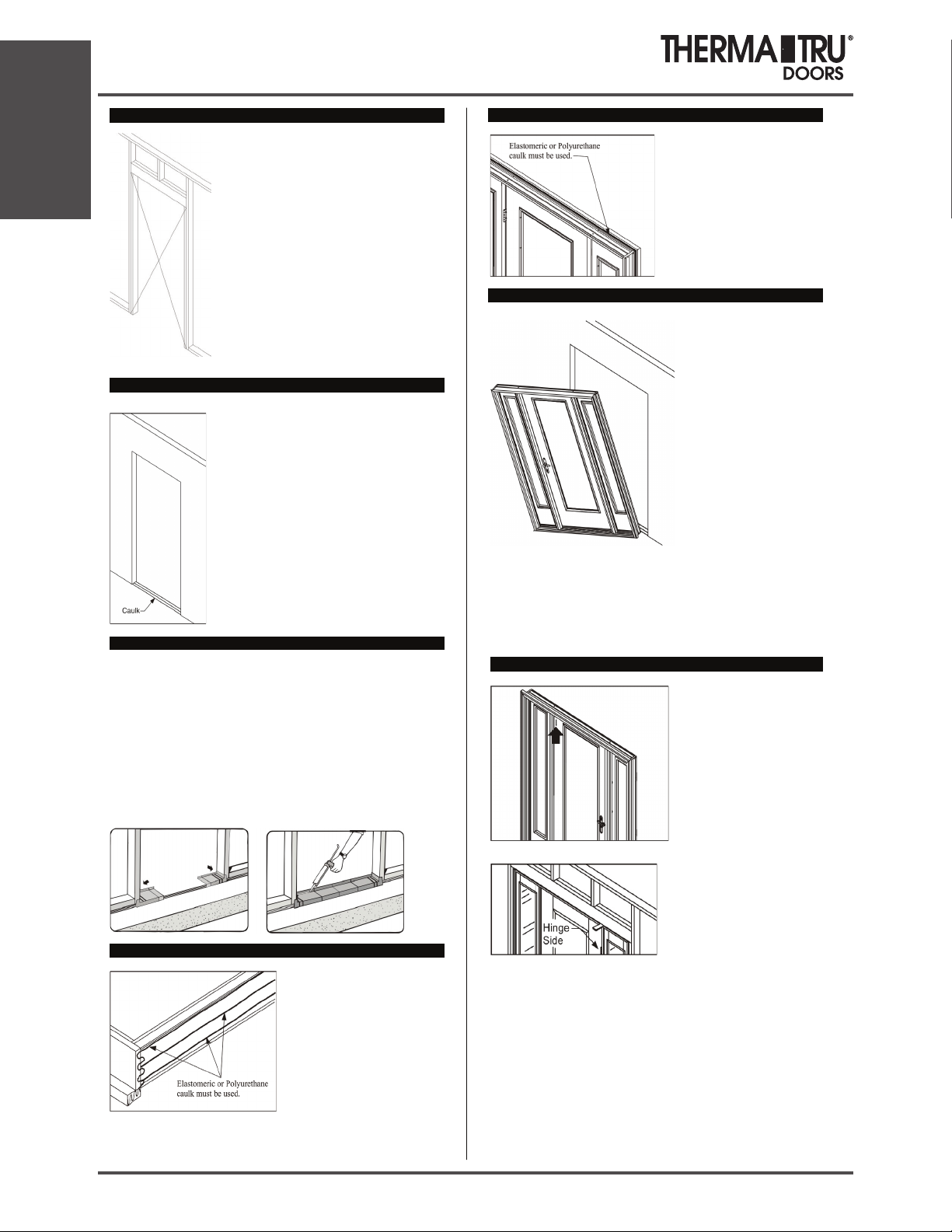
Step 3 cont.: Caulking Back side of Brickmould.
Important!
Apply sealant to the back side of
brickmould around the entire perimeter
of the door unit. A 1/2 – 5/8 inch bead
of Elastomeric or Polyurethane caulk is
essential.
Step 4: Place Unit in Opening and Temporarily Fasten.
Lift the unit up. With top edge tilted away from
opening, center the unit and place sill down onto
sill pan or caulk beads and tilt into opening.
For all door unit configurations, note the hinge
locations and mark those locations on the jamb
faces near the door surfaces. Pre-drill 1/8 inch
diameter holes at these locations for screw
placement. A counter sink bit will help to
conceal the screw heads.
Install screws in the center pre-drilled hole
locations on both jambs to temporarily secure
the unit in the place. Do not drive screws
completely in at this time. Use #8 X 2-1/2 inch
or 3 inch exterior grade screws.
Do Not Fasten through the Brickmould.
Step 4 cont.: Plumb Hinge Side Jamb.
Work from side of the door that is weather-stripped.
Use a 6 foot level and plumb the hinge side jamb both ways (right to left and
inside to outside).
Place screws through the hinge side jamb into the studs, at each remaining
hinge location, as shown in the diagrams. Use #8 X 2-1/2 inch or 3 inch
exterior grade screws.
Do Not drive the screws completely in at this time.
For Single or Double Doors, place screws at each hinge location, so shims can
be placed behind hinges above screws. The screws will keep the shims from
falling down while adjustments are being made.
For Sidelite units, fasten the jamb on the hinge side of the door.
For Double Door and Patio Units, fasten the fixed or passive side of the unit
first.
Single Unit Sidelite Unit Double Unit
Pre-Hung Unit Installation
1.4 2014 SITE 1
Pre-Hung Unit Installation
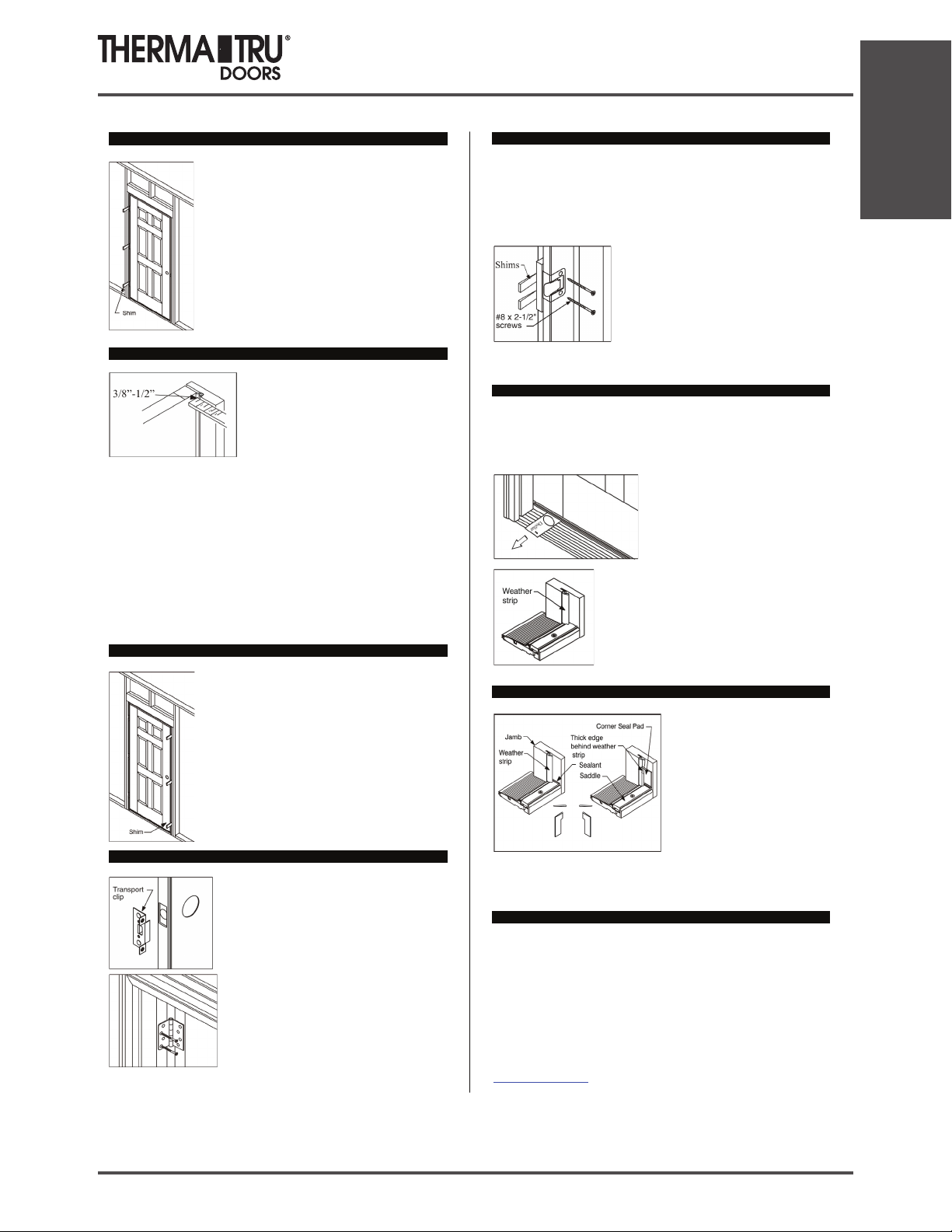
Step 5: Shim at Hinge Locations and Secure Hinge jamb.
Leave door fastened and closed with transport clip.
Shim above screws, behind each hinge location,
between the opening and the jamb.
Use a 6 foot level and re-check hinge jamb to ensure it
is plumb and straight.
Finish driving screws tight in the middle first then top
and bottom last.
Step 6: Adjust Rest of Frame and Fasten.
From the weatherstrip side of the door, check
weatherstrip margins and contact.
Make frame adjustments so the weatherstrip
contacts the door surface equally at the top,
middle and bottom, an even 3/8 inch to 1/2
inch when fully closed.
Secure the lock side jamb with #8 X 2-1/2 or 3 inch screws through the predrilled holes at the top and bottom. Do Not
drive screws tight at this time.
From the swing side of the door, shim above the screw locations and make
adjustments so the margins between the door and frame are even top to
bottom.
Note: For Double Doors, make adjustments that effect the alignment, margins
and weatherstrip contact between the doors. Also follow the Astragal Site
Package Instructions for details on properly setting the slide
bolt hole
locations.
Step 6 cont: Adjust Rest of Frame and Fasten.
Re-check everywhere for plumb and square, and an
even weatherstrip contact.
Finish driving all screws tight.
Step 7: Remove Transport Clip and Open Door.
Remove the transport clip.
Open and close door to check for smooth
operation.
With the door open, drill 1/8 inch diameter pilot
holes in the top hinge in the 2 screw hole
locations closest to the weatherstrip. Then, install
the #10 X 2-1/2 inch screws (provided) through
the hinge, into the stud, to anchor the door frame
and prevent sagging.
Step 7 cont.: Remove Transport Clip and Open Door.
For Sidelite and Patio Units: With the door open, check to determine if the 21/2 inch long hinge screws were pre-installed in the hinges. If not, drill 1/8
inch diameter pilot holes and install the long hinge screws in the hole
locations closest to the weatherstrip.
Close the door and carefully shim between the jamb and the opening behind
the adjustable strike plate area.
Then open the door and drill 1/8 inch dia. pilot
holes and install the #8 X 2-1/2 inch screws
(provided) through the strike plate holes to
secure the lock side jamb and provide security.
Adjust strike plate in or out for proper
weatherstrip contact and door operation, then
finish tightening screws.
Step 8: Adjust Sill.
Your door unit may have an adjustable threshold cap. When properly
adjusted, it should be snug and slightly difficult to pull a dollar bill out from
under the door when it is fully closed. The dollar bill should be able to be
removed without tearing.
This check should be performed at each
adjustment screw location.
After adjusting the threshold cap, ensure that the
weatherstrip is flush with the top of the threshold
cap. Trim as necessary.
Step 9: Install Corner Seal Pads – Inswing units Only.
Apply sealant (Polyurethane or
Elastomeric) at the joint where the
threshold cap meets the door jambs.
Remove the self-stick paper from
the corner seal pads and apply to the
door jamb, with the bottom lined up
evenly with the top of the threshold
cap. When the pad is correctly
installed, the tab is on top and the
narrow part is on the bottom.
The bottom of the pad is the same width of the threshold cap to help with
alignment during installation.
Step 10: Additional Frame Anchoring.
If sill is prepared for anchoring screws, place appropriate screws through
the sill into the sub floor where needed. (Primarily on Outswing Sills)
We recommend that you provide additional frame anchoring as shown
here. Certain states or jurisdictions, notably Florida and the coast of
Texas, have specific installation requirements and may require
installation in strict accordance with the product approval for a specific
product. You should always check with the local authority having
jurisdiction for any specific installation requirements that may apply.
Specific product approval installation instructions, including those
required for the High Velocity Zone (HVHZ), are also available at
www.thermatru.com
Installation
SITE 1 2014 1.5
Installation
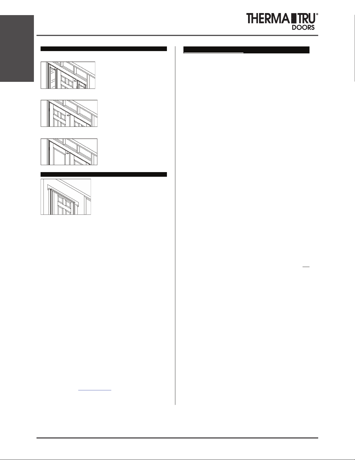
Step 10 cont.: Additional Frame Anchoring.
Doors with Sidelites:
Shim above mull post or jambs
separating doors and sidelites. Screw
through the frame into the header,
adjacent to the shims.
Double doors:
Place temporary shims above the center
of the head frame, where doors meet.
Pre-drill and insert a screw through
frame into header, then remove the
temporary shims.
Patio Doors:
Shim above the mull post(s), Pre-drill
and insert a scre
w through the frame
into the header, at either side of the
post.
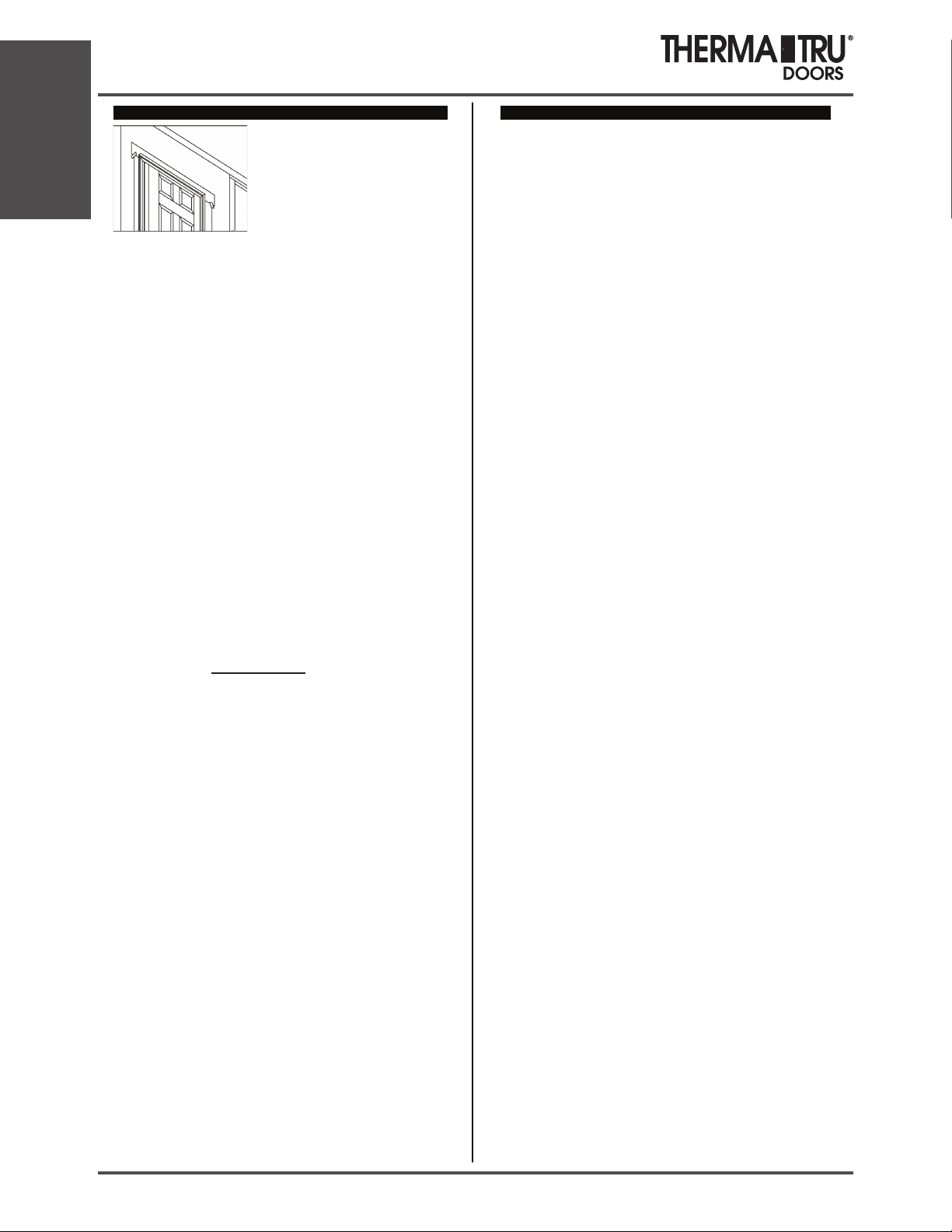
Step 11: Weatherproof, Finish and Maintain.
Provide and maintain a properly installed
cap or head flashing to protect top of
surfaces from Water intrusion and
damage. Tape and properly seal the top
flap of the Water Resistive Barrier (WRB)
over the head flashing.
Caulk around entire “weather” side of unit,
sealing along the brickmould to the flashing material or siding and seal all
joints betwee
n the jambs and moldings.
Seal the joints between the exterior hardware trim and the door face to
prevent air and water infiltration.
Place and set galvanized finish nails through the brickmould around the
perimeter. Use exterior grade screws if you are installing a storm door to the
brickmould. Countersink all fasteners and cover with exterior grade putty.
Add insulation material to the cavi
ty between the opening and the unit to
reduce air infiltration and heat transfer.
All Therma-Tru Steel doors must be finished within several days of the
installation date for continued warranty coverage. For Fiberglass doors the
finishing requirement is within 6 months of installation.
Paint or stain according to Therma Tru Finishing instructions. Do Not paint
or stain the weatherstrip, it is “
friction-fit” and easily removed for painting or
staining.
All 6 sides of the doors must be finished. For out-swing doors the sides, top
and bottom must be inspected and maintained as regularly as all other
surfaces.
All bare wood surfaces such as the door frame exposed to weather should be
primed and painted or stained and top coated within two weeks of exposure
for best performance.
Maintain
or replace sealants and finishes as soon as any deterioration is
evident. For semi-gloss or glossy paint or clear coats, do this when the surface
becomes dull or rough. More severe climates and exposures will require more
frequent maintenance.
Access our website www.thermatru.com
for printable versions of the
installation and Same Day Stain finishing instructions and to view our
Troubleshooting video for minor installation issues and adjustments.
Finishing Instructions.
Work only when temperatures are between 50°and 90°F and with
humidity less than 85%. Do not finish in direct sunlight.
Steel and Smooth-Star® Doors:
To paint Doors: Clean first with mild detergent and water or use a TSP (tri-
sodium phosphate) solution. Rinse well and allow to dry completely. Mask
off hardware, glass and remove weatherstripping before painting. Use highquality acrylic latex house paint, following manufacturer’s directions for
application. Use exterior grade finishes for outside surfaces. Paint edges and
exposed ends of door.
To Paint Doorlite Frames: Remove any excess glass glazing sealant by first
spraying with a window cleaner or water. Use a single edge razor blade to
score the glazing along the edge of the frame. Holding the razor blade at a 45
degree angle, scrape glazing from glass. Wipe remaining residue off with
window cleaner or mineral spirits. Clean frame with a mild detergent and
water, or use a TSP solution. Rinse well and allow to dry completely. Mask
off glass. Prime door lite frames with an alkyd- or acrylic-based primer.
Allow primer to dry before applying finish paint coats. Use high-quality
acrylic latex house paint, following manufacturer’s application instructions.
Use exterior grade finishes for outside surfaces.
Classic-Craft® and Fiber-Classic® Doors:
To Finish Doorlite Frames and Panel Inserts:
Remove any excess glazing sealant by first spraying with a window cleaner or
water. Use a single edge razor blade to score the glazing along the edge of the
frame. Holding the razor blade at a 45° angle, scrape glazing from glass.
Wipe remaining residue off with window cleaner or mineral spirits. Mask off
glass. Paint or stain using same materials as for the door. (See below).
To Paint Doors:
Clean first with mild detergent and water or use a TSP (tri-sodium phosphate)
solution. Rinse well and allow to dry completely. Prime with an alkyd- or
acrylic-based primer. Allow primer to dry completely, then paint with acrylic
latex house paint, following paint manufacturer’s application instructions.
Use a primer and paint that are compatible. Use exterior grade finishes for
outside surfaces. Paint edges and exposed ends of door.
To Stain Doors:
Clean first with a clean cloth and mineral spirits and allow to air dry or wash
door with mild detergent and water, or a TSP (tri-sodium phosphate) solution.
Rinse well and allow to dry completely. For stained surfaces, we only
recommend the use of the stain and clear coat products found in the Therma-
Tru Same-Day Stain™ Finishing Kit. Apply stain with a rag. The longer
the stain is left to “setup” before wiping off, the darker the color will be.
Using a clean rag, wipe off the stain to the color shade you desire. Remove
any excess stain from the panel grooves with the foam brush provided; allow
the stain to dry for at least 6 hours before applying topcoat. See Therma-Tru
Same-Day Stain™ Finishing Kit instructions for complete details.
Warning:
Modification or machining of this product can release wood dust, a
substance known to the State of California to cause cancer.
Pre-Hung Unit Installation
1.6 2014 SITE 1
Pre-Hung Unit Installation
Constructor, subcontratista o proveedor:
Entregue estas instrucciones al propietario.
Los estándares de rendimiento de aplicación para estos productos están regidos por el
Código Residencial Internacional, el Código de C onstrucción Internacional y por otras
normas estatales o jurisdiccionales. Las copias de las c lasificaciones de rendimiento se
encuentran disponibles en nuestro sitio Web en ww
w.thermatru.com.
Instrucciones de instalación para
sistemas de puertas preafabricadas
Estas instrucciones de instalación están diseñadas para a yudar a los instaladores de
puertas que t ienen nociones principios de carpintería y saben cómo usar herramientas
eléctricas de manera adecuada y segura. El propós ito de estas instrucciones es demostrar
la manera de instalar un sistema de puertas Therma-Tru mediante el u
so de métodos y
materiales que ayudan a eliminar las filtraciones relacionadas con el agua. Si se siguen
cuidadosamente las instrucciones, el sistema de puertas tendrá una vida útil prolongada
con una buena resistencia a los problemas relacionados con el agua de lluvia.
Estos métodos estan “comprobados”. So n usados frecuentemente por los constructores y
remodeladores preocupados por mantener el
agua fuera de las casa. En caso de que estas
instrucciones no aclaren sus dudas, no se salten ninguno de los, y llame al 1-800-
THERMATRU y pida aclaraciones. S i todavía tiene dudas, busque más ayuda
profesional para la instalación.
Las diferentes regiones del país cuentan con difere ntes requisitos de códigos, que pueden
no estar cubiertos por estas instrucciones. El instalador es el responsable d
e asegurar que
la instalación cumpla con los códigos lo cales. Si se aplican códigos únicos que no
aparecen, póngase en contacto con el 1-800-THERMATRU.
Herramientas y materiales necesarios: niveles de 2’ y 6’, martillo, espátulas
(rígidas y flexibles), escuadra de e nmarcar, pistola para calafateo, escalera resistente,
calzas, cinta métrica, sellador elastomérico o de poliuretano de alta calidad,
pistola
atornilladora o taladro: taladro con broca para taladro de 1/8”, navaja, puntas Philips #2 y
#3, engrapadora, material de aislamiento, gafas de protección, barrera resistente a l agua,
material tapajuntas, tornillos para exteriores #8 x 2-1/2” y revestimiento para alféi zar
opcional.
Lea todas las instrucciones antes de comenzar.
Mejores prácticas recomendadas por Therma-Tr u
Use barreras re
sistentes al aqua y tapajuntas flexibles:
Recomendamos el uso de barreras res istentes al a gua (WRB,
por sus siglas en inglés) ap licadas al revestimiento exterior
(OSB u otras) y el uso de productos adhesivos o de tapajuntas
flexibles para sellar el perímetro de la abertura. Se debe cortar
la WRB en la abertura (siga las pa utas de l fabricante) co n e l
cabezal de la lengüeta cubierta con cinta adhesi
va, para
sellarla después en el paso 11. Se debe aplicar el tapajuntas de
manera superpuesta, como se muestra, siempre co menzando
desde la parte inferior hacia arriba (siga las pautas del
fabricante).
1994-2009 Therma Tru Corp. All rights reserved.
Therma-Tru Doors is an operating company of Fortune Brands, Inc.
Issued 4/11 Rev.G Part# MSDRIST65
Use un revestimiento para alféizar: recomendamos que primero compruebe que el
revestimiento para alféizar cabe en la abertura siguiendo las instrucciones incluidas con
éste. Coloque los extremos derecho e izquierdo del revestimiento para alféizar contra los
costados de la abertura. Compruebe que la sección central tenga el largo adecuado y, de
ser necesario, córtela con una sierra de mano o tijeras para hojalata. Asegúrese de dejar
5,08 centímetros de superposición para las uniones.
Nota: Use sólo el cemento PVC incluido en el kit de revestimiento para alféizar para unir
las piezas. El alféizar se debe sellar al subsuelo con un sellador elastomérico o de
poliuretano, pero no aplique se llador a la parte inferior del alféizar usando un
revestimiento para alféizar
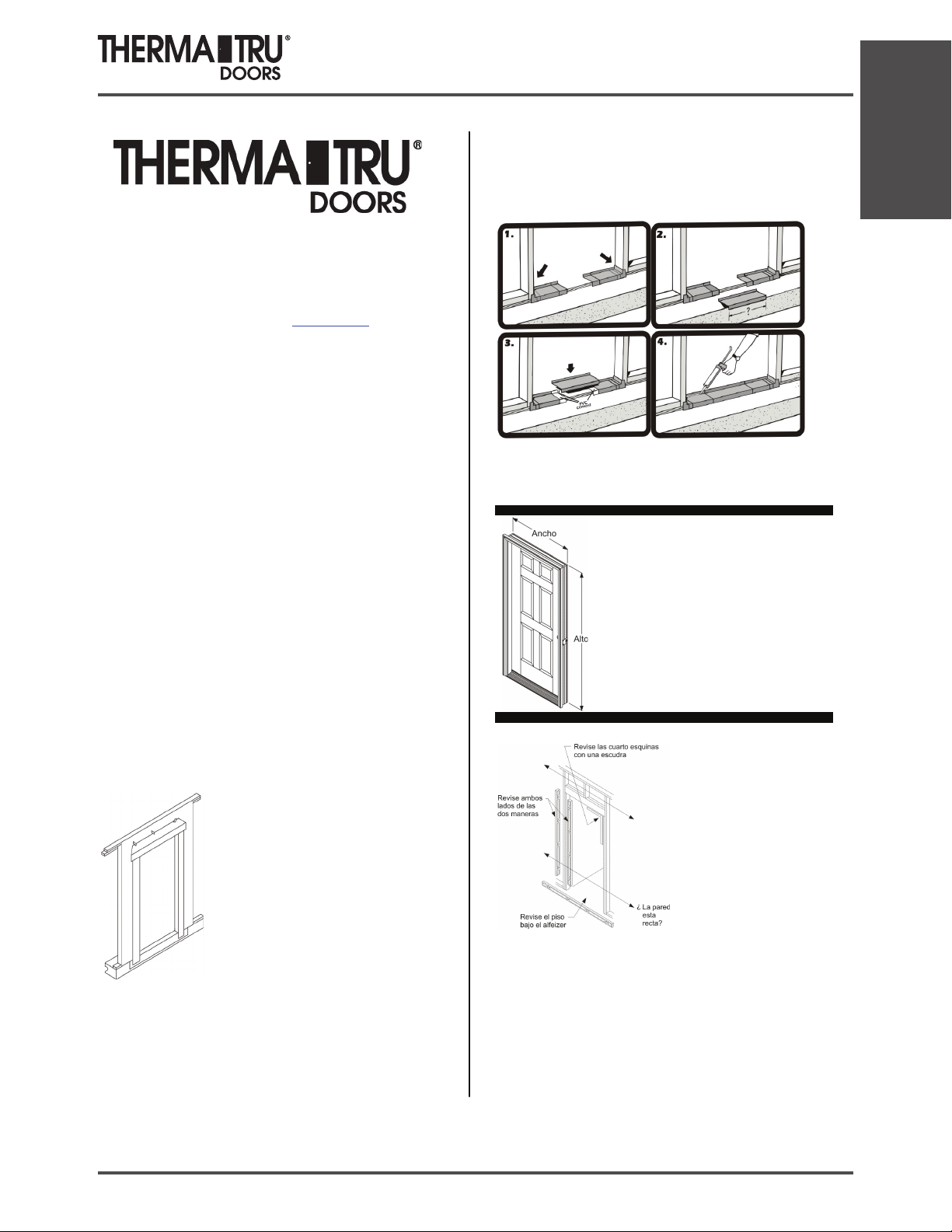
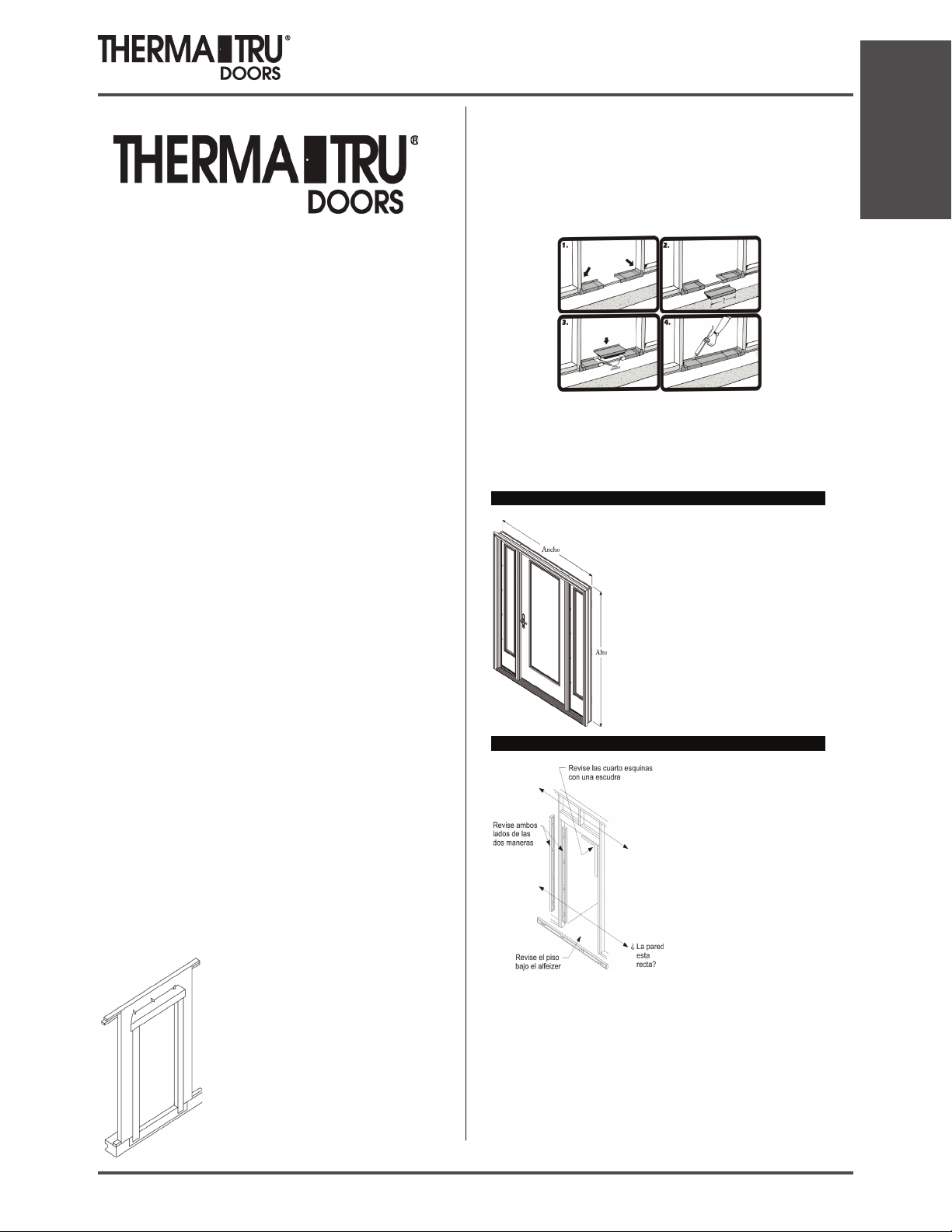
Paso 1: revise la puerta.
Revise el ancho y alto.
Mida el tamaño del marco (ancho y alto), no de la moldura.
Retire las tablitas y e l empaque, pero mantenga la puerta
fijamente cerrada con e l sujetador para transporte. No retire el
sujetador para transporte hasta que se le indique hacerlo más
adelante en el paso 7.
Paso 2: revise y prepare la abertura.
¿La abertura es del tamaňo correcto para
la puerta? Compárela con el tamaňo del
marco de la puerta ahora, antes de la
instalación. La abertura debe tener el
alto del marco más 1.27 cm y el ancho
del macro más 1,27 a 1,91 c m. Resuelva
cualquier problema en este momento.
¿Los marcos y las paredes están A
PLOMO? Use un nivel de 6 pies y
revise ambos lados de la abertura, de las
dos maneras (del frente hacia atrás y de
derecha a izquierda). Resuelva
cualquier problema en este momento.
¿El subsuelo está nivelado y sólido? Proporcione u na superficie plana, nivelada y
limpia que soporte el peso, de m anera que se pueda aplicar masilla de calafateo y sellar
de forma adecuada el revestimiento para alféizar o el alféizar a la abertura. Raspe, lije
o rellene según se necesite.
Nota: si se necesita una separación adicional de la cobertura del piso, fije la tabla de
calza al subsuelo. Asegúrese de calafatear bien bajo la tabla de calza.
¿La aber tura está a escuadra? Revise todas las esquinas con una escuadra de enmarcar.
Revise dos veces comparando las medidas diagonales. R esuelva cualquier problema en
este momento.
Installation
SITE 1 2014 1.7
Installation
Paso 2, cont.: revise y prepare la abertura.
Aseqúrese de que las paredes que enmarcan el perímetro
de la abertura están en el mismo plano. Hágalo realizando
una prueba con un cordel para verificar que está a plomo.
Prueba con cordel para verificar que está a plo mo: Coloque
un cordel que cruce diagonalmente la abertura desde el
exterior, como se muestra. Los cordeles se deben tocar
suavemente en
el centro, de lo contrario, la abertura está
“fuera de plomo” por el doble de dicha distancia y se debe
corregir. Voltee el cordel sobre sí mismo para verificar
ambos planos. Resuelva cualquier problema en este
momento.
*
El estado “fuera de plomo” es una de las razones más
comunes por las que las puertas sufren fugas de aire y agua
Paso 3: Aplique masilla de calafateo en el subsuelo.
Coloque 3 cordones de sellador muy grandes en el
subsuelo de la abertura. E xtienda los cordones hasta
alcanzar el ancho total de la abertura.
Use sólo sellador elastomérico o de poliuretano.
Use un tubo completo para calafatear a lo largo del
subsuelo.
Paso 3A: instalación con un revestimiento para alféizar.
Coloque los extremos derecho e izquierdo del revestimiento para alféizar en los cordones
de masilla de calafateo y firmemente contra el costado de la abertura.
Luego, cubra generosamente las áreas superpuestas de las piezas con el cemento PVC
incluido. Coloque las secciones centrales en posición y mantenga juntas las pieza s el
tiempo sufic
iente para asegurar la formación de una buena adhesión.
Para obtener protección adicio nal, esparza un cordón de masilla de calafateo a lo largo de
las uniones de adhesivo y, para evitar la fil tración de aire, extienda un cordón de masilla
de calafateo a lo largo del borde interior inferior de l revestimiento para alféizar. Colocar
masilla de calafateo adicional puede afectar el rendimiento del rev
estimiento para
alféizar.
No calafatee l a parte inferior del alféizar cuando use un revestimiento para alféizar
Paso 3B: instalación sin un revestimiento para alféizar.
Coloque la puerta sobre su borde o frente, de
manera que se pueda calafatear la superficie
inferior del alféizar. Coloque co rdones de
masilla de ca lafateo muy grandes a lo largo
de todo el ancho de l alféizar. Además,
coloque cordones de masilla de calafateo a lo
largo de la unión del alféizar y la jamba y en
la s uperficie inferior de las ja
mbas y las
molduras.
Nota: si usa una extensión para alféizar, coloque un cordón de masilla de calafateo
grande en la unión de la extensión y la entrada de l alféizar.
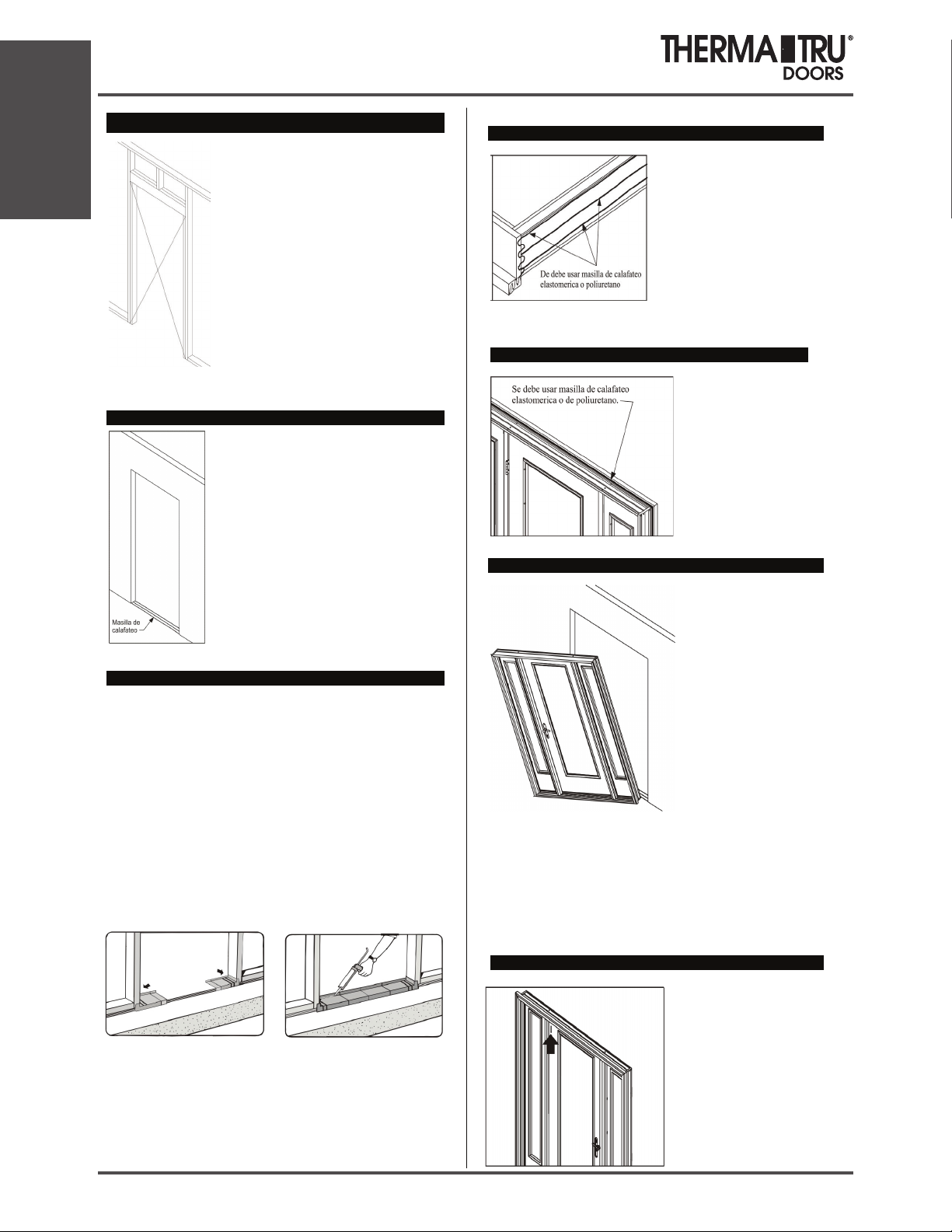
Paso 3, cont.: calafateo de la parte posterior de la moldura.
¡Importante!
Aplique sellador a la parte posterior de la
moldura, en todo el perímetro de la puerta.
Es fundamental colocar un cordón de
masilla de calafateo elastomérica o de
poliuretano de 1,27 a 1,59 cm.
Paso 4: coloque la unidad en la abertura y fije temporalmente.
Levante la unidad. Incline e l borde superior
alejándolo de la abertura y centre la unidad; coloque
el alféizar en el revestimiento para alféizar o los
cordones de masilla de calafateo e inclínelo hacia la
abertura.
Tenga presente la ubicación de las bisagras para todas
las configuraciones de las puertas y márquelas en el
frente de las jambas, cerca de las superficies de la
puerta. Pretaladre orificios de 0,32 cm de diámetro en
estas ubicaciones para colocar los tornillos. Puede
ocultar las cabezas de los tornillos s i usa una broca
para avellanar.
Instale los tornillos en la ubicación del orificio
pretaladrado central de ambas jambas para asegurar la
unidad temporalmente en el lugar. No coloque los tornillos completa mente en este
momento. Use tornillos para exteriores de #8 X 2 -1/2 ó 3 pulgadas.
No los apriete a través de la moldura.
Paso 4, cont.: coloque a plomo el lado de las bisagras de la jamba.
Comience a trabajar desde el lado con burletes de la puerta.
Use un nivel de 6 pies y coloque a plo mo el lado de las bisagras de las ja mbas de las dos
maneras (de derecha a izquierda y del interior al exterior).
Haga pasar los t ornillos a través del lado d e las bisagras de la jamba hasta los montantes,
en cada una de las ubicaciones de las bisagras restantes como se muestra en los
diagramas. Use tornillos para exteriores de #8 X 2-1/2 ó 3 pulgadas.
No coloque los tornillos completamente en este momento.
En el caso de las puertas simples y d obles, coloque los tornillos e n cada una de las
ubicaciones de las bisagras, de manera que se pueda colocar las calzas tras las bisagras y
sobre los tornillos. Los tornillos evitarán que las calzas se caigan mientras se realizan
ajustes.
En el ca so de las unidades con vidrieras laterales, apriete la ja mba en el lado de las
bisagras de la puerta.
En el caso de las unidades de puerta doble y para patio, apriete primero el lado fijo o
pasivo de la unidad.
Unidad simple Unidad con vidriera lateral Unidad doble
Pre-Hung Unit Installation
1.8 2014 SITE 1
Pre-Hung Unit Installation
Paso 5: coloque calzas en las ubicaciones de las bisagras y asegure la
jamba con bisagras.
Deje la puerta fija y cerrada con el sujetador para transporte.
Coloque calzas sobre los tornillos, detrás de cada ubicación de
las bisagras, entre la abertura y la jamba.
Use un nivel de 6 pies y vuelva a verificar la jamba con
bisagras para asegurarse de que está a plomo y recta.
Termine de apretar primero los tornillos del medio, luego los
de la parte superior y finalmen
te los de la parte inferior.
Paso 6: ajuste el resto del marco y apriete.
Verifique los márgenes y contactos de los burletes
desde el lado de la puerta que los tiene.
Ajuste el marco de mane ra que los burletes hagan
contacto con la s uperficie de la puerta de la misma
manera en la parte superior, la parte del medio y la
parte inferior, una distancia pareja de 0,95 a 1,27
centímetros cuando está completamente cerrada.
Asegure la jamba del lado del seguro con tornillos de #8 X 2-1/2 ó 3 pulgadas a través de
los orificios pretaladrados en la parte superior e inferior. No apriete los tornillos en este
momento.
Coloque calzas sobre las ubicaciones de tornillos desde el lado de apertura de la puerta y
realice ajustes de manera que los márgenes entre la puerta y el marco queden parejos
desde la parte superior a la inferio
r.
Nota: en e l caso de las puertas dobles, realice aj ustes que tengan efecto sobre la
alineación, los márgenes y el contacto de los burletes entre las puertas. Además, siga las
instrucciones del paquete del sitio de Astragal para obtener detalles sobre la
configuración adecuada de la ubicación de los orificios para el cerrojo.
Paso 6, cont.: ajuste el resto del marco y apriete.
Vuelva a verificar que todos los lugares estén a plomo y a
escuadra y que los burletes estén en contacto de manera pareja
Termine de apretar todos los tornillos.
Paso 7: retire el sujetador para transporte y abra la puerta.
Retire el sujetador para transporte.
Abra y cierre la puerta para verificar que funciona
correctamente
Con la puerta abierta, taladre orificios guía de 0,32 cm
de diámetro e n la bisagra superior, en las 2 ubicaciones
de los orificios para tornillos más cercanas al burlete.
Luego, instale los tornillos de #10 X 2-1/2 pulgadas
(incluido
s) a través de la bisagra, pasando por el
montante, para anclar el marco de la puerta y evitar que
quede suelta.
Paso 7, cont.: retire el sujetador para transporte y abra la puerta.
Para unidades con vidriera lateral y para patio: con la puerta abierta, verifique y
determine s i se instalaron pre viamente los tornillos para bisagra largos de 2-1/2” en las
bisagras. De no ser así, taladre orificios guía de 0,32 cm de diámetro e instale los tornillos
largos para bisagra en las ubicaciones de orificio más cercanas al burlete.
Cierre la puerta y coloque calzas cuidadosamente e ntre la jamba y la abertura tras el área
de la cerradura de seguridad ajustable.
Luego, abra la puerta y taladre orificios guía de 0,32
cm de diámetro e instale los tornillos de #8 X 2-1/2
pulgadas (incluidos) a través de los orificios de la
cerradura para asegurar la jamba del lado del seguro y
proporcionar seguridad
Ajuste la cerradura hacia adentro o afuera para que
entre en contacto co n el burlete y la puerta funcione de
manera adecuada, luego, termine de apretar los tornillos.
Paso 8: ajuste el alféizar.
Es pos ible q ue s u pue rta te nga una c ubierta para umbral a justable. Cuando se ajusta de
manera adec uada, la puerta debe quedar apretada y de be ser ligera mente d ifícil jalar un
billete de un dólar por debajo de ella c uando está bien cerrada. Se debe poder retirar el
billete de un dólar sin rasgarlo.
Esta verificación se debe rea lizar en cada
ubicación de tornillo de ajuste.
Después de ajustar la cubierta para umbral, asegúrese de
que el burlete está al ras co n la parte superior de la cubierta
para umbral. Recorte si es necesario.
Paso 9: instale las almohadillas de sellado para esquinas: sólo para
unidades de apertura hacia adentro.
Aplique se llador (e lastomérico o de
poliuretano) en la unión entre la cubierta
para umbral y las jambas de la puerta.
Retire e l papel autoadhesivo de las
almohadillas de sellado para esquinas y
aplíquelas a la jamba de la puerta, alinea ndo
de forma pareja la parte inferior con la
parte superior de la cubierta para umbral.
Cuando la almohadilla se instala correctamente, la lengüeta se encontrará encima y la
parte estrecha abajo.
La parte inferior de la almohadilla tiene el mismo ancho que la cubierta para umbral, para
ayudar a alinearlas durante la instalación.
Paso 10: anclaje adicional del marco.
Si el alféizar cuenta con preparación para tornillos de anclaje, coloque los tornillos
adecuados a través de l alféizar y hasta el subsuelo de ser necesario. (Principalmente en
alféizares para apertura hacia afuera).
Le recomendamos proporcionar anclaje adicional a l marco, como lo mostramos aquí.
Algunos estados o jurisdicciones, como es el caso de Florida y la costa de Texas, cuentan
con normativa de instalación específica y pueden req uerir que la instalación se haga de
estricto acuerdo con la aprobación del producto pa ra un producto específico. Usted debe
siempre ver
ificar con la autoridad local que tenga jurisdicción s i existe normativa de
instalación específica que pueda aplicarse. Disponemos de instrucciones específicas de
instalación para aprobación de productos, lo que incluye aquellos requeridos para la zona
de huracanes de alta velocidad, en www.ther matru.com
Installation
SITE 1 2014 1.9

Installation
Paso 10, cont.: anclaje adicional del marco.
Puertas con vidrieras laterales:
Coloque calzas sobre los listones verticales o
las jambas de puerta que separan las puertas
de las vidrieras laterales. Atornille a través del
marco hasta el dintel, junto a las calzas.
Puertas dobles:
Coloque calzas temporales sobre e l centro del
marco del dintel, donde se unen las puertas.
Pretaladre e inserte un tor
nillo, a través del
marco, en el dintel y luego retire las calzas
temporales.
Puertas para patio:
Coloque calzas sobre los listones verticales,
pretaladre e inserte un tornillo, a través del
marco, en el d intel, a cada lado de los
listones.
Paso 11: deje a prueba de intemperie, aplique un acabado y dé mantenimiento.
Proporcione y mantenga una cubierta o un
tapajuntas del d intel adecuadamente instalados
para proteger la parte superior de las superficies
del ingreso de agua y del daño. Coloque cinta
adhesiva y selle de manera adecuada la parte
superior de la lengüeta de la barrera resistente al
agua (WRB) sobre el tapajuntas del dinte
l.
Calafatee alrededor de todo el lado expuesto al c lima de la unidad, sellando a lo largo de
la moldura hasta el material de tapajuntas o los revestimientos y selle todas las uniones
entre las jambas y las molduras.
Selle las uniones e ntre el reborde de los accesorios exteriores y el frente de la puerta para
evitar la filtración de aire y agua.
Coloque y a juste clavos galvanizados para acabado a través de la moldura, alrededo r del
perímetro. Use tornillos para exteriores si está instalando una contrapuerta en la moldura.
Avellane todos los sujetadores y cúbralos con mas illa para exteriores.
Añada material de aislamiento a la cavidad entre la abertura y la unidad, a fin de red ucir
la filtración de aire y la transferencia de calor.
Todas las puertas de acero T herma Tru deben finalizarse dentro de los días siguientes a la
fecha de la instalación para una adecuada cobertura de la garantía. Para puertas de fibra
de vidrio, el acabado debe darse dentro de los 6 meses después de la instalación.
Pinte o tiña de acuerdo con las instrucciones de acabado de Therma Tru. No pinte ni tiña
el burlete, está ajustado para la fricción y se retira fácilmente para pintar o teñir.
Las puertas de apertura hacia fuera deben tener acabados en todos los bordes, los
costados, la parte superior y la parte inferior. Inspeccione y dé mantenimiento a estos
bordes con la misma regularidad que con todas las demás superficies.
Se debe dar acabado a los 6 lados de las puertas. Para las puertas que se abren para
afuera, los lados, la parte superior y la parte inferior deben inspeccionarse y conserva
rse
con la misma regularidad que las otras superficies.
Dé mantenimiento o reemplace los selladores y acabados tan pronto el deterioro sea
evidente. En el caso de la pintura brillante o semibrillante y de las capas transparentes,
hágalo cuando la superficie se vuelva opaca o áspera. Los climas y las exposiciones más
rigurosos necesitarán de mantenimiento más frecuente.
Ingrese a nuestro s itio Web www.thermatru.com para obtener versiones imprimibles
de la instalación e instrucciones para el acabado el mismo día y para consultar nuestro
vídeo de solución de problemas sobre problemas y ajustes menores de la instalación.
Instrucciones para el acabado:
Trabaje sólo cuando las temperaturas s e encuentren entre 10 y 32,2º C y la humedad sea
menor a un 85%. No aplique acabados bajo la luz s olar directa.
Puertas de acero y Smooth-Star®
Para pintar p uertas: primero limpie con un detergente s uave y agua o use una solución
de TSP ( fosfato trisódico). Enjuague b ien y deje secar completamente. Proteja los
accesorios, los vidrios y los burletes antes de pintar. Use pintura látex de casas de alta
calidad y siga las instrucciones del fabricante para su aplicación. Use acabados para
exteriores para las superficies exteriores. Pinte los b ordes y los extremos expuestos de la
puerta.
.
Para pintar marcos de vidrieras para puertas: Primero retire cualquier exceso de
sellador de esmalte para vidrios rociando con un limpiador de ventanas o agua. Use una
navaja de un solo filo para hacer cortes en e l esmalte a lo largo del borde del marco.
Raspe el esmalte del vidr io sosteniendo la cuchilla de la navaja e n un ángulo de 45
grados. Retire el residuo restante con un limpiador de ventanas o aguarrás mineral.
Limpie e l marco con un dete rgente suave y agua o use una solución de TSP. Enjuague
bien y deje secar completamente. Proteja el vidrio. Aplique una pintura base de resina
alquídica o acrílica a los marcos de vidrieras. Deje secar la pintura base antes de aplicar
las capas de pintura de acabado. Use pintura látex de casas de alta calidad y siga las
instrucciones del fabricante para s u aplicación. Use acabados para exteriores para las
superficies exteriores.
Puertas Classic-Craft® y Fiber-Classic®:
Para dar acabado a marcos de vidrieras para puertas y a accesorios para paneles:
primero retire cualquier exceso de se llador de esmalte rociando c on un limpiador de
ventanas o agua. Use una navaja de un solo filo para hacer cortes en el es malte a lo largo
del borde del marco. Raspe el esmalte del vidrio sosteniendo la cuchilla de la navaja en
un ángulo de 45°. Retire el residuo restante con un limpiador de ventanas o aguarrás
mineral. Proteja el vidrio. Pinte o tiña usando los mismos materiales de la puerta.
(Consulte abajo.)
Para pintar puertas:
primero limpie con un detergente suave y agua o use una solución de TSP (fosfato
trisódico). Enjuague bien y deje secar completa mente. Aplique una p intura base de resina
alquídica o acrílica. Deje que la pintura base se seque completamente, luego, pinte con
pintura láte x de casas siguiendo las instrucciones del fabricante para su aplicación. Use
una pintura base y una pintura que s ean compatibles. Use acabados para exteriores para
las superficies exteriores. Pinte los bordes y los extre mos expuestos de la puerta.
Para teñir puertas:
primero limpie con un paño limpio y aguarrás mineral y deje secar a l aire o lave la pu erta
con un detergente suave y agua o una solución de TSP (fosfato trisódico). Enjuague bien
y deje s ecar completamente. En e l caso de las superficies teñidas, sólo recomendamos el
uso de tintes y productos de capas transparentes que se encuentran en el kit para
acabado Therma -Tru Sa me-Day Stain™. Aplique el tinte co n un paño. Mientras más
tiempo se deje el tinte para “asentarse” antes de limpiarlo, más oscuro será el color. Use
un paño limpio para limpiar el tinte hasta lograr el tono del color q ue desea. Retire
cualquier exceso de t inte de las gr ietas del panel con la brocha de espuma que se incluye.
Deje secar e l tinte durante al menos 6 horas antes de aplicar una capa s uperior. Consulte
las instrucciones del kit para acabado Therma-Tru Same-Day Sta in™ para obtener
información detallada.
Advertencia:
La modificación o el mecanizado de este prod ucto puede liberar polvo de madera,
una sustancia que el Estado de California reconoce co mo causante de cáncer
.
Pre-Hung Unit Installation
1.10 2014 SITE 1
Builder, Subcontractor or Supplier:
Please forward these instructions to the homeowner.
Therma-Tru® certified door systems and Therma-Tru® door systems that
require product approval (typically for coastal applications) may require
special assembly, components and installation. Always refer to the certified
system requirements and product approval assembly and installation drawings
on our websit
e for these applications.
Building codes can vary by Jurisdiction, County and/or State. Always check
for any specific assembly or installation that may be required by Code in your
area.
Installation Instructions for Vented Sidelite Door
Systems
These installation instructions are designed to assist door installers who have
an understanding of carpentry principles, and know how to properly and
safely use power tools. The purpose of these instructions is to illustrate how to
install a Therma-Tru® door system using methods and materials that help
eliminate air infiltration and water related leaks. If the directions are closely
followed, the door system will have a long useful life with good resistance to
air and water intrusion problems.
These methods are “tried and true” They are used w
idely by builders and
remodelers who are serious about managing and keeping water outside the
home. Rather than eliminate any steps that may be unclear to you, please call
1-800-THERMATRU and ask for clarification. If you remain unclear, please
seek more professional assistance with the installation.
Required Tools & Materials: 2 & 6 foot Levels, Hammer, Putty Knives
(firm & flexible), Framing Sq
uare, Caulking Gun, Sturdy Ladder, Shims,
Tape Measure, High Quality Elastomeric or Polyurethane Sealant, Screw
Gun/Drill -1/8 inch Drill Bit, Razor Knife, #2 & #3 Philips Bit, Stapler,
Insulating Material, Eye Protection, Water Resistive Barrier, Flashing
Material, #8 x 2-1/2 inch Exterior Grade Screws, & Optional Sill Pan.
The door unit is large, heavy and can be cumbersome to lift, move and
po
sition. Use safe lifting techniques and a helper(s) to assist you with
installation, in order to prevent personal injury and damage to the unit,
and to help facilitate proper installation.
Read all instructions before starting.
Therma-Tru
®
Recommended Best Practices
Use Water Resistive Barrier and Flexible Flashing:
We recommend the use of a Water Resistive Barrier
(WRB) applied to the exterio
r sheathing (OSB or
other) and the use of an adhesive or flexible flashing
product to seal around the opening. The WRB should
be cut in the opening (follow manufacturer’s
guidelines) with the head of the flap taped up, to be
sealed later in Step 13. The flashing should be applied
in an overlapping manner as shown, always working
from the bottom up (follow manufacturer’s
guidelines).
Use a Sill Pan: We recommend you first “dry fit” the sill pan in the opening,
following the instructions furnished with the sill pan. Place the right and left
sill pan ends tight against the sides of the opening. Check the center section
for proper length and if necessary, cut with a hack saw or tin snips. Be sure to
allow 2 inches of overlap at the joints.
Note: Use only the PVC cement provided in the sill pan kit to glue the pieces
together. The sill pan must be sealed to the sub-floor using an Elastomeric or
Polyurethane sealant, but do not apply sealant to the bottom of the sill when
using a sill pan.
Step 1: Check Door Unit.
Check width and height.
Measure size of frame (width and height), not
brickmould.
Remove cleats and packaging, but keep door
fastened closed with transport clip. Do not
remove the transport clip until instructed to do s
o
later in Step 9.
Step 2: Check and Prepare Opening.
Is the opening the correct size for th
e
door unit? Check it against the door
frame size now, before installation. The
opening should be frame height plus
½
inch, and frame width plus ½ inch to ¾
inch. Fix any problems now.
Are the framing and walls PLUMB? Use
a 6 foot level and check both sides of th
e
opening, both ways (front to back and
right to left). Fix any problems now.
Is the sub floor level and solid? Provid
e
a flat, level, clean weight bearing
surface so the sill pan or sill can be
properly caulked and sealed to the
opening. Scrape sand or fill as required.
Note: If additional floor covering clearance is required, attach the shim board
to the sub floor. Be sure to caulk well under the shim board.
Is the opening square? Check all corners with a framing square. Double check
by comparing diagonal measurements. Fix any problems now.
SITE 1 2014 1.11
Pre-Hung Venting Unit Installation
Installation
Installation
Step 2 cont.: Check and Prepare Opening.
Check to be sure the framing walls around the
opening are in the same plane. Do this by
performing a “string test” for plumb.
String Test for Plumb: Attach a string diagonally
across the opening from the outside, as shown. The
string(s) should gently touch in the center, if not the
opening is “out of plumb” by twice that distance
and needs to be corrected
. Flip the string over itself
to check both planes. Fix any problems now.
*An “out of plumb” condition is one of the most
common reasons door units leak air and water.
Step 3: Caulk the Sub Floor.
On the sub floor at opening, place 3 very large beads
of sealant. Run beads full width of the opening.
Use Only Elastomeric or Polyurethane sealant.
Use an Entire Tube when Caulking along the Sub
Floor.
Step 3A: Installation with a Sill Pan.
Place the right and left sill pan ends onto the caulk beads and tightly against
the side of the opening.
Then, liberally coat the overlapped areas and the recessed areas of the pieces
with the PVC cement provided. Place center section(s) in position and hold
pieces together long enough to ensure a good bond.
For added protection, spread a bead of caulk alo
ng the glue joints and to help
prevent air infiltration, run a bead of caulk along the lower interior edge of the
sill pan. Additional caulking could affect the performance of the sill pan.
Do Not Caulk the bottom of the Sill when using a sill Pan.
Step 3B: Installation without a Sill Pan.
Lay the door unit on edge or face so
that the bottom surface of the sill
can be caulked. Place very large
beads of caulk across the full width
of the sill. Additionally, place beads
of caulk along the junction of the
sill and the jamb and on the bottom
surface of the jambs and
brickmould.
Note: If a sill extender is used, place a large bead of caulk at the junction of
the extender and the sill approach.
Step 3 cont.: Caulking Back side of Brickmould.
Important!
Apply sealant to the back side of
brickmould around the entire
perimeter of the door unit. A 1/2 –
5/8 inch bead of Elastomeric or
Polyurethane caulk is essential.
Step 4: Place Unit in Opening and Temporarily Fasten.
Lift the unit up. With top edge
tilted away from opening,
center the unit and place sill
down onto sill pan or caulk
beads and tilt into opening. For
all door unit configurations,
note the hinge locations and
mark those locations on the
jamb faces near the door
surfaces. Pre-drill 1/8 inch
diameter holes at these
locations and through the head
jamb adjacent to the mullions,
over the active sidelites. A
counter sink bit will help to
conceal the screw heads.
Install screws in the center predrilled hole locations on both jambs to temporarily secure the unit in the
place. Do not drive screws completely in at this time. Use #8 X 2-1/2 inch or 3
inch exterior grade screws.
Do Not Fasten through the Brickmould.
Step 5: Plumb and Fasten Side Head Mull Post .
Use a 6 foot level and plumb the
hinge side mullion both ways
(right to left and inside to
outside).
Place a screw through the predrilled hole in the head jamb at
the hinge side mullion.
Do not drive the screw
completely in at this time.
Shim directly over hinge side mull
post. Using a 6 foot level, recheck
hinge mull post to ensure it is
plumb and straight. Finish driving
screw tight.
Note: When installing a French door with active sidelites, first set the hinge
mullion for the passive door. For details on properly setting the astragal slide
bolt hole locations, follow the instructions in the astragal site pack.
Pre-Hung Venting Unit Installation
1.12 2014 SITE 1
Step 6: Adjust and Fasten Lock Side Mull Post.
Adjust lock side mull post so that the
weatherstrip contacts the door surface
equally at the top, middle, and bottom, an
even 3/8” – 1/2” when fully closed. Place a
screw through the pre-drilled hole in the
head jamb at the lock side mullion.
Do Not drive the screw completely in at this time.
Shim directly over lock side mull
post. Recheck
lock mull post to
ensure weatherstrip contact is even
top to bottom. Finish driving screw
tight.
Step 7: Adjust and Secure Side Jambs.
Adjust the sidelite hinge jamb on the hinge
mull side of the unit to obtain even
weatherstrip contact top to bottom at the
lock side of the sidelite. Place a screw
through the hinge side jamb, into the stud, at
each remaining hinge location.
Do not drive the screws completely in at this
time.
Shim above the screws behind each hinge
location between t
he opening and the jamb
and make adjustment so the margin between
the sidelite and mullion are even top to
bottom. This margin will be slightly larger
than the margin at the door. Recheck
sidelite hinge jamb to ensure weatherstrip
contact is even top to bottom. Finish driving
screws tight.
Repeat the previous step on the sidelite hinge jamb on the lock mull side of
the unit.
Step 8: (French Door) Temporary Shim at Head Jamb.
When installing a French door
with active sidelites, place
temporary shims above the
center of the head frame,
where doors meet. Pre-drill
and insert a screw through
frame into header, then
remove the temporary shims.
Step 9: Remove Transport Clip and Open Door.
Remove transport clips. Confirm door and
sidelites operate properly.
Make adjustments as needed.
With sidelites open, drill 1/8” diameter pilot
holes and install the long hinge screws in the
hinge locations closest to the weatherstrip.
Do this for all hinges.
Step 10: Adjust Sill.
Your door unit has adjustable threshold caps. When properly adjusted, it
should be snug and slightly difficult to pull a dollar bill out from under the
door and sidelites when fully closed. The dollar bill should be able to be
removed without tearing.
This check should be performed at each
adjustment screw location on each active
threshold cap.
After adjusting the threshold cap, ensure that the
weatherstrip is flush with the top of the threshold
cap. Trim as necessary.
Step 11: Install Corner Seal Pads – Inswing units Only.
Apply sealant (Polyurethane or
Elastomeric) at the joint where the
threshold cap meets the jambs and
mull posts.
Remove the self-stick paper from
the corner seal pads and apply to the
jamb or mull post, with the bottom
lined up evenly with the top of the
threshold cap. When the pad is
correctly installed, the tab is on top
and the narrow part is on the
bottom.
The bottom of the pad is the same width of the threshold cap to help with
alignment during installation. Corner pads must be installed on both sides of
each active opening.
Pre-Hung Venting Unit Installation
Installation
SITE 1 2014 1.13
Step 12: Weatherproof, Finish and Maintain.
Provide and maintain a properly installed
drip cap or head flashing to protect top of
surfaces from Water intrusion and
damage. Tape and properly seal the top flap
of the Water Resistive Barrier (WRB) over
the head flashing.
Caulk around entire “weather” side of unit,
sealing along the brickmould to the flashing
material or siding and seal all joints between the jambs and moldings.
Seal the join
ts between the exterior hardware trim and the door face to
prevent air and water infiltration.
Place and set galvanized finish nails through the brickmould around the
perimeter. Use exterior grade screws if you are installing a storm door to the
brickmould. Countersink all fasteners and cover with exterior grade putty.
Add insulation material to the cavity between the opening and the unit to
red
uce air infiltration and heat transfer.
All Therma-Tru® Fiberglass doors must be finished within 6 months of the
installation date for continued warranty coverage.
Paint or stain according to Therma-Tru® Finishing instructions. Do Not paint
or stain the weatherstrip, it is “friction-fit” and easily removed for painting or
staining.
All 6 sides of the doors must be finished. All door edges must
be inspected
and maintained as regularly as all other surfaces.
All bare wood surfaces such as the door frame exposed to weather should be
primed and painted or stained and top coated within two weeks of exposure
for best performance.
Maintain or replace sealants and finishes as soon as any deterioration is
evident. For semi-gloss or glossy paint or clear coats, do this when the surface
becomes
dull or rough. More severe climates and exposures will require more
frequent maintenance.
Access our website www.thermatru.com
for printable versions of the
installation and Same-Day® Stain finishing instructions and to view our
Troubleshooting video for minor installation issues and adjustments.
P/N MSDRIST-VS
Finishing Instructions
.
Work only when temperatures are between 50°and 90°F and with
humidity less than 85%. Do not finish in direct sunlight. Work only in
well-ventilated areas.
Smooth-Star® Doors:
To Paint Doors: Clean first with mild detergent and water or use a TSP
(trisodium phosphate) solution. Rinse well and allow to dry completely. Mask
off hardware, glass and remove weatherstripping before painting. Use high
quality acrylic latex house paint, following manufacturer’s directions for
application. Use exterior grade finishes for outside surfaces. Paint edges and
exposed ends of door.
To Paint Doorlite Frames: Remove any excess glass sealant by first spraying
with a window cleaner or water. Use a single edge razor blade to score the
sealant along the edge of the frame. Holding the razor blade at a 45 degree
angle, scrape the sealant from glass. Wipe remaining residue off with window
cleaner or mineral spirits. Clean glass frame with a mild detergent and water,
or use a TSP solution. Rinse well and allow to dry completely. Mask off glass.
Prime glass frames with an alkyd- or acrylic-based primer. Allow primer to
dry before applying finish paint coats. Use high-quality acrylic latex house
paint, following manufacturer’s application instructions. Use exterior grade
finishes for outside surfaces.
Fiber-Classic® Doors:
To Finish Doorlite Frames and Panel Inserts:
Remove any excess glass sealant by first spraying with a window cleaner or
water. Use a single edge razor blade to score the sealant along the edge of the
frame. Holding the razor blade at a 45° angle, scrape the sealant from glass.
Wipe remaining residue off with window cleaner or mineral spirits. Clean
glass frame with a mild detergent and water, or use a TSP solution. Rinse well
and allow to dry completely. Mask off glass. Prime glass frames with an
alkyd- or acrylic-based primer. Allow primer to dry before applying finish
paint coats. Use high-quality acrylic latex house paint, following
manufacturer’s directions for application and dry time. Use exterior grade
finishes for outside surfaces.
To Paint Doors:
Clean first with mild detergent and water or use a TSP (tri-sodium phosphate)
solution. Rinse well and allow to dry completely. Prime with an alkyd- or
acrylic-based primer. Allow primer to dry completely, then paint with acrylic
latex house paint, following paint manufacturer’s application instructions.
Use a primer and paint that are compatible. Use exterior grade finishes for
outside surfaces. Paint edges and exposed ends of door.
To Stain Doors:
Clean first with a clean cloth and mineral spirits and allow to air dry or wash
door with mild detergent and water, or a TSP (tri-sodium phosphate) solution.
Rinse well and allow to dry completely. For stained surfaces, we only
recommend the use of the stain and clear coat products found in the Therma-
Tru® Same-Day® Stain Fin
ishing Kit. Apply stain with a rag. The longer
the stain is left to “setup” before wiping off, the darker the color will be.
Using a clean rag, wipe off the stain to the color shade you desire. Remove
any excess stain from the panel grooves with the foam brush provided; allow
the stain to dry for at least 6 hours before applying topcoat. See Therma-
Tru® Same-Day® Stain Finishing Kit instructions
for complete details
Pre-Hung Venting Unit Installation
Installation
1.14 2014 SITE 1
Constructor, subcontratista o proveedor:
Entregue estas instrucciones al propietario.
Los sistemas de puertas Therma-Tru® certificados y los sistemas de puertas
Therma-Tru® que requieren aprobación (especialmente para aplicaciones en
zonas costeras) posiblemente necesiten ensamblajes, componentes e
instalaciones especiales. Siempre consulte los requisitos del sistema
certificado y los dibujos d
e instrucción de ensamblaje e instalación para la
aprobación de productos en nuestro sitio Web para dichas aplicaciones.
Los códigos de construcción pueden variar según la jurisdicción, el condado
y/o el estado. Siempre verifique si es necesario algún ensamblaje o instalación
especial según el código de su área.
Instrucciones de instalación para sistemas de
puertas con vidrieras laterales con ve
ntilación
Estas instrucciones de instalación están diseñadas para ayudar a los
instaladores de puertas que comprenden algunos principios de carpintería y
saben cómo usar herramientas eléctricas de manera adecuada y segura. El
propósito de estas instrucciones es ilustrar la instalación de un sistema de
puertas Therma-Tru® mediante el uso de métodos y materiales que ayudan a
eliminar la infiltració
n de aire y las fugas de agua. Si se siguen
cuidadosamente las instrucciones, el sistema de puertas tendrá una vida útil
prolongada con una buena resistencia a los problemas relacionados con el aire
y el agua.
Estos métodos han sido probados y son verdaderos. Son usados
frecuentemente por constructores y remodeladores preocupados de manejar y
mantener el agua fuera de las casas. En lugar de omiti
r cualquier paso que no
comprenda, llame al 1-800-THERMATRU y solicite aclaraciones. Si todavía
tiene dudas, busque ayuda profesional para la instalación.
Herramientas y materiales necesarios: Niveles de 2 y 6 pies, martillo,
espátulas (rígidas y flexibles), escuadra de enmarcar, pistola para calafateo,
escalera firme, calzas, cinta métrica, sellador elastomérico o de poliuretano de
alta calidad,
pistola atornilladora o taladro con broca para taladro de 1/8”,
navaja, puntas Philips #2 y #3, engrapadora, material aislante, lentes de
protección, barrera resistente al agua, material tapajuntas, tornillos para
exteriores #8 x 2-1/2” y revestimiento para alféizar opcional.
El módulo para puerta es grande, pesado y puede ser incómodo
para levantar, mover y colocar. Use técnicas de levantamient
o seguras y
pida a un asistente que le ayude con la instalación para evitar lesiones
personales y daños al módulo, y para facilitar una instalación correcta.
Lea todas las instrucciones antes de comenzar.
Mejores prácticas recomendadas por Therma-Tru®
Use barreras resistentes al agua y
tapajuntas flexibles:
Recomendamos el uso de barreras resistentes al agua
(WRB, por sus siglas en inglés) ap
licadas al
revestimiento exterior (OSB u otras) y el uso de
productos adhesivos o de tapajuntas flexibles para
sellar el perímetro de la abertura. Se debe cortar la
WRB en la abertura (siga las pautas del fabricante)
con el cabezal de la lengüeta cubierta con cinta
adhesiva, para sellarla después en el paso 13. Se debe
aplicar el tapajuntas de manera superpuesta, como se
muestra, siempre comenzand
o desde la parte inferior
hacia la superior (siga las pautas del fabricante).
Use un revestimiento para alféizar: Recomendamos que primero compruebe
que el revestimiento para alféizar cabe en la abertura siguiendo las
instrucciones incluidas con éste. Coloque los extremos derecho e izquierdo del
revestimiento para alféizar contra los lados de la abertura. Verifique que la
sección central tenga el largo adecuado y, de ser necesario, córtela con una
sierra de mano o tijeras para hojalata. Asegúrese de dejar 5,08 cm d
e
superposición en las uniones.
Nota: Use sólo el cemento PVC incluido en el kit de revestimiento para
alféizar para unir las piezas. El revestimiento para alféizar se debe sellar al
subsuelo usando un sellador elastomérico o de poliuretano, pero no apliqu
e
sellador a la parte inferior del alféizar cuando use un revestimiento para
alféizar.
Paso 1: Revise el módulo para puerta.
Revise el ancho y alto.
Mida el tamaño del marco (ancho y alto), no d
e
la moldura de ladrillo.
Retire las tablitas y el empaque, pero mantenga
la puerta fijamente cerrada con el sujetador para
transporte. No retire el sujetador para transport
e
hasta que se le indique hacerlo en el paso 9.
Paso 2: Revise y prepare la abertura.
¿La abertura es del tamañ
o
correcto para el módulo para
puerta? Compárela con el tamañ
o
del marco para puerta ahora, antes
de la instalación. La abertura debe
tener el alto del marco más 1,27
cm y el ancho del marco más 1,27
a 1,91 cm. Resuelva cualquie
r
problema en este momento.
¿Los marcos y las paredes están
A
PLOMO? Use un nivel de 6 pies y
revise ambos lados de la abertura,
de dos maneras (del frente hacia
atrás y de derecha a izquierda).
Resuelva cualquier problema e
n
este momento.
¿El subsuelo está nivelado y es sólido? Proporcione una superficie plana,
nivelada y limpia que soporte el peso, de manera que se pueda aplicar
masilla de calafateo y sellar de forma adecuada el revestimiento para
alféizar o el alféizar a la abertura. Raspe, lije o rellene según sea necesario.
Nota: Si se necesita una separación adicional del cubrepiso, fije la tabla de
calza al subsuelo. Asegúrese de calafatear bien bajo la tabla de calza.
¿La abertura está a escuadra? Revise todas las esquinas con una escuadra d
e
enmarcar. Revise dos veces comparando las medidas diagonales. Resuelva
cualquier problema en este momento.
Pre-Hung Venting Unit Installation
Installation
SITE 1 2014 1.15
Paso 2, cont.: Revise y prepare la abertura.
Asegúrese de que las paredes que enmarcan el
perímetro de la abertura están en el mismo plano.
Hágalo realizando una prueba con un cordel para
verificar que están a plomo.
Prueba con cordel para verificar que están a plomo:
Coloque un cordel que cruce diagonalmente la
abertura desde el exterior, como se muestra. Los
cordeles se deben tocar suavemen
te en el centro, de
lo contrario, la abertura está “fuera de plomo” por
el doble de dicha distancia y se debe corregir.
Voltee el cordel sobre sí mismo para verificar
ambos planos. Resuelva cualquier problema en
este momento.
*
El estado “fuera de plomo” es una de las razones
más comunes por las que los módulos para puerta
sufren fugas de aire y agua.
Paso 3: Aplique masilla de calafateo en el subsuelo.
Coloque 3 cordones muy grandes de sellador en el
subsuelo de la abertura. Extienda los cordones hasta
alcanzar el ancho total de la abertura.
Use sólo sellador elastomérico o de poliuretano.
Use un tubo completo para calafatear a lo largo
del subsuelo.
Paso 3A: Instalación con un revestimiento para alféizar.
Coloque los extremos derecho e izquierdo del revestimiento para alféizar
sobre los cordones de masilla de calafateo y firmemente contra el lado de la
abertura.
Luego, cubra generosamente las áreas superpuestas y empotradas de las piezas
con el cemento PVC incluido. Coloque las secciones centrales en posición y
mantenga las piezas juntas e
l tiempo suficiente para asegurar una buena
adhesión.
Para una mayor protección, esparza un cordón de masilla de calafateo a lo
largo de las uniones de adhesivo y, para ayudar a evitar la infiltración de aire,
extienda un cordón de masilla de calafateo a lo largo del borde interior
inferior del revestimiento para alféizar. Colocar masilla de calafateo adicional
puede afectar el rendimiento del re
vestimiento para alféizar.
No calafatee la parte inferior del alféizar cuando use un revestimiento
para alféizar
Paso 3B: Instalación sin un revestimiento para alféizar.
Coloque el módulo para puerta sobre
su borde o frente, de manera que se
pueda calafatear la superficie inferior
del alféizar. Coloque cordones muy
grandes de masilla de calafateo a lo
largo de todo el ancho del alféizar.
Además, coloque cordones de masilla
de calafateo a lo largo de la unión del
alféizar y la jamba y en la superficie
inferior de las jambas y las molduras
de ladrillo.
Nota: Si usa una extensión para alféizar, coloque un cordón grande de masilla
de calafateo en la unión de la extensión y la entrada del alféizar.
Paso 3, cont.: Calafateo de la parte posterior de la moldura de ladrillo.
¡Importante!
Aplique sellador a la parte
posterior de la moldura de
ladrillo, en todo el perímetro del
módulo para puerta. Es
fundamental colocar un cordón
de masilla de calafateo
elastomérica o de poliuretano de
1,27 a 1,59 cm.
Paso 4: Coloque el módulo en la abertura y fije temporalmente .
Levante el módulo. Incline el
borde superior alejándolo de la
abertura y centre el módulo;
coloque el alféizar en el
revestimiento para alféizar o
sobre los cordones de masilla
de calafateo e inclínelo hacia la
abertura. Tenga presente la
ubicación de las bisagras para
todas las configuraciones de los
módulos para puerta y
márquelas en el frente de las
jambas, cerca de las superficies
de la puerta. Taladre
previamente orificios de 0,32
cm de diámetro en dichas
ubicaciones a través de la jamba
del dintel adyacente a los entrepaños, sobre las vidrieras laterales activas.
Puede ocultar las cabezas de los tornillos con una broca para avellanar.
Instale los tornillos en la ubicación del orificio central taladrado previamente
en ambas jambas para asegurar el módulo temporalmente en el lugar. No
apriete completamente los tornillos en este momento. Use tornillos para
exteriores #8 X 2-1/2" ó 3".
No los apriete a través de la moldura de ladrillo.
Paso 5: Coloque a plomo y fije el listón vertical del cabezal lateral.
Use un nivel de 6 pies y coloque a
plomo el entrepaño del lado con
bisagras de dos maneras (de
derecha a izquierda y del interior
al exterior).
Coloque un tornillo en el orificio
taladrado previamente en la jamba
del cabezal, en el entrepaño del
lado con bisagras.
No atornille el tornillo
completamente en este momento
Pre-Hung Venting Unit Installation
Installation
1.16 2014 SITE 1
Paso 5, cont.: Coloque a plomo y fije el listón vercal del cabezal lateral.
Coloque calzas directamente en el
listón vertical del lado con bisagras.
Con un nivel de 6 pies, vuelva a
revisar el listón vertical con
bisagras para asegurarse de que está
a plomo y recto. Termine de apretar
el tornillo.
Nota: Cuando instale una puerta estilo francés con vidrieras laterales activas,
primero coloque el
entrepaño con bisagras para la puerta pasiva. Siga las
instrucciones del paquete del astrágalo para obtener detalles sobre la
configuración adecuada de la ubicación de los orificios para el perno
deslizante.
Paso 6: Ajuste y fije el listón vertical del lado de la cerradura.
Ajuste el listón vertical del lado de la
cerradura de manera que los burletes hagan
contacto con la superficie de la puerta de
forma pareja en la parte superior, la parte del
medio y la parte inferior a unos 0,95 a 1,27
cm cuando la puerta esté completamente
cerrada. Coloque un tornillo en el orificio
taladrado previamente en l
a jamba del
cabezal, en el entrepaño del lado de la
cerradura.
No apriete completamente el tornillo en este momento.
Coloque calzas directamente en el
listón vertical del lado de la
cerradura. Vuelva a revisar el listón
vertical del lado de la cerradura
para asegurarse de que los burletes
estén en contacto de forma pareja
desde la parte superior a la parte
inferior. Termine de apretar el
tornill
o.
Paso 7: Ajuste y asegure las jambas laterales.
Ajuste la jamba de la bisagra de la vidriera
lateral en el lado del listón con bisagras del
módulo para que los burletes hagan contacto
de forma pareja desde la parte superior a la
parte inferior del lado de la cerradura de la
vidriera lateral. Pase un tornillo a través de
la jamba del lado con bisagras hasta el
montante, en cada ubicación de las
bisagras
restantes.
No apriete completamente los tornillos en
este momento.
Coloque calzas sobre los tornillos detrás de
cada ubicación de las bisagras entre la
abertura y la jamba, y realice ajustes de
manera que el margen entre la vidriera
lateral y el listón queden parejos desde la
parte superior a la parte inferior. Este margen debe ser ligeramente más
grande que el margen de la puerta. Vuel
va a revisar la jamba de las bisagras
de la vidriera lateral para asegurarse de que los burletes hagan contacto de
manera pareja desde la parte superior a la parte inferior. Termine de apretar
los tornillos.
Repita el paso anterior en la jamba de las bisagras de la vidriera lateral en el
listón del lado de la cerradura del módulo.
Paso 8: (Puerta estilo francés) Calza temporal en la jamba del cabezal.
Cuando instale una puerta
estilo francés con vidrieras
laterales activas, coloque
calzas temporales sobre el
centro del marco del cabezal
donde se unen las puertas.
Taladre previamente e
inserte un tornillo a través
del marco en el dintel y
luego retire las calzas
temporales.
Paso 9: Retire el sujetador para transporte y abra la puerta.
Retire los sujetadores para transporte. Verifique
que la puerta y las vidrieras laterales funcionen
correctamente.
Haga los ajustes necesarios.
Con las vidrieras laterales abiertas, taladre
orificios guía de 0,32 cm de diámetro e instale
los tornillos para bisagra largos en las
ubicaciones de las bisagras más cercanas al
burlete. Realice el mismo procedimiento con
todas las bisagras.
Paso 10: Ajuste el alféizar.
Su módulo para puerta tiene cubiertas
para umbral ajustables. Cuando se ajustan
correctamente, deben quedar apretadas y
debe ser ligeramente difícil jalar un
billete de un dólar por debajo de la puerta
y las vidrieras laterales cuando están bien
cerradas. Se debe poder retirar el billete
de un dólar sin rasgarlo.
Esta verificación se debe realizar en todas las ubicaciones de tornillos
ajustables de cada cubierta para umbral activo.
Después de ajustar la cubierta para umbral,
asegúrese de que el burlete está al ras con la parte
superior de la cubierta para umbral. Corte si es
necesario.
Paso 11: Instale las almohadillas de sellado para esquinas: Sólo para
módulos de abertura hacia adentro.
Aplique el sellador (elastomérico o de
poliuretano) en la unión donde la
cubierta para umbral se une con las
jambas y los listones verticales.
Retire el papel autoadhesivo de las
almohadillas de sellado para esquinas
y aplíquelas en la jamba o en el listón
vertical, alineando de forma pareja la
parte inferior con la parte superior de
la cubierta para umbral. Cuando la almohadilla se instala correctamente, la
lengüeta se encontrará en la parte superior y la parte estrecha en la inferior.
La parte inferior de la almohadilla tiene el mismo ancho que la cubierta para
umbral para facilitar la alineación durante la instalación. Las almohadillas de
las esquinas se deben instalar en ambos lados de cada abertura activa.
Pre-Hung Venting Unit Installation
Installation
SITE 1 2014 1.17
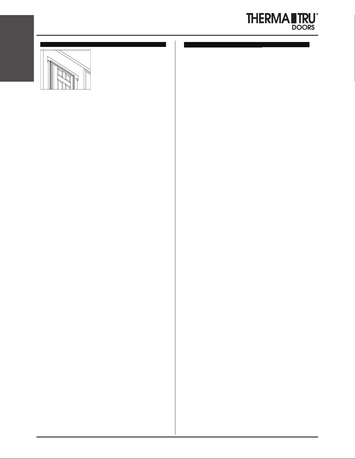
Paso 12: Impermeabilice, aplique un acabado y dé mantenimiento.
Proporcione y mantenga una cubierta de
goteo o un tapajuntas de dintel instalados de
forma adecuada para proteger la parte
superior de las superficies del ingreso de
agua y del daño. Coloque cinta adhesiva y
selle de manera adecuada la parte superior
de la lengüeta de la barrera resistente al
agua (WRB) sobre el tapajuntas del dintel.
Calafatee alrededor de todo el lado expuesto al clima del mód
ulo, sellando a
lo largo de la moldura de ladrillo hasta el material de tapajuntas o los paneles
de revestimiento y selle todas las uniones entre las jambas y las molduras.
Selle las uniones entre el reborde de los aditamentos exteriores y el frente de
la puerta para evitar la infiltración de aire y agua.
Coloque y ajuste clavos galvanizados para acabado a través de la moldura de
ladrillo, alred
edor del perímetro. Use tornillos para exteriores si va a instalar
una contrapuerta en la moldura de ladrillo. Avellane todos los sujetadores y
cúbralos con masilla para exteriores.
Añada material aislante a la cavidad entre la abertura y el módulo, a fin de
reducir la infiltración de aire y la transferencia de calor.
Se debe dar acabado a todas las puertas Therma-Tru® de fibra de vidrio
dentro
de 6 meses a partir de la instalación para una adecuada cobertura de la
garantía.
Pinte o tiña de acuerdo con las instrucciones de acabado de Therma-Tru®. No
pinte ni tiña el burlete, está ajustado para la fricción y se retira fácilmente para
pintar o teñir.
Se debe dar acabado a los 6 lados de las puertas. Se deben inspeccionar y dar
mantenimiento a todos los bordes de las puertas con la misma
regularidad que
a todas las demás superficies.
Se debe aplicar pintura base, pintura o tintes (una capa más una capa
superior), a todas las superficies de madera desnudas, como el marco para
puerta expuesto al clima, dentro de dos semanas a partir de la exposición para
lograr un mejor rendimiento.
Dé mantenimiento o reemplace los selladores y acabados tan pronto cualquier
deterioro sea evidente.
En el caso de la pintura brillante o semibrillante y de
las capas transparentes, hágalo cuando la superficie se vuelva opaca o áspera.
Los climas y las exposiciones más rigurosos necesitarán un mantenimiento
más frecuente.
Visite nuestro sitio Web www.thermatru.com para imprimir instrucciones de
instalación además de las instrucciones para el acabado de teñido SameDay®. También podrá ver nuestr
o video de solución de problemas para
resolver problemas menores en la instalación y para realizar ajustes.
Instrucciones para el acabado:
Trabaje sólo cuando las temperaturas se encuentren entre 10 y 32,2°C y
la humedad sea menor a un 85%. No aplique acabados bajo la luz solar
directa. Trabaje sólo en áreas bien ventiladas.
Módulos para puerta Smooth-Star®:
Para pintar puertas: Primero limpie con un detergente suave y agua o use
una solución de TSP (fosfato trisódico). Enjuague bien y deje secar
completamente. Proteja los aditamentos, los vidrios y los burletes antes de
pintar. Use pintura de látex acrílico de alta calidad para casas y siga las
instrucciones del fabricante para su aplicación. Use acabados para exteriores
para las superficies exteriores. Pinte los bordes y los extremos expuestos de la
puerta.
Para pintar marcos de vidrieras para puertas: Primero retire cualquier
exceso de sellador de vidrios rociando con un limpiador de ventanas o agua.
Use una navaja de un solo filo para desprender el sellador a lo largo del borde
del marco. Raspe el sellador del vidrio sosteniendo la cuchilla de la navaja en
un ángulo de 45 grados. Retire el residuo restante con un limpiador de
ventanas o aguarrás mineral. Limpie el marco del vidrio con un detergente
suave y agua o use una solución de TSP. Enjuague bien y deje secar
completamente. Proteja el vidrio. Aplique una pintura base de resina alquídica
o acrílica en los marcos de los vidrios. Deje secar la pintura base antes de
aplicar las capas de pintura de acabado. Use pintura de látex acrílico para
casas de alta calidad y siga las instrucciones del fabricante para su aplicación.
Use acabados para exteriores para las superficies exteriores.
Puertas Fiber-Classic®:
Para dar acabado a marcos de vidrieras para puertas y a accesorios para
paneles:
Primero retire cualquier exceso de sellador de vidrios rociando con un
limpiador de ventanas o agua. Use una navaja de un solo filo para desprender
el sellador a lo largo del borde del marco. Raspe el sellador del vidrio
sosteniendo la cuchilla de la navaja en un ángulo de 45°. Retire el residuo
restante con un limpiador de ventanas o aguarrás mineral. Limpie el marco del
vidrio con un detergente suave y agua o use una solución de TSP. Enjuague
bien y deje secar completamente. Proteja el vidrio. Aplique una pintura base
de resina alquídica o acrílica en los marcos de los vidrios. Deje secar la
pintura base antes de aplicar las capas de pintura de acabado. Use pintura de
látex acrílico de alta calidad para casas y siga las instrucciones del fabricante
para su aplicación y tiempo de secado. Use acabados para exteriores para las
superficies exteriores.
Para pintar puertas:
Primero limpie con un detergente suave y agua o use una solución de TSP
(fosfato trisódico). Enjuague bien y deje secar completamente. Aplique una
pintura base de resina alquídica o acrílica. Deje que la pintura base se seque
completamente, luego, pinte con pintura látex de casas siguiendo las
instrucciones del fabricante para su aplicación. Use una pintura base y una
pintura que sean compatibles. Use acabados para exteriores para las
superficies exteriores. Pinte los bordes y los extremos expuestos de la puerta.
Para teñir puertas:
Primero limpie con un paño limpio y aguarrás mineral y deje secar al aire o
lave la puerta con un detergente suave y agua o una solución de TSP (fosfato
trisódico). Enjuague bien y deje secar completamente. En el caso de las
superficies teñidas, sólo recomendamos el uso de tintes y productos de capas
transparentes que se encuentran en el kit para acabado Therma-Tru® SameDay® Stain. Aplique el tinte con un paño. Mientras más tiempo se deje el
tinte para “asentarse” antes de limpiarlo, más oscuro será el color. Use un
paño limpio para limpiar el tinte hasta lograr el tono que desea. Retire
cualquier exceso de tinte de las grietas del panel con la brocha de espuma que
se incluye. Deje secar el tinte durante al menos 6 horas antes de aplicar una
capa superior. Consulte las instrucciones del kit para acabado Therma-Tru®
Same-Day® Stain para obtener información detallada.
Pre-Hung Venting Unit Installation
Installation
1.18 2014 SITE 1
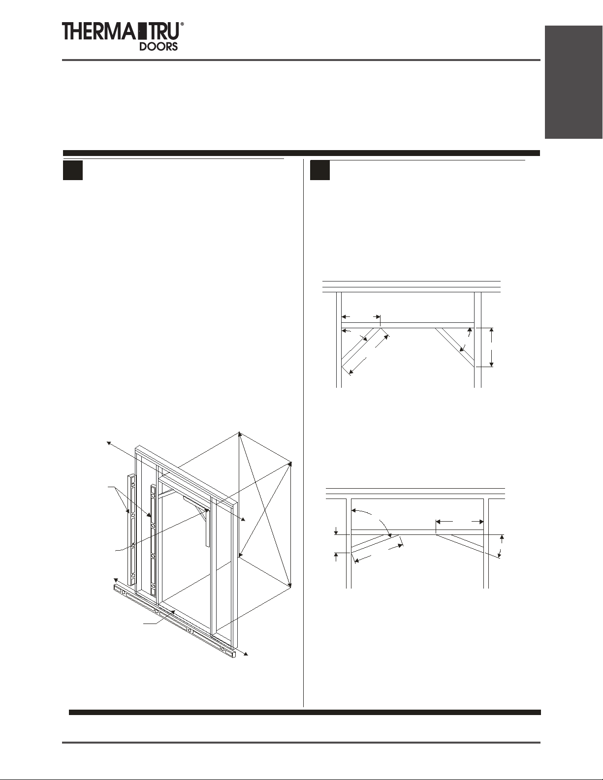
Pre-Hung Arch/Radius Unit Installation
Pre-hung Rustic Arch/Radius
Installation Instructions
Installation
1
CHECK AND PREPARE OPENING
1 2
•
Is subfloor level and solid? Provide a flat, level clean bearing
surface so the sill may be caulked and sealed to the opening.
Scrape, sand, or fill as required.
•
Shim subfloor for floor covering clearance if required. If
shimming, caulk under shims.
•
Is opening squar
Double-check by comparing diagonal measurements. Fix any
problems now.
•
Are framing and walls plumb? Use a 6-foot level and check both
sides of opening, both ways. Fix any problems now.
Are the wall surfaces around the opening on the same plane?
•
There must be no “warps” or “jogs”. Fix any problems now.
•
Is opening correct size? Check it against door frame
before installation. Opening should be
frame width plus ½” to 1”.
Wall straight?
e? Check all corners with a framing square.
size now
frame height plus ½” and
Compare Diagonals
SUPPORT FRAME CONSTRUCTION
2
Build support framing at top for radius/arched top head
jamb as shown below
Radius Top Head Jambs
11 9/32
45°
15 15/16
45°
11 9/32
Arch Top Head Jambs
70°
5 1/32
14 3/4
Refer to MSDRIST for all other Pre-Hanging Instructions
13 7/8
20°
Check
each side
both ways
Check all
four corners
with square
Check floor
under sill
q
E
E
q
u
a
Wall straight?
l
a
u
l
SITE 1 2014 1.19
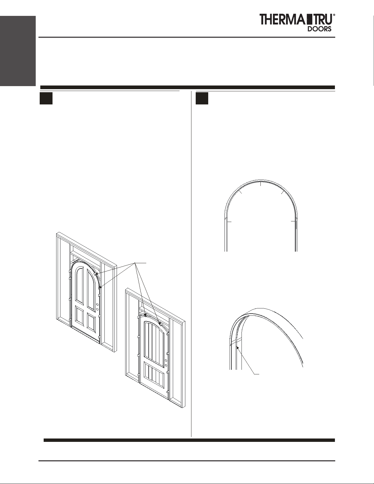
Pre-Hung Arch/Radius Unit Installation
1 1
Installation
Pre-hung Rustic Arch/Radius
Installation Instructions
SHIM BEHIND JAMBS, THEN ADJUST THE REST
OF THE FRAME
Go through another opening to work on swing side of door
•
•
Leave door fastened closed with transport clip
Shim at the indicated areas in the figure; Shim behind each hinge,
•
shim at the angled framing members at the top, and shim side
areas as shown
Recheck hinge jamb with a 6-foot level to ensure it is plumb and
•
straight
Adjust frame so the frame face is flush with door face all around
•
• Secure hinge jamb from the other side of the door. Set nails or
finish driving screws directly below shims
Due to varyi
•
the miter of the brick moulding where the radius/arch pi ece of the
head meets the straight leg of the side. This is expected and
should be caulked prior to painting.
ng dimensions of mouldings, there may be a gap at
3
SCREW INSTALLATION
43
Special Instructions For Radius Top Head Jambs:
••Use #10 x 2” wood screws
• Install screws in the order shown below.
Shims are required at all screw locations to control
the final shape of the radius and to allow for the
correct margins around the door.
3
4 5
1
2
Note:
Improper shimming WILL affect
the operation of the door unit.
Proper i
nstallation is necessary to
insure warranty coverage.
Top of door must be sealed with
paint or stain AND Topcoat. If not
finished the door warranty is
VOID!
Shim locations
(10 per door)
For Both Radius Top Head Jambs:
• Use #10 x 2” wood screws
• Position all screws in the location shown below.
The screws must be positioned such that the
weather-strip hides the screw heads.
Screw Position
Warning :
Modification or machining of this product can
release wood dust, a substance know to the State of
California to cause cancer.
Refer to MSDRIST for all other Pre-Hanging Instructions
P ar t# : M S D RA R R AD IS T6 5 R EV . B
© C o p yr ig h t 20 11 Th er m a- Tr u C o rp o ra t io n.
T he rm a -T ru D o o r s is a n o p e ra ti ng co m p a ny o f Fo r tu ne Br an d s, Inc .
3 /2 0
1.20 2014 SITE 1

Multi-Point Lock
Quick Tip Sheet & Instructions
Swing Door Handle Set Installation Instructions
A Phillips screwdriver is required.
A Hex wrench for set screws is
provided in the hardware package
To prevent damage to the handle set
while in the construction phase, use
the enclosed construction handle to
operate the door. Lift to engage
multipoint to close door. Push down
to open the door.
Use water to clean. Do not use brass
cleaner as it will remove the
protective coating. Brass Strike
Plates are Solid Brass and can be
polished as needed.
Note: Handles and backplates vary
by style but application is the same.
1. Apply the backplate gasket to the inside of the
exterior backplate. Push gaskets rmly into place to
ensure a tight seal. Attach interior and exterior
backplates to the door and fasten loosely with the
screws provided. Note: The screw heads must be
on the interior side of the door.
2. Mount nylon bushings to door gear handle hole on
interior and exterior backplates.
3. Insert the two piece handle shaft into one handle. Be
sure to orient the shaft as shown below. Screw the
set screw until ush with handle using the allen
wrench provided. Insert the handle with the shaft
through the backplate and door gear handle hole
until extending out opposite side of door.
4. Install remaining handle onto shaft, pressing tightly to
the backplates. Tighten the handle set screw with
the allen wrench. Screw until ush with handle.
5. Attach thumbturn to cylinder.
6. Insert the keyed cylinder from the interior side of the
door until it is ush with the exterior backplate. Install
the cylinder screw in the screw hole below the
deadbolt in the edge of the door. If passive deadbolt
will not turn, it is installed incorrectly. See Installation
Instructions for active & passive 90-Degree Cylinder.
Installation
Exterior
Lever Handle
Required Shaft
Position for Set
Screw
Mishandling
2” Phillips Head
Cylinder Screw
(One Provided)
Device
Exterior
Backplate
Gasket
7. Tighten the backplate screws.
Interior of
Door Stile
Gasket
Construction
Handle
Interior
Backplate
2” Phillips Head Brass Screws
(Two or Three Provided
Depending on the Backplate)
Nylon
Bushing
Lever Handle
Set Screw
(Two Provided)
Lock Cylinder
Thumbturn
Interior
SITE 1 2014 1.21
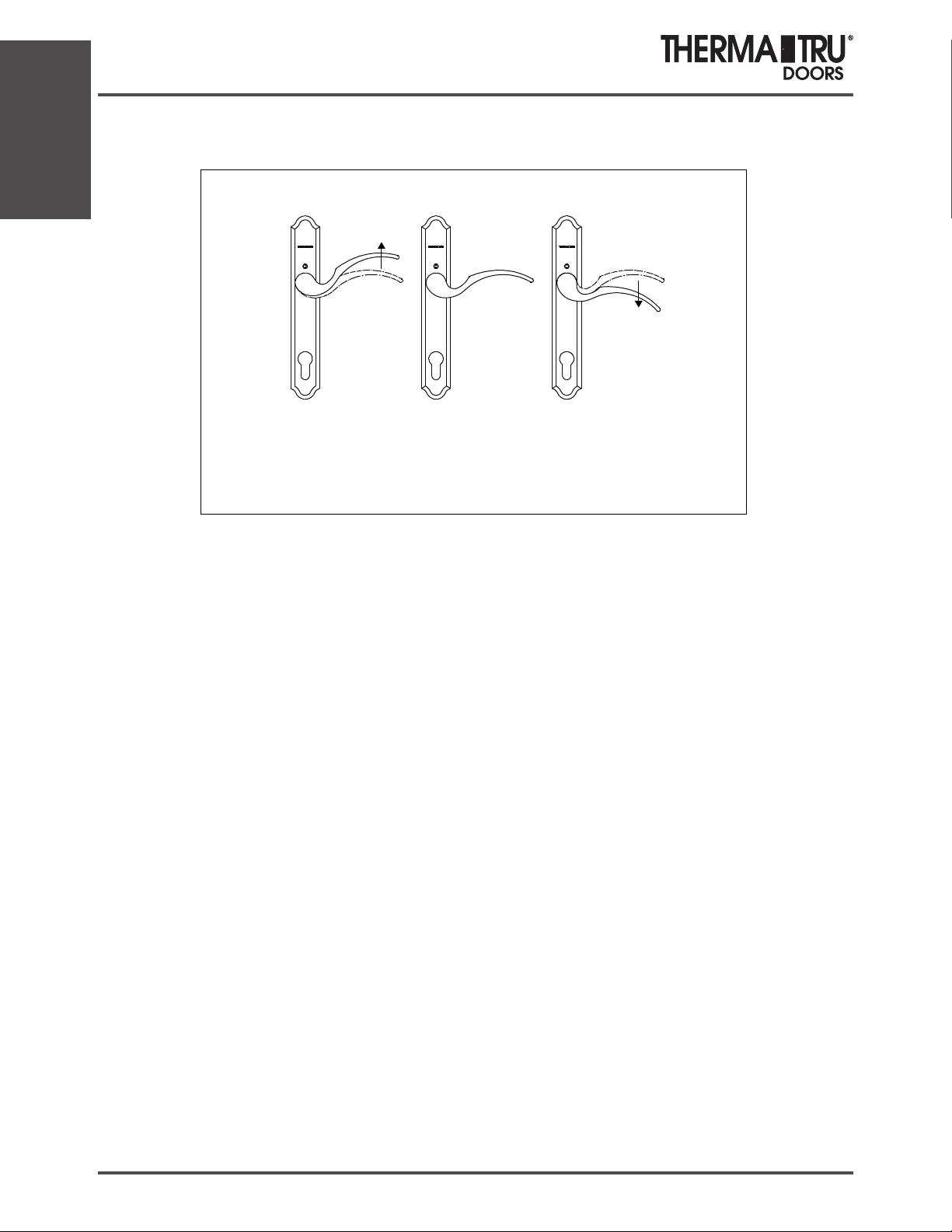
Installation
Multi-Point Lock
Quick Tip Sheet & Instructions
Swing Door Handle Operation Instructions
To lock system.
Lift handle to engage
multipoints prior to
engaging deadbolt.
Handle will
automatically
return to center
position.
To open door, disengage
deadbolt with key or
thumbturn, push handle
down to stop and
then open door.
Use key or thumbturn to
engage deadbolt.
TROUBLESHOOTING GUIDE
Note: To lock door, shootbolts, locking point tongues and deadbolt must all fully extend. Be certain door is square in frame before adjusting
other hardware. With the door in the open position, engage system by lifting handle and letting handle return to it’s center position. Extend
deadbolt by turning thumb turn. If the tongues or shootbolts extend and the deadbolt operates, the handle system is fully functional.
1. SYSTEM WILL NOT OPERATE WHEN YOU LIFT THE
HANDLE
Probable Cause: Improper installation of handle set.
Solution: Remove handle and reinstall.
See Handle Set Installation Instructions.
2. SYSTEM OPERATES IN THE OPEN POSITION WHEN YOU
LIFT HANDLE BUT NOT IN THE CLOSED POSITION WITH THE
DOOR SHUT
Probable Cause: Relationship of door in the frame.
Solution: Check to make sure door is square in the frame.
3. LOCKING POINTS DO NOT EXTEND
Probable Cause: Deadbolt is not fully extending.
Solution: Clear away anything blocking travel of deadbolt (insula-
tion, wood, etc.).
4. DEADBOLT WILL NOT FULLY ENGAGE
Probable Cause: Locking points are not fully engaged. System
design does not permit deadbolt operation unless locking points
are fully engaged.
Solution: Check system for binding problems. Conrm deadbolt
extends fully into strike. Check to conrm locking points are correctly engaging strikes on the frame.
6. SET SCREWS WILL NOT GO INTO HANDLE COMPLETELY
Probable Cause: Shaft is not assembled properly.
Solution: Remove handle to see how shaft is assembled. See
Handle Set Installation Instructions for proper assembly and position of shaft.
7. BOTTOM LOCKING POINT MOVES BUT TOP LOCKING
POINT DOES NOT
Probable Cause: Top extension drive rail is not connected to the
lock gear.
Solution: Remove screws used to attach top extension to the door
and the machine screw that attaches it to the lock gear, and remove top extension. Place the end of the drive rail (the “L” shape
in the lockcase above the latchbolt, as you slide the top extension
into the door. Fasten with a screw at the lockcase and one up
higher. Operate the gear to make sure it works. Finish installing
the remainder of the screws.
8. KEY DOES NOT WORK IN CYLINDER
Probable Cause: Cylinder was rekeyed incorrectly.
Solution: Check with Builder or Installer to see if cylinder was
rekeyed to match other doors in the house. If so, return to locksmith to rekey properly.
5. THUMBTURN OR KEY WILL NOT TURN
Probable Cause: Backplates may not be on straight
Solution: Conrm that inside and outside holes line up with lock-
case. Loosen backplate screws 1/2 turn.
1.22 2014 SITE 1
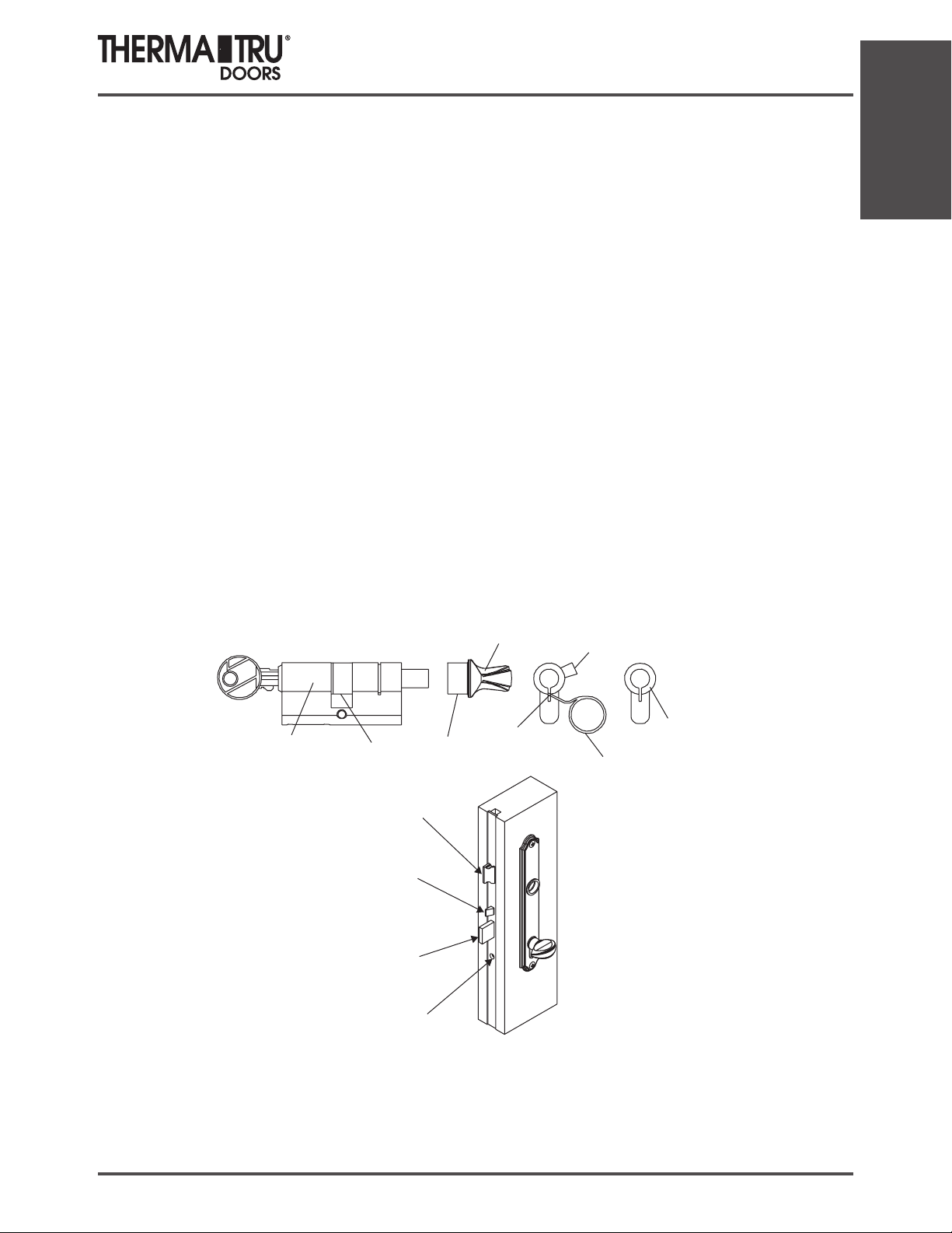
Multi-Point Lock
1994-2009 Therma-Tru Corp. All rights reserved. Therma-Tru is an operating company of Fortune Brands, Inc.
Quick Tip Sheet & Instructions
INSTALLATION INSTRUCTIONS FOR
ACTIVE AND PASSIVE 90-DEGREE CYLINDERS
1. The drive tab (A) must be aligned with the cylinder (B) to install the cylinder into the lock mechanism.
If the tab cannot be rotated to this position, push the pin (C) down with the ring wrench (D) by inserting
into the top of the slot (C), pushing inward and then pulling downward to disengage the stops. Turn the
knob (E) until the drive tab (A) is aligned with the cylinder (B).
2. Holding in this position, insert the cylinder body into door so the tab (A) on the cylinder is inside of the
lock.
3. Rotate the knob (E) towards the edge of the door so that the tab (A) moves inward toward the door
center, the tab (A) will seat properly and allow the deadbolt to extend. On the passive door, if the knob
is rotated in the wrong direction, it will rotate approximately 120 degrees and lock up the system. If this
happens, push the pin (C) down with the ring wrench (D) to disengage the stops and turn the knob (E)
in the opposite direction until the deadbolt extends.
4. NOTE: The passive door cylinder is shorter, has no key on the outside and no deadbolt to extend. If it is
properly locked, the handles do not operate.
5. Install cylinder screw into hole in edge of door.
6. If the set screw (F) is at the top of the knob, remove the set screw, reverse the knob 180 degrees and
reinstall so the set screw is at the bottom of the knob.
Installation
7. To remove cylinder, loosen and remove cylinder screw and repeat step 1 and slide cylinder from door.
E
A
B
B
A
F
C
D
LATCH
MISHANDLING
DEVICE
DEADBOLT
CYLINDER
SCREW
SITE 1 2014 1.23

Installation
Multi-Point Lock
Quick Tip Sheet & Instructions
HARDWARE MODIFICATION
INSTRUCTION SHEET
REMOVABLE
STICKER
SHIPPING CLIP
REMOVE CL IP
BEFOREUSE
Pull
REVERSING LATCH IS LATCH
IS BACKWARDS.
1. Pull out latch untillatch
clears lockcase.
2. Rotate latch 180 degrees
and release back into lockcase.
CAUTION:
Do not remove torx screws under any circumstances.
They are not afield serviceableitem.
SHIPPING CLIP FOR
MISHANDLING DEVICE
1. Remove sticker.
2. Remove shipping clip.
3. Make sure mishandling
4. If not, pull out and spin
device is sloped to engage
strike plate.
180 degrees.
SOCKET STRIKE INSTALLATION
1. Mark holelocation using tip
of shootbolts as guides.
2. Drill 9/16” holeatmarks
through jamb and sill.
3. Insert Socket Strike Cup
SOCKET
STRIKE
CUP
into 9/16” holes at head
jamb and sill.
NOTE: Door WILL NOT
lock unless bolts are fully
extended.
June 2009 Part# BMTTMPLQT
1.24 2014 SITE 1
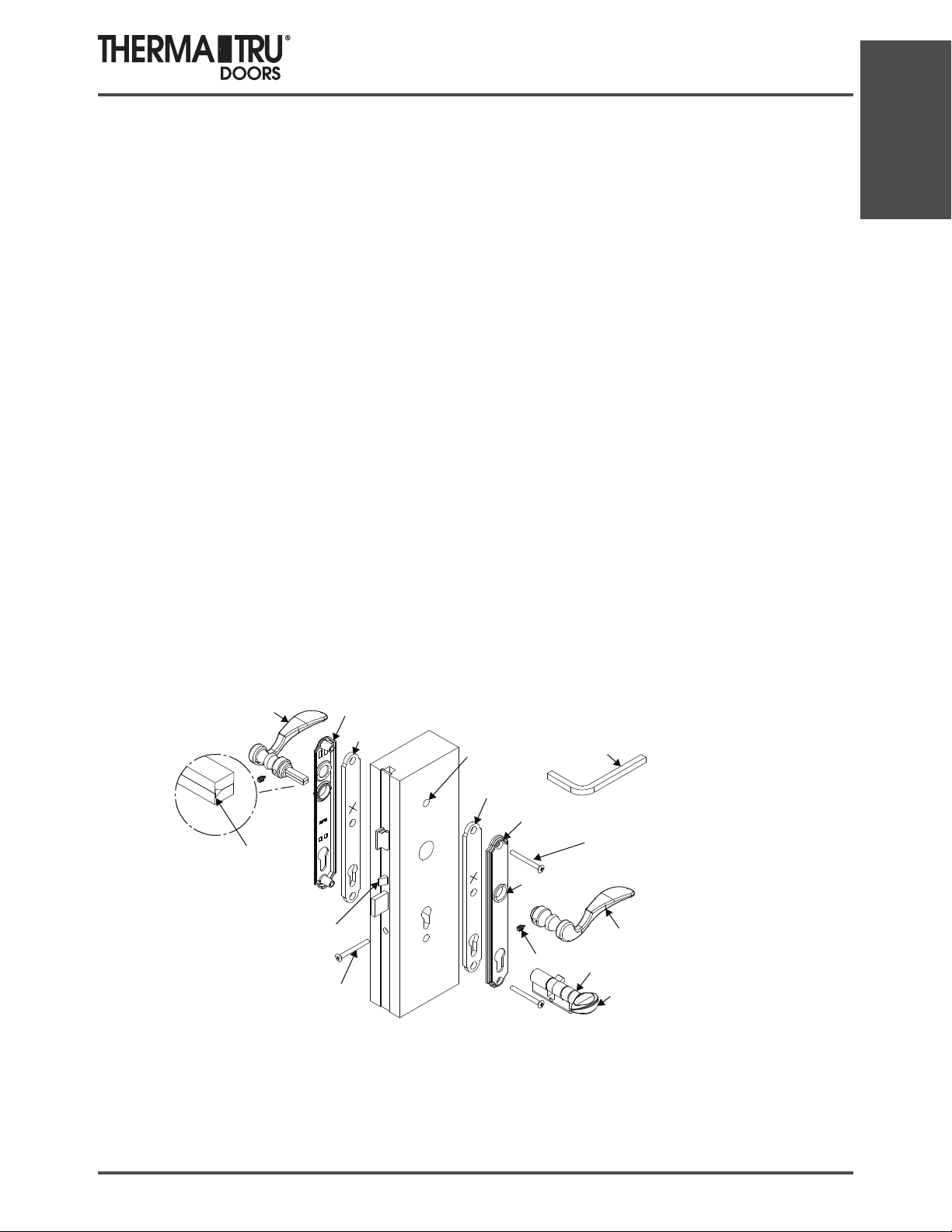
Multi-Point Lock
Quick Tip Sheet & Instructions
Instrucciones para el juego de manijas de puerta batiente
Necesita un destornillador Phillips
En el paquete de accesorios se
suministra una llave hexagonal para
tornillos de jación.
Para evitar el daño al juego de
manijas durante la fase de
construcción, utilice la manija de
construcción que se suministra para
hacer funcionar la puerta. Levante
para enganchar la cerradura
multipunto para cerrar la puerta.
Presione hacia abajo para abrir la
puerta.
Utilice agua para limpiar. No utilice
limpiador de latón porque retirará
el revestimiento protector. Las
placas de la cerradura son de latón
sólido y pueden pulirse según sea
necesario.
Nota: Las manijas y las placas
posteriores pueden variar de estilo
pero la aplicación es la misma.
1. Aplique la guarnición de la placa posterior a la parte
interior de la placa posterior externa. Presione las
guarniciones rmemente en su lugar para lograr un ajuste
adecuado. Fije las placas posteriores internas y externas a la
puerta y ajuste sin apretar con los tornillos que se suminis-
tran. Nota: Las cabezas de los tornillos deberán estar en el
lado interno de la puerta.
2. Monte los cojinetes de nailon en el agujero del mecanismo
de la manija de la puerta en las placas posteriores internas y
externas.
3. Inserte el eje de la manija de dos piezas en una manija.
Cerciórese de orientar el eje como se ilustra. Atornille el
tornillo de jación hasta que quede a ras con la manija
utilizando la llave Allen que se suministra. Inserte la manija
con el eje a través de la placa posterior y del agujero del
mecanismo de la manija de la puerta hasta que salga por el
lado opuesto de la puerta.
4. Instale la manija restante en el eje, presionando
rmemente en las placas posteriores. Apriete el tornillo de
jación de la manija con la llave Allen. Atornille hasta que
quede a ras con la manija.
5. Fije el cerrojo manual al cilindro.
6. Inserte el cilindro programado desde el lado interior de la
puerta hasta que quede a ras con la placa posterior externa.
Coloque el tornillo del cilindro en el agujero del tornillo
debajo de la cerradura de doble seguridad en el borde de la
puerta. Si la cerradura de doble seguridad pasiva no gira,
está instalada incorrectamente. Reérase a las instrucciones
de instalación para cilindros activos y pasivos de 90 grados.
Installation
Manija externa
tipo palanca
Posición necesaria
del eje para el
tornillo de fijación
Dispositivo
antimaltrato
Tornillo cilíndrico de
cabeza Phillips de
2” (5,1cm)
(Se suministra uno)
Placa posterior
externa
Guarnición
Interior del
montante de la
puerta
Guarnición
Placa posterior
interna
cojinete
de nailon
(Se suministran dos)
Manija
construcción
Tornillos de latón cabeza
Phillips de 2” (5,1cm)
(Se suministran dos o tres
dependiendo de la placa posterior)
Manija interna
tipo palanca
Tornillo de fijación
Cilindro de cerradura
Cerrojo manual
SITE 1 2014 1.25

Installation
Multi-Point Lock
Quick Tip Sheet & Instructions
Instrucciones de funcionamiento para la manija de puerta batiente
Para trancar el sistema.
Levante la manija para
enganchar los multipuntos
antes de enganchar la cerradura
de doble seguridad.
Utilice la llave o el cerrojo
manual para enganchar la
cerradura de doble seguridad.
HOJA DE INSTRUCCIONES DE MODIFICACIÓN
DE LOS ACCESORIOS METÁLICOS
ETIQUETA ENGOMADA
DESPRENDIBLE
SUJETADOR
ENVÍO
REMOVE CL IP
BEFOREUSE
Pull
La manija regresará
automáticamente
a la posición central.
SUJETADOR DE ENVÍO PARA
DISPOSITIVO ANTIMALTRATO
Para abrir la puerta,
desenganche la cerradura
de doble seguridad con la
llave o el cerrojo manual,
empuje la manija hacia
abajo para parar y luego
abra la puerta.
1. Retire la etiqueta engomada.
2. Retire el sujetador de envío.
3. Compruebe que el dispositivo
antimaltrato esté inclinado para
que enganche en la placa de la cerradura
4. Si no, saque y gire 180 grados.
CÓMO INVERTIR EL PICAPORTE SI
ESTÁ HACIA ATRÁS
1. Hale el picaporte hasta que salga
de la caja de la cerradura
2. Rote el picaporte 180 grados y deje
que regrese a la caja la cerradura.
1.26 2014 SITE 1

Multi-Point Lock
1994-2009 Therma-Tru Corp. Todos los derechos reservados. Therma-Tru Doors es una operacaión de Fortune Brands, Inc.
Quick Tip Sheet & Instructions
INSTRUCCIONES DE INSTALACIÓN PARA
CILINDROS ACTIVOS Y PASIVOS DE 90 GRADOS
1. La lengüeta impulsora (A) deberá estar alineada con el cilindro (B) para instalar el cilindro en el mecanismo
de tranca. Si la lengüeta no puede rotarse a esta posición, presione la clavija (C) hacia abajo con la llave de
aro (D) insertando en la parte superior de la ranura (C), presionando hacia adentro y luego halando hacia
abajo para desenganchar los topes. Gire la perilla (E) hasta que la lengüeta impulsora (A) esté alineada con el
cilindro (B).
2. Sosteniéndola en esta posición inserte el cuerpo del cilindro en la puerta de modo que la lengüeta (A) del
cilindro esté dentro de la cerradura.
3. Gire la perilla (E) hacia el borde de la puerta de modo que la lengüeta (A) se mueva hacia dentro hacia el centro de la puerta, la lengüeta (A) se asentará adecuadamente y permitirá que la cerradura de doble seguridad
se extienda. En la puerta pasiva, si la perilla se ha rotado en la dirección incorrecta, rotará aproximadamente
120 grados y trancará el sistema. Si esto ocurre, presione el pasador (C) hacia abajo con la llave de aro (D)
para desenganchar los topes y gire la perilla (E) en la dirección opuesta hasta que la cerradura de seguridad
se extienda.
4. NOTA: El cilindro de la puerta pasiva es más corto, no tiene llave en la parte externa y no tiene cerradura de
seguridad que se extienda. Si está adecuadamente cerrada, las manijas no funcionan.
5. Coloque el tornillo del cilindro en el agujero en el borde de la puerta.
6. ISi el tornillo de jación (F) está en la parte superior de la perilla, retire el tornillo de jación, reverse la perilla
180 grados y vuelva a instalar de modo que el tornillo de jación esté en la parte inferior de la perilla.
Installation
7. Para retirar el cilindro, aoje y retire el tornillo del cilindro, repita el paso 1 y saque el
E
B
A
F
C
A
D
PICAPORTE
DISPOSITIVO
ANTIMALTRATO
CERRADURADE
DOBLE SEGURIDAD
TORNILLO
DEL CILINDRO
B
SITE 1 2014 1.27

Installation
casquillo en los agujeros de 9/16” (1,4 cm)
Multi-Point Lock
Quick Tip Sheet & Instructions
GUÍA PARA LA LOCALIZACIÓN Y SOLUCIÓN DE PROBLEMAS
Nota: Para trancar la puerta, los pernos deslizantes, las lengüetas con punto de tranca y la cerradura de doble seguridad
deberán estar totalmente extendidos. Cerciórese de que la puerta esté a escuadra con el marco antes de ajustar los accesorios metálicos. Con la puerta en la posición abierta, enganche el sistema levantando la manija y dejando que regrese
a su posición central. Extienda la cerradura de doble seguridad girando el cerrojo manual. Si las lengüetas o los pernos
deslizantes se extienden y la cerradura de doble seguridad funciona, el sistema de manijas
está totalmente funcional.
1. EL SISTEMA NO FUNCIONA CUANDO LEVANTA LA
MANIJA
Causa probable: Instalación inadecuada del juego de
manijas.
Solución: Retire la manija y vuelva a instalar. Reérase a
las instrucciones de instalación del juego de manijas.
2. EL SISTEMA FUNCIONA EN LA POSICIÓN ABIERTA CUANDO LEVANTA LA MANIJA PERO NO EN LA
POSICIÓN CERRADA CON LA PUERTA TRANCADA
Causa probable: La relación de la puerta con el marco.
Solución: Verique para comprobar que la puerta esté a
escuadra con el marco.
3. LOS PUNTOS DE TRANCA NO SE EXTIENDEN
Causa probable: la cerradura de doble seguridad no se
extiende totalmente.
Solución: Despeje cualquier obstáculo que esté en el
camino de la cerradura de doble seguridad (aislante,
madera, etc.).
4. LA CERRADURA DE DOBLE SEGURIDAD NO ENGANCHA COMPLETAMENTE
Causa probable: Los puntos de tranca no están completamente enganchados El diseño del sistema no permite
el funcionamiento de la cerradura de doble seguridad a
menos que los puntos de tranca estén completamente
enganchados.
Solución: Revise el sistema en busca de problemas de
desplazamiento. Conrme que la cerradura de doble seguridad se inserta completamente en la hembra de la cerradura. Revise para conrmar si los puntos de trance están
enganchando correctamente en el marco.
5. EL CERROJO MANUAL O LA LLAVE NO GIRAN
Causa probable: Las placas posteriores puede que no
estén derechas
Solución: Conrme que los agujeros internos y externos
estén alineados con la caja de la cerradura. Aoje ½ vuelta
los tornillos de la placa posterior.
6. LOS TORNILLOS DE FIJACIÓN NO PENETRAN EN LA
MANIJA COMPLETAMENTE
Causa probable: El eje no está ensamblado adecuadamente.
Solución: Retire la manija para ver como está ensamblado
el eje. Reérase a las instrucciones de instalación del juego
de manijas para el ensamblaje adecuado y la posición del
eje.
7. EL PUNTO DE TRANCA INFERIOR SE MUEVE PERO
EL PUNTO SUPERIOR DE TRANCA NO
Causa probable: La barra impulsora de extension superior
no está conectada al mecanismo de la cerradura.
Solución: Retire los tornillos utilizados para jar la extensión superior a la puerta y el tornillo para metals que la ja
al mecanismo de la cerradura, y retire la extensión superior.
Coloque el extremo de la barra impulsora (la forma “L” de la
caja de la cerradura sobre el picaporte de resbalón, a medida que desliza la extensión superior en la puerta. Asegure
con un tornillo en la caja de la cerradura y otro más alto.
Haga funcionar el mecanismo para conrmar que trabaja
bien. Termine de colocar el resto de los tornillos.
8. LA LLAVE NO FUNCIONA EN EL CILINDRO
Causa probable: El cilindro fue reprogramado incorrectamente.
Solución: Revise con un constructor o instalador para comprobar si el cilindro fue reprogramado igual que las otras
puertas de la casa. Si es así, regrese a la cerrajería para
que se lo reprogramen adecuadamente.
INSTALACIÓN DE LA HEMBRA DEL CASQUILLO
1. Marque la ubicación del agujero utilizando
la punta del perno deslizante como guÌa.
2. Taladre agujeros de 9/16” (1,4 cm) en las
marcas a través de la jamba y la solera.
3. Inserte el receptáculo de la hembra del
RECEPTÁCULODELA
HERBRADEL CASQUILLO
en la jamba superior y la solera.
NOTA: la puerta NO trancará a menos que
ambos pernos estén totalmente extendidos.
Junio 2009 Numero de parte de BMTTMPLQT
1.28 2014 SITE 1
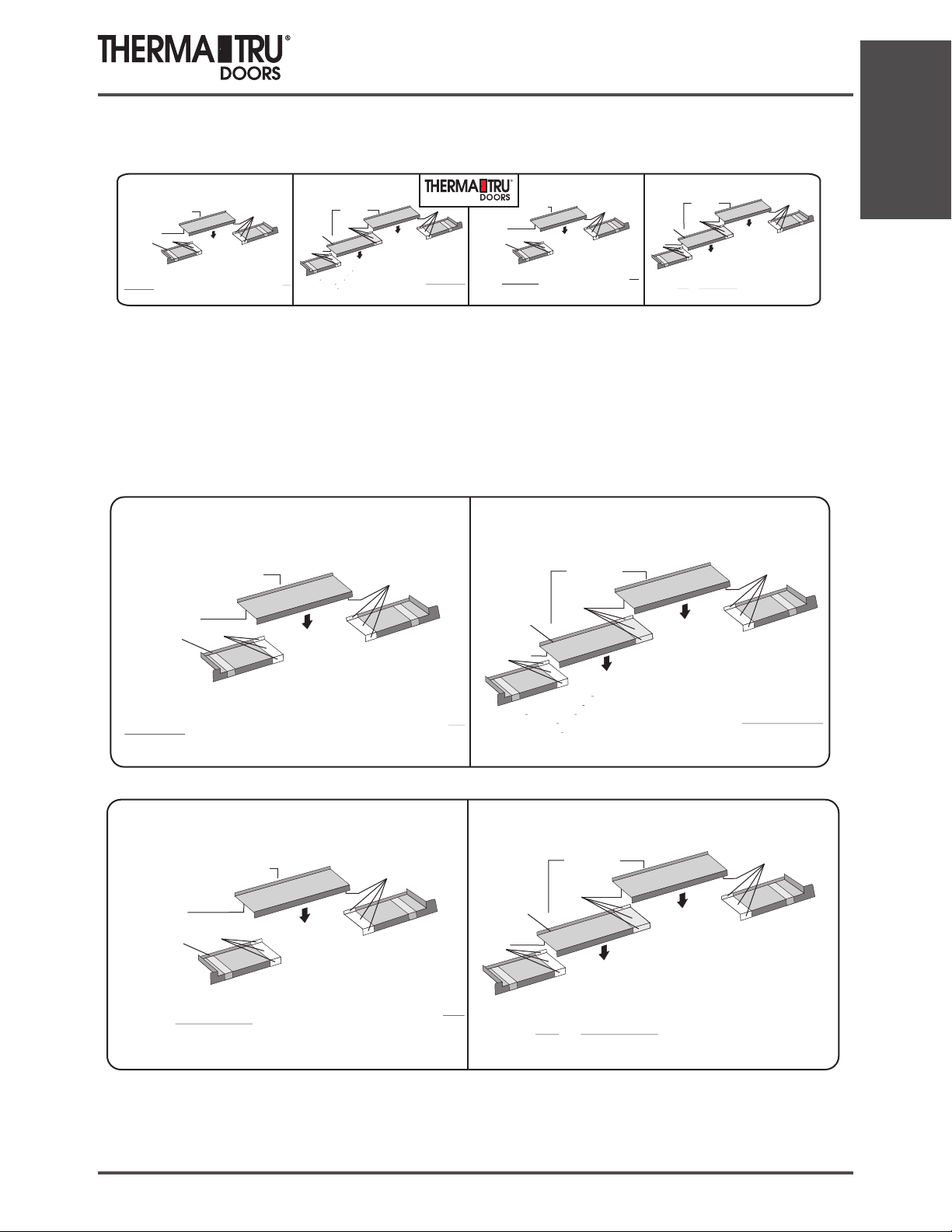
Sill Pan Installation Instructions
Installation
SINGLE PIECE
CENTER SECTION
(Openings less than 52 1/2”)
Center section
Apply PVC cement
to the overlap
areas of the center
piece.
Run a bead of
Apply
Sealant along the
PVC cement
interior edge of the
sill pan to prevent
air infiltration.
Left end piece
needed. On the sub-floor, where the sill pan will be positioned, apply 3 very large beads of
Elastomeric or Polyurethane sealant across the entire width of the opening. Place end pieces
tightly against the sides of the rough opening. Liberally coat the underside of the center section
where it overlaps the end pieces and the recessed areas of the end pieces with the provided
CEMENT ONLY
the colder temperatures require longer bonding times.
bead of sealant along the lower interior edge of the pan. Install door unit into pan.
joint. Check the center sections(s)for proper length and trim as
. Hold pieces together long enough to ensure a good bond.
sealant to the bottom of sill when using a sill pan.
Apply PVC cement
Right end piece
Dry fit the pan in the rough opening
making sure you have at least 2” of overlap at each
Keep in mind that
To prevent air infiltration, run a small
Do not apply
Install door unit into sill pan.
PVC
MULTIPLE PIECE
CENTER SECTION
Center sections
Apply PVC cement
to the overlap
areas of the center
Run a bead of
pieces.
sealant along the
interior edge of the
sill pan to prevent
air infiltration.
Apply
PVC cement
sub-floor,where the sill pan will be positioned, apply 3 very large beads of
Elastomeric or Polyurethane sealant across the entire width of the opening. Place
Left
end
end pieces tightly against the sides of the rough opening. Liberally coat the overlapped
piece
areas and the recessed areas of the end pieces with the provided
PVC CEMENT ONLY.
Hold pieces together long enough to ensure a good bond
. Keep in mind that colder
temperatures require longer bonding times.
sealant along the lower interior edge of the pan
. Do not apply sealant to the bottom of sill
For large rough openings, the center section
may be in multiple pieces which overlap to form a
continuous pan. Dry fit the pan in the rough opening
making sure you have at least 2” of overlap at each joint. Check the
center section(s) for proper length and trim as needed. On the
To prevent air infiltration, run a small bead of
Install door unit into sill pan.
when using a sill pan.
Apply PVC cement
Label enlarged for clarity.
SINGLE PIECE
CENTER SECTION
(Openings less than 52 1/2”)
Center section
Apply PVC cement
to the overlap
areas of the center
Run a bead of
Sealant along the
interior edge of the
sill pan to prevent
air infiltration.
Elastomeric or Polyurethane sealant across the entire width of the opening. Place end pieces
tightly against the sides of the rough opening. Liberally coat the underside of the center section
where it overlaps the end pieces and the recessed areas of the end pieces with the provided
CEMENT ONLY.
the colder temperatures require longer bonding times.
bead of sealant along the lower interior edge of the pan. Install door unit into pan.
piece.
Apply
PVC cement
Left end piece
needed. On the sub-floor, where the sill pan will be positioned, apply 3 very large beads of
making sure you have at least 2” of overlap at each
joint. Check the center sections(s)for proper length and trim as
Hold pieces together long enough to ensure a good bond.
sealant to the bottom of sill when using a sill pan.
Apply PVC cement
Right end piece
Dry fit the pan in the rough opening
To prevent air infiltration, run a small
Keep in mind that
Install door unit into sill pan.
Do not apply
SECCIÓN CENTRAL DE
(Aberturas de menos de 133,35 cm)
Sección central
Aplique cemento para
PVC en las areas
superpuestas de la pieza
central.
Aplique cemento
Extienda un cordón
Right end piece
para PVC
de masilla de calafateo
a lo largo del borde
interior del resevestimiento
de aire
Pieza del extremo
izquierdo
córtelas. En el subsuelo, en el lingae en donde se colocará el revestimiento, aplique 3 cordones muy
anchos de sellador elastomérico o de poliurethano a lo largo de todo el ancho de la abertura. Coloque las
piezas extremos muy pegados contra los lados de la abertura sin terminar. Cubra generosamente y
CEMENTO PARA PVC
con el incluido el lado inferior de la pieza central, en ligar en donde se
superpongan las piezas de los extremos y las áreas de ranuras de las piezas extremos. Mantenga juntas
el tiempo suficente para asegurar la formación de una buena adhesíon. Recuerde que las temperaturas
bajas requieren mayores tiempos de adhesíon. Para evitar la filtracion de aire, extienda un cordón
de masilla de calafateo pequeño a lo largo del borde interior inferior del revestimiento. Instale la puerta
en el revestimiento. No calafatee la parte inferior del alféizar si utiliza este revestimiento para alféizar.
cm de superposición en cada unión. Comprube que la o
las secciones centrales tenga el largo adecuado y, de ser necesario,
MULTIPLE PIECE
CENTER SECTION
Run a bead of
sealant along the
interior edge of the
sill pan to prevent
air infiltration.
Apply
PVC cement
Elastomeric or Polyurethane sealant across the entire width of the opening. Place
end pieces tightly against the sides of the rough opening. Liberally coat the overlapped
areas and the recessed areas of the end pieces with the provided
Hold pieces together long enough to ensure a good bond
temperatures require longer bonding times.
sealant along the lower interior edge of the pan
. Do not apply sealant to the bottom of sill
PVC
Left
end
piece
UNA PIEZA
Aplique cemento para PVC
Pieza del extremo derecho
Ajuste el revestimiento en seco en la abertura
sin terminar, asegurándose de dejar al mneos 5,07
Center sections
Apply PVC cement
to the overlap
areas of the center
pieces.
Extienda un cordón de
masilla de calafateo a lo
largo del borde interior
del revestmiento del
alféizar para la
filtración de aire.
Aplique cemento
para PVC
Pieza
del extremo
izuierdo
SÓLO
sin terminar. Cubra generosamente las áreas superpuestas y las areas con ranuras de las piwezas de
suficiente para asegurar la formacion de una buena adhesión. Para evitar la filtración de aire, extienda
un cordon de masilla de calafateo pequeño a lo largo del borde interior inferior del revestimiento. No
SECCIÓN CENTRAL DE
VARIAS PIEZAS
Sección central
Aplique cemento para
PVC en las áreas
superpuestas de la
pieza central.
Para aberturas sim terminar grandes, la sección central
puede formarse de varias piezas que se superponen para
formar un revestimiento continuo. Ajuste el revestimiento en
seco en la abertura sin terminar, asegurándose de dejar al menos
5,08 cm de superposicion en cada unión. Compriebe que la o las
secciones centrales tenga el largo adecuado y, de ser necesario, cortelas.
En el subsuelo, en el lugar en donde se colocará el revestimiento, aplique 3 cordones
muy anchos de sellador elastomérico o de poliuretano a lo largo de todo el ancho de la
abertura. Coloque las piezas de los extremos muy pegados contra lo lados de la abertura
los extremos con el incluido. Mantenga juntas las piezas el tiempo
SÓLO CEMNETO PARA PVC
calafatee la parte inferior del alféizer si utiliza este reservestimiento para alféizar.
Aplique cemento
para PVC
Pieza del extremo
derecho
Apply PVC cement
Right end piece
For large rough openings, the center section
may be in multiple pieces which overlap to form a
making sure you have at least 2” of overlap at each joint. Check the
sub-floor, where the sill pan will be positioned, apply 3 very large beads of
PVC CEMENT ONLY.
. Keep in mind that colder
continuous pan. Dry fit the pan in the rough opening
center section(s) for proper length and trim as needed. On the
To prevent air infiltration, run a small bead of
when using a sill pan.
Install door unit into sill pan.
SECCIÓN CENTRAL DE
UNA PIEZA
(Aberturas de menos de 133,35 cm)
Sección central
Aplique cemento para
PVC en las areas
superpuestas de la pieza
central.
Extienda un cordón
de masilla de calafateo
a lo largo del borde
interior del resevestimiento
de aire
Pieza del extremo
izquierdo
córtelas. En el subsuelo, en el lingae en donde se colocará el revestimiento, aplique 3 cordones muy
anchos de sellador elastomérico o de poliurethano a lo largo de todo el ancho de la abertura. Coloque las
piezas extremos muy pegados contra los lados de la abertura sin terminar. Cubra generosamente y
con el incluido el lado inferior de la pieza central, en ligar en donde se
superpongan las piezas de los extremos y las áreas de ranuras de las piezas extremos. Mantenga juntas
el tiempo suficente para asegurar la formacion de una buena adhesión. Recuerde que las temperaturas
bajas requieren mayores tiempos de adhesión. Para evitar la filtracion de aire, extienda un cordón
de masilla de calafateo pequeño a lo largo del borde interior inferior del revestimiento. Instale la puerta
en el revestimiento. No calafatee la parte inferior del alféizar si utiliza este revestimiento para alféizar.
Aplique cemento
para PVC
las secciones centrales tenga el largo adecuado y, de ser necesario,
CEMENTO PARA PVC
Ajuste el revestimiento en seco en la abertura
sin terminar, asegurándose de dejar al mneos 5,07
cm de superposición en cada unión. Comprube que la o
Aplique cemento para PVC
Pieza del extremo derecho
Extienda un cordón de
masilla de calafateo a lo
largo del borde interior
del revestmiento del
alféizar para la
filtración de aire.
Aplique cemento
para PVC
Pieza
del extremo
izuierdo
SÓLO
sin terminar. Cubra generosamente las áreas superpuestas y las areas con ranuras de las piwezas de
suficiente para asegurar la formacion de una buena adhesión. Para evitar la filtración de aire, extienda
muy anchos de sellador elastomérico o de poliuretano a lo largo de todo el ancho de la
abertura. Coloque las piezas de los extremos muy pegados contra lo lados de la abertura
los extremos con el incluido. Mantenga juntas las piezas el tiempo
un cordón de masilla de calafateo pequeño a lo largo del borde interior inferior del revestimiento. No
SECCIÓN CENTRAL DE
VARIAS PIEZAS
Aplique cemento
Sección central
Aplique cemento para
PVC en las áreas
superpuestas de la
pieza central.
Para aberturas sim terminar grandes, la sección central
puede formarse de varias piezas que se superponen para
formar un revestimiento continuo. Ajuste el revestimiento en
seco en la abertura sin terminar, asegurándose de dejar al menos
5,08 cm de superposicion en cada unión. Compriebe que la o las
secciones centrales tenga el largo adecuado y, de ser necesario, cortelas.
En el subsuelo, en el lugar en donde se colocará el revestimiento, aplique 3 cordones
SÓLO CEMNETO PARA PVC
calafatee la parte inferior del alféizer si utiliza este reservestimiento para alféizar.
para PVC
Pieza del extremo
derecho
SITE 1 2014 1.29
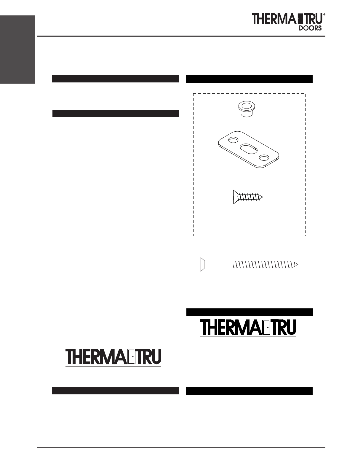
Installation
Paintable & Stainable Astragal
Site Installation Instructions
Astragal Site Pack Contents
100-204188
Fill Plug
Site
Installation
Instructions
for
Aluminum
Astragal
The following instructions are for steps
which can be completed in the shop or
at the site after unit installtion.
If the following steps are to be done at
the site, the Astragal Site Pack along with
these instructions should be attached to
the pre-hung unit.
If the following steps are done in the shop,
attach this instruction sheet along with the
(8) long hinge screws to the pre-hung unit.
Read all instructions before starting.
The Most Preferred Brand in the Business
Stock# 5134141
Keeper Plate
(2) #6 x 1”
Phillips Flat Head
Keeper Plate Screws
(8) #10 x 2-1/2”
Phillips Flat Head
Hinge Screws - Jamb Leaf
®
The Most Preferred Brand in the Business
®
1750 Indian Wood Circle
Maumee, Ohio 43537
419-891-7400
©1994-2004 Therma-Tru Corp. All rights reserved.
Therma-Tru Doors is an operating company of Fortune Brands, Inc.
1.30 2014 SITE 1

Paintable & Stainable Astragal
APPLY SEALANT AND MARK SLIDE
1
BOLT ENDS.
Extend slide bolts and place sealant on each tip.
Sealant will be used to mark hole locations.
Retract bolt.
With inactive door held in closed position, and
door flush with frame, extend slide bolts to mark
head and sill.
Retract bolts.
Site Installation Instructions
DRILL HEAD AND SILL BOLT HOLES.
2
Open door and drill 3/8” diameter
hole at overhead in wood frame.
Drill 7/16” diameter hole through
threshold.
Fill threshold hole with sealant.
Installation
Rev. 11/19/02
SITE 1 2014 1.31

Installation
Paintable & Stainable Astragal
Site Installation Instructions
INSERT ASTRAGAL FILL PLUG INTO
3
THRESHOLD.
Fit should be tight, sealant will
act as adhesive.
Fill Plug
INSTALL KEEPER PLATE.
4
INSTALL LONG HINGE SCREWS
5
(SITE ONLY).
With door open,
at hinges where
labels indicate,
drill 1/8” dia.
pilot holes
and drive
#10 x 2-1/2”
screws through
hinges to anchor
door frame and
prevent sagging.
#10 x 2-1/2”
screws
(2)
Position brass keeper plate as shown at
overhead hole.
Fasten plate with (2) #6 x 1” screws.
Astragal Keeper Plate
with
#6 x 1” screws
(1)
(1)
1.32 2014 SITE 1

Multi-Point Shootbolt Paintable &
Stainable Astragal Installation Instructions
100-204195
Multi-Point
Shootbolt
Astragal
Assembly &
Multi-Point Astragal Pack Contents
Hex Key
(9) #10 x 1 1/2”
Phillips Pan Head
Corner Seal Pad
Astragal Mounting
Screws
Installation
Installation
Instructions
The following instructions are for steps
which can be completed in the shop
or at the site after unit installation for
Double Door units
with Multi-Point Locks
Read all instructions before starting.
The Most Preferred Brand in the Business
Rev.D 8/17/04
®
Stock# 5134143
(8) #10 x 2-1/2”
Phillips Flat Head
Hinge Screws - Jamb Leaf
Strike Plates and Strike Plate Fasteners
do not come with the astragals. They are
purchased separately. Contact your
Therma-Tru Customer Relations
Representative for the
correct strike plate package.
®
The Most Preferred Brand in the Business
1750 Indian Wood Circle
Maumee, Ohio 43537
419-891-7400
©1994-2004 Therma-Tru Corp. All rights reserved.
Therma-Tru Doors is an operating company of Fortune Brands, Inc.
SITE 1 2014 1.33

Installation
Multi-Point Shootbolt Paintable &
Stainable Astragal Installation Instructions
SET ASTRAGAL ON DOOR.
1
NOTE: If deadbolt is used, deadbolt
strike boss should be removed. Press thru back
of astragal or slide to latch position and remove.
Align astragal to slab which is to be “fixed”.
Index end of aluminum
to bottom edge of slab
to make flush with
bottom of door.
NOT
#10 x 1 1/2”
pan head
screws
DRILL AND SECURE ASTRAGAL.
2
Pre-drill for mounting thru the astragal mounting
holes into the fixed door using 1/8” dia. bit.
For astragal with 17” slide bolts, once the top and
bottom holes have been pre-drilled, install
#10 x 1-1/2” mounting screws. Then loosen the set
screws in the retainers, place flush with the ends,
and re-tighten set screws. Pre-drill remaining holes
and install remaining #10 x 1-1/2” mounting screws.
(Note: upper and lower mounting screws also
secure the bolt spring clip.)
#10x1-1/2”
Pan Head Screw
Retainer
Bolt
1.34 2014 SITE 1

Multi-Point Shootbolt Paintable &
Snap-in Cover
Stainable Astragal Installation Instructions
FASTEN STRIKE PLATE ASSEMBLY.
3
(Sold Separately)
Position latch/deadbolt strike plate
in mortised pocket on astragal using
screws provided in Multi-Point Strike
Plate Package
APPLY SNAP-IN COVER.
4
Align longer snap-in cover with top of
strike plate and snap into place. Trim to
length of astragal.
Align shorter snap-in cover with bottom of
strike plate and snap into place. Trim to
length of astragal.
Installation
Latch/
Deadbolt
Strike
Plate
Corner
Seal Pad
APPLY CORNER SEAL PAD.
5
CAUTION:
Corner seal pads are only used
with inswing units.
Apply corner seal pad against weatherstrip with
bottom edge in line with bottom edge of seal.
INSTALL LONG HINGE SCREWS
6
(SITE ONLY).
With door open,
at hinges where
labels indicate,
drill 1/8” dia.
Pilot holes
and drive
#10 x 2-1/2”
(2-top,
1-middle,
1-bottom)
screws through
hinges to anchor
door frame and
prevent sagging.
#10 x 2-1/2”
screws
SITE 1 2014 1.35

Installation
Coastal Astragal 2 Installation Instructions
APPLY SEALANT AND MARK SLIDE
Site
1
BOLT ENDS.
Installation
Instructions
for
Coastal
Astragal 2
The following instructions should be completed
at the unit installation site.
The hardware pack contains all the necessary
hardware and fasteners needed to complete this
installation.
Extend slide bolts and place sealant on each tip.
Sealant will be used to mark hole locations.
Retract bolt.
With inactive door held in closed position, and
door flush with frame, extend slide bolts to mark
head and sill.
Retract bolts.
Read all instructions before starting.
®
The Most Preferred Brand in the Business
Rev. A 3/8/06
1.36 2014 SITE 1
P/N: CA2STIS

Coastal Astragal 2 Installation Instructions
Installation
DRILL HEAD AND SILL BOLT HOLES.
2
Open door and drill 3/8” diameter hole at overhead
in wood frame 2” deep.
Drill 1/2” diameter hole through threshold 2-1/4”
deep. If sub-floor material is masonry, a 1/2” diameter
masonry drill bit will be needed to complete hole.
Apply significatnt amount of sealant to threshold
hole to seal sub-floor interface area.
INSERT ASTRAGAL FILL PLUG INTO
3
THRESHOLD.
Apply additional sealant to underside of lip of
sill plug.
Fit should be tight, sealant will act as adhesive.
Deep Sill Plug
INSTALL KEEPER PLATES.
4
Rev. 12/20/02
Position keeper plates as shown at
overhead and sill holes.
Fasten plates with (2) #8 x 2-1/2” screws.
Astragal Keeper Plates
with
#8 x 2-1/2” screws
SITE 1 2014 1.37

Installation
Coastal Astragal 2 Installation Instructions
Coastal Astragal 2 Site Pack Contents
INSTALL LONG HINGE SCREWS.
5
With door open,
at hinges where
labels indicate,
drill 1/8” dia.
pilot holes
and drive
#10 x 2-1/2”
screws through
hinges to anchor
door frame and
prevent sagging.
#10 x 2-1/2”
screws
(2)
(2) Keeper Plate
(4) #8 x 2-1/2”
Phillips Flat Head
Keeper Plate Screws
(10) #10 x 2-1/2”
Phillips Flat Head
Deep Sill Plug
8/0 doors will follow
(2 at top, 1, 1, 1) hinge screw
installation configuration.
(1)
(1)
Therma-Tru is a registered trademark of Therma-Tru Corp.
© 2006 Therma-Tru Corp.
Hinge Screws - Jamb Leaf
®
The Most Preferred Brand in the Business
1750 Indian Wood Circle
Maumee, Ohio 43537
419-891-7400
1.38 2014 SITE 1

Multi-Point Shootbolt
Coastal Astragal 2 Installation Instructions
Site
Installation
Instructions
for
Multi-Point
APPLY SEALANT AND MARK SLIDE
1
BOLT ENDS.
Extend slide bolts and place sealant on each tip.
Sealant will be used to mark hole locations.
Retract bolt.
With inactive door held in closed position, and
door flush with frame, extend slide bolts to mark
head and sill.
Retract bolts.
Installation
Shootbolt
Coastal
Astragal 2
The following instructions should be completed
at the unit installation site.
The hardware pack contains all the necessary
hardware and fasteners needed to complete the
installation of the astragal unit.
Read all instructions before starting.
®
The Most Preferred Brand in the Business
Rev. A 3/8/06
SITE 1 2014 1.39
P/N: CA2MPLSSITE
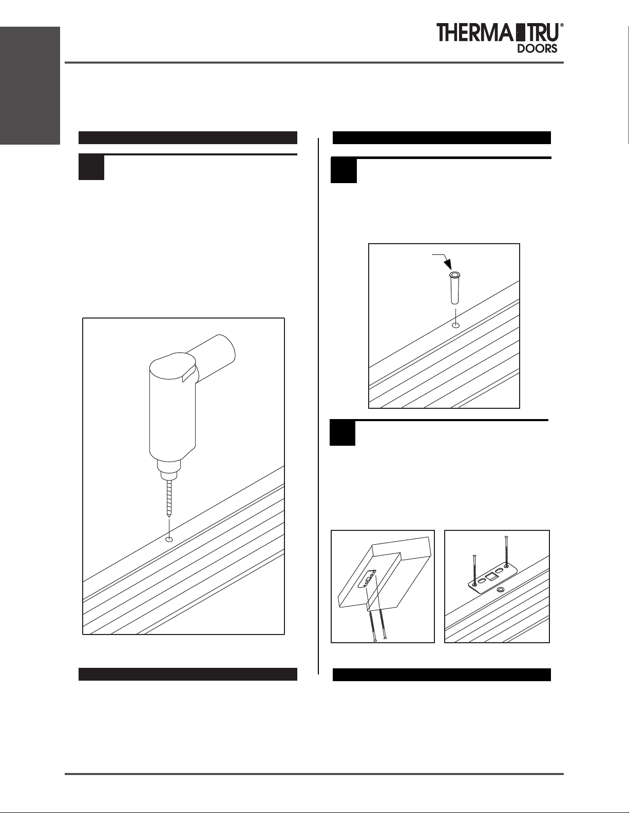
Installation
Multi-Point Shootbolt
Coastal Astragal 2 Installation Instructions
DRILL HEAD AND SILL BOLT HOLES.
2
Open door and drill 3/8” diameter hole at overhead
in wood frame 2” deep.
Drill 1/2” diameter hole through threshold 2-1/4”
deep. If sub-floor material is masonry, a 1/2” diameter
masonry drill bit will be needed to complete hole.
Apply significatnt amount of sealant to threshold
hole to seal sub-floor interface area.
INSERT ASTRAGAL FILL PLUG INTO
3
THRESHOLD.
Apply additional sealant to underside of lip of
sill plug.
Fit should be tight, sealant will act as adhesive.
Deep Sill Plug
INSTALL KEEPER PLATES.
4
Rev. 12/20/02
Position keeper plates as shown at
overhead and sill holes.
Fasten plates with (2) #8 x 2-1/2” screws.
Astragal Keeper Plates
with
#8 x 2-1/2” screws
1.40 2014 SITE 1

Multi-Point Shootbolt
Coastal Astragal 2 Installation Instructions
INSTALL LONG HINGE SCREWS.
5
With door open,
at hinges where
labels indicate,
drill 1/8” dia.
pilot holes
and drive
#10 x 2-1/2”
screws through
hinges to anchor
door frame and
prevent sagging.
Installation
Coastal Astragal 2 Site Pack Contents
#10 x 2-1/2”
screws
Deep Sill Plug
(4) #8 x 2-1/2”
Phillips Flat Head
8/0 doors will follow
(2 at top, 1, 1, 1) hinge screw
installation configuration.
(1)
(1)
(2)
Keeper Plate Screws
(10) #10 x 2-1/2”
Phillips Flat Head
Hinge Screws - Jamb Leaf
Strike Plates and Strike Plate Fasteners do not
come with the astragals. They are purchased
separately. Contact your Therma-Tru Customer
Relations Representative for the correct strike
plate package.
®
The Most Preferred in the Business
1750 Indian Wood Circle
Maumee, Ohio 43537
419-891-7400
Therma-Tru is a registered trademark of Therma-Tru Corp.
© 2006 Therma-Tru Corp.
SITE 1 2014 1.41

French Door System Outswing
Astragal Security Cover Installation
Installation
Attach Outswing Astragal Security Cover (Optional)
(Not available for Coastal Astragal applications.)
7/8” Aluminum Outswing
Astragal Security Cover (Optional)
Fasten with (9) #8 x 5/8” Phillips pan head
stainless steel screws.
Active Door7/8” Astragal
1.42 2014 SITE 1

Transom Installation Instructions
Installation Instructions
for
Transom Units
Installation
Single Door Mulled Sidelite
Mulled Sidelites
Separated Sills
Mulled Sidelites
Separated Sills
Mulled Sidelites
Separated Sills
Read all instructions before starting.
Continuous Head/Sill
Patio Patio
and Mullions
Continuous Head/Sill
and Mullions
SITE 1 2014 1.43

Installation
Transom Installation Instructions
ASSEMBLE JAMB EXTENDERS IF
1
USING 6-5/8” JAMBS.
Measure transom frame width and height.
The following are recommended height and width
dimensions. Use actual measurements to construct
jamb extender frame.
Height: 13-15/32"
Door/Sidelite Slab Width
14” Sidelite 14”
12” Sidelite
3/0
5/0 Patio
5/4 Patio
5/8 Patio
6/0 Patio
3/0 w/12” S/L, Mulled
3/0 w/12” S/L, Boxed.
3/0 w/14” S/L, Mulled
3/0 w/14” S/L, Boxed
12”
36-5/32”
64-5/16”
68-5/16”
72-5/16”
76-5/16”
62-5/32”
63-5/32”
66-5/32”
67-5/32”
Cut extender
components to
match transom
Width
dimensions.
Height
(13-15/32”)
APPLY JAMB EXTENDERS IF
2
APPLICABLE.
Align extender with transom. Orient so V-groove
for fastening is closer to transom frame.
Fasten entire perimeter, as shown, through
V-groove. Use 1” brads on 6” centers.
1” brads
1” brads
Align extension jamb with transom jamb so
inside surface of extension jamb is flush with
inside surface of transom jamb, and relief notch
is against transom jamb.
Nail and countersink extension jamb to transom
jamb with #8 finishing nails in pre-drilled holes.
#8 finishing nails
Butt corners together
and fasten with 2 staples
or nails.
#8 finishing nails
1.44 2014 SITE 1

Transom Installation Instructions
WIDTH-MATCH MULLED UNITS.
3
When jamb-stitched ("mulled") and then stacked with transoms, units require special attention.
Width and thickness tolerances can work against the assembler. Width checking is required and
shimming may be necessary.
Installation
Place Units Together To
Check Fit
Apply a 1/4” bead of sealant
(Elastomeric or Polyurethane)
entire length between units
as shown.
Lay door, sidelite and transom units
on a flat surface with exterior sides
facing up.
Sealant
(Elastomeric or
Polyurethane)
i
d
h
W
t
Width
Sealant
(Elastomeric or
Polyurethane)
Measure widths and
compare.
SITE 1 2014 1.45

Installation
Transom Installation Instructions
WIDTH-MATCH MULLED UNITS. (CONT.)
3
Sealant
(Elastomeric or
Polyurethane)
A
C
3” Centers
Shim or Remove
C
A
B
B
Material Where
Required To
Match Widths
Shim between jambs
at A or B so widths
match at C.
If material needs to
be removed, use a
power planer or belt
sander on back side
of jamb where required.
Apply a 1/4” bead of sealant
(Elastomeric or Polyurethane)
entire length between units
as shown.
Stitch-Fasten Jambs
Draw jambs together and stitch
fasten at interior side across
joint with 1” corrugated fasteners.
Fasten door unit at 4” centers.
Fasten transom unit at 3” centers.
4” Centers
1.46 2014 SITE 1

ATTACH TRANSOM TO DOOR UNIT.
4
Draw units together tightly.
Fasten with 1” corrugated
fasteners or gusset plate.
Transom Installation Instructions
Installation
1” corrugated
fastener
Draw head to transom sill and clamp
if required.
Using 2” screws or staples spaced on
6” centers, fasten through door/sidelite
frame heads into transom sill.
gusset
plate
SITE 1 2014 1.47

Installation
LENGTH
Transom Installation Instructions
CUT BRICKMOULD TO SIZE.
5
(RECTANGULAR TRANSOM)
CAUTION:
The following four steps apply onl y to units with re ctangular tra nsoms.
For units wi th ellipti cal transoms proceed to step 9.
DOOR HEIGHT INSWING OUTSWING
6/6 94-1/4" 93-5/32"
6/8 96-3/4" 95-2132"
BOOKU1U1REV
HEAD BRICKMOULD
7/0 100-3/4" 99-21/32"
8/0 112-3/4" 111-21/32"
6/6 92-7/32" 91-5/8"
6/8 94-9/16" 93-31/32"
7/0 98-9/16" 97-31/32"
8/0 110-9/16" 109-31/32"
6/8 94-3/8" 93-31/32"
8/0 110-3/8" 109-31/32"
Length
45°
Single Un its
Con tinuous
Sill Units
Mulled
Units
Patio
Units
45°
Length
JAMB BRICKMOULD
Unit Size
3/0 34-5/32” 34-21/32”
3/0 - (2) 12” 62-5/32”
3/0 - (2) 14” 66-5/32”
3/0 - (2) 12” 59-5/32” 59-21/32”
3/0 - (2) 14” 67-5/32” 67-21/32”
5/0 61-5/16” 61-13/16”
5/4 65-5/16” 65-13/16”
5/8 69-5/16” 69-13/16”
6/0 73-5/16” 73-13/16”
Head Len gth
Inswing
Head Len gth
Outswin g
1.48 2014 SITE 1

Transom Installation Instructions
Installation
FASTEN BRICKMOULD TO SIDE
6
JAMBS.
Locate and attach
brickmould jamb
pieces.
Fasten brickmould
with 2-1/2”
staples or finish
nails starting 1/2”
in from end
and spaced
approximately
8” apart.
1/2”
both sides
1/2”
1/4”
Brickmould
INSWING
Brickmould
OUTSWING
3/8”
Side Jamb
Side Jamb
FASTEN BRICKMOULD TO FRAME
7
HEAD.
Align brickmould
head at corner
miters.
Fasten near ends
to jambs with
2-1/2” staples
or finish nails.
Hold proper 1/2”
or 1/4” reveal and
staple to jamb
across length at
approximately 8”
spacing.
3/8”
1/2”
1/4”
Brickmould
Head Jamb
INSWING
Brickmould
Head Jamb
OUTSWING
Staple
Staple
Use 2-1/2” staples
or finish nails.
Space approximately
8” apart.
1/2” from
both ends
Use 2-1/2” staples
or finish nails.
Space approximately
8” apart.
SITE 1 2014 1.49

Installation
LENGTH
Transom Installation Instructions
SECURE CORNERS AND CAULK
8
REMAINING GAPS.
Secure each corner with (2) 2-1/2” staples, one
applied through head piece and one applied
through jamb length.
Caulk remaining gaps and remove excess.
CUT BRICKMOULD TO SIZE.
99
(ELLIPTICAL TRANSOM)
CAUTION:
The following two steps apply only
to units with elliptical transoms.
DOOR HEIGHT INSWING OUTSWING
6/6 94-1/4" 93-5/32"
6/8 96-3/4" 95-2132"
BOOKU1U1REV
7/0 100-3/4" 99-21/32"
8/0 112-3/4" 111-21/32"
6/6 92-7/32" 91-5/8"
6/8 94-9/16" 93-31/32"
7/0 98-9/16" 97-31/32"
8/0 110-9/16" 109-31/32"
6/8 94-3/8" 93-31/32"
8/0 110-3/8" 109-31/32"
Use 2-1/2” Staples
3/8”
Length
3/8”
3/8”
7/8”
JAMB BRICKMOULD
1750 Indian Wood Circle Maumee, Ohio 43537 419-891-7400
Therma-Tru® is a trademark of Therma-tru Corp., an operating company of Fortune Brands, Inc.
Part # TTTINST65 JULY 2011
1.50 2014 SITE 1

Transom Installation Instructions
Installation
10
FASTEN BRICKMOULD TO SIDE
JAMBS.
Locate and attach brickmould jamb pieces.
Fasten brickmould with 2-1/2” staples starting 1/2”
in from end and spaced approximately 8” apart.
Brickmould
Head Jamb
1/2”
1/2”
both sides
INSWING
3/8”
11
Sealant applied
in earlier
step.
CUT MULL CASING TO PROPER
LENGTH AND APPLY.
Sidelite
Jamb
Sealant
To prevent bowing,
maintain spacing
between mull casing
and jamb over
entire length.
Door Jamb
Mull Casing
2-1/2” staple
Staple
Use 2-1/2” staples.
Space approximately
8” apart.
Space approximately
8” apart.
Use 2-1/2” staples.
SITE 1 2014 1.51

Installation
Transom Installation Instructions
12
FINAL TRANSOM ATTACHMENT TO DOOR.
Turn entire unit over.
Stitch-fasten at exterior
side across joint with
corrugated fasteners.
Fasten door unit at 4” centers.
Fasten transom unit at 3” centers.
3” Centers
1”
4” Centers
1/2”
Draw head/sill joint together and
clamp if required.
Screw or staple down through
transom sill into door/sidelite
frame heads.
Fasten along a line approximately
1/2” in from edge as shown.
Space on 6” centers.
Rectangular transoms require 1”
fasteners. Elliptical transoms
require 1-1/2” fasteners.
1.52 2014 SITE 1

Transom Installation Instructions
Installation
13
INSTALL TRANSOM GRILLE (OPTIONAL)
Use table below for location of grille bars.
Measure from inside edge of transom jamb and place a mark on the sill approximately 3/4”
from inside edge of sill.
Mark transom head in same manner.
"A"
"B"
"C"
"D"
GRILLE BAR LOCATIONS, 5-PANE TRANSOM
UN IT SIZE
6/0
5/8
5/4
5/0
"A" "B" "C" "D"
14-23/32”
13-29/32”
13-7/64”
12-5/16"
29-11/32”
27-3/4”
26-9/64”
24-35/64”
43-31/32”
41-9/16”
39-11/64”
36-49/64”
58-19/32”
55-25/64”
52-13/64”
49”
"A"
"B"
GRILLE BAR LOCATIONS, 3-PANE TRANSOM
UN IT SIZE
3/0
"A" "B"
12-5/64” 24-3/64”
"A"
"B"
"C"
Removable/replaceable grille is standard in elliptical
(clear) transoms and is factory installed.
GRILLE BAR LOCATIONS, 4-PANE TRANSOM
UN IT SIZE
6/0
5/8
5/4
5/0
"A" "B" "C"
18-3/8”
17-3/8”
16-3/8”
15-3/8”
36-21/32”
34-21 32”
32-21/32”
30-21/32”
54-15/16”
51-15/16”
48-15/16”
45-15/16”
SITE 1 2014 1.53

Installation
Transom Installation Instructions
14
INSTALL GRILLE BARS ON
RECTANGULAR TRANSOMS.
Plastic Slide and Nail Installation
Locate each grille to align nail of each
plastic slide with mark.
Using the plastic slides, press attached
nail at each end of grille firmly into sill and
transom head.
Warning : Modification or machining of this product
can release wood dust, a substance know to the State
of California to cause cancer.
1.54 2014 SITE 1

Elliptical Transom Casing Instructions
Elliptical Transom Casing Installation Instructions
The curvature and fit of the casing may
not appear to match the transom frame
shape, if the two are compared before
installation. Do not be concerned. The
casing will flex and is fit to the frame at
installation time.
Complete installation of this elliptical
casing before doing the straight vertical
sides.
1. TEMPORARILY ATTACH CASING
Before installing, mark casing for finish nail locations.
Mark for outer and inner nails.
Installation
Æ
Casing is furnished with a small amount of
extra length at each end. This will need to
be trimmed at installation time.
With transom installed in wall, place casing against transom
frame. Position casing at center for desired reveal from frame
edge. Tack in place at the top two center finish nail locations
only. Do not drive nails fully. They will be pulled back out
in Step 2.
Work from center out. Adjust casing so reveal margin is the
same at each nailing point. Tack at each inner nail location.
Mark and trim ends
2. MARK AND TRIM ENDS
Attach ends of transom casing. Use square cut
pieces of straight jamb casing and mark ends of
elliptical casing for trim cuts.
3. REMOUNT CASING AND
ATTACH PERMANENTLY
Work from center toward outside
Pull nails carefully. Remove casing from wall
and trim ends.
ends as in Step 1. Drive and set
all nails.
4
6
2
1
3
5
5
7
3
1
2
4
6
©1994-2010 Therma-Tru Corp. All rights reserved.
Therma-Tru Doors is an operating company of Fortune Brands, Inc.
1750 Indian Wood Circle Maumee, Ohio 43537 419-891-7400
SITE 1 2014 1.55

Installation
Adjusta-Fit 2
Prehanging Instructions
Site
Installation
Instructions
for
®
Adjusta-Fit
Read instructions carefully before
all
installing your new Therma-Tru
Adjusta-Fit
Please note there are separate “Prehanging
Instructions” to be reviewed and followed
prior to completing the installation.
®
2 system.
2
Therma-Tru Positive Pressure
(NFPA-252/UL-10C/CAN4-S104)
Labeled Systems
This Therma-Tru door system has been labeled in
compliance with NFPA-252/UL-10C/CAN4-S104
Positive Pressure Smoke and Draft control rating and
requires a listed Category “H” gasket and the
application of an additional Category edge
sealing system. To maintain the validity of this
certification, the door installer must follow these
instructions. They should be kept on file on the
building premises for verification by the authority
having jurisdiction.
Verify that the frame is compatible with the
•
door and properly installed.
Install hardware per the hardware
•
manufacturer's instructions.
For Positive Pressure Rating, a listed and
•
labeled category “G” edge seal shall be
installed into the opening.
For smoke rating, a listed and labeled
•
category “H” Smoke and Draft control
gasket (included) shall be installed into the
opening.
Installation must comply with requirements
•
of NFPA 80 “Standard for Fire Doors and
Fire Windows”.
Surface mounted hardware must be attached
•
with through bolts unless interior
“G”
CODES
Building codes may vary from area to area.
If a fire rating is required of the door and
opening being framed, the installer must
use installation materials and methods to
satisfy the authority having jurisdiction.
Therma-Tru provides labeled products,
but bears no responsibility for installation.
1750 Indian Wood Circle Maumee, Ohio 43537
1-800-THERMA-TRU (843-7628)
www.thermatru.com
© Copyright 2009 Therma-Tru Corp. All rights reserved. Therma-Tru Corp. is an
operating company of Fortune Brands, Inc. All trademarks are property of their
respective owners. 3/2009 Part # MSLCMFIST
1.56 2014 SITE 1

Adjusta-Fit 2
JOB SITE COMPONENTS
TRIM (3 Pieces)
Hinge, Lock and
Head Trim
SILL EXTENDER
(included in inswing package only)
FULL LIP STRIKE
CONVERTER PLATE
DEADBOLT COVER
PLATE (door)
HARDWARE
Prehanging Instructions
Adjusta-Fit® 2
Parts List and Description
(2) CORNER
SEAL PAD
DEADBOLT
LOCK PLATE
(2) DEADBOLT
FILLER (door)
INSTALLATION INSTRUCTIONS
TOOLS REQUIRED
• Drill with #2 Phillips Driver Bit
• Shims
• Caulk Gun and Exterior Grade Sealant
• Utility knife or Scissors
PURCHASED SEPARATELY
• Category “G” Edge Seal
• Face attachment screws
• #8 x 1 1/4” flat head masonry screws for
masonry installations
PAINTING FRAME AND DOOR
Installation
(2) #8-32 x 3/8” Phillips
Undercut Flat Head
Type F Self-tapping
Machine Screw
(2) #8 x 3/4” Phillips Flat Head Wood Screw
(2) #8 x 1 1/4” Phillips Flat Head Wood Screw
(6) #10 x 2 1/2” Phillips Flat Head Wood Screw
(2) #12-24 x 1/2” Phillips
Undercut Flat Head
Type A Machine Screw
• DOOR PREP: Brush or sponge off dirt. Wipe dry.
• FRAME PREP: Wet-clean with mild abrasive cleaner.
Rinse completely and wipe dry.
• Paint the door in an open position.
• Use a high quality exterior house paint to finish the
frame and door when the temperature is above 50°F
and humidity is below 90%.
• DO NOT paint weatherstrip. (It can be temporarily
removed for painting.)
• DO NOT close door until the paint is completely dry.
For information on where to purchase
Therma-Tru entry door systems,
call 1-800-THERMA-TRU (843-7628)
or visit www.thermatru.com
SITE 1 2014 1.57

Installation
Adjusta-Fit 2
Prehanging Instructions
CHECK ROUGH OPENING SIZE.
1
Rough Opening
Check that door unit
is correct one for
opening.
Check rough opening
width and height for
the appropriate sill
type. See table below.
If additional carpet
clearance is required, the
necessary full shim under
the sill will change the
rough opening height
accordingly.
Sill Type
Inswing
Public Access
No Sill
Width
Rough Opening Height
Standard Undersize
6/8 7/0
81 5/8” 85 5/8”
81” 85”
80 1/2”
85 1/2”
Door
2/0 25 1/16”
2/4 29 ”1/16
2/6
2/8
2/10
3/0
3/6
Rough Opening
Rough Opening Width
Standard
3 ”1 1/16
33 ”1/16
35 ”1/16
37 ”1/16
43 ”1/16
6/8 7/0
81 1/4” 85 1/4”
80 5/8” 84 5/8”
80 1/8” 84 1/8”
Height
Floorline
Undersize
25”
29”
31”
33”
35”
37”
43”
CENTER UNIT IN OPENING AND
4
FASTEN FLANGES TO WALL.
Lock/
deadbolt
jamb
shims
Sealant
Place unit on correct side of opening.
Do not remove “L” bracket until door
is in place, plumb and shimmed.
Center unit in rough opening and set
flanges flush and plumb against wall.
Nail or screw flanges to wall through
punched holes at perimeter.
For jambs exposed to weather: apply
sealant entire perimeter on underneath
side of nailing flange.
LOCATE AND SECURE SHIMS
5
BETWEEN WALL AND FRAME.
Keeping door closed, carefully shim between wall
and frame. Shim hinge jamb behind hinges and the
lock jamb as indicated in the figure below to plumb
and level the door. Remove “L” bracket from door.
DO NOT allow
shim force to twist
frame. Insufficient
shimming could
cause jamb to bow
at lock area allowing
door to come open
during a fire.
Hinge
jamb
shims,
located
behind
hinges.
CHECK ROUGH OPENING FOR
2
ACCURACY.
WARNING: It is critical for
proper fit and operation that
Is subfloor level?
Are walls plumb with jambs?
Are studs or door bucks plumb?
UNITS WITH PUBLIC ACCESS
3
SILLS, SEAL BOTTOM OF SILL
For public access sills, apply sealant along
entire length of sill as shown.
the rough opening is correct
Apply sealant here
DRIVE SECURITY SCREWS INTO
6
HINGE LEAVES.
With door open, at hinges where
indicated, drill 7/64” diameter pilot
holes and fasten #10 x 2 1/2” screws
(provided) through holes in each
hinge leaf.
(Contact your local Therma-Tru distributor
for alternate screw finishes.)
FASTEN LOCK JAMB TO WALL
7
Close the door and finish securing the face of
the frame in the remaining holes.
(6) #10 x 2 1/2”
screws
TT Standard
Undersize
1.58 2014 SITE 1

Adjusta-Fit 2
FASTEN LOCK PLATES TO LOCK
8
JAMB
Fasten converter plate with
(2) #12-24 x 3/4” Phillips
flat head machine
screws and deadbolt plate
with (2) #8-32 x 3/8”
Phillips flat head Type F
self-tapping machine
screws provided.
SEAL ALONG FRONT OF SILL
9
BASE.
Prior to installing
extender, apply a
bead of sealant along
front leg of riser.
INSERT EXTENDER INTO RISER.
10
Seal feet of
extender before
sliding into base.
Slide extender
into sill base until
it comes in contact
with jamb stop.
Apply sealant here
Apply
sealant here
Prehanging Instructions
SEAL UNITS EXPOSED TO
12
WEATHER.
Apply a bead of
sealant at jamb/sill,
trim/sill, jamb/trim
and sill/floor joints.
Remove paper backing
from self-adhesive
corner seal pads and
apply to jambs with
the wide side pointing
towards the weatherstrip and bottom edge
resting on the sill.
ANCHOR SILL TO FLOOR
13
Using #8 x 1 1/4” screws,
provided, for wood frame
installation, fasten aluminum
extender to floor thru prefabricated holes.
When installing into
masonry openings, use
#8 flat head masonry screws following
screw manufacturer's instructions.
PAINT
14
Apply sealant
#8 x 1 1/4”
screw
Corner
Seal Pad
Apply
sealant
Installation
See “PAINTING FRAME AND DOOR” on other side.
APPLY CATEGORY “G” EDGE SEAL
SLIDE TRIM ONTO JAMBS.
11
NOTE: If insulation is required between the frame and
rough opening, insulate before sliding trim onto jamb.
Slide hinge and lock trim on
first. Be sure that trim ends are
resting on the sill or floor. Next
apply head trim. Fasten to wall
with nails or screws at hole
locations.
For trim exposed to weather:
caulk entire perimeter on
underneath side of nailing flange.
(refer to step 4 for illustration)
Fasten
Trim
Jamb
15
(For Positive Pressure Rated System)
Cut head edge seal to fit between side
jambs. Apply to head jamb locating
it under and against weatherstrip.
Measure and cut side edge seal to fit
between head and sill. Cut to fit
between hinges and strikes. Locate
and apply to jambs as shown.
Edge Seal
(Weatherstrip removed
from illustration for clarity.)
Edge
Seal
SITE 1 2014 1.59

Installation
Sill Instructions
Fiber-Classic/Smooth-Star
Corner Seal Pad Instructions
®
Jamb
Weatherstrip
The Most Preferred Brand in the Business
1. When saddle is adjustable,
adjust saddle to desired
height to ensure proper seal
and door function.
2. Place a 1/4” bead of sealant
at corners where saddle meets
side jambs.
Corner Seal Pad Instructions
Corner Seal Pad
Thick edge behind
weatherstrip
Sealant
Saddle
3. Remove paper backing from corner
seal pad and position pad tight to the
saddle and centered on the saddle.
Tuck top of pad to the back of
weatherstrip.
Note:
If further adjustment is required,
the following steps must be repeated on
both jamb sides to prevent air, light and
water infiltration.
PART #: TDSILLINST REV. A
Classic-Classic
®
Hinge Jamb
Weatherstrip
1. When saddle is adjustable,
adjust saddle to desired
height to ensure proper seal
and door function.
2. Place a 1/4” bead of sealant
at corners where saddle meets
side jambs.
The Most Preferred Brand in the Business
Lock
Side
Hinge Side
Corner Seal Pad
Sealant
Saddle
Hinge
Side
3. Remove paper backing from corner
seal pad and position pad tight to the
saddle and centered on the saddle.
Tuck top of pad to the back of
weatherstrip.
Note:
Use correct corner pad for either
lock or hinge side as shown above.
If further adjustment of the saddle is
required, the following steps must be
repeated on both jamb sides to prevent
air, light and water infiltration.
PART #: TDSILLINST REV. A
Thick edge away
from weatherstrip
1.60 2014 SITE 1
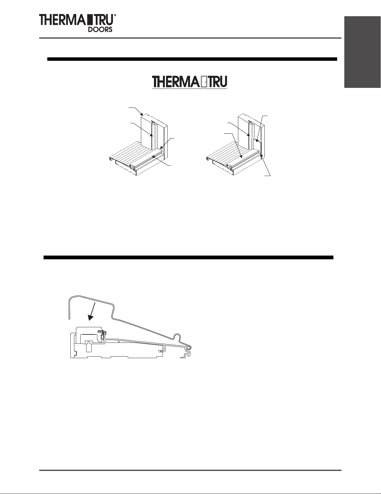
Jamb
Weatherstrip
Sill Instructions
Installation
®
The Mo st P re fe rr ed Bra nd in th e Bu sine ss
Corner Seal Pad Instructions
Basic Fixed Sills
Corner Seal Pad
Weatherstrip
Vinyl Saddle
2. Remove paper backing from corner
seal pad and position pad tight to the
saddle, tucking behind weatherstrip
and in line with edge of jamb. Place
Saddle
1. Place a 1/4” bead of
(Elastomeric and Polyurethane)
sealant at corners where saddle
s
meet side jambs.
Sealant
“hook” over inside edge as shown.
NOTE: Corner seal pads are handed.
Adjustable Sill Cover Instructions
1. Position cover and hook onto sill.
“Hook”
MSCSPSA
NOTE: Be sure to remove sill cover before
any type of floor covering is installed
SITE 1 2014 1.61

Grille Installation Instructions
Installation
Grilles come complete with clips.
4” maximum
from corner
Center
Grille Bar
Locations
FRAMED FLUSH GLAZED
Part # RPWGMC2 Part # RPFGGC
SPRING STEEL CLIPS
FRAMED LITES
Position Clips
Locate clips on vertical sides of frames
4” maximum from each corner and at
center grille bar locations.
CC
Part # RPCGC
4” maximum
from corner
Installation for Lite Frames
Install Clips
Loosen doorlite screws slightly.
Slide flat side of clips under
interior side of doorlite frame.
Retighten screws.
Bend slightly to
tighten fit with
grille if necessary.
Grille Clip
Interior Lite
Frame
Doorlite
Screw
1.62 2014 SITE 1

Grille Installation Instructions
Installation for FC & SS Flush-Glazed Doors
To assure proper installation, carefully remove any excess sealant at glass
edge before installing grille clips.
Insert steel spring clips between stop and glass at the locations shown.
AVOID PUTTING CLIPS IN LINE WITH MUNTINS HORIZONTAL
AND VERTICAL GRILLE BARS. (Note: number of clips may vary from
shown due to grille size and door style.)
Installation
Use the installation tool as shown
to push the clip completely into the
locked position.
Sealant
Section Cut for Clarity
With all the clips installed, insert grille against clips on one
side. Gently push opposite side of grille against glass,
locking all clips into frame. Remember to gently press the
top and bottom of the grille against the glass.
Clips will be hidden when grille is inserted.
To remove, gently pull away from the glass surface at one
long side of the grille where the muntins meet the grille
frame.
SITE 1 2014 1.63

Grille Installation Instructions
Installation
Installation for Flush-Glazed
Classic-Craft
®
Locate grille clips under molding
edges where molding meets glass.
11-7/16”
22-27/32”
21-17/32”
43-3/32”
Notch Locations
Bend slightly to
tighten fit with
grille if necessary.
Insert grille into door, placing one long
side against hardware.
Snap into place along all other sides.
Insert grille clips
by sliding in spade
edge of clip under
molding and press clip
all the way in.
1.64 2014 SITE 1

SDL Bar Installation Instructions
NOTE: TEMPERATURE RANGE FOR OPTIMUM TAPE ADHESION IS 70° TO
When installing over GBG’s only use bronze flat bar patterns
SDL Preparation for Interlocking Bar Patterns:
(Smooth Star / Fiber Classic)
100°F. MINIMUM APPLICATION TEMPERATURE IS 60°F. BOTH THE DOOR AND
LITE DIVIDER ARE TO BE IN THIS TEMPERATURE RANGE. ADHESIVE IS NOT
REPOSITIONABLE.
Materials Needed:
70% Isopropyl Alcohol or adhesion promoting solution
Clean rags
½” Masking tape
J-Roller
Shim stock or business card
Pencil
Plastic zip ties or coffee stirrers
Sanding materials
Use notches to
mark frame
Installation
1. Starting at the external glass side, take a horizontal divider and place
it at the top of the glass. Center the bar in the opening and use the
notch(es) on the divider to mark on the frame the top position of the
vertical divider(s). Slide the bar to the bottom of the glass and repeat
for the bottom position of the vertical dividers.
2. Take a vertical divider and center between the frame markings. Mark
amount of bar to trim (if necessary). There should be 0.015” - 0.020”
clearance (use a business card as a shim) on each side to allow for
expansion or contraction. Repeat for each vertical divider. Be sure to
mark each divider with its location (left/right).
3. Trim bars at appropriate angle (see below) to their correct size. Trimming may be done with a stationary belt
sander, disc sander, or sanding block.
Framed Lites Framed Lites Flush Glazed
(7x64, 21x15, 22x47, 22x64) (8x36, 8x47, 20x64, 22x36) (all sizes)
45°
4. Place a trimmed vertical bar to one side of the glass and use the notches on the dividers to mark on the frame the
position of the horizontal dividers. Repeat on the other side of the glass.
5. Assemble the vertical and horizontal bars together and center the bars on the glass at the frame markings without
removing the carrier backing tape. Mark amount of bar to trim (if necessary). There should be 0.015” - 0.020”
clearance on each side. Repeat for each horizonal divider. Be sure to mark each divider with its location
(top, bottom, center, etc).
35°
67°
6. Disassemble bars. Trim bars at appropriate angle to their correct size.
SITE 1 2014 1.65

Installation
SDL Bar Installation Instructions
(Smooth Star / Fiber Classic)
7. Assemble the horizontal and vertical divider(s). Use masking tape to secure the divider bars together at the joints.
Peel off the Carrier Backing from all of the divider pieces. Clean any trimming residue from tape using
70% Isopropyl Alcohol. Lightly place the tips of small zip ties or coffee stirrers roughtly 1/8” onto the adhesive
backs as shown. For each of the divider bars, position 1 tie at each end of the divider and each joint, and 1-2 ties
in the middle. The ties will keep the adhesive backing off of the glass during final positioning.
Carrier backing
Small Zip Tie
or Coffee Stirrer
Glass Preparation:
Moisten a clean cloth with 70% Isopropyl Alcohol or use an adhesion promoting solution. Wipe the glass before
attaching dividers. Allow to dry.
FAILURE TO PREPARE THE GLASS PROPERLY WILL RESULT IN POOR TAPE ADHESION.
DO NOT USE A GLASS CLEANER TO PERPARE THE GLASS AS THIS WILL PREVENT PROPER ADHESION.
SDL Installation:
1. Position the divider grid back onto the glass using the frame position marks. Check to ensure that, for all of the
frame to divider points, there is a 0.015” - 0.020” gap between the divider and the frame. Once in position, press
down at all of the ends opposite the zip tie to lock the position, and then pull out that zip tie. Once all of the divider
ends are attached, pull out the middle zip ties from the dividers. Using a J-Roller, roll firmly along the entire length
of the horizontal and vertical dividers. Look through the interior side to confirm all dividers adhere to the glass,
particularly around the perimeter and divider joints. Once attached, remove the masking tape.
2. Repeat steps for interior frame side.
1.66 2014 SITE 1

SDL Bar Installation Instructions
SDL Preparation for Non-Interlocking Bar Patterns:
(Smooth Star / Fiber Classic)
1. Make template to the dimensions required for your lite pattern (see subsequent pages).
2. Beginning with the exterior, position each divider using the proper template and mark position on the frame. Center
bar in opening. Mark amount of bar to be trimmed (if necessary). There should be 0.015” - 0.020” clearance
(use a business card as a shim) on each side to allow for expansion or contraction. Repeat for each divider. Be sure to
mark each divider with its location (top, middle, bottom, etc).
3. Trim bars at appropriate angle (see below) to their correct size. Trimming may be done with a stationary belt sander,
disc sander, or sanding block.
Framed Lites Framed Lites Flush Glazed
(7x64, 21x15, 22x47, 22x64) (8x36, 8x47, 20x64, 22x36) (all sizes)
Installation
45°
Glass Preparation:
Moisten a clean cloth with 70% Isopropyl Alcohol or use an adhesion promoting solution. Wipe the glass before
attaching dividers. Allow to dry.
FAILURE TO PREPARE THE GLASS PROPERLY WILL RESULT IN POOR TAPE ADHESION.
DO NOT USE A GLASS CLEANER TO PERPARE THE GLASS AS THIS WILL PREVENT PROPER ADHESION.
SDL Installation:
1. Peel off the Carrier Backing from all of the divider pieces. Clean any trimming residue from tape using
70% Isopropyl Alcohol. Lightly place the tips of small zip ties or coffee stirrers roughly 1/8” onto the adhesive
backs as shown. For each of the divider bars, position 1 tie at each end of the divider and 1-2 ties in the middle.
The ties will keep the adhesive backing off of the glass during final positioning.
Carrier backing
35°
67°
2. Position the dividers back onto the glass using the frame marks. Check that the dividers cover the internal
GBGs (if present). Press down on each end of the divider to lock the position and remove the zip tie. Repeat
for the other end. Remove the remaining zip tie(s). Using a J-Roller, roll firmly along the entire length of the
dividers. Look through the interior side to confirm all dividers adhere to the glass, particularly around the
perimeter.
3. Repeat steps for the interior dividers. Check the alignment of the interior dividers with the exterior dividers
before attaching interior dividers.
SITE 1 2014 1.67
Small Zip Tie
or Coffee Stirrer
Zip Ties

Installation
SDL Bar Installation Instructions
(Smooth Star / Fiber Classic)
21 X 15
2 LITE CRAFTSMAN
TOP
9.480
TOP
6.500
21 X 15
3 LITE CRAFTSMAN
TOP
6.500
5.940
TOP
TOP
1.68 2014 SITE 1

7 x 64
1 - Lite Craftsman
SDL Bar Installation Instructions
(Smooth Star / Fiber Classic)
7 x 64
5 - Lite
8 x 64
5 - Lite
Installation
Lite Frame
5 7/8
END
13 15/16
END
Flush Glaze
5 7/8
END
5 7/8
MID
11 11/16
Lite Frame
5 7/8
END
Same Template
for END and MID
11 3/4
11 11/16
END
MID
Flush Glaze
7
END
11 11/16
7
END
MID
MID
11 3/4
MID
END
MID
END
Lite Frame
6 7/8
END
6 7/8
MID
10 11/16
10 5/8
8 x 47
4 - Lite
END
MID
8 x 36
3 - Lite
Flush Glaze
7.000
END
END
10 15/16
Lite Frame
6 3/4
END
10 7/8
END
END
SITE 1 2014 1.69

Spring Hinge Instructions
Installation
INSTRUCTIONS FOR THERMA-TRU ADJUSTABLE TENSION SPRING HINGE
Installation:
HEX KEY
CROSS PIN
First mount the hinges by matching the hinge leaf (with the Therma-Tru logo) to the door,
then match the other leaf (with the “UL” logo) to the jamb. Doing this may require having
adjustment end down depending on handing.
1. Place door in closed position. Insert allen wrench in hex adjustment hole as shown in
left diagram.
2. If adjustment end is up, turn hex key clockwise to desired spring tension.
If adjustment end is down, turn key counterclockwise to desired spring tension.
Observe caution notes.
3. Insert cross pin when holes in center stud and hinge knuckle line up. Slowly release pressure
on the hex key.
4. Remove hex key and test closing action of door.
5. Repeat steps 1-4, if necessary, to increase spring tension.
To make tension adjustment tamperproof, snip off cross pin at break-away head.
Do not remove head if future adjustment may be needed.
HEX ADJUSTMENT ON TOP
LEFT-HAND APPLICATION
- Use 3-1/2” spring hinge for 1-3/8” thick doors, maximum 2’8” wide X 7’ high.
- Use 4” or 4-1/2” spring hinge for 1-3/4” thick doors, maximum 3’ wide X 7’ high
- Doors over 5’ high require three hinges. At least two of the three must be spring hinges.
- The maximum door size and number of spring hinges required are based on limits set
forth in NFPA 80. For maximum versatility, use all spring hinges.
NOTE:
Adjust spring hinge to minimum tension required to close and latch the door.
Overtensioning will reduce the spring life.
Caution: Do not exceed three holes of tension for doors opening 180 degrees. Do not
exceed four holes of tension for doors opening 90 degrees.
DOOR
JAMB
HEX ADJUSTMENT ON BOTTOM
RIGHT-HAND APPLICATION
1.70 2014 SITE 1

Screen Installation
“Wide Profile” Screen Installation - Hinged Patio
Installation
Adapter Track Latch
Screen
Remove existing screen track.
1
Insert wheels of top hung adapter into top hung track as
2
shown.
Position track up into screen channel. Drill 1/16” pilot holes
3
thru holes in track into head jamb approximately 1/4” deep.
#4 x 1/2”
pan head screw
#10 x 1/2”
pan head screw
#6 x 5/8”
pan head screw
Align adapter with ed
6
Drill 1/8” holes thru hole locations in adapter into screen
7
from interior of unit.
Fasten with #10 x 1/2” screws.
Close screen door and locate position of latch. Mark hole
8
locations for latch. Drill 1/16” pilot holes into side jamb.
Fasten with (2) #6 x 5/8” pan head screws.
ge of screen.
Fasten track to head jamb with #4 x 1/2” flat head screws.
4
Insert screen into adapter channel and rotate down
5
engaging wheels in bottom of screen with track on sill.
1750 Indian Wood Circle Maumee, OH 43537
1-800-THERMATRU (843-7628)
www.thermatru.com
© 200 5 Therma-Tru Corp.
Therma-Tru D oors is an op erating co mpany of Fo rtune Brand s, Inc.
Part # TH SINSTALL
4/1 /05
SITE 1 2014 1.71

Installation
Screen Installation
Adapter Track Latch
“Wide Profile” Screen Installation - Sliding Patio
Align adapter with edge of screen.
6
Doubles/Triples: Align with edge OPPOSITE of handle side.
Quads: Align with edge on handle side.
Screen
Remove existing screen track by rotating the back edge
1
down as you pry it out.
Insert wheels of top hung adapter into top hung track as
2
shown.
Position track up into screen channel. Drill 1/16” pilot holes
3
or punch with an awl, thru holes in track into head jamb
approximately 1/4” deep.
#4 x 1/2”
pan head screw
#10 x 1/2”
pan head screw
#6 x 5/8”
pan head screw
Drill 1/8” holes thru hole locations in adapter into screen
7
from exterior of unit.
Fasten with #10 x 1/2” screws.
Close screen door and locate position of latch on side jamb.
8
Mark hole locations for latch. Drill 1/16” pilot holes.
Fasten with (2) #6 x 5/8” pan head screws.
Fasten t
4
5
rack to head jamb with #4 x 1/2” flat head screws.
Insert screen into adapter channel and rotate down
engaging wheels in bottom of screen with track on sill.
Quad Systems Only
9
Position screen astragal on passive screen so it does not
interfere with head and sill tracks. Pre-drill (4) equally
spaced 1/8” pilot holes. Fasten astragal to screen with
(4) #8 x 1” pan head screws.
Active Passive
#8 x 1” pan head screw
1.72 2014 SITE 1

Screen Installation
French Door Hinged Screen Installation
Installation
French Door Hinged Screen Materials Supplied
Left hinge door
panel side jamb
and bottom
expander
attached
Head Channel
Door Handle Package
Spring Latch (2)
20 - 1” Stainless Steel Screws
4 - 3/4” Stainless Steel Screws
Place head channel at the top of the door opening on the
1
exterior side, centering it between the right and left side
jambs.
Using a 1/8” drill bit, pre-drill a hole in the head brickmould
using the pre-punched holes in the aluminum channel as
a guide.
Fasten head channel to head brickmould
stainless steel screws.
Astragal
Right hinge door
panel side jamb
and bottom
expander
attached
using #8 x 1”
Position the right or left door panel into the frame.
2
Be sure the side hinged channel aligns properly with the
head jamb miter.
Using a 1/8” drill bit, pre-drill a hole into the side
brickmould using the pre-punched hole in the aluminum
channel as a guide.
Fasten side jamb channel to side brickmould using #8 x 1”
stainless steel screws and check for proper alignment
Repeat for remaining door panel.
Trim the black rubber door sweep even with the adjustable
3
bottom expander. Crimp the ends of the slot with pliers
to prevent the sweep from sliding out.
Bott om of Doo r
Crimp H ere
1750 Indian Wood Circle Maumee, OH 43537
1-800-THERMATRU (843-7628)
www.thermatru.com
© 200 5 Therma-Tru Corp.
Therma-Tru D oors is an op erating co mpany of Fo rtune Brand s, Inc.
Part # DD SINSTALL
1/1 /05
Install the handle hardware on the active door .
4
CAUTION: BE SURE TO POSITION THE SCREEN
DOOR HANDLE SO THAT IT DOES NOT INTERFERE
WITH THE OPERATION OF THE HANDLE SET
ON THE PRIMARY DOOR.
At desired height, fold selfadhesive template to door.
Mark center of the three
holes on both sides
Using a 5/16” drill bit,
bore the three holes 1/2
way through on both sides.
Note: Ream out center hole by inserting d
with a slight wobbling action to clear hole and allow
complete freedom of action for spindle.
SPINDLE MUST BE FREE.
rill and rotating
SITE 1 2014 1.73

Installation
Screen Installation
Assemble outside handle with button, spindle and spring.
5
Push this assembly through installation holes from outside
of door as shown.
Depress button to extend spindle. Position latch mechanism
over holes on inside of door, guiding spindle into
rectangular slot in center of mechanism. Insert (2) machine
screws into threaded sleeves and screw each down to
snug position.
French Door Hinged Screen Installation
Install the spring latches to the passive door at the head
7
using the spacer and screws provided. Base of the latch
should be 1/4” down from the head channel.
Close both panels and recheck for proper clearance
8
between astragal and active panel (1/8”). Check for
proper latch engagement. Secure the astragal to the
passive panel by pre-drilling 4 holes with a 1/8” drill
bit and using 4-3/4” screws. Adjust the bottom expander
to the desired position.
Place the astragal on the passive panel (See Inset) allowing
6
an 1/8” gap. Top of astragal should be even with top of
door. Fasten through the center of the slot. Close active
panel and adjust astragal for even gap.
Position the remaining spring latch to expander and
9
the strike plate (lip to the outside) to sill. Once proper
location has been determined so that the door is aligned
with frame, fasten with enclosed screws.
1.74 2014 SITE 1

Screen Installation
Install Screen Door
Installation
Head
Screen
Track
Screen
Sill Track
Install screen door by inserting
top guide wheels on head track.
Lift bottom wheels up and engage
with lower sill track.
SITE 1 2014 1.75

Screen Installation
Venting Sidelite Screen
Materials Supplied
Screen
Side Screen tracks (2)
Install Top Screen Track
1
Remove weatherstrip prior to installation.
From the interior, position top screen track 1/2” back
from the head jamb stop, making sure to center between
the side jamb and the mullion.
Top Screen Track
#6 x 3/4”
PFH Screws
Install Side Screen Tracks
2
Assemble the left and right screen tracks following the
same steps as installing the head screen track,
positioning as shown below.
Make sure to position flush with the top screen track,
and that both sides are completely straight.
Interior
.500 .500
Top View
Install Screen
3
Note: Make sure that all thumb clips are pulled in before
installing the screen.
Interior
.500
Top View
Using a 3/32” drill bit, drill two holes approximately
3/4” deep into the head jamb using the pre-punched holes
in the top screen track as a guide.
Fasten top screen track to head jamb using
two #6 x 3/4” screws.
Starting at the bottom, insert the screen then roll in towards
the top. Gently yet firmly press screen into place.
Push the thumb clips back in until they snap back into
the screen track.
Re-insert weatherstrip.
1.76 2014 SITE 1
 Loading...