

Therma-Stor Products Group XT150H User Manual
INSTALLER’S & OWNER’S MANUAL
HVAC INSTALLER: PLEASE LEAVE MANUAL FOR HOMEOWNER
P/N 4026480 • Serial No.___________________________
Dehumidification
The highly efficient Ultra-Aire XT150H dehumidifier utilizes
refrigeration to cool the incoming air stream below its dew point.
This cooled and drier air is used to pre-cool the incoming air stream
resulting in a significant increase in overall efficiency. After the precooling stage, the processed air is reheated by passing through the
condenser coil. The heat removed by the evaporator coil is returned
to the air stream, resulting in an overall temperature increase of the
air leaving the unit.
The Ultra-Aire XT150H is controlled by 24 volt remote wired controls.
A variety of controls are available suitable to various applications.
P.O. Box 8680 Madison, WI 53708 • TOLL-FREE 1-800-533-7533 • www.thermastor.com • sales@thermastor.com
Fresh Air Ventilation
Optional fresh outdoor air may be ducted to the unit via a six inch
round duct. This provides fresh air to dilute pollutants and maintain
high oxygen content in the air. The amount of fresh air ventilation
can be regulated by a variety of dampers and controls.
Air Filtration
The Ultra-Aire XT150H includes air filtration to improve indoor air
quality. A MERV-11 media filter is standard. An optional external
MERV-14 deep pleated 95% media filter is available for optimum air
filtration and to reduce potentially harmful airborne particles. If the
optional filter is chosen, a standard filter operates as a prefilter.
© 2007 Therma-Stor LLC • Manual P/N TS-372, 8/07

TABLE OF CONTENTS
Table of Contents
Safety Precautions ......................................................................... 3
1. Intended Application ..................................................................4
2. Specifications ...........................................................................4
3. Installation ................................................................................4
3.1 Location .............................................................................4
3.2 Electrical Requirements ...................................................... 4
3.3 Condensate Removal .......................................................... 5
3.4 Ducting ............................................................................... 5
3.4A Installing Duct Collars ................................................. 5
3.4B Ducting for Dehumidification .......................................5
3.4C Ducting for Fresh Air ....................................................6
3.4D Installation in a Basement ..........................................6
3.4E Installation in a attic ....................................................7
3.4F Installation with (2) HVAC systems ............................... 7
3.4G Installation without an HVAC system ............................ 7
3.5 Quiet Installation .................................................................7
3.6 Noise Abatement ................................................................ 7
4. Controls ...................................................................................7
4.1A Humidity/Fan Control Panel WITHOUT Fresh Air
Ventilation or Damper ........................................................8
4.1B Humidity/Fan Control Panel WITH Fresh Air
Ventilation and WITHOUT Damper ......................................8
4.1C Humidity/Fan Control Panel WITH Fresh Air
Ventilation AND Damper .................................................... 8
4.1D Ventilation Timer and Humidity Control
WITH Fresh Air AND Motorized Damper ..............................8
4.1E DEH 3000 Digitial Control
WITH Fresh Air AND Damper ..............................................8
4.1F DEH 3000 Digital Control WITHOUT Fresh Air ...............9
4.2 Humidity Control Adjustment .............................................. 8
4.3 Fan/Filter Switch .................................................................8
4.4 Ventilation Timer .................................................................8
4.4A Setting the Time ..........................................................9
4.4B Ventilation Schedule .................................................... 9
4.4C Automatic or Manual Mode ..........................................9
Controls Wiring Diagram .................................................... 10
5. DEH 3000 Digital Control ........................................................11
5.1. Specifications ...................................................................11
5.2. Installation .......................................................................11
5.2A Install Instructions .....................................................11
5.2B Wiring........................................................................ 11
5.2C Auxillary Relay Operation ........................................... 12
5.2D Dehumidifier Lockout ................................................ 12
5.2E Location .................................................................... 12
5.2F Testing .......................................................................12
5.3. Operation .........................................................................14
5.3A Display ......................................................................14
5.3B Setting ...................................................................... 14
5.3C On/Off Setting ..........................................................14
5.3D Setting Clock Time ...................................................14
5.3E Setting Relative Humidity Setpoint ............................ 14
5.3F Fan Setting & Operation ............................................ 15
5.3G Damper Operation and Setting (Ventilation) ..............15
5.3H Intermittent/Programmed Ventilation ........................ 16
5.3 I Temperature Cutout Programming.............................17
5.3J Default Settings ........................................................ 17
6. Maintenance ........................................................................... 18
6.1 Standard Air Filter ............................................................. 18
6.2 High Efficiency Air Filter ....................................................18
6.3 Impeller Fan Oiling ............................................................ 18
6.4 Fresh Air Return ...............................................................18
7. Service ....................................................................................18
7.1 Warranty ..........................................................................18
7.2 Technical description ........................................................ 18
7.3 Troubleshooting ................................................................18
7.4 Refrigerant Charging .......................................................19
7.5 Impeller Fan Replacement ............................................... 19
7.6 Compressor/Capacitor Replacement .................................20
7.6A Checking Compressor Motor Circuits ........................20
7.6B Replacing Burned Out Compressor ........................... 20
7.6C Replacing Compressor-Nonburn Out......................... 21
7.7 Remote Controls ............................................................... 21
7.7A Humidity Control ........................................................21
7.7B Ventilation Timer ........................................................ 21
7.8 Defrost Thermostat ...........................................................21
7.9 Electric Ventilation Damper ...............................................21
7.10 Condensate Pump Kit .....................................................21
Electrical Schematic ...................................................................22
Pictorial Electrical Diagram .......................................................... 23
Service Parts List ........................................................................24
Optional Parts List ....................................................................... 25
Door and Collar Assembly ...........................................................26
Warranty ......................................................................................27
2
Ultra-Aire XT150H Installer’s & Owner’s Manual

SAFETY PRECAUTIONS
1. Safety Precautions
Read the installation, operation and maintenance instructions
carefully before installing and operating this device. Proper
adherence to these instructions is essential to obtain maximum
benefit from your Ultra-Aire XT150H indoor air quality system.
READ AND SAVE THESE INSTRUCTIONS
• The device is designed to be installed INDOORS IN A SPACE THAT
IS PROTECTED FROM RAIN AND FLOODING.
• Install the unit with space to access the back or side panels
for maintenance and service. DO NOT INSTALL UNIT WITH THE
SERVICE PANELS INACCESSIBLE.
• Avoid directing the discharge air at people, or over the water in
pool areas.
• If used near a pool or spa; be certain there is NO chance the unit
could fall into the water, be splashed and that it is plugged into a
GFI GROUND FAULT INTERRUPT OUTLET.
• DO NOT use the device as a bench or table.
• DO NOT place the device directly on structural members. Provide
vibration isolation in order to minimize operational vibration
and/or noise.
• A drain pan MUST be placed under the unit if installed above a
living area or above an area where water leakage could cause
damage
3
Ultra-Aire XT150H Installer’s & Owner’s Manual

FOR HVAC INSTALLER ONLY
1. Intended Application for Ultra-Aire XT150H
For the ideal installation, draw air from the central part of the home
and return it to isolated areas of the home like the bedrooms, den,
utility room, or family room. The ductwork of the existing heating
system can be used to supply air to the home.
2. Specifications
Model: Ultra-Aire XT150H
Indoor Air Quality System
Electrical: 110-120 VAC, 6.9 Amps, 60 Hz,
grounded
Water Removal Capacity: 150 pints/day @ 80°F, 60% RH
Operating Temp. Range: 56°F min., 100°F max.
Air Flow: 415 CFM @ 0.0" WG
365 @ 0.4" WG
Refrigerant Charge: 2 lb., R-410.A
Duct connections: Round 10" & 6" inlets, 10" outlet
(ovaled)
Filter Size: 2" X 16" X 16"
Size (w/o duct collars): 37" wide X 22" high X 20 5/8" deep
Unit Weight: 134 lbs.
3. Installation
3.1 Location
The Ultra-Aire XT150H can be installed in a variety of locations
to meet the owner's needs as listed below. In all cases keep the
following cautions in mind:
• It is designed to be installed INDOORS IN A SPACE THAT IS
PROTECTED FROM RAIN AND FLOODING.
• Install the unit with space to access the back and side panels for
maintenance and service and also to allow easy access to the filter
cover panel. DO NOT INSTALL UNIT WITH THE FRONT PANEL OR
FILTER COVER PANEL INACCESSIBLE.
• Avoid discharging the air directly at people, or over the water in
pool areas.
• If used near a pool or spa, be certain there is NO chance the unit
could fall into the water or be splashed and that it is plugged into a
GROUND FAULT INTERRUPTER.
• DO NOT use the Ultra-Aire XT150H as a bench or table.
• DO NOT place the Ultra-Aire XT150H directly on structural
members. Provide vibration isolation in order to minimize
operational vibration and/or noise.
• A drain pan MUST be placed under the unit if installed above a
living area or above an area where water leakage could cause
damage.
Place the Ultra-Aire XT150H on supports that raise the base of
the unit above the top of the flanges on the drain pan beneath it.
Raising the Ultra-Aire XT150H will help the unit drain with gravity
flow. Do not place the Ultra-Aire XT150H directly on structural
building members without vibration absorbers or unwanted noise
may result.
The Ultra-Aire XT150H may be suspended with steel hanger straps
(plumbers tape) or a suitable alternative from structural members,
unit must be supported from underneath. Don't hang from sides
or ends. Remember to place a drain pan under the unit if it is
suspended above a finished area or above an area where water
leakage could cause damage.
The Ultra-Aire XT150H should be located near the existing air
handling system to minimize the required ductwork for connecting
the Ultra-Aire XT150H to the existing air handling system. The
controls for the Ultra-Aire XT150H are remote from the unit and
must be located in the space that is to be conditioned. The controls
are low voltage (24 volt) and should be connected to the Ultra-Aire
XT150H with low voltage thermostat cable.
If fresh air ventilation is desired, thought should be given to the
location for the fresh air ducting. A 6" round insulated duct will
have to be installed on the Ultra-Aire XT150H and run to the outside
of the structure to bring in fresh air. Use an 8" insulated round duct
for lengths of more than 50 feet or if more than 100 CFM is needed.
Consult local codes for necessary distances from exhaust ports
when installing fresh air return.
3.2 Electrical Requirements
WARNING: DO NOT ALLOW THE YELLOW LEAD FROM THE
ULTRA-AIRE TO CONTACT THE RED LEAD OR WHITE LEAD FROM
THE ULTRA-AIRE OR DAMAGE TO THE TRANSFORMER WILL
RESULT.
The Ultra-Aire XT150H plugs into a common grounded outlet. It
draws around 6.9 Amps under normal operating conditions. If used
in a wet area (pool, spa room, or basement prone to flooding), a
ground fault interrupter protected circuit is required.
Install the remote control panel in a central area of the structure
where it will sense the relative humidity of the structure accurately.
Do not install the control panel where it may not accurately sense
the relative humidity such as near HVAC supply registers, near
exterior doors, or near a pool or spa. The installer must supply the
wiring between the Ultra-Aire XT150H and the control panel. Be
sure to safely route the control wiring to prevent damage during
installation. Be careful not to cross the wires when connecting the
Ultra-Aire XT150H and the remote control panel or damage to the
transformer may result.
4
Ultra-Aire XT150H Installer’s & Owner’s Manual
FOR HVAC INSTALLER ONLY
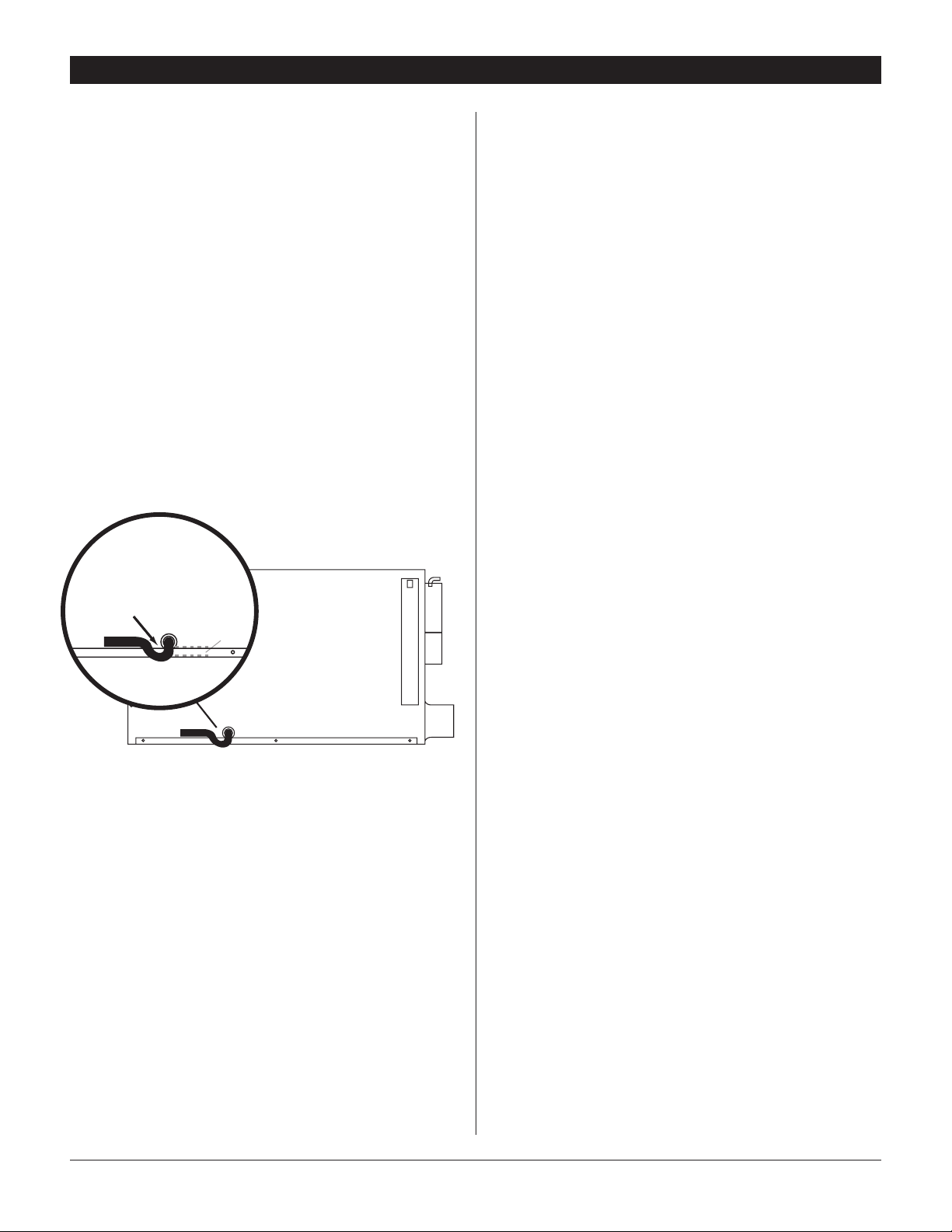
1.00"
External drain trap on unit
is recommended
The remote controls of the Ultra-Aire XT150H are powered by a low
voltage circuit (24 Vac) and must NEVER contact or be connected
to a high voltage circuit. The control wires leaving the Ultra-Aire
XT150H and the remote control panels are numbered and colorcoded to prevent confusion. Some of the control wires leaving the
Ultra-Aire XT150H may not be used with certain control panels and
should be left safely disconnected with wire nuts taped onto the
stripped ends. Be sure to consult the electrical schematic in this
manual or inside the access panel of the Ultra-Aire XT150H before
making the control connections.
3.3 Condensate Water Removal
Condensate drains by gravity via the drain port. Use 3/4" male NPT
PVC pipe. Route drain pipe to drain. Install a trap if possible. Take
care when installing drain pipe to drain port. Use an adjustable
wrench to secure the drain port. An optional condensate pump kit
may be installed if a lift is required to dispose of the condensate.
The condensate pump kit can be ordered directly from the factory.
See the optional parts list for information on the kit.
may draw air from a basement that is open to the home. All flexible
ducting connected to the Ultra-Aire XT150H should be UL listed.
The inlet of the Ultra-Aire XT150H is the 10" diameter hole in the
filter enclosure of the unit. A 10" round collar is supplied with the
unit to attach to round duct. The duct may be permanently attached
to the collar. A 6" round collar is provided with the unit to attach to
the 6" hole in the filter enclosure. The 6" collar should be capped
if fresh make-up air is not desired. If fresh make-up air is desired,
see Section 3.4C.
A 10" round (ovaled) collar is supplied with the unit for the outlet of
the Ultra-Aire XT150H.
A length of flexible ducting on all Ultra-Aire XT150H duct
connections is recommended to reduce noise and vibration
transmitted to rigid ductwork in the structure.
Ducting the Ultra-Aire XT150H as mentioned in Sections 3.4A-3.4G
requires consideration of the following points:
Duct Sizing: For total duct lengths up to 25', use a minimum 10"
diameter round or equivalent rectangular. For longer lengths, use a
minimum 12" diameter or equivalent. Grills or diffusers on the duct
ends must not excessively restrict airflow.
3.4 Ducting
3.4A Installing Duct Collars
The Ultra-Aire XT150H is equipped with 10" and 6" round inlet
collars and a 10" round (ovaled) exhaust collar. Follow instructions
included with collars.
3.4B Ducting for Dehumidification
For the ideal installation, draw air from the central part of the
home and return it to the isolated areas of the home like the
bedrooms, den, utility room, or family room. The ductwork of the
existing heating system can be used to supply air to the home. If
the existing supply goes to isolated areas of the home, discharge
the supply of the Ultra-Aire XT150H into the supply of the existing
heating system. If the existing heating system incorporates a
central supply, installation of a separate supply duct from the UltraAire XT150H to each isolated area is recommended. DO NOT draw
air directly from the kitchen, laundry, or isolated basement. You
Isolated Areas: Effective dehumidification may require that ducting
be branched to isolated, stagnant areas. Use 8" or larger diameter
branch ducting to each of two or three areas, use 6" or larger to
each of four or more areas.
Connecting to existing HVAC systems: An optional 10" check
damper is available from the factory to prevent reverse flow
through the Ultra-Aire XT150H. If the Ultra-Aire XT150H is ducted
to the supply ducting air handler, it is recommended that the check
damper be placed in the Ultra-Aire XT150H supply duct. Contact
the factory when connecting to a static pressure of greater than or
equal to +.5" WG.
5
Ultra-Aire XT150H Installer’s & Owner’s Manual
FOR HVAC INSTALLER ONLY
3.4C Ducting for Fresh Air
Fresh air can be brought into the structure by connecting an
insulated duct from outside to the 6" Ultra-Aire XT150H inlet and
by turning on the fan switch or activating the humidity control (on
units with the humidity control panel). Activate the ventilation timer
on units with the ventilating and humidity control panel to bring in
fresh air. Refer to Section 4.5 for programming instructions for the
ventilation timer. Advantages of this form of ventilation include:
1. Outside air is filtered before entering the building.
2. Outside air will be dehumidified before entering if the UltraAire XT150H is running in dehumidification mode.
3. Drawing air from outside and blowing inside aids in slightly
pressurizing the structure. This helps prevent dirty and humid
air from entering elsewhere. It also reduces the potential for
carcinogenic radon gas to enter and provides make-up air for
open combustion and exhaust devices like the clothes drier,
fireplace, and water heater.
4. Adequate exhaust fans are recommended in the bath rooms
and kitchen.
In cold climates or areas where the outdoor dew point is low
at times, ventilation can be used to dehumidify the structure.
This is accomplished by bringing the dry, low dew point air into
the structure during these times. This approach is often more
economical than running the dehumidifier to remove excess
moisture from the structure. In cold climates, it is critical to
adequately ventilate to reduce the inside moisture content to
avoid moisture accumulating in the wall cavities. For example; in a
house that experiences condensation on the interior surface of the
windows during the winter, increasing the amount of ventilation will
often cure the problem.
An insulated 6" diameter duct is generally sufficient to provide up
to 125 CFM of outside air. Large quantities of outside air will either
positively or negatively impact the performance of the Ultra-Aire
XT150H, depending upon inside and outside air conditions. Consult
the factory by calling 1-800-533-7533 for recommendations
regarding the use of higher flows with your specific application.
The outside air duct should be connected to the 6" round collar
on the filter enclosure of the unit. The 6" round collar includes a
manual damper. Adjust the manual damper to provide the desired
amount of fresh air for ventilation. The amount of fresh air should
be based on the size and occupancy of the residence. If you are
unsure of your ventilation air requirements, consult the factory by
calling 1-800-533-7533 for assistance.
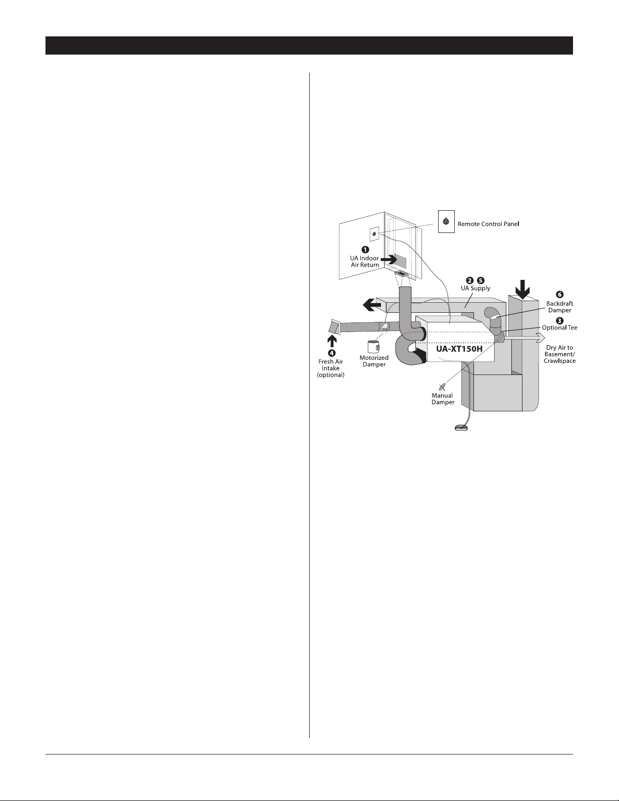
3.4D Installation in a Basement or Crawlspace
with an Existing Forced Air HVAC System
It is recommended that a new, separate return duct be installed for
the Ultra-Aire XT150H from a central area of the house. If this is not
possible, and if the existing system has multiple returns, select one
to disconnect from the existing forced air system and use it for the
dedicated Ultra-Aire XT150H return. Always select a return from a
central location in the structure in an area that is always open to
the rest of the structure. Do not use a return from a room that may
have its door closed much of the time.
If the structure in which the Ultra-Aire XT150H is to be installed has
an existing forced air HVAC system, utilize the HVAC system to make
the Ultra-Aire XT150H installation easier.
Basement Installation: Install a separate 10" return for the UltraAire XT150H in a central area of the structure. Duct the supply of the
Ultra-Aire XT150H to an optional 10" x 10" x 10" tee/damper that
is 20% open to the basement. This allows the ability to discharge a
variable amount of dehumidified air into a basement that may not
be well served by the existing duct system. Duct the other side of
the tee to the air supply of the existing HVAC system. A backdraft
damper is required in the duct between the 10" tee and the central
supply duct to prevent air from being discharged into the basement
during central fan operation. Connect a duct from outside to the
6" collar of the Ultra-Aire XT150H if you wish to provide fresh air
ventilation.
Crawl Space Installation: Install a separate return for the UltraAire XT150H in a central area of the structure. Duct the supply of
the Ultra-Aire XT150H to a 10" x 10" x 10" tee/damper that is 20%
open to the crawl space if desired. Duct the other side of the tee
to the air supply of the existing HVAC system ventilation. Connect
an insulated duct from outside to the 6" collar of the Ultra-Aire
XT150H if you wish to provide optional fresh air.
6
Ultra-Aire XT150H Installer’s & Owner’s Manual
FOR HVAC INSTALLER ONLY
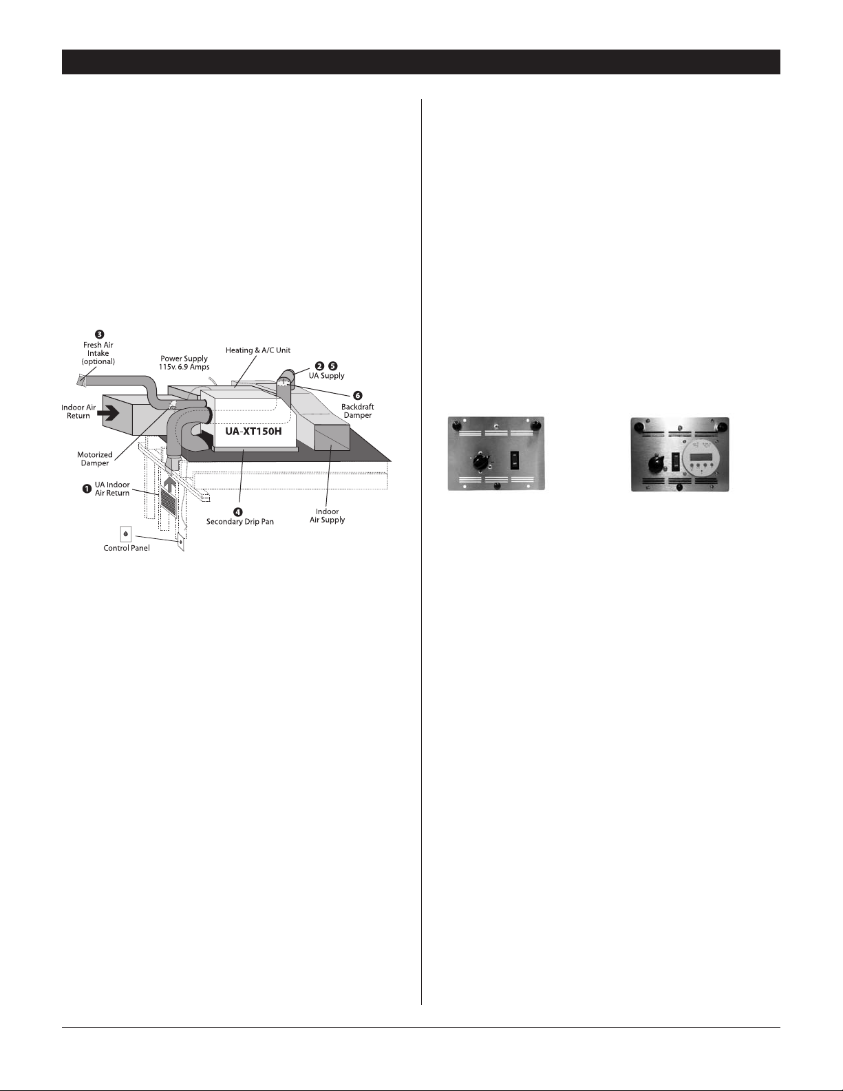
3.4E Installation in an Attic with an
Existing Forced Air HVAC System
ALWAYS install a catch pan with a drain and/or float interrupt
switch for condensate under the Ultra-Aire XT150H in an attic to
reduce liklihood of water damage.
Locate a separate return for the Ultra-Aire XT150H in a central
area of the structure. Duct the supply of the Ultra-Aire XT150H to
the air supply of the existing HVAC system. Connect an insulated
duct from outside to the 6" collar of the Ultra-Aire XT150H if you
wish to provide fresh air ventilation. Adjust damper in the collar
to provide the desired amount of fresh air. Using a remote control,
program the unit to bring in the desired amount of fresh air.
from outside to the 6" collar of the Ultra-Aire XT150H if you wish to
provide fresh air ventilation.
3.5 Quiet Installation
Consider compression vibration and airflow noise during
installation. Use of flex duct and/or vibration isolation materials
during mounting and ducting will result in quieter operation.
3.6 Noise Abatement
A length of flexible ducting on all Ultra-Aire XT150H duct
connections is recommended to reduce noise and vibration
transmitted to rigid ductwork in the structure.
4. Controls
All control panels should be mounted in a central area of the
structure where it can accurately sense the humidity of the air in
the living space and be accessed. All controls require field wiring
from the unit location to the panel mount location.
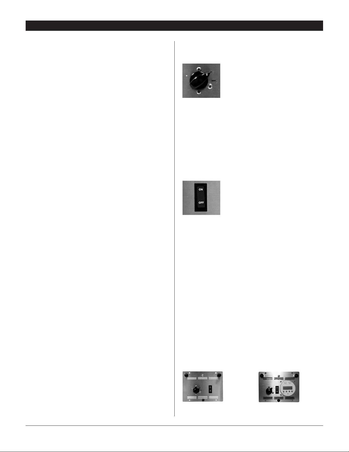
Figure 1:
Humidity/Fan Control Panel
Part No. 4024155
Figure 2: Ventilation Timer
and Humidity Control Panel
Part No. 4024125
3.4F Installation in a Structure with
Two Forced Air HVAC Systems
The Ultra-Aire XT150H can be installed into two typical HVAC
ducting systems. Install a separate return for the Ultra-Aire XT150H
as directed above. Discharge air from the dehumidifier should be
split and routed to each supply ducting system. A balancing damper
and a backdraft damper is required in each duct between the UltraAire XT150H and the HVAC ducting system. This allows airflow to
be adjusted and prevents flow of air between the ducting systems.
Contact the factory for assistance, if necessary.
3.4G Installation in a Structure with No Existing
Forced Air HVAC System
When installing the Ultra-Aire XT150H in a structure that does not
have a forced air HVAC system, a single return for the Ultra-Aire
XT150H should be installed in central open area of the structure.
DO NOT locate the return in a bathroom or a kitchen. The supply of
the Ultra-Aire XT150H should be located in the remote areas of the
structure (such as bedrooms, den, etc.). By ducting this way, the air
inside the structure will circulate through the Ultra-Aire XT150H to
be filtered and dehumidified. Avoid discharging all the air from the
dehumidifier in one location to prevent heat build up in that area. 4"
diameter duct is recommended for branches to the bedrooms, 6"
diameter duct is recommended for branches to larger areas. Refer
to section 3.4B for branch duct sizing. Connect an insulated duct
To determine how each control operates the Ultra-Aire XT150H,
it must first be determined which control is being used and
whether or not the Ultra-Aire XT150H is ducted for fresh air
ventilation. Refer to appropriate section.
Humidity/Fan Control Panel (P/N 4024155) (Figure 1, p.7)
4.1A Humidity/Fan Control Panel WITHOUT Fresh Air
Ventilation or Damper
4.1B Humidity/Fan Control Panel WITH Fresh Air
Ventilation and WITHOUT Damper
4.1C Humidity/Fan Control Panel WITH Fresh Air
Ventilation AND Damper
7
Ultra-Aire XT150H Installer’s & Owner’s Manual
FOR HVAC INSTALLER ONLY
Ventilation Timer/Humidity Control Panel (P/N 4024125)
(Figure 2, p.7)
4.6D Ventilation Timer and Humidity Control WITH Fresh Air
AND Motorized Damper
DEH 3000 Digital Control (P/N 4024539) (Figure 1, p.10)
4.6E Digital Controller WITH Fresh Air AND Damper
4.6F Digital Controller WITHOUT Fresh Air
4.1A Humidity/Fan Control Panel WITHOUT Fresh Air
Ventilation or Damper
The humidity/fan control panel automatically controls the humidity
of the living space. The humidity/fan control panel contains an
adjustable humidity control and a fan switch. The panel has a
cover that must remain open to the air within the living space for
accurate humidity sensing. When the fan switch is in the “ON”
position, air will be continually filtered and circulated throughout
the home. For humidity control operation refer to section 4.2.
4.1B Humidity/Fan Control Panel WITH Fresh Air
Ventilation and WITHOUT Damper
The humidity/fan control panel automatically controls the humidity
of the living space. The humidity/fan control panel contains an
adjustable humidity control and a fan switch. The panel has a
cover that must remain open to the air within the living space for
accurate humidity sensing. Outside air is continually introduced
whenever fan is “ON.” Manual operation of fan filter switch controls
outside air ventilation. Since the fan operates whenever the UltraAire XT150H is dehumidifying outside air will also be introduced.
For humidity control operation refer to section 4.2.
4.1C Humidity/Fan Control Panel WITH Fresh Air
Ventilation AND Damper
In this configuration, a motorized damper has been installed in the
fresh air duct. When the fan/filter switch is in the “OFF” position,
the damper is closed. The Ultra-Aire XT150H will then circulate and
dehumidify air to provide humidity control.
When the fan/filter switch is in the “ON” position, the motorized
damper will open and the fan will run, introducing outside air. The
unit may or may not be dehumidifying in the ventilation mode,
depending on the humidity control setting. See Section 4.2 for
humidity control operation.
4.1D Ventilation Timer and Humidity Control WITH
Fresh Air AND Motorized Damper
Refer to sections 4.7 through 4.9C.
4.2 Humidity Control Adjustment
Set the humidity control to the desired humidity level for the home.
Turning the knob clockwise results in a drier setting. See the back
of the control panel cover for set points.
The dehumidifier will run continuously until
the relative humidity (RH) is reduced to the
humidity control dial setting. Setting the
humidity control to lower RH levels will NOT
Figure 3:
Humidity Control
Adjustment Knob
refrigerant-based dehumidifiers in general) will reduce a warm
space’s RH to a lower level than that of a cool space. Therefore
there is no benefit to set the humidity control to excessively
low levels in cool rooms; doing so will result in long periods of
ineffective dehumidifier run time. Settings below 45% are not
recommended.
increase the dehumidification rate; the unit
will simply run longer to reduce the RH to
the setting. The Ultra-Aire XT150H unit (and
4.3 Fan/Filter Switch
Turning ON the fan/filter switch will
cause the Ultra-Aire XT150H fan to run
continuously, whether the Ultra-Aire XT150H
is dehumidifying or not. This function is
desirable if the unit is used for air circulation
Figure 4
Fan/Filter Switch
constantly filtered through the Ultra-Aire XT150H and circulated
throughout the house. When the switch is OFF the fan will operate
only when the humidity control calls for dehumidification or when
the ventilation timer calls for ventilation.
and filtration to achieve maximum indoor air
quality. When the switch is ON; air will be
4.4 Ventilation Timer
The ventilation timer controls the fan and the motorized fresh
air damper. When the ventilation timer is activated, the UltraAire XT150H will circulate the indoor air, and bring in fresh air
from outside. The ventilation timer should be set for the required
ventilation of the residence. The home should be ventilated with
fresh air as suggested by applicable codes and standards or as
required by the homeowner. The ventilation timer is an electronic
timer that displays the current time. This timer has battery backup,
so it will not require resetting after a power outage. Following
a prolonged power outage the display of the timer will flash on
and off indicating a power outage has occurred. The one-minute
time increments of the ventilation timer allow you to program the
ventilation of your home to fit your schedule.
4.1E DEH 3000 Digital Control WITH Fresh Air AND
Damper
Refer to Section 5.
4.1F DEH 3000 Digital Control WITHOUT Fresh Air
Refer to Section 5.
Humidity/Fan Control Panel
P/N 4024155
8
Ventilation Timer & Humidity
Control Panel • P/N 4024125
Ultra-Aire XT150H Installer’s & Owner’s Manual

FOR HVAC INSTALLER ONLY
The ventilation timer allows six programs with each program
having one “ON” and one “OFF” event. A program allows the
user to turn the ventilation on at a certain day and time, then it
allows them to turn the ventilation off at a certain day and time.
Each of these programs can be repeated daily or weekly or
during a specified block of days. All six of the programs operate
independently of each other. If the timer fails to operate or operates
erratically, check that the control panel receives 24Vac from the
Ultra-Aire XT150H. If 24Vac is present at the control panel, reset
the timer by pressing the reset button at the bottom center of the
timer face. The reset button is the small recessed button with an R
beneath it located below the 1-7 and h buttons. Depress the reset
button until the display clears. Release the reset button. The display
will reappear as 00:00. Resetting the timer will clear the time and
all program settings. After resetting the timer follow the instructions
below to set the correct time and ventilation programs.
4.4A Setting the Time
Set the correct time on the timer by sliding the switch in the upper
right hand corner of the timer to the clock symbol. and pressing the
1-7 (DAY), h (HOUR), and m (MINUTE) buttons. Remember this timer
operates on a 24-hour (military time) clock.
4.4B Ventilation Schedule
Slide the switch in the upper right hand corner to the program
symbol P. “ON” will appear to the right of the time and the number
“1” will appear in the lower right hand corner of the display. The
“1” and “ON” signify the turn on time for the first program. Press
the 1-7, h and m button to choose the days of the week for this
program. You can choose Mon.-Sun., Mon.-Fri., Sat.-Sun., or any
single day of the week. The days chosen are shown along the top
of the display on the ventilation timer. Next press the h button to
set the hour for the start of the ventilation period. Remember this
timer operates on a 24-hour clock (military time). Then press the m
button to set the minutes past the hour to start the ventilation.
4.4C Automatic or Manual Mode
The slide switch in the upper left of the timer is used to choose
between automatic and manual operation. When the slide switch
is set to AUTO mode, the Ultra-Aire XT150H will ventilate when
the scheduled programs call for ventilation. When the slide switch
is set to manual (set to hand symbol on the right), the operation
of the timer is controlled by the I/O button only. Pressing the I/O
button will switch the ventilation timer between ON (detent) and
OFF (detent). As you press the I/O button, “ON” or “OFF” will be
displayed to the right of the time. The “ON” or “OFF” indicates if the
ventilation timer is on or off. The I/O button will manually override
scheduled programs if the timer is in AUTO mode.
Now, with the ventilation start time set; press the I/O button. The
word “OFF” should appear to the right of the time and the number
“1” should remain in the lower right hand corner of the display. The
“1” and “OFF” signify the turn off time for the first program. Set
the turn off time using the 1-7, h and m buttons in the same way
as described above and continue on to the second through sixth
programs. When setting the ventilation programs, you can return
to the current time display by sliding the switch in the upper right
corner of the timer to RUN. The slide switch must be set to RUN for
the timer to operate its scheduled programs.
9
Ultra-Aire XT150H Installer’s & Owner’s Manual
 Loading...