

Therma-Stor Products Group PHOENIX 300 User Manual

PHOENIX 300 Operation & Service Instructions
Therma-Stor Products
A Division of DEC International
Box 8050 Madison, WI 53708
Toll Free 1-800-533-7533
Local 1-608-222-5301
Table of Contents
Specifications
1.
Operation
2.
2.1 Transporting the Phoenix 300 ......................1
2.2 Location ........................................................ 1
2.3 Electrical Requirements ............................... 2
2.4 Condensate Removal ................................... 2
2.5 Ducting .........................................................2
2.6 Power Switch................................................ 2
2.7 Pump Purge Switch ...................................... 2
2.8 Pump Fail Light............................................. 2
2.9 Hour Meter.................................................... 2
2.10 Defrost Control Adjustment ......................... 2
2.11 Low Pressure Control .................................. 3
Maintenance
3.
3.1 Air Filter ........................................................ 3
3.2 Blower Oiling ................................................ 3
3.3 Storage ......................................................... 3
Service
4.
4.1 Warranty ....................................................... 4
4.2 Technical description.................................... 4
4.3 Troubleshooting............................................ 4
4.4 Refrigerant Charging .................................... 5
4.5 Blower Replacement ....................................5
4.6 Compressor/Capacitor Replacement ........... 5
4.6A Checking Compressor Motor Circuits .....5
4.6B Replacing a Burned Out Compressor .....6
4.6C
4.7 Defrost Thermostat & Timer ......................... 7
4.8 Condensate Pump........................................ 7
4.9 Relay.............................................................7
4.10 Time Delay ..................................................7
Wiring Diagram
5.
Service Parts List
6.
.............................................................. 4
Replacing a Compressor- Non-Burn Out
................................................... 1
.......................................................... 1
..................................................... 3
................................................. 8
............................................. 9
... 7
Read the operation and maintenance instructions
carefully
these instructions is essential to obtain maximum
benefit from your Phoenix 300 dehumidifier.
before
using this unit. Proper adherence to
1 Specifications
Model: PHOENIX 300 Dehumidifier
Electrical: 110-120 Vac, 12 Amps, grounded
Capacity: 176 pints per day @ 80°F, 60% RH
Operating Temp. Range: 33°F min., 105°F max.
Air Flow: 540 CFM without external ducting
Refrigerant Charge: 2 lbs., 5 oz. R-22
Optional Duct connection: 10" round outlet
Size: 45" high x 24" wide x 20" deep cabinet
46" high x 29" wide x 25" deep overall
Weight: 175 lbs.
2 Operation
2.1 Transporting the Phoenix
The Phoenix 300 must always be upright when
transported by vehicle. It may be tipped on to its handle
and back for loading and moving by hand.
2.2 Location
Note the following precautions when locating the
Phoenix 300:
•
It is designed to be used
•
If used in a wet area, plug it into a
INTERRUPTER.
DO NOT
••••
•
It must always be used in the upright position.
•
The air inlet on top & the side outlet must be at least
1 foot from walls and other obstructions to air flow.
•
If the humid area is very large, dehumidification can
be improved by adding an outlet duct to circulate air
to stagnant areas (see Sec. 2.5).
use the Phoenix 300 as a bench or table.
INDOORS ONLY
GROUND FAULT
.
Serial No. ________________________________
Purchase Date ____________________________
Dealer's Name ____________________________
Lit. No. TS-218B-0499

2.3 Electrical Requirements
2.8 Pump Fail Light
The Phoenix 300 can be plugged into a grounded 15
Amp circuit. At 80°F, 60% RH, it draws 11.4 Amps. Due
to the high percentage of a 15 Amp circuit’s capacity
that the unit uses, the circuit should be dedicated to
running it only. Amp draw decreases at lower loads and
increases at higher loads. At extremely high loads, a 20
Amp circuit may be required.
The unit briefly draws more amps to start if it has been
stored in a cold area. This may cause a 15 Amp circuit
breaker to trip. A 20 Amp circuit is recommended in
such situations. Some models have a time delay to
delay the compressor start about 2 minutes after the
power switch is turned on. This reduces the unit’s
starting amp draw by starting the blower and
compressor at different times.
If an extension cord is required, it must have a
minimum of 12 gauge conductors if 25 feet long or less
and 10 gauge conductors if greater than 25 feet long.
2.4 Condensate Removal
The Phoenix 300 is equipped with an internal
condensate pump to remove the water that is
condensed during dehumidification. This allows the
condensate to be pumped 30' with the attached hose. If
the condensate must be pumped more than 20 feet
above the unit, a second pump must be added to relay
the condensate.
2.5 Ducting
If the condensate pump fails, water draining into the
pump reservoir will fill above its normal level. A safety
float switch will then turn on the pump fail light (located
next to the pump purge switch) and stop the
compressor. This prevents water from overflowing and
wetting the floor. The safety switch will not allow the
compressor to restart until water has been removed
from the pump reservoir.
2.9 Hour Meter
The digital hour meter measures the cumulative time
that the unit is turned on to tenths of an hour. It stores
its total when the unit is unplugged; the previous total
will be displayed when the unit is next turned on. It
resets to zero after 99,999.9 hours of operation.
2.10 Defrost Control Adjustment
When the Phoenix 300 is used in a cool area, frost will
form on the cooling coil as it dehumidifies. When
enough frost forms, the defrost thermostat will initiate
the timed defrost cycle. The cycle periodically turns off
the compressor while allowing the blower to run. The
frost is melted by the air that the blower draws through
the cooling coil.
The defrost cycle is automatic and designed for
optimum performance above 50°F. If the unit is used in
an area that is below 50°F for more than 2 hours,
adjustment of the defrost timer is recommended to
improve performance (see Sec. 2.10).
A detachable 10" round exhaust collar is supplied that
will allow a 10” round flexible duct to be attached to the
Phoenix 300 outlet. The duct and collar may be quickly
attached to the Phoenix 300 by sliding the 4 collar tabs
into the slots around the blower outlet and rotating the
collar clockwise. It may be quickly removed to transport
the unit more easily.
2.6 Power Switch
The power switch (on left side of hour meter) lights up
when the unit is turned on. The unit will continue to run
in all conditions until the switch is turned off; there is no
dehumidistat.
2.7 Pump Purge Switch
This switch (on right side of hour meter) minimizes the
water left in the condensate pump reservoir for moving
or storage. Pressing and holding the pump purge
switch will cause the condensate pump to run. Hold the
switch in until the flow from the condensate hose stops.
DRYING TIP: Air’s ability to absorb moisture from wet
surroundings and the Phoenix 300’s ability to remove
moisture from that air is greatly improved at higher
temperatures. We recommend that the area to be dried
be heated to over 70°F if possible. Less drying time will
be required and efficiency will improve.
To adjust the defrost timer:
1. Unplug the unit.
2. Remove the front cover (6 screws).
3. The timer is fastened to the right inside panel.
Every fourth peg around the dial is pushed out
from the dial center except one section with 5
pegs out in a row. See figure 1. Each fourth “out”
peg represents 15 minutes of compressor "off"
time during every hour that the unit is in the
defrost cycle.
4. To improve performance below 50°F, the
compressor "off" time must be increased to 30
minutes per hour to allow the frost to completely
melt. To do this, push the pegs out from the dial
2
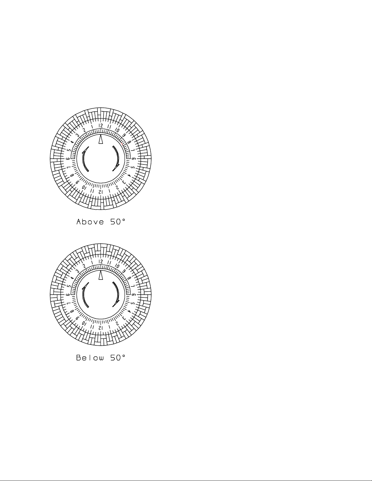
center so that the pegs alternate with 2 toward the
center, then 2 out from the center, all the way
around the dial except for the section now with 6
pegs out in a row (see Fig. 1).
5. Replace the cover.
Change the timer pegs back to the original pattern for
use above 50°F.
2.10 Low Pressure Control
If the low side refrigerant pressure drops to 15 PSIG,
the low pressure control opens and shuts off the
compressor and blower. It is an automatically reset
control. Its primary function is to prevent damage to the
compressor if a leak develops in the refrigeration
system. It may also open if the unit is A) used in a cool
area (below 50°F) and the defrost timer is not adjusted
(see Sec. 2.10) or B) stored where it is below 40°F and
then started. Under these conditions, the unit will
restart within several minutes. Until the unit warms up,
it may cycle several times.
Figure 1: Defrost Control Timer
3
 Loading...