

Page 1
Installation Operation Manual
thermasol.com/solutions
MicroTouch Control
OVER 60 YEARS OF STEAM SHOWER INNOVATION
Page 2
MicroTouch Control and Steamhead Installation Instructions
1 Important Information before You Install
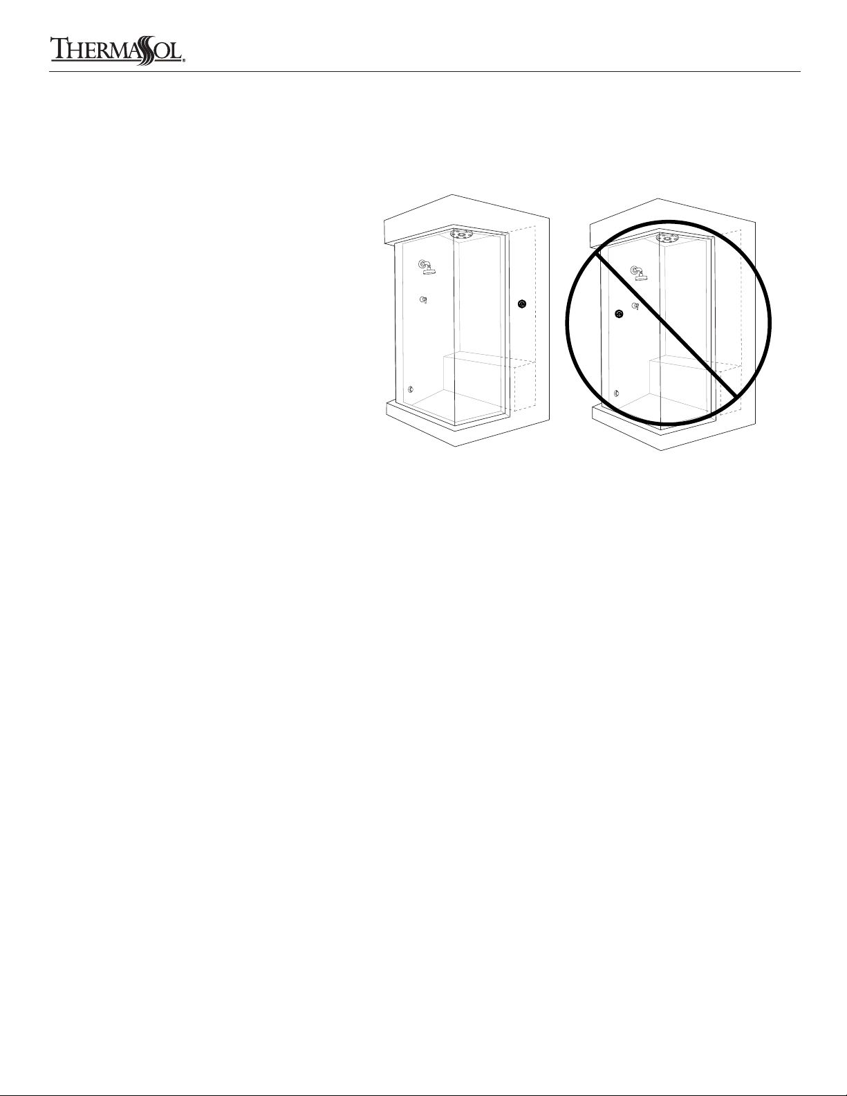
The MicroTouch Control must be installed inside
the shower. The MicroTouch control will only
function on the current TFX, SSA and PRO Series generators.
The control should be installed 60" from the oor of
the shower and away from the steamhead.
The steamhead should be installed 24" from the oor
and 6" from any wall. Locate as far as possible from
the bathing seating area or location of the users and
not below any xtures.
PLEASE REVIEW WARNINGS BELOW AND LEAVE THIS MANUAL WITH HOMEOWNER
DO NOT USE THIS PRODUCT UNLESS YOU HAVE CONSULTED WITH YOUR DOCTOR AND RECEIVED WRITTEN PERMISSION TO DO SO. USE OF
THIS PRODUCT MAY BE HAZARDOUS TO YOUR HEALTH.
PLEASE CONSULT YOUR PHYSICIAN BEFORE USING. IF YOU ARE PREGNANT, ELDERLY, HAVE HIGH BLOOD PRESSURE, DIABETES, SUFFERING
FROM HEART DISEASE, ARE INTOXICATED, OR NOT IN GOOD HEALTH, DO NOT USE THIS STEAM BATH.
STEAM IS HOT! DO NOT TOUCH OR GO NEAR THE STEAMHEAD FROM THE TIME THE UNIT IS “ON,” UP TO ONE HOUR AFTER IT HAS SHUT OFF.
SEVERE BURNS WILL OCCUR IF YOU COME IN CONTACT WITH THE STEAMHEAD OR STEAM EMITTING FROM THE STEAMHEAD.
NEVER ATTEMPT TO FILL AROMA RESERVOIR ON THE STEAMHEAD WHEN UNIT IS IN THE "ON" POSITION. SEVERE BURNS WILL OCCUR.
DO NOT USE THERMASOL AROMATHERAPY OILS, SKIN CARE PRODUCTS OR ANY PRODUCT ASSOCIATED WITH YOUR THERMASOL UNIT
WITHOUT CONSULTING WITH YOUR ALLERGIST OR DOCTOR BEFORE USE. THESE PRODUCTS MAY BE HAZARDOUS TO YOUR HEALTH.
DO NOT USE STEAM ROOM WHILE UNDER THE INFLUENCE OF ALCOHOL OR DRUGS, AS THIS CAN BE HAZARDOUS TO YOUR HEALTH.
YOUR SHOWER MAY BE A SLIP-AND-FALL HAZARD. CHECK WITH YOUR CONTRACTOR OR FLOORING MANUFACTURER REGARDING THE SAFE
USE OF YOUR FLOORING IN A STEAM APPLICATION. SLIPPING AND FALLING INTO THE STEAMHEAD ITSELF OR INTO THE STREAM OF STEAM
EMITTING FROM THE STEAMHEAD WILL CAUSE SERIOUS BURNS OR PHYSICAL INJURY.
IF YOU ARE FEELING UNCOMFORTABLE, DIZZY, FAINT, OR STARTING TO FALL ASLEEP, IMMEDIATELY EXIT THE STEAM ROOM.
DO NOT USE STEAM ROOM IF YOU ARE UNDER THE AGE OF 16 UNLESS SUPERVISED BY AN ADULT.
THERMASOL STEAM BATH GENERATORS ARE NOT DESIGNED TO BE USED FOR SPACE HEATING PURPOSES.
THERMASOL STEAM BATH GENERATORS ARE FOR INDOOR USE ONLY. THEY SHOULD NEVER BE LOCATED OUTSIDE THE HOME.
All products must be installed in accordance with installation instructions provided. Failure to do so may invalidate warranty at manufacturer’s discretion.
©2014 ThermaSol.
Read warnings on page 2. For illustrative purposes only. Consult with qualied professional for steam room construction details.
2
THERMASOL.COM I 800.776.0711
Page 3
MicroTouch Control and Steamhead Installation Instructions
2 Tools and Materials
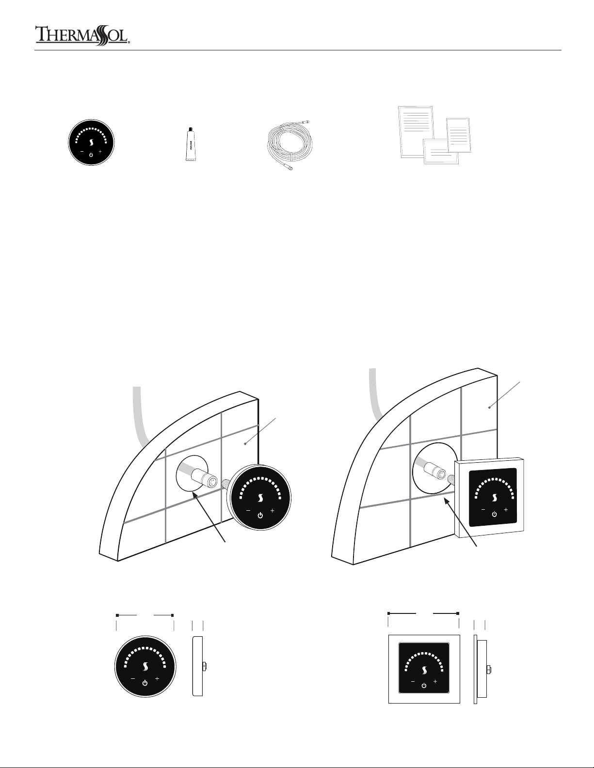
Controller
(Round style shown here)
Materials needed:
o MicroTouch control
o CAN bus cable
o Silicone
o Other materials as required
Silicone 50-foot control data cable (included
Tools needed:
o Pipe wrench
o Tubing cutter
o Wire cutters or wire strippers
o Adjustable wrench
o Screwdriver (Phillips and regular)
o Solder and ux
o 1-1/16” masonry drill bit
Parts enclosed with the generator
with Pro or AF Series generator)
Item 03-6152-050
Installation instructions, warranty,
static cling warning label
o 1-1/2” hole saw for surface
mount rough-in OR 3" hole saw
for recessed mount
o Drill motor
o Other tools as required
3 Control Installation and Data Cable Connection
Make a 1-1/2" diameter hole in the desired location.
Recessed mount control cut-out should be 3" diameter.
Data cable to generator
Shower wall
Data cable to generator
Shower wall
1-1/2" diameter hole
1-1/2" diameter hole for all surface mount controls 3" diameter hole for recessed control
MTC-SVRD-XX MTMR-SVSQ-XX
2.9"
.63"
3.75"
3" diameter hole
.63"
Round
Read warnings on page 2. For illustrative purposes only. Consult with qualied professional for steam room construction details.
THERMASOL.COM I 800.776.0711
Square
3
Page 4
MicroTouch Control and Steamhead Installation Instructions
4 Control Installation and Data Cable Connection
Back of Control
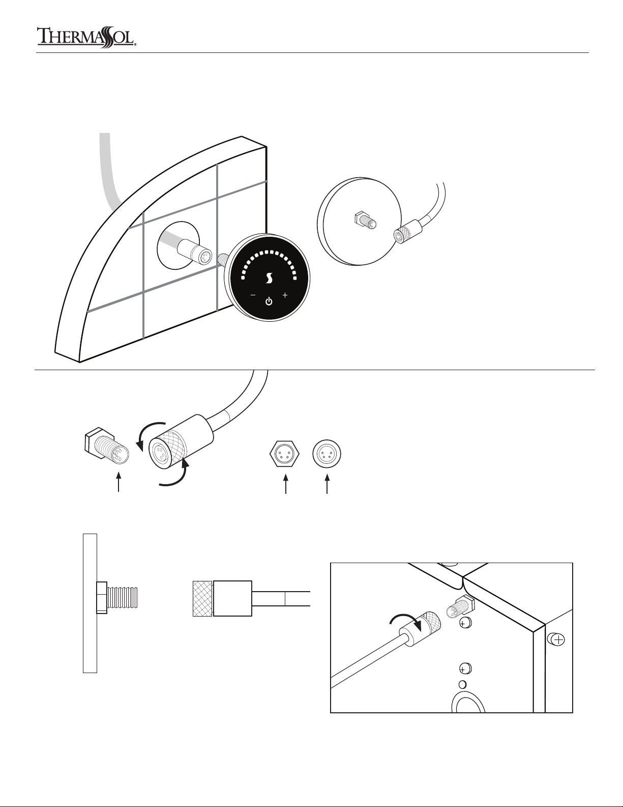
Route the data cable (included with
generator) through the nished wall
to the back side of the control.
(The other end of the cable runs to
the steam generator location.)
NOTE: It is recommended to run
the cable through electrical conduit.
Connector
Detail
Back of
control
or side of
generator
Back of
control
or side of
generator
"ON"
Turn Clockwise
Contact pins
• Do not staple, strain or damage data cable
• Align pins to receptacle visually before tightening
• Do not force plug
• Hand tighten only
"OFF" Turn
Counter Clockwise
Contact pins Contact pin
receptacle
DO NOT pinch, nail, staple, wedge, or
bind the data cable.
DO NOT wrap the data cable around
steam line or route it in a manner so
that the hot steam line could melt
the cable.
Any damage to the control cable
will result in the control not working
properly.
Carefully connect the data cable to
the generator and control BEFORE
turning power on to the generator.
Side of generator
Connect the data cable to steam generator connector.
(The other end of the cable runs to the back of the control
in the shower location.)
Read warnings on page 2. For illustrative purposes only. Consult with qualied professional for steam room construction details.
4
THERMASOL.COM I 800.776.0711
Page 5
MicroTouch Control and Steamhead Installation Instructions
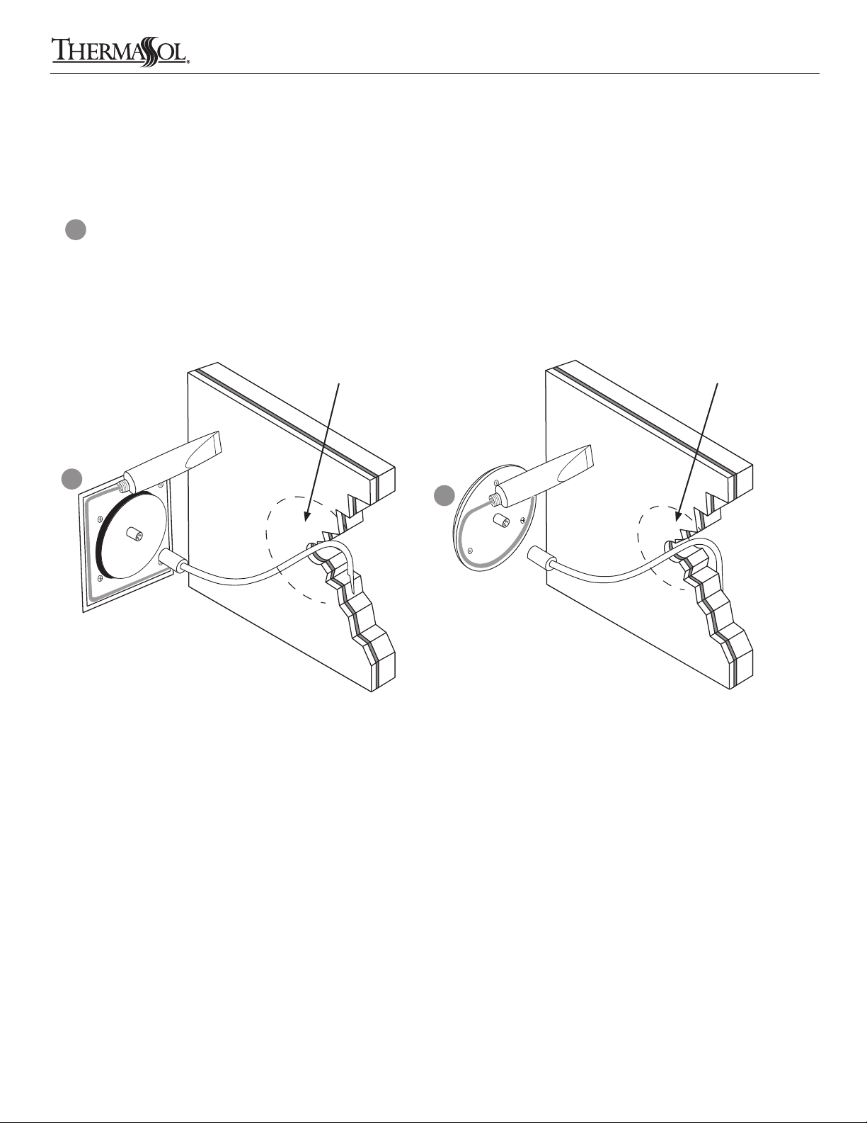
5 Sealing Control
THESE STEPS MUST BE TAKEN FOR CORRECT INSTALLATION of the control.
Coat the entire groove on the control back with supplied waterproof silicone to fully seal the control to the wall.
A
Completely seal the control to the wall so moisture does not collect behind it.
Place the control on the wall pressing rmly. (You may need to tape the control into place until the silicone dries.)
Be careful not to harm the wall or control with the tape. Let dry for 24 hours before using steam bath.
3" hole for recessed mount 1.5" hole for surface mount
A
A
Square Control
(shown)
Round Control
(shown)
Read warnings on page 2. For illustrative purposes only. Consult with qualied professional for steam room construction details.
THERMASOL.COM I 800.776.0711
5
Page 6
MicroTouch Control and Steamhead Installation Instructions
6 Steamhead Installation
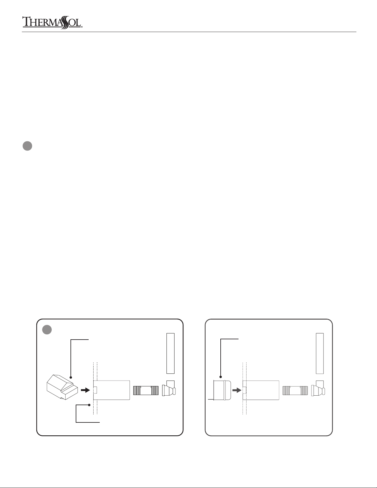
Steamhead Location
DO NOT install the steamhead near the seating area or the user.
DO NOT forget to install the steamhead rough-in tting!
Installthesteamhead24"fromtheoororbathtubrim
C
and 6" from any corner.
Steamhead is to be mounted as far as possible from
typical bathing position (seated or standing) and installed
as far from the in-shower controller as possible.
For retrot to existing nish wall:
Drill a 1-1/8" diameter hole in the shower wall or wall above
bathtub rim for the steam outlet rough-in tting and install
to be ush with the nished wall. this housing must be
sealed to the wall to not allow vapor or water behind it.
(plumbing must be done from backside of
nshed space)
For new framing: Mount and install rough-in tting to be
ush with nished wall.
Connect a 1/2" NPT brass pipe or copper tubing to
the steam outlet union (not included) on the generator
running the pipe to the steam head location in the wall
to connect with the steamhead rough-in tting. It is very
important that the pipe is rmly secured to the wall, so
that when the steamhead is installed it doesn’t push the
rough-in tting back into the wall. Install a 1/2” dropear
elbow on the end of the 1/2” pipe or tubing for the
rough-in tting.
Use the installation tool to tighten the housing in place
with a 1" socket and driver. Then insert the protective cap
into the housing.
For all the connections, use solder for copper joints and
Teon tape for pipe ttings and do not over tighten ttings.
DO NOT USE PVC CEMENT.
C
Read warnings on page 2. For illustrative purposes only. Consult with qualied professional for steam room construction details.
6
Insert installation tool and
tighten housing into place
with a 1" socket and driver
Steamhead rough-in tting
to be installed ush and
sealed to nished wall
THERMASOL.COM I 800.776.0711
Insert protective cap
into housing
Page 7
MicroTouch Control and Steamhead Installation Instructions
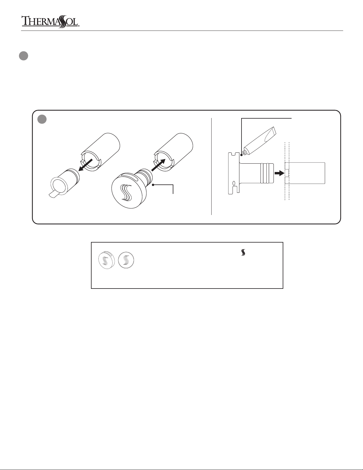
Once the shower wall is complete and the housing
D
is sealed to the wall, remove the protective cap and
insert the steamhead into housing. Use the supplied
silicone to adherethe steamhead to the wall sealing
out any water from getting behind the head.
D
Remove protective
cap from housing
Insert steamhead
into housing
Use supplied o-ring lubricant to assist in steam head
installation. A very small amount is all that is need directly
on the o-rings.
Apply a small amount of
supplied lubricant directly
on the o-rings.
Use the supplied
silicone to adhere
the steamhead to
the wall
Allow24hoursforsiliconetodrybeforeuse
Upon nal installation mount steamhead with facing up
to allow aromatherapy well to dispense steam.
For detailed installation instructions of the steamhead please
see Installation section in thermasol.com/customer-support
Read warnings on page 2. For illustrative purposes only. Consult with qualied professional for steam room construction details.
THERMASOL.COM I 800.776.0711
7
Page 8
MicroTouch Control and Steamhead Installation Instructions
7 Operation
Taking a Steam Bath
A
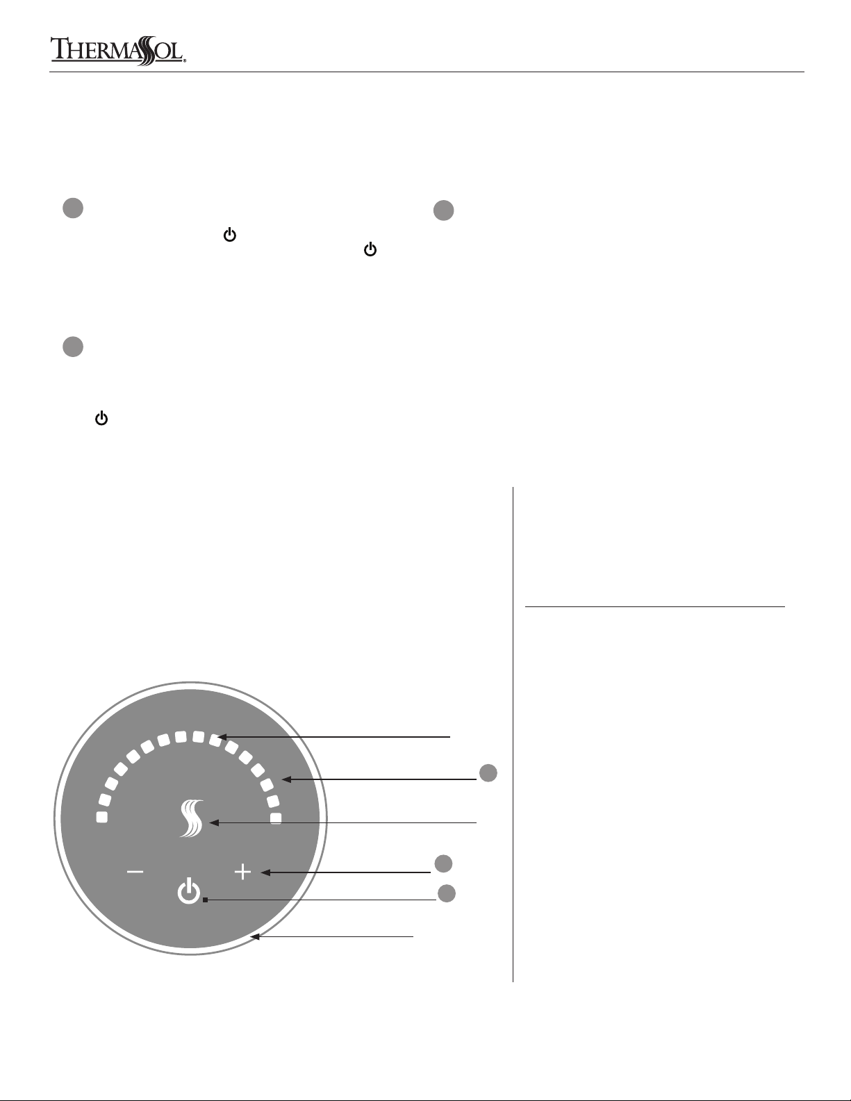
On your ThermaSol MicroTouch Control, touch and
release the power icon twice to power on. To turn off
the steam unit touch and release the power icon once.
Power on is veried when the control face shows lit LEDs
and turns dark if power is off.
C
Power Flush
ThermaSol’s internal diagnostic system will alert you
when a Power Flush cleaning is needed (Maintenance
mode) by LEDs running counterclockwise.
A steam session lasts 45 minutes and is loaded with
previously saved temperature set point.
B
Setting or Changing the Temperature Set Point
Set the temperature of your ThermaSol steam shower
by using the lit plus + or minus – symbols, which are
located immediately to the left and to the right of the
power icon. An arc array of lit squares will appear
from left to right.
Increasethetemperaturebytouching+symbol
until desired temperature is displayed by the blue LED
lights running clockwise to indicate an increase
in temperature. Press and hold the + symbol to change
the setting faster.
Reducethetemperaturebytouching–symbol
and the array of LEDs will begin to turn off. Press and
hold the – symbol to change the setting faster.
Be careful not to touch both the + and – buttons at the
same time.
Bright LED Display
Capacitive Touch Area
Maintenance mode indicated
by counter clockwise LEDs
Built-in Infrared
Temperature Sensing (ITS)
Temperature
Adjustment +/-
Solid Aluminum Body
Power On/Off
Start a Power Flush cleaning cycle
To start a power ush manually, press and hold the +
and – buttons for 5 seconds while the MicroTouch is
in the on state. To indicate that the unit is in power ush
mode, the array LEDs will ash in a clockwise direction.
Error Codes
The simplied error code reporting
system includes individual codes for
any applicable system fault.
+ –
The number of lit LEDs on the temperature
scale shows the type of error.
1 light Room Over Temperature Error
2 lights Reserved for Factory Use
3 lights Malfunction DOWN Button Error
4 lights Malfunction POWER Button Error
C
5 lights Malfunction UP Button Error
6 lights Low AC Voltage Error
7 lights Bad Connection / Low Water Error
B
A
8 lights Reserved for Factory Use
9 lights Reserved for Factory Use
10 lights Communication Error
LEDs will blink to show an error
Read warnings on page 2. For illustrative purposes only. Consult with qualied professional for steam room construction details.
8
THERMASOL.COM I 800.776.0711
Page 9

MicroTouch Control and Steamhead Installation Instructions
Read warnings on page 2. For illustrative purposes only. Consult with qualied professional for steam room construction details.
THERMASOL.COM I 800.776.0711
9
Page 10

1958 STEAM WAY ROUND ROCK, TX 78665
PHONE: 800.776.0711 | FAX: 800.556.5257 | WWW.THERMASOL.COM
81181 C
 Loading...