


Installation and
User Manual

TABLE OF CONTENTS
INTRODUCTION............................................................................................
..........................
.. 2 1-WARNINGS AND WARRANTY TERMS............................................
...
....................
........
.
........
3 2-
INSTALLATION INSTRUCTIONS.................................................................
.......................
....... 7 3-DRAWINGS AND TECHNICAL SPECIFICATIONS.........................................
......
................
........
16 4-
INSTALLATION AND ASSEMBLY....................................................
......................
...................
18 5-
PLUMBING CONNECTION............................................................
....................
....
.................
20 6-
ELECTRICAL CONNECTIONS................................................................
.........................
..........
24 7-
INITIAL START
-
UP..........................................................................
..........
................
..............
25 8-
OPERATION...........................................................................................
..........................
..... 29 9-SAFETY DEVICES ……………………..................................................
........
.................
...................
34 10-
CLEANING AND MAINTENANCE...............................................
........................
....................
35 11-
TROUBLESHOOTING..............................................................
............
.............
.....................
40 12-
WIRING DIAGRAM.......................................................................
..........................
.............
42

INTRODUCTION
Dear Customer,
Thank you for having chosen our product.
To allow for optimal operation and for you to enjoy the warmth and sense of
wellbeing that the fire can convey in your home, we advise you to read this manual
carefully before starting up the product for the first time.
CARE OF THE MANUAL AND HOW TO CONSULT IT
Take care of this manual and keep it in an easily accessible place.
Should the manual be misplaced or ruined, request a copy from your retailer or
directly from the authorised Technical Assistance Department.
SYMBOLS USED IN THE MANUAL
ATTEN
TION:
carefully read and understand the relative message because failure to
comply with what is written can cause serious damage to the product
and put the user’s safety at risk.
INFORMATION:
failure to comply with these provisions will compromise the use of the
product.
OPERATING SEQUENCES:
sequence of buttons to be pressed to access the menus or make
adjustments.
MANUAL
carefully read this manual or the relative instructions.

SAFETY PRECAUTIONS
• Installation, electrical connection, functional verification and maintenance must only be
performed by qualified or authorised personnel.
• Install the product in accordance with all the local and national laws and Standards applicable
in the relative place, region or country.
• This product is not intended for use by persons (including children) with reduced physical,
sensory or mental capabilities, or lack of experience and knowledge, unless they are
supervised or trained on how to use the product by a person responsible for their safety.
• Only use fuel recommended by the company. The product must not be used as an incinerator. It
is strictly forbidden to use liquid fuel.
• The instructions provided in this manual must always be complied with to ensure the product
and any electronic appliances connected to it are used correctly and accidents are prevented.
• The user, or whoever is operating the product, must read and fully understand the contents of
this installation and use guide before performing any operation. Errors or incorrect settings can
cause hazardous conditions and/or poor operation.
• Do not use the product as a ladder or supporting structure.
• Do not place laundry on the product to dry. Any clothes horses or similar objects must be kept at
a safe distance from the product. Fire hazard.
• All liability for improper use of the product is entirely borne by the user and relieves the
Manufacturer from any civil and criminal liability.
• Any type of tampering or unauthorised replacement with non-original spare parts could be
hazardous for the operator's safety and relieve the company from any civil and criminal liability.
• Most of the surfaces of the product are very hot (door, handle, glass, smoke outlet pipes, etc.).
Avoid contact with these parts unless adequate protective clothing is worn or appropriate means
are used, such as heat protective gloves or cold handle type operating systems.
• It is forbidden to operate the product with the door open or the glass broken.
• The product must be powered by a system that is equipped with an effective earth system.
• Switch the product off in the event of a fault or malfunctioning.
• Accumulated unburned pellets in the burner after each "failed start-up" must be removed before
starting up again.
• Do not wash the product with water. The water could get inside the unit and damage the
electrical insulation and cause electric shocks.
• Do not stand in front of the product for a long time. Do not overheat the room where the
product is installed. This could cause injuries and health problems.
• Do not put any fuel other than wood pellets in the hopper.
• Install the product in rooms that are adequately protected against fire and equipped with all the
utilities such as supplies (air and electricity) and smoke outlets.
• If a fire breaks out inside the chimney, switch the appliance off, disconnect it from the mains and
do not open the door. Then contact the competent authorities.
• The product and the ceramic/serpentine cladding must be stored in a place where there is no
humidity and must not be exposed to the elements.
• It is recommended not to remove the feet that support the product in order to guarantee
adequate insulation, especially if the flooring is made of flammable material.
• If the ignition system is faulty, do not force ignition with flammable materials.
• Special maintenance must only be performed by authorised and qualified personnel.
• Assess the static conditions of the surface on which the weight of the product will rest and
provide suitable insulation if it is made of flammable material (e.g. wood, fitted carpet or plastic).
1
WARNINGS AND WARRANTY TERMS

INFORMATION:
Please contact the retailer or qualified personnel authorised by the company to resolve a problem.
• Only fuel stipulated by the company must be used.
• Check and clean the smoke outlet pipes regularly (connection with the product).
• The product is not a cooking appliance.
• Always keep the cover of the fuel hopper closed.
• Keep this instruction manual in a safe place as it must accompany the product throughout its
working life. If it is sold or transferred
• to another user, always make sure that the manual accompanies the product.
INTENDED USE
The product only works with wood pellets and must be installed indoors.
WARRANTY CONDITIONS
The company provides a product warranty, excluding the parts subject to normal wear stipulated
below, for a period of two years from the date of purchase, which is proven by a supporting
document that contains the name of the seller and the date when the sale took place. Warranty
cover is valid if the completed warranty is returned within 8 days and the product is installed and
tested by a qualified installer, according to the detailed instructions provided in the instruction
manual supplied with the product.
The term ‘warranty’ refers to the (free-of-charge) replacement or repairs of parts acknowledged to
be faulty due to manufacturing defects.
RESTRICTIONS
The above-mentioned warranty does not cover parts of electrical and electronic components and
fans, which are covered for two years from when the product is purchased, proof of which is
provided as specified above. The warranty does not cover parts subject to normal wear, such as:
gaskets, glass and all parts that can be removed from the firebox. Replaced parts will be covered by
the warranty for the remaining period of the warranty in force as from the date of purchase of the
product.
EXCLUSIONS
Variations in colour of the painted do not constitute grounds for a claim as they are natural
characteristics of the material and product use.
The warranty does not cover any part that may be faulty as a result of negligence or careless use,
incorrect maintenance or installation that does not comply with the company's instructions (see the
relative chapters in this user manual).
The company declines all liability for any damage which may be caused, directly or indirectly, to
persons, animals or objects as a consequence of non compliance with all the prescriptions specified
in the manual, especially warnings regarding installation, use and maintenance of the appliance.
If the product does not work correctly, contact your local retailer and/or importer. Damage caused
during transport and/or when handled is excluded from the warranty.The supplied installation guide
is the only reference for installation and product use.

The warranty will be rendered null and void in the event of damage caused by tampering,
atmospheric agents, natural disasters, electrical discharges, fire, defects in the electrical system, and
maintenance not being performed at all or as indicated by the manufacturer.
INTERVENTION REQUEST
The company declines all liability if the product and any other accessory is used
incorrectly or altered without authorisation.
All parts must be replaced with original spare parts.
The request must be sent to the retailer who will forward it to the Technical Assistance
Service.
SPARE PARTS
Only use original spare parts. The retailer or service centre can provide all the useful information
regarding spare parts.
It is recommended not to wait for the parts to be worn before having them replaced. It is important
to perform regular maintenance.
PRECAUTIONS FOR CORRECT DISPOSAL OF THE PRODUCT IN ACCORDANCE WITH THE EUROPEAN
DIRECTIVE 2002/96/EC AND ITS SUBSEQUENT AMENDMENT 2003/108 EC.
At the end of its working life, the product must not be disposed of as urban waste.
It must be taken to a special differentiated waste collection centre set up by the local authorities or
to a retailer that provides this service.
Disposing of the product separately prevents possible negative consequences for the environment
and health deriving from inappropriate disposal and allows to recycle its materials in order to obtain
significant savings in energy and resources.
As a reminder of the need to dispose of appliances separately, the product is marked with a crossedout wheeled dustbin.

The product is a stove designed for operation with wood pellets. It must be installed in compliance
with the regulations listed below:
• EN 10683 (2012) heat generators fed with wood and other solid fuels: installation.
The chimneys must be in compliance with:
• EN 13063-1 and EN 13063-2, EN 1457, EN 1806 in the event of non-metallic chimneys:
• EN 13384-1 (13384) chimneys. Thermal and fluid dynamic calculation methods.
• EN 1443 (2005) chimneys: general requirements.
• EN 1457 (2012) chimneys: clay/ceramic flue liners.
The installation procedure requires the heating system diagram, prepared in compliance with the
standard and local recommendations in force as follows:
• For the heating system - EN 303-5/2000 - “Heating boilers. Part 5: Heating boilers for solid
fuels, hand and automatically stoked, with a nominal heat output of up to 300 kW.
Terminology, requirements, testing and marking”.
• Local requirements for the connection to the chimney.
• Local requirements for fire regulations.
• For the power circuit - EN 60335-1/2008- “Safety of household and similar electrical
appliances, Part 1 - General Requirements”.
One must also bear in mind all laws and national, regional, provincial and town council Standards
present in the country in which the appliance has been installed.
PELLETS
Wood pellets are manufactured by hot-extruding compressed sawdust which is produced during the
processing of natural dried wood (without paints). The compactness of the material is guaranteed by
the lignin contained in the wood itself and allows pellets to be produced without glue or binders.
The market offers different types of pellets with characteristics that vary according to the wood
mixtures used. The diameter varies between 6 and 8 mm, with a standard length ranging from 5 to
30 mm. Good quality pellets have a density that varies between 600 and over 750 kg/m3, with a
moisture content that ranges from 5% to 8% of its weight.
Pellets have technical advantages besides being an ecological fuel, as the wood residue is used
completely, thereby achieving cleaner combustion than that of fossil fuels.
Good-quality wood has a calorific value of 4.4 kW/kg (15% moisture, after about 18 months of
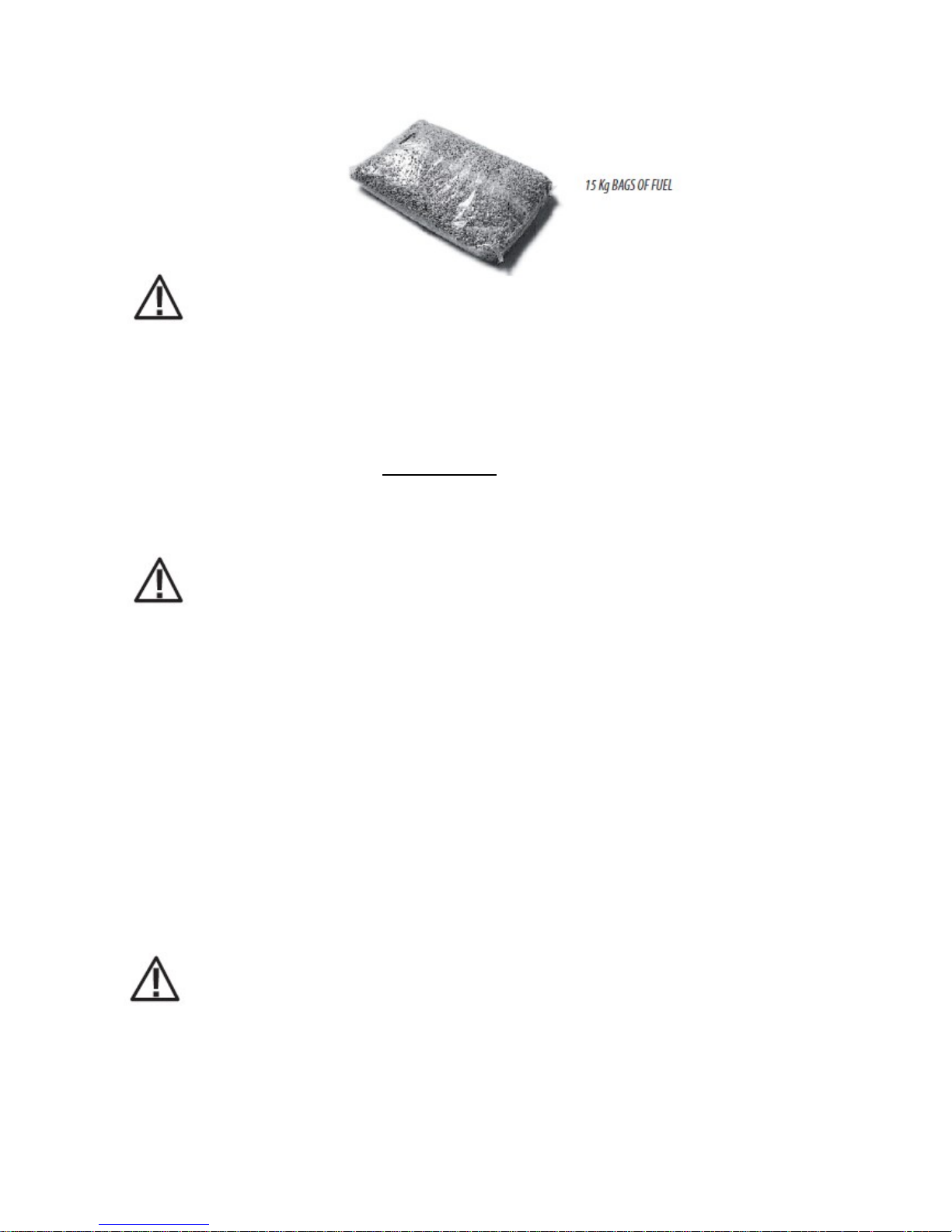
seasoning), whereas that of pellets is 4.9 kW/kg. To ensure good combustion, the pellets must be
stored in a dry place and protected from dirt. Pellets are usually supplied in 15 kg bags, therefore,
storing them is very convenient.
Good quality pellets guarantee good combustion, thereby decreasing harmful emissions into the
atmosphere.
2
INSTALLATION INSTRUCTIONS
The poorer the quality of the fuel, the more often the internal parts of the brazier and
combustion chamber must be cleaned.
The pellet used must comply with the features described by Standards:
EN PLUS - UNI EN 16961 - 2 class A1 or A2
Ö-NORM M 7135
DIN PLUS 51731
We recommend using pellets with a diameter of 6mm with its products.
Pellet storage
To guarantee combustion without problems, the pellets must be kept in a dry place.
Poor quality pellets or others that do not comply with that specified previously
compromises the operation of your product and can therefore render the warranty and
product liability null and void.
PRECAUTIONS REGARDING INSTALLATION
The product must be installed in a suitable place for it to be regularly opened and routine
maintenance to be performed. The site must be:
• Compliant for proper operation.
• Equipped with an adequate smoke expulsion system.
• Equipped with ventilation intake from outside.
• Equipped with 230V 50 Hz power supply with an EC compliant earth system.
The product must be connected to a chimney or an internal or external vertical duct that complies
with the regulations in force. The product must be positioned in such a way that the electrical
socket is accessible.
IMPORTANT!
The product must be connected to a chimney or a vertical duct that can expel the smoke at
the highest point of the building. In any case smoke derives from combustion of types of
wood and if it comes in contact with or close to walls, these can become dirty. Moreover,
utmost attention is required as they are almost invisible but very hot and can cause burns.
The holes of the external air inlet and the smoke outlet pipe must be drilled before positioning the
product.

THE OPERATING ENVIRONMENT
For correct operation and even distribution of heat, the product must be placed where the air
required for combustion can flow.
The volume of the room should be no less than 15 m3.
Air must enter through permanent openings made in the walls (near the product) that reach
outwards with a minimum section of 100 cm2 without the protective grille. These openings (air
inlets) must be made in such a way that it is impossible for them to be obstructed in any way.
Air can also be drawn from adjacent rooms to the one that is to be ventilated, provided they have an
external air inlet and are not used as a bedroom or bathroom or where there is a fire hazard, such as:
garages, timber storerooms, warehouses of flammable materials, observing under all circumstances
the provisions of all the applicable standards in force.
If the product is placed too close to the wall it could cause overheating and damage the
plaster (yellowing, cracking, etc.).
POSITIONING AND RESTRICTIONS
In the case of simultaneous installation with other heating appliances, provide appropriate air inlets
for each one (according to the instructions of each product).
The product cannot be installed (except for sealed or closed operation appliances with
external ducted combustion air intake):
in bedrooms or bathrooms;
in rooms where there are liquid fuel appliances with continuous or intermittent operation
that draw the combustion air from the room they are installed in;
in rooms where there are B-type gas heating appliances, with or without domestic hot
water production and interconnecting rooms;
where another heating appliance is installed without an independent air flow.
It is forbidden to place the product in an explosive atmosphere.
BOILER ROOM
Check that the room meets the requirements and characteristics in compliance with the standards in
force. The room must also have suitable ventilation required for proper combustion. One must
therefore make openings in the room walls that meet the following requirements:
• They must have a section of at least 6 cm2 per each 1 kW (859.64 kcal/h). The minimum opening
section must in any case not be below 100 cm2. The section may also be calculated using the
following relation:
S = K * Q . 100 cm2
Where “S” is expressed in cm2, “Q” in kW, “K” = 6 cm2/kW
• The opening must be positioned in the lower part of an outer wall, preferably opposite to that in
which the smoke evacuation duct is located.

MINIMUM DISTANCES
Room ventilation can only be set towards the rear wall if there is adequate insulated
ducting of the hot air flow.
If particularly delicate objects are present, such as furniture, curtains or sofas the distance of the
product must be significantly increased.
If the floor is made of wood, it is recommended to place a floor protection in accordance
with the Standards in force in the country of installation.
Heat-sensitive or flammable objects cannot be placed near the product. Keep such
objects at a minimum distance of 80 cm from the outermost point of the product.
CONNECTION OF THE SMOKE EXHAUST DUCT
When making the hole for the passage of the smoke
discharge pipe, one must take into account the
possible presence of flammable materials. If the hole
must be made through a wooden wall or
thermolabile material, the INSTALLER MUST first of
all use the appropriate wall fitting (minimum
diameter 13 cm) and suitably insulate the pipe of the
product that passes through it using adequate
insulating materials (1.3 - 5 cm thick with minimum
thermal conductivity 0.07 W/m°K).
The same minimum distance must be applied if the
pipe of the product must pass through vertical or
horizontal sections near the thermolabile wall. It is
recommended to use an insulated double-wall pipe in
external sections in order to prevent condensation
from forming.
The combustion chamber works in negative pressure.
REAR VIEW OF A PELLET STOVE
1) SMOKE OUTLET
2) COMBUSTION AIR INLET
Always use pipes and fittings with appropriate seals that guarantee tightness.
REFERENCES
FLAMMAB
LE OBJECTS
NON
-
FLAMMABLE
A 200 mm 100 mm
B 200 mm 100 mm

It must be possible to inspect all sections of the flue duct and they must be removable for periodic
internal cleaning (T-fitting with inspection hole).
Position the product considering all the above requirements and instructions.
IMPORTANT!
The following conditions must be complied with when connecting the appliance to the
chimney:
The smoke duct must be at least category T200 (or higher if required by the smoke
temperature of the appliance) and P1-type (airtight).
All 90° angles (max. 3) in the smoke exhaust duct must be preferably fitted with the
relative T-fittings with inspection hole. (See pellet product accessories).
It is strictly forbidden to fit a mesh at the end of the exhaust pipe as it could cause the
product to malfunction (due to clogging).
It is forbidden to use counter-sloping pipes.
The horizontal section of the smoke duct must not be longer than 2-3 m.
It is also recommended not to exceed 6 metres in length with the pipe Ø 80 mm.
The smoke duct must not cross rooms in which it is forbidden to install combustion
appliances.

FRESH AIR INTAKE
To ensure trouble
-
free operation the stove/fireplace
must have the necessary air available for combustion
and this is provided through the fresh air intake.
The fresh air intake must:
have a total free cross section at least equal to the
size given in the paragraph “TECHNICAL DATA”;
be protected by a grille or suitable guard provided
it does not reduce the minimum recommended
section;
be in a position whereby it cannot be obstructed.
The airflow
necessary for the fire may be obtained in
different ways:
through a fresh air intake direct into the room of
installation;
with ducting through pipes direct to the room of
installation, increasing the recommended minimum
free cross section by at least 15%;
from an adjacent room to the place of installation
provided this air flows freely through permanent
apertures communicating with the outside.
The adjacent room from which air is taken
must not have a low pressure compared to
the exterior due to a counter draught
caused by the presence in that room of another
appliance in use or of a suction device.
The permanent apertures in the adjacent room must
comply with the requirements given above.
Combustion air must not be taken from adjacent
rooms used as a garage or a combustible materials
store or for activities posing a fire hazard.

CONNECTION TO THE EXTERNAL AIR INLET
It is essential for the room where the product is installed to be adequately ventilated in order to
guarantee sufficient air for proper combustion in the appliance. This is possible by means of suitable
ventilation openings in the room itself or in an interconnected room through a permanent opening
between the rooms (room ventilation is excluded in the case of installation with Oyster technology,
where combustion air is ducted directly from outside)
For this purpose, drill a hole on the outer wall close to the product with a minimum section of 80 cm²
(11 cm in diameter or 10x10 cm if rectangular, considering the protective grilles), protected by a
grille on the outside.
The air inlet must also:
• be protected with a grid, metal mesh, etc. without reducing the net section.
• Be positioned in such a way so as not to be obstructed.
• Allow maintenance to be performed.
• Be directly interconnected with the room where the product is installed.
• In the case of ducting, up to 3.5 linear metres, increase the cross-section by about 5%,
whereas for longer ducts, increase it by 15%.
Remember that the ventilation grilles always show the useful section in cm2 on one
side. When choosing the grille and size of the hole, check that the useful section of the
grille is larger or equal to the section required by the company for product operation.
IMPORTANT!
The air flow can also be drawn from an adjacent room to that of the room where the
product is installed, provided the air can flow freely through permanent openings
interconnected with the outside; air inlets connected to thermal units, garages, kitchens
or bathrooms must be avoided.
CONNECTION TO THE CHIMNEY
The chimney is the fundamental element for smoke expulsion and must therefore comply with the
following requirements:
• be waterproof and thermally insulated.
• Be made of suitable materials that resist mechanical stress over time, heat, the effects of the
combustion products and any possible condensation.
• Have a vertical set-up with deviations from the axis of no more than 45° and free of bottlenecks.
• Must be suitable for the specific operating conditions of the product and have the CE marking
(EN1856-1, EN1443).
• Must be adequately sized for the draught/smoke expulsion requirements that are necessary for the
product to operate correctly (EN13384-1).
• The internal section is preferably circular.
• In the case of a pre-existing product that has been used, it must be cleaned.
• The chimney must not be shared with other appliances.
The chimney is fundamental for correct operation and safety of your product.
1) WINDPROOF CHIMNEY POT 2) CHIMNEY 3) INSPECTION HOLE
Use adequate instruments to verify that there is a minimum draught of 5 Pa.
Set-up an inspection hole at the bottom of the chimney to perform periodic checks
and cleaning, which must be done annually.
The connection to the chimney must be sealed and the fittings and pipes
recommended by us must be used (CE marked, EN1856-2 with the minimum requisites: T200
and P1).
You must ensure that a windproof chimneypot is installed in accordance with the regulations in
force.This type of connection guarantees smoke expulsion even in the event of a temporary
power cut.
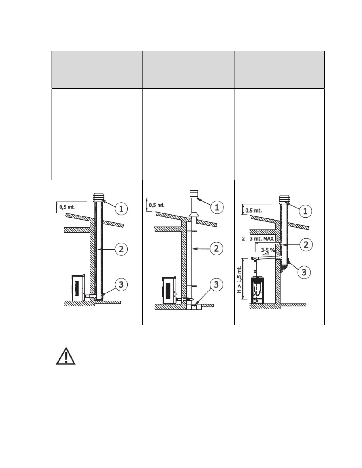
CONNECTION TO THE CHIMNEY
CONNECTION TO AN
EXTERNAL DUCT WITH AN
INSULATED OR DOUBLE-WALL
PIPE
CONNECTION TO THE CHIMNEY
The chimney's internal
dimensions must not exceed
20x20 cm or 20 cm diameter; in
the event of bigger sizes or bad
chimney conditions (e.g. cracks,
poor insulation, etc.), it is
advisable to fit a stainless steel
pipe of suitable diameter
throughout the length of the
chimney right to the top.
The minimum internal dimensions
of the external duct must be
10x10 cm or 10 cm
in diameter and must not exceed
20x20 cm or 20 cm in diameter.
Only stainless steel insulated
(double-wall) pipes must be used,
which are smooth on the inside
and fixed to the wall. Flexible
stainless steel pipes must not be
used.
The connection between the
product and the chimney or the
smoke duct must not have an
inclination that is less than 3% in
the horizontal sections, which
must have a maximum overall
length of 2/3 m. The vertical
section between one T-fitting and
another (angle) must not be less
than 1.5 m.

CHIMNEY STACK
The chimney stack is a device fitted on the top of
the chimney that is designed to
aid dispersion of the products of combustion in the
atmosphere.
The chimney stack must comply with the following
requirements:
it must have an internal section and shape
the same as the flue (A);
it must have a useful outlet section (B) of
not less than twice that of the flue (A);
the part of the chimney that emerges from
the roof or remains in contact with the
outside (e.g. in the case of a flat roof), must
be covered with brick or tile elements and
in any case well insulated;
it must be built in such a way as to prevent
the penetration of rain, snow and foreign
matter into the flue and to ensure that in
the event of winds from all directions and
angle, discharge of the combustion
products is assured (chimney stack with
down-draught cowl).

No Description
1
Top cover
2
Smoke hood cover
3 Turbulators
4
Cast iron top plate
5
Glass
6
Cast iron door
7
Grate
8
Ash pan
9
Smoke chamber plate
10
Display
11
Air valve
12
Sensor pocket
13
Safety Thermostat
14
Air pressure switch
15
Electronic board
16
Water pressure switch
17
Pump
18
Expansion tank
No
Description
19
Tube cleaning
rod 20 Vermiculite board (back panel)
21
Auger motor
22
Igniter
23
Extraction Fan
2
DRAWINGS AND TECHNICAL SPECIFICATIONS

12 16 24
Thermal power (min/max) kW 5 / 12 6,7 / 16 10 / 24
Thermal power of fluid (water) (min/max) kW 4,1 / 9,7 5,4 / 12,9 8,1 / 19,4
Hourly fuel co nsumption (min/max) kg/h 1,1 / 2,6 1,5 / 3,6 2,3 / 5,4
Efficiency % 89 90 90
CO content (with 13% O2) min/max % 0,02 / 0,0025 0,02 / 0,0025 0,02 / 0,003
Flue temp erature (min/max) °C 125 / 180 110 / 170 85 / 140
Minimum draught Pa
Maximum power rating W
Power rating at work W
Supp ly voltage and frequency V/Hz
Fuel tank capacity kg 27 32 36
Expansion tank ca pacity lt
Maximum working pressure bar
Flow / Re turn (F / R ) R
Safety valve (SV) R
External dimensio ns
H mm 1050 1120 1180
H1 mm
H2 mm
H3 mm
W mm 600
W1 mm 110
L mm 610
D mm
Fresh air intake dia meter mm
230/50
6
3/4"
Ø 50
Mo del HYDRA
Types
320
10
400
160
3
3/4"
Ø 80
560
540
80
250
50

PREPARATION AND UNPACKING
The stove is supplied complete with all its electrical and mechanical components and factory-tested.
Open the package and cut the strip that fasten the stove to the pallet.
Set the stove in the pre-selected place, making sure this complies with the requirements. The stove
body or unit must always be kept in a vertical position when handled and moved by using carts only.
Pay particular attention that its door and its glass are protected from knocks that might compromise
their integrity.
Always handle the product with care. If possible, unpack the stove near the chosen place of
installation. The materials that make up the packaging are neither toxic nor harmful, and so require
no particular disposal measures.
After removing the packaging make sure that the stove is complete and not damaged. if in doubt
contact the dealer.
The product packaging contains the following documents and accessories:
• user manual
• warranty
• allen wrench
• tube cleaning tool
REQUIREMENTS FOR SYSTEM INSTALLATION
the minimum distance in front of the product to allow for cleaning, maintenance, etc. must be
at least 1000 mm;
the minimum admitted distance between the rear of the product and the wall must be 400 mm;
4
INSTALLATION AND ASSEMBLY

the minimum distance between the upper part of the product and a wall (ceiling) must be of 400
mm to ensure easy access for heat exchanger cleaning and maintenance (for example to remove
ashes);
the minimum distance between the product and wall must be 300 mm.
It is essential to make ventilation holes connecting to the exterior and in compliance with Standard
UNI 10683, with the following characteristics:
1. They must have a section of at least 100 cm2;
2. They must be made at a height close to that of the floor;
3. They must be adequately protected by wire mesh or grille, provided it does not reduce the
minimum passage section;
4. They must be positioned in such a way as not to be clogged.
Proper air flow can also be guaranteed by openings to an adjacent room, as long as it
has direct ventilation and is not an environment with danger of fire, such as storage
rooms, garages or warehouses as regulated by Standard UNI 10683.
It is good practice to install the boiler in rooms in which there are no leaking devices with respect to
the room or appliances which may cause depression in the room itself with respect to the external
environment thus causing poor draught problems of the smoke evacuation system (UNI 10683).

IMPORTANT!
If installation of the product involves interaction with another, pre-existing system
complete with heating equipment (gas boiler, methane boiler, diesel boiler, etc.),
contact qualified personnel, who subsequently will be responsible for conformity of the
system in compliance with the applicable law in force.
The Company declines all responsibility for damage to persons or things in the event of failed or
incorrect operation, if the aforementioned warnings are not complied with.
Make the connections to the corresponding fittings shown in the diagram above. Make sure the
pipes are not placed under tension or undersized.
IMPORTANT!!!
5
PLUMBING CONNECTION

FLUSH THE ENTIRE SYSTEM BEFORE CONNECTING THE BOILER IN ORDER TO REMOVE
RESIDUES AND DEPOSITS.
Always install gate valves upstream from the boiler so as to disconnect it from the plumbing
system should it be necessary to move it, or when it requires routine and/or special maintenance.
Connect the boiler using hoses so that the boiler is not too strictly connected to the system, and to
allow slight movements.
SYSTEM FILLING
Filling must be carried out slowly so that air bubbles can get out via the purposely placed outlets on
the heating system. In closed circuit heating systems the loading pressure of the system when cold
and the expansion tank preloading pressure must be the same.
In open tank heating systems, there is direct contact between the circulating liquid and air.
During the heating season the end user must regularly check the level of water circulating in
the expansion tank. The content of water in the recycling system must be kept constant.
Practical experience demonstrates that the water level must be inspected regularly every 14
days to maintain the water content almost constant. In the event one needs to add water
one must carry out the filling process when the boiler has cooled down to room
temperature. These precautions aim to prevent the onset of a thermal stress of the steel
body of the boiler.
In systems equipped with an open tank the water pressure in the boiler - when the system is
cold - must not fall below 0.3 bar;
The water used for filling the heating system must be decontaminated and without air.
Attention!
Do not mix the heating water with antifreeze or anticorrosion substances in the wrong
concentrations! It can damage the seals and cause the onset of noise during operation.
The manufacturer declines all responsibility if the damage caused to persons, animals or
things is a result of failure to comply with the above.
Once all plumbing connections have been carried out, proceed with the inspection of the seals
under pressure, by filling the boiler.
This operation must be done carefully observing the following steps:
open the radiator, boiler and system air valves;
gradually open the system filling tap making sure that any automatic air valves installed on
the system work properly;
close the radiator air valves as soon as water starts to come out;
on the system pressure gauge check that the pressure reaches a value of approximately 1 bar
(applicable only for systems equipped with a closed tank - refer to any standards or local
regulations that allow it); for open tank systems refilling takes place automatically via the
same tank;
close the system loading tap and then bleed air again via the radiator air valves;
check tightness of all connections;
after having started the boiler for the first time and heated up the system, stop the pumps
and repeat the air bleeding operations;

let the system cool down and if needed take the water pressure back to 1 bar (applicable
only for systems equipped with a closed tank - refer to any standards or local regulations that
allow it); for open tank systems refilling takes place automatically via the same tank.
NOTE
In systems equipped with a closed tank, where possible, the water pressure in the
heating system - when the system is cold - must be no less than 1 bar; if under this value,
act on the system filling tap. The operation must be carried out when the system is cold.
The system pressure gauge enables to monitor the pressure in the circuit.
To fill the system, the boiler is fitted with a tap (4), with a check valve, to load the heating system
manually. During this operation, any air in the system is released via the air valve located in the
upper part of the boiler.
To ensure the valve vents, it is advisable to loosen the top cap (see figure).
The filling pressure of the system WHEN COLD must be 1 bar.
Upon completion of this filling operation, always close the tap.
Air valve

HYDRAULIC SYSTEM
6
ELECTRICAL CONNECTIONS

Electrical safety of the system is ensured only when it is properly connected to an efficient earthing
system made in compliance with the safety standards in force: gas, water or heating systems pipes
are not suitable as earth connections.
One must check this essential safety requirement; if in doubt, request an accurate inspection of the
electrical system to be carried out by qualified personnel, because the boiler manufacturer is not
responsible for any damage caused by failure to earth the system.
Have professionally qualified personnel check the electrical system is suitable for the maximum
power absorbed by the heating system, ensuring in particular that the diameter of cables is
appropriate for the power absorbed by the loads.
The use of any component that is powered by electricity entails compliance with some basic rules
such as:
• do not touch the appliance with wet and/or damp body parts and/or bare feet;
• do not pull the electric cables;
• do not leave the appliance exposed to weathering (rain, sun, etc.);
• do not allow the appliance to be used by children or inexperienced persons.
230V electrical power supply connection
Installation of the boiler accessory electrical components requires electrical connection to a 230 V –
50 Hz mains.
Hazard!
Electrical installation must be carried out by a qualified technician only.
Before performing connections or any operation on the electrical parts, always
disconnect the power supply and make sure it cannot be accidentally reconnected.
Please note that the boiler electrical power line must be fitted with a bipolar switch
with a contact gap greater than 3 mm, easy to access, in order to make any maintenance
operations quick and safe.
The power cable must be replaced by authorised technical personnel.
If the supply cord is damaged, it must be replaced by a special cord or assembly available from
the manufacturer or its service agent.
ELECTRICAL CONNECTION
First connect the power cable to the side of the stove and then to a wall socket. The main switch at
the side must only be activated to switch the stove on; otherwise, it is advisable to keep it off.
It is recommended to disconnect the power cable when the stove is not used.
Electrical connection of the stove

BEFORE START-UP
GENERAL PRECAUTIONS
Remove all components that could burn from the brazier and glass (manual, various adhesive labels
and any polystyrene).
Check that the brazier is positioned correctly and rests properly on the base.
After a long period of inactivity, remove any pellets left in the hopper (using a vacuum
cleaner with a long pipe ), as they could have absorbed moisture, thereby altering their
original characteristics and no longer being suitable for combustion.
The first start-up may not be successful as the feed screw is empty and does not always
manage to load the required amount of pellets in the brazier in time for the fire to be
regularly ignited.
CANCEL THE FAILED START-UP ALARM STATUS BY PRESSING AND HOLDING KEY 1 (ESC).
REMOVE THE PELLETS FROM THE BRAZIER AND REPEAT START-UP.
If a flame does not ignite after a number of failed start-ups, even though the pellet supply is correct,
make sure the brazier is set in place correctly, which must be interlocked in its seat and free from any
ash deposits. If no anomaly is found during this inspection, there may be a problem with the product
components or installation may not be correct.
REMOVE THE PELLETS FROM THE BRAZIER AND CONTACT AN AUTHORISED TECHNICIAN.
Avoid touching the stove during the initial start-up, as the paint in this stage hardens; by touching
the paint, the steel surface may be exposed.
It is good practice to guarantee effective ventilation in the room during the initial startup, as the stove will emit some smoke and smell of paint.
Do not stand close to the product and air the room. The smoke and smell of paint will disappear after
about an hour of operation, however, remember they are not harmful in any case.
The stove will be subject to expansion and contraction during the start-up and cooling phases,
therefore light creaking noises may be heard. This is absolutely normal as the structure is made of
laminated steel and must not be considered a defect.
7
INITIAL START
-
UP
It is extremely important to make sure the product is not immediately overheated and the
temperature is increased gradually, initially using low power. This will prevent damaging the ceramic
or serpentine tiles, the welds and the steel structure.
DO NOT EXPECT HEATING EFFICIENCY IMMEDIATELY!!!
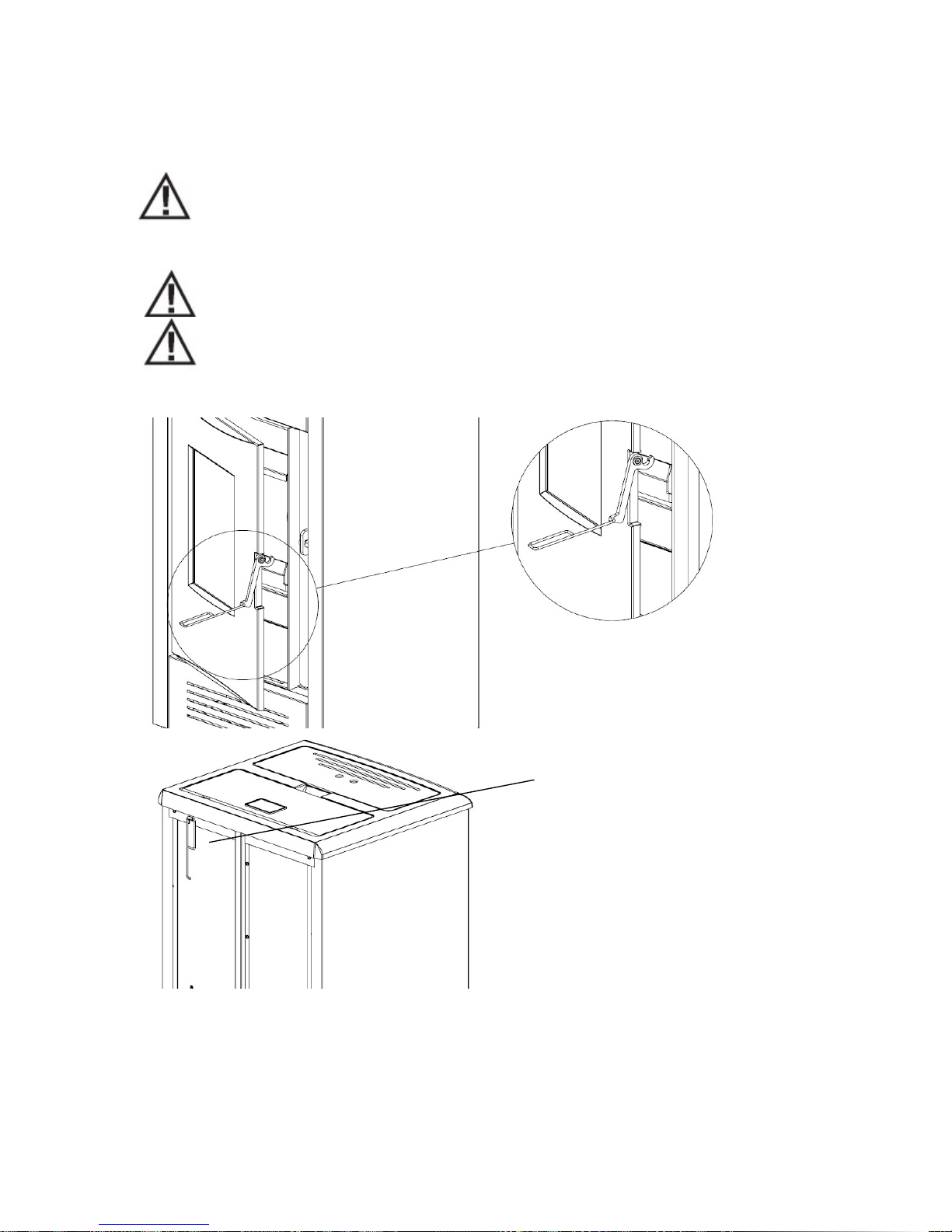
OPENING/CLOSING THE DOOR
ATTENTION!
The door must be closed properly for the stove to work correctly.
"Use suitable Personal Protective Equipment (e.g. gloves) to open the stove door.
To open the door, lift the hook, as shown in the figure"
SETTINGS TO BE CARRIED OUT BEFORE THE INITIAL START-UP
Once the power cable is connected in the rear part of the stove, turn the switch, also placed at the
rear, to position (I). To switch the stove on or off press key 1 on the control panel.
Door hook is hanged at the back of
the stove

LOADING THE PELLETS
Fuel is loaded by lifting the cover on the upper
part of the product.
Slowly pour the pellets into the
hopper.
Be careful as the cover could
become very hot.
No other type of fuel other then
pellets, in compliance with abovementioned specifications, is to be
inserted into the hopper.
EXTERNAL THERMOSTAT
The external thermostat can be used to turn the combustion system on and off. In this case
the controller ignores all internal temperature thresholds and is operating exclusively with the
thermostat input.
To configure this option; Connect the external thermostat to IN5, S5AND and GND.

ALARMS
Safety Thermostat (stove) HV1: always signalled
Block
Safety Thermostat (pellet) HV2: always signalled
Extinguishing
for Lack of Flame
Extinguishing for Water over Temperature
Extinguishing for Exhaust gas over Temperature
Encoder Error: No Encoder Signal
Encoder Error: Combustion Fan regulation failed
Failed Ignition
Lack of fuel
Led Fix Blinking
L1 Stabilization phase
Ignition Start phase
L3
Burner OFF
Extinguishing phase
L4
Work phase
Modulation/Standby
phase
L5 Auger ON
L6 Igniter Resistance ON
External Thermostat open
L7 L8
Pump
Display
Fix Blinking
D1
Work Combustion
Power Set
D2
Stove Thermostat Set
Combustion Power
Change
D3 Stove Temperature
Stove Thermostat Cha
nge D4 I indicates the Pellet
recipe 1
II indicates the Pellet
recipe 2
Button
Click [P click]
Long Pressure [P long]
P1
Display other data / Esc
Pellet recipe selection
P2
Set in to the Menu function
Burner Start / Stop
P3
Thermostat Setting/ In
creasing Value / Scroll
Menu
Pellet Loading Correction
P4
Combustion Power Setting/Decreasing
Value/Scroll Menu
8
OPERATION
Anomaly in probe control during Check Up phase
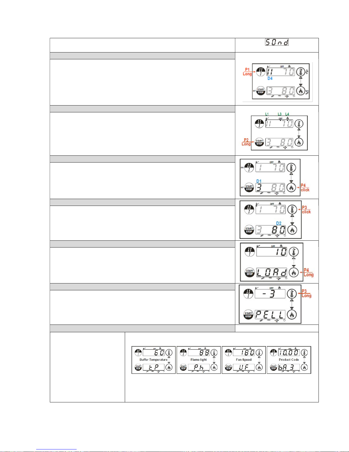
Fuel or Recipe Selection
Through a long pushing of the button P1 is changed the type of receipe.
The display D4 shows the selected recipe (I=Recipe 1; II= Recipe 2)
Ignition/Exstinguishing
The Ignition and Extinguishing are activated with a long pushing of the button P2
The Ignition is signalled by the first blinking than fix led L1
The Work state is signalled by the fix led L4
The Modulation state is signalled by the blinking L4
The Extinguishing is signalled by the blinking led L3
The Extinguishing finished = OFF state is signalled by the fix led L3
Combustion Power Setting
Click button P4: the display D1 blinks
Trough the click of the buttons P4 (increasing)or P3 (decreasing) the power is
changed according to the values available
Ex.: 1 – 2 – 3 – 4 – 5 – A (A= Automatic Combustion)
After 5 seconds the new value is memorised and the display shows as normal
Work Thermostat Setting
Click button P3: the display D2 blinks
Trough the click of the buttons P4 (increasing)or P3 (decreasing) the value of the
thermostat is changed.
After 5 seconds the new value is memorised and the display shows as normal
Manual Pellet Loading
Not applicable.
Pellet Loading Correction
The activation is with a long pushing of the button P3
The bottom display shows PELL, the upper display shows the blinking value
With buttons P3 / P4 the blinking value increases or decreases
The values are between the range– 7 ÷ 7.The default value is ‘0’
After 5 seconds the new value is memorised and the display shows as normal
Display
With a click sequence of P1
tP= Buffer Probe Temperature
(if present)
UF= Combustion Fan Speed
[RPM/Volt]
tF= Exhaust temperature [°C]
+ Product Code
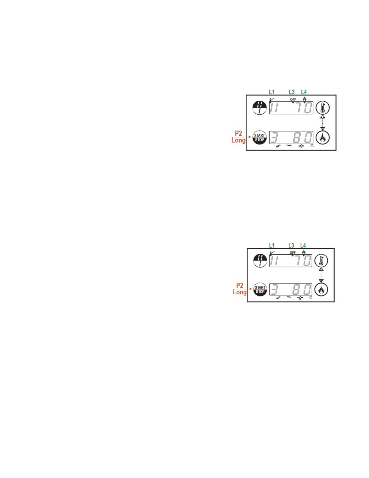
START-UP
At the first loading the feed screw may be empty. So start the stove and wait until the first pellet
starts falling into the burning pot. Then stop the stove by pressing long to the P2 button. Now you
can restart the stove again.
Switch ON the stove
Check the stove to be in “OFF” position (fixed led L3).
Switch ON the stove with a long pushing of the button P2.
Led status when the stove is ON:
1. The Ignition is signalled by the first blinking than fix led L1
2. The Work state is signalled by the fix led L4
3. The Modulation state is signalled by the blinking L4
If the ignition is not succeed during the predefined time (time out) the controller will turned OFF and
the error message “Err12” will be displayed.
An odour of the paint can be felt while the stove fired up for the first time.
Do not open the combustion chamber door during operation.
Never fill the burner pot with pellets by hand. Excessive combustion material in the burner
pot means that the pellets will not be ignited optimally.
Switch OFF the stove
Switch OFF the stove with a long pushing of the button P2.
Led status when the stove is switched OFF:
1. The Extinguishing is signalled by the blinking led L3
2. The Extinguishing finished = OFF state is signalled by the fix
led L3
When the stove is switched OFF the fan continues running until the flue gas temperature falls below
the set trash hold and then the fan is turned off.
OPERATION PHASES
Check Up
This stage allows for the cleaning of the stove and burner before the ignition phase.
-The exhaust fan on the burner run at full power to eliminate any dust or smoke (in the event of a
hot restart) from the stove.
-All the system sensors are checked for correct connections.

Pre-Heating
This stage brings the ignition element to the correct temperature before loading the burner with
pellets.
Pre-Load
A pre-defined starting dose of pellets is given into the burner by the auger.
Variable Ignition
This stage starts the ignition process.
-The heat from the ignition element is directed at the pellets by the fan which runs at a relatively
slow speed.
-At intervals the auger introduces more pellets once the flame has begun to establish.
-The flue gas temperature probe measures the temperature in the flue.
-At the end of this stage if the flue gas temperature is over a pre-defined temperature the process
continues to the next stage (Stabilisation)
-If this variable are not satisfied then this stage continues for another minutes (second ignition
attempt) and if the variable has not reached its value by the end of the second attempt,
EXTINGUISHING will occur and an Er12 (Failed Ignition) will be displayed on the screen.
Stabilisation
This stage develops the flame even further before allowing the system to enter RUN mode.
-The auger introduces pellets more frequently into the burner.
-The combustion fan and exhaust fan increase in speed to speed up the combustion process.
-The ignition element remains on in this stage.
-At the end of this stage if the flue gas temperature is over a pre-defined temperature the process
continues to the next stage. (Run mode)
-If this variable are not satisfied then this stage continues for another minutes (second ignition
attempt) and if the variable has not reached its value by the end of the second attempt,
EXTINGUISHING will occur and an Er12 (Failed Ignition) will be displayed on the screen.
Run Mode
During run mode the combustion rates are pre-set for the 5 different power levels.
-On entering this phase the system starts at Power Level 1 and after defined time intervals increases
a Power Level each time until Power 5 is reached.
-The stove will continue to run at Power 5 until the water temperature reaches within 8°C of the set
point.
-The ignition element is off during this phase.
-The auger ON/OFF values are pre-set for each of the power levels.
-The circulation pump is activated by the controller once the water in the stove reaches 40°C. The
pump will turn off once the temperature drops to 38°C.
-If the unlikely event that the flue gas temperature decrease below pre-set low value for a period of
time then Er13 will appear to indicate that the light has gone out. This may be due to a lack of pellets
entering the combustion tube due to dust or poor quality pellets.

Modulation Mode
The modulation range has been pre-set so that the system starts reducing to a lower power level
when the water temperature comes within 8°C of the set point.
Standby / Extinguishing / OFF
The system goes into STANDBY when the water in the buffer reaches its set temperature or the
water in the stove reaches its set temperature (whichever is sooner) and the system goes into an
extinguishing mode.
-The auger stops feeding pellets to the burner.
-The exhaust fan will run at full power until all light in the burner has extinguished and the
temperature in the flue has decreased to a safe temperature.
-Once the flame has been extinguished the system enters its Final Cleaning stage where the burner
cleaning takes place (the fan runs in its maximum to eliminate the dust in the fire pote).
The system will sit in standby until the water temperature decreases to a pre-determined amount
when it will restart again with the CHECK UP phase.
The system will go into the OFF state when the system gets a signal from a room thermostat or if the
system is turned off manually on the controller. The shutdown procedure is the same as STANDBY.
Once the extinguishing phase has been completed the stove will remain in the OFF state until a signal
is given to the stove to start.
Shutting the stove down (end of season)
At the end of season, before shutting down the stove, we recommend completely removing pellets
from the hopper with the use of a vacuum cleaner with an extension.
During periods of disuse, the stove must be unplugged and placed in a dry place
protected from the elements. For greater safety, especially if there are children around,
we recommend removing the supply cable from the rear of the stove.

The product is supplied with the following safety devices
PRESSURE SWITCH
Monitors pressure in the smoke duct. It is designed to shut down the pellets feed screw in the event
of an obstructed flue or significant back-pressure. (wind)
SMOKE TEMPERATURE PROBE
Detects the temperature of the smoke, thereby enabling start-up or stopping the product when the
temperature drops below the preset value.
CONTACT THERMOSTAT IN THE BOILER
If the temperature exceeds the preset safety level, it immediately shuts down stove operation.
WATER TEMPERATURE PROBE
If the water temperature approaches the shutdown temperature (85°C) the probe makes the boiler
perform the “OFF Stand-by” automatic shutdown.
ELECTRICAL SAFETY
The product is protected against sudden current surges by a main fuse in the power supply panel on
the rear part of the product. Other fuses that protect the electronic boards are found on the latter.
SMOKE FAN
If the fan stops, the electronic board promptly shuts off the pellets supply and an alarm message is
displayed.
GEAR MOTOR
If the gear motor stops, the boiler will continue to run until the flame goes out due to lack of fuel and
until a minimum level of cooling is reached.
TEMPORARY POWER CUT
If the power cut lasts less than 10" the stove returns to its previous operating status; if it lasts more it
carries out a cooling/restart cycle.
FAILED START-UP
If during ignition no flame develops, the boiler will go into alarm condition.
ANTIFREEZE FUNCTION
If the probe in the boiler detects a water temperature of less than 5°C, the circulation pump is
automatically activated to prevent the system from freezing.
PUMP ANTI-SEIZURE FUNCTION
If the pump is not used for prolonged periods, it is activated periodically for a few seconds to prevent
it from seizing up.
9
SAFETY DEVICES

DAILY CLEANING PERFORMED BY THE USER
Burn Pot
Remove the burn pot from the relevant compartment and free the holes using the appropriate fire
irons supplied, remove the ash from the burn pot using a suction device.If the pellets in the hopper
finish, unburned pellets may accumulate in the burn pot. Always empty the residue in the burn pot
before starting-up.
REMEMBER THAT ONLY A CORRECTLY POSITIONED AND CLEAN BRAZIER CAN
GUARANTEE START-UP AND OPTIMAL OPERATION OF YOUR PELLET BOILER.
Heat Exchanger
Cleaning of the heat exchangers allows to guarantee constant heat output through time. This type of
maintenance must be performed at least once a day. To do this, just use the relevant scrapers
positioned in the upper part of the stove, moving them up and down several times.
10
CLEANING AND MAINTENANCE

CHECKS TO BE PERFORMED EVERY 2/3 DAYS
Ash Pan and Combustion Chamber
Remove the ash pan and clean the compartment around the brazier from ash paying attention to hot
ashes.
Only if the ash is completely cold can a vacuum cleaner be used to remove it. Use a drum-type
vacuum cleaner that is suitable for picking up particles of a certain size. Experience and the quality of
the pellets will determine the cleaning frequency required.
However, it is recommended not to exceed 2 or 3 days.
Disposal of ashes
The ashes should be placed in a metal container with a sealed cover. The sealed
container should be placed on a noncombustible surface at a safe distance from
combustible materials until the cinders have been completely extinguished.
Only when they have been fully extinguished can the ashes be thrown away with organic
waste, assuming that nails or other nonorganic material are not present.
Make sure that the ash is completely cold before emptying it into a suitable container.

Cleaning the Glass
Clean the glass with a damp cloth or damp paper rubbed in ashes. Rub the glass until it comes clean.
Although it is likely that tar will build up on the glass during the lighting stage, it will burn off with the
stove in full operation. If, however, the tar is left to build up over a long period it will require more
effort to remove. We therefore recommend that the glass be cleaned daily before lighting the stove.
Do not clean the glass while the stove is working and the glass is HOT; do not use abrasive
sponge and corrosive substance such as solvents.
MONTHLY CLEANING
Smoke Chamber
Proceed with cleaning the smoke chamber.
Remove the ash pan.
Using the Allen wrench provided in the kit, loosen the screws fastening the smoke chamber
bottom plate (the screw need not be fully removed).
Grasp the smoke chamber bottom plate, slide it towards the front of the appliance, lift it and
remove it.
Now clean the actual smoke chamber: remove the deposited ash and combustion products
also from under the flue gas ducts at the sides of the smoke chamber.

PERIODIC MAINTENANCE
The scheduled maintenance work listed below must be carried out ONCE A YEAR and
prior to starting up the appliance or after a long period of inactivity. This work is
necessary to ensure that the appliance remains efficient and safe.
Thorough cleaning of the smoke
chamber.
Check and clean the smoke outlet and
flue system.
Clean away dust and cobwebs from
the area inside the cladding.
Clean moving parts and mechanisms
(motors and circulation pump).
Check the electrical part as well as the
connected electronic and water circuit
components.
Check the water level and pressure of
the water system, resetting the
values, and if necessary bleed the
valves and radiators.
Check that the circulation pump
impeller is in proper working order. If
it is locked, unscrew the plug from the
circulation pump and release the
impeller with a screwdriver.
Check the tightness and state of the
gaskets/seals of the glass door, the
water system and all the elements
subject to wear and if necessary
replace.
Check the seal and tightness of the
joints and connecting pipes.
Check the state of the
temperature/pressure relief and
safety valves and if they have been
activated. Check that they are in
proper working order and if necessary
replace.
Carry out all maintenance and checks
required for correct operation and
adaptation to safety regulations.
Light the stove in accordance with
instructions given in the paragraph.
All cleaning and maintenance must
be carried out with the power cable
disconnected from the power supply.
Cleaning the Flue System
Until you have got reasonably used to the operating conditions of the stove, we recommend that this
maintenance be carried out on a monthly basis. Remove the plug from the Tee and clean the pipes. If
necessary, particularly on the first few occasions, we recommend calling in a qualified
technician.

CLEANING THE SMOKE DUCT AND GENERAL CHECKS:
Clean the smoke exhaust, especially around the T-fittings, curves and any horizontal sections. For
information on cleaning the flue, contact a chimney sweeper. Check the tightness of the ceramic
fibre gaskets on the boiler door. If necessary, order new replacement gaskets from the retailer or
contact an authorized service centre to carry out this task.
ATTENTION:
The frequency with which the smoke exhaust must be cleaned depends on the use of the
boiler and the type of installation.
We recommend contacting an authorised service centre for end-of-season maintenance
and cleaning as the above-mentioned operations will be performed together with a
general inspection of the components.
END-OF-SEASON SHUTDOWN
At the end of season, before shutting down the boiler, we recommend completely removing pellets
from the hopper with the use of a vacuum cleaner with an extension.

Error Code
Cause Remedy
ER 01 Safety Thermostat Tripped
The stove safety thermostats
have tripped due to high water
temperature in the stove
Check the stove and heating system is full of water.
Check the stove pump is working
Check that there are no valves in the stove primary
circuit that may have been closed inadvertently.
Reset high limit thermostats. (remove black caps and
press red button with the tip of a ballpoint pen or
similar until it clicks)
Reset the stove by pressing on-off button (P2) for 3
seconds for the error to clear.
If error does not clear call your installer
ER 02 Pellet thermostat tripped
The pellet thermostat has
detected heat travelling back up
the drop tube into the burner
Check that the exhaust fan is running
Check for blockages in the flue, clear if found.
Turn off power to the stove
Ensure the pellet drop tube is cool to the touch.
Press the button on the pellet thermostat to reset
the thermostat.
Ensure that the connectors have connected with the
pins on the thermostat.
Turn power back on.
Reset the stove by pressing on-off button (P2) for 3
seconds for the error to clear.
If error does not clear turn power off and re-check
pin connectors
If error does not clear call your installer
ER 03 Accidental extinguishing due to
low flame
The stove has gone out
unexpectedly!!
It may have run out of fuel
The pellets may be poor quality.
The fire pot may be blocked
Ensure the stove is cool
Open the fire door; remove the fire pot and clear with
the brush. Note what you find: (typically unburned
pellets but may be char or clinkers as well).
Reset the stove by pressing on-off button (P2) for 3
seconds for the error to clear.
Restart the stove.
If the stove does not relight:
Refer to ER 12 and:
Check there are enough pellets in the hopper
Check that the pellets are not dusty.
IF the pellets are dusty the hopper and auger will need
to be cleared. call your installer
11
TROUBLESHOOTING

Error Code
Cause Remedy
ER 04
Water Over Temperature
The water in the stove has
reached a temperature of
95°C
Check that the stove is full of water by:
Checking that the system is at the correct operating
pressure (sealed systems only)
Check the pump is working.
Reset the stove by pressing in the manual high limit
thermostat. Reset the stove by pressing on-off button
(P2) for 3 seconds for the error to clear.
If error does not clear call your installer
ER 05
Exhaust Over Temperature
Flue gas temperature has
exceeded pre-defined value.
IF the flue temperature has reached this high level it is
likely that the heat exchanger is damaged or not
working.
Check when the stove was last serviced.
If the stove was serviced less than 1200 hours ago
check the target board for damage.
In either case call your installer
ER 07
No encoder signal
The sensor is broken. Call your installer.
ER 08 Fan regulation failed
The fan is damaged.
The fan is blocked.
Call your installer.
ER 12 Ignition Failed
During the ignition cycle the
stove has not detected a flame
The ignitor has failed
OR the pellets have not lit for
another reason
Ensure the stove is cool
Open the fire door; remove the fire pot and clear with
the brush. Note what you find: (typically unburned
pellets but may be char or clinkers as well).
Check there are enough pellets in the hopper
Check that the pellets are not dusty.
IF the pellets are dusty the hopper and auger will need
to be cleared.
Check that the ignitor is functioning.
If not call your installer.

12
ELECTRICAL WIRING DIAGRAM
 Loading...