

Page 1
READ THIS MANUAL THOROUGHLY
MOBILE AIR CONDITIONER
Models:
MAC12 12,000 Btu Cooling Only
MCH12/7 12,000 Btu Cooling, 7,000 Btu Heating
950-0030-revB 1-15-07
Page 2

Introduction ………………………………………………………………………………………………… 3
Theory of Operation ……………………………………………………………………………………… 3
Technical Sp ecificatio ns ……………………………………………………………………………………… 4
Structure………………………………………………………………………………………………………… 5
Operation………………………………………………………………………………………………………… 6
Accessories Installation……………………………………………………………………………………… 20
Maintenance…………………………………………………………………………………………………… 23
Trouble Shooting……………………………………………………………………………………………… 24
Safety Caution and Special Guideline………………………………………………………………………25
Warranty Statement…………………………………………………………………………………………… 26
CONTENTS
2
Page 3
Mobile Air Conditioner
This Mobile Air Conditioner is a small size appliance which can control the temperature and
humidity in a room. Its flexible characteristics make it easy to use on different occasions and in
different rooms. It also has multiple functions including cooling, heating, dehumidifying, and fan
ventilation. This unit is designed es pecially for the hom e, office , spot cooling/he ating, e tc. it ha s a
compact design compared to others with the same cooling capacity. Power consumption and
noise are especially low.
ATTENTION
Before you use your Mobile Air Conditioner, please read this manual carefully. This Instruction
Manual is for reference only, and does not constitute a contract. We reserve the right to make
technical changes without prior notice.
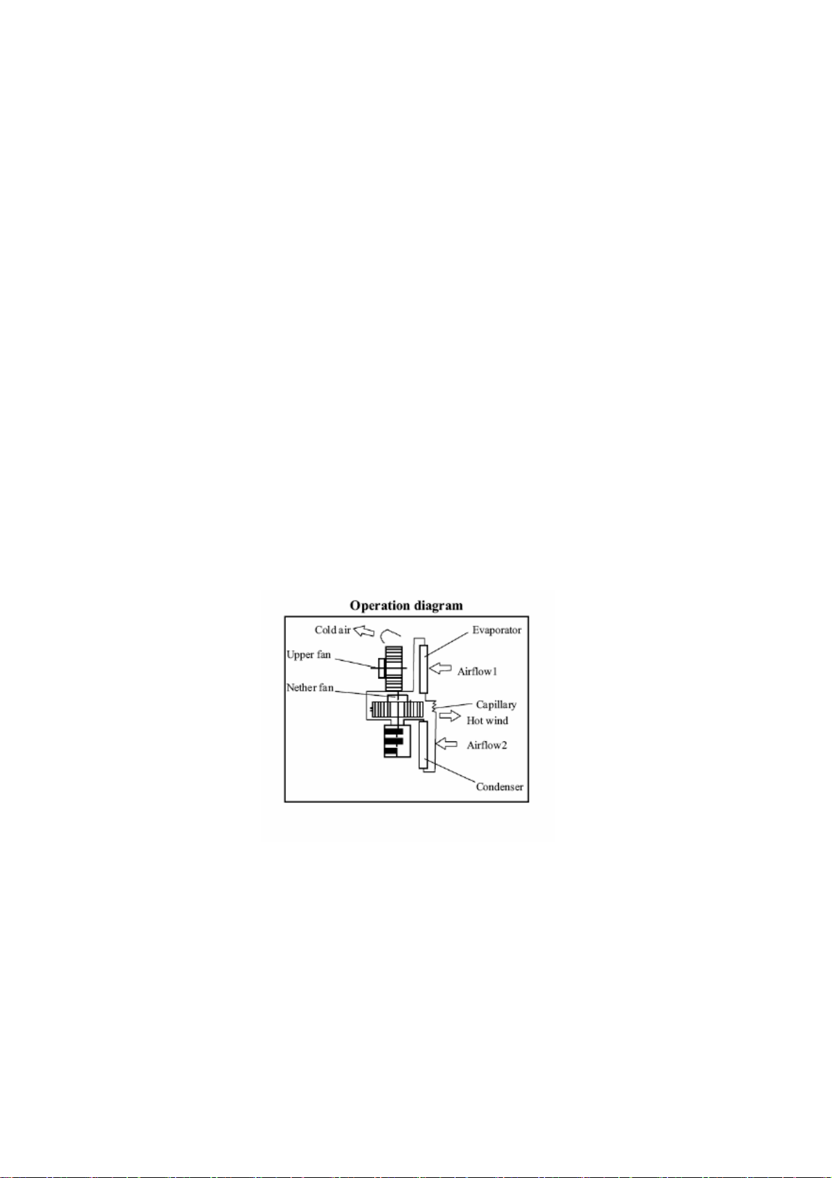
Theory of Operation
The gas has a heat exchange with air in a room and changes into liquid, then passes to a capillary
tube to lower temperature and pressure and enters into the evaporator. With heat exchange,
refrigerant absorbs heat to lower the temperature. The evaporator is lower than th e d ew point
temperature of air in the room; water vapor will condense on the outside surface of the
evaporator and drop down into the drain tank. This cycle lowers the relative humidity in the room
and attains the goal of dehumidification.
Introduction
3
Page 4

Technical Sp ecificatio ns
Model MAC12 MCH12/7
EER Rating Btu/w 8.8 8.8
Cooling Capacity 12,000BTU 12,000BTU
Heating Capacity N/A 7,000BTU
Rated Voltage 115Vac 115Vac
Rated Frequency 60Hz 60Hz
Rated Current 14.6Amps 14.6Amps
Power Input 1200W 1200W cooling/1500W heating
Rated Input 1500W 1500W
Cycling Airflow 174 CFM 174CFM
Refrigerant/R22 1.21LBS 1.21LBS
Noise Max. 62db(A) 62db(A)
Net WT/Gross WT 99/105.6LBS 99/105.6LBS
Unit Dimensions 17.7x14.5 x33.7 17.7x14.5 x33.7
Dehumidifying Volume 13.9 Gallons/day 13.9 Gallons/day
BRK Size 20A 20A
NOTE:
The cooling capacity indicated is measured at ambient temperature DB 86ºF, WB 77.9ºF (inside
and outside equal).
The heating capacity indicated is measured at ambient temperature D B 68
and outside equal).
The Noise level is taken at a distance of 39” from the front part of the appliance in cooling mode.
The power consumption of the fan is measured with the fan at maximum speed.
The specifications indicated only serve as a reference. Please refer to the informatio n contained
on the appliance data plate.
4
º
F, WB 53.6ºF (inside
Page 5
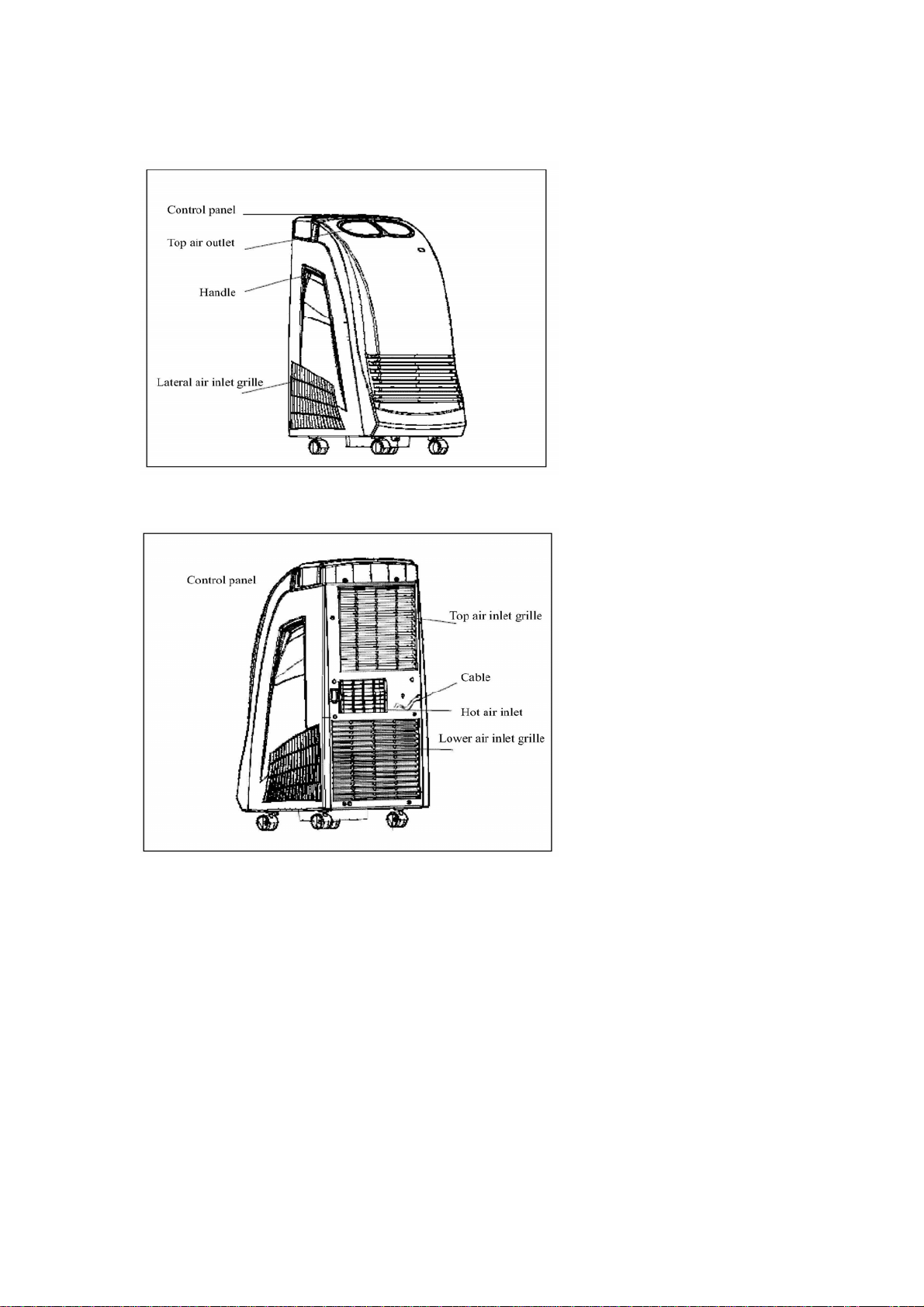
Front
Back
STRUCTURE
5
Page 6
OPERATION
ATTENTION:
DEHUMIDIFYING AND COOLING OPERATION
The operating ranges for cooling and dehumidifying operation is 62ºF - 95ºF.
LOCATION:
Put the mobile air conditioner at an open place where the air outlets cannot be covered up. Place
the unit no less than 20 inches away from a wall or other obstacle.
POWER SUPPLY:
Before connecting the air conditioner to the power supply, please check:
The power supply is rated voltage 115V +- 6%.
The power supply line is PROPERLY grounded and sized for a pickup current of 20A, so as to
avoid voltage drops when starting the air conditioner.
The unit is connected to a 16Amp socket by a 16Amp plug. The wire size should be 10AWG.
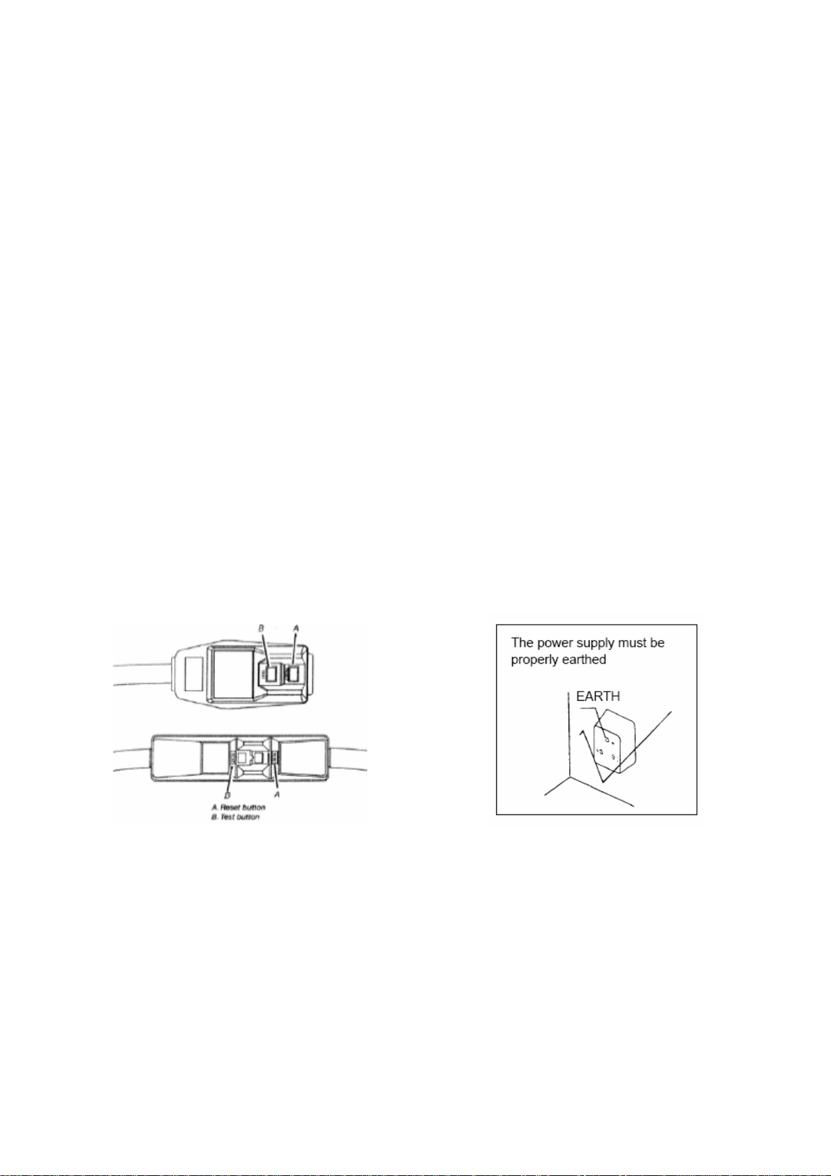
This room air conditioner is equipped with a power supply cord required by UL. This
power supply cord contains state-of-the-art electronics that sense leakage current. If
the cord is crushed, the electronics detect leakage current and power will be
disconnected in a fraction of a second.
please replace it with a special power supply cord by a qualified electrician.
If the power supply cord of the unit is damaged,
NOTE: Your unit’s device may differ from the ones shown.
6
Page 7

OPERATION
In order to prevent power fluctuations during the start of the compressor, the following
installation conditions apply:
1. The power source must be capable of handling 16A continuous.
2. Avoid connecting other equipment to this power source.
3. For power details of the air conditioner, refer to the rating plate of the product.
7
Page 8
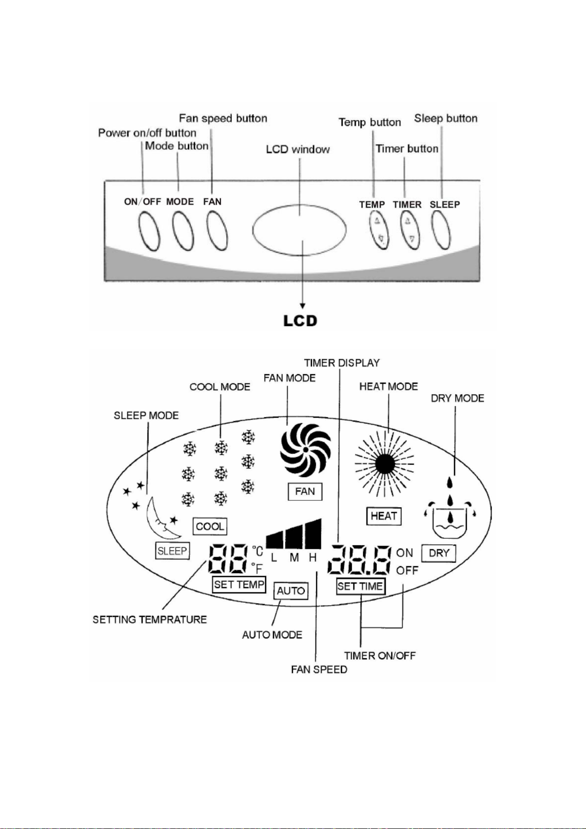
CONTROL PANEL AND LCD
OPERATION
8
Page 9

OPERATION
CONTROL PANEL – BUTTONS
TURN THE AIR CONDITIONER ON:
Press the power ON/OFF button. This will turn the unit on.
MODE BUTTON “MODE”: There are 5 running modes to choose from:
FAN ⇒ COOL ⇒ DRY ⇒ HEAT ⇒ AUTO
NOTE: Only Model MCH12/7 has the heat function.
FAN SPEED BUTTON:
There are three fan speeds in all modes of operation. Push the “FAN” button to change the fan
speed. It will change in the sequence:
HIGH ⇒ MEDIUM ⇒ LOW.
TEMPERATURE SETTING BUTTON “TEMP”:
As soon as the air conditioner has been switched on, the display on the control panel will show
the temperature set point.
Use keys “▲”or“▼” to increase or decrease the temperature setting. It is good practice to set
the temperature before selecting the operational mode.
USE THE “TIMER” BUTTON TO PROGRAM THE AIR CONDITIONER:
Use the “▲” or “▼” buttons to change the time for the air conditioner to turn on or off. When
the unit is running, set the unit stop time; and when the unit is off (but with power connected), set
the start time.
SLEEP BUTTON:
When the unit is running press the “SLEEP” button to activate the sleep mode.
Press once more to deactivate the sleep mode. This key does not function under the “AUTO”
mode.
9
Page 10

OPERATION
COOLING OPERATION
Ensure that the drain tank is properly placed in the unit.
Install the exhaust duct properly (see air exhaust duct page).
During the cooling operation, always place the duct through an open window, or outside of the
area being cooled.
Repeatedly press the “MODE” button to choose the cooling mode.
The LCD Window will indicate “COOL”.
To set the temperature, press the “▲” or “▼” temperature buttons to set the room
temperature between 61º F and 86º F.
Press the “FAN” button to select the fan speed, HIGH ⇒ MEDIUM ⇒ LOW
Note: In order to improve the cooling efficiency:
Ensure that the unit is not exposed to direct sunlight.
Do not place the unit near a heat source.
DEHUMIDIFYING OPERATION
Keep windows and doors closed to aid in effectively dehumidifying the room.
Repeatedly press the “MODE” button to choose the dehumidifying mode.
The LCD Window will display “DRY”. The fan speed is not adjustable in the dehumidifying mode.
When used as a dehumidifier only, do not use the air exhaust duct.
FAN SPEED
Press the “MODE” button to select the fan mode.
The LCD Window will display “FAN”.
Press “FAN” button to choose the fan speed: HIGH ⇒ MEDIUM ⇒ LOW.
HEATING OPERATION (ONLY FOR MODEL MCH12/7)
Press the “MODE” button to select the heating mode.
The LCD Window will display “HEAT”.
Press “FAN” to choose the fan speed: HIGH ⇒ MEDIUM ⇒ LOW.
Note: During heating, only the heat element and blow er fan is activated.
10
Page 11
OPERATION
WATER DRAINAGE
When operating the air conditioner in cooling or dehumidifying mode under normal conditions,
the condensation water is automatically evaporated from an internal drip pan out through the
exhaust duct. Under extremely high humidity conditions, the water in the drip pan may reach a
level that triggers a shut-off mechanism. The compressor and fan will turn off and th e water must
be drained via one of the following two methods.
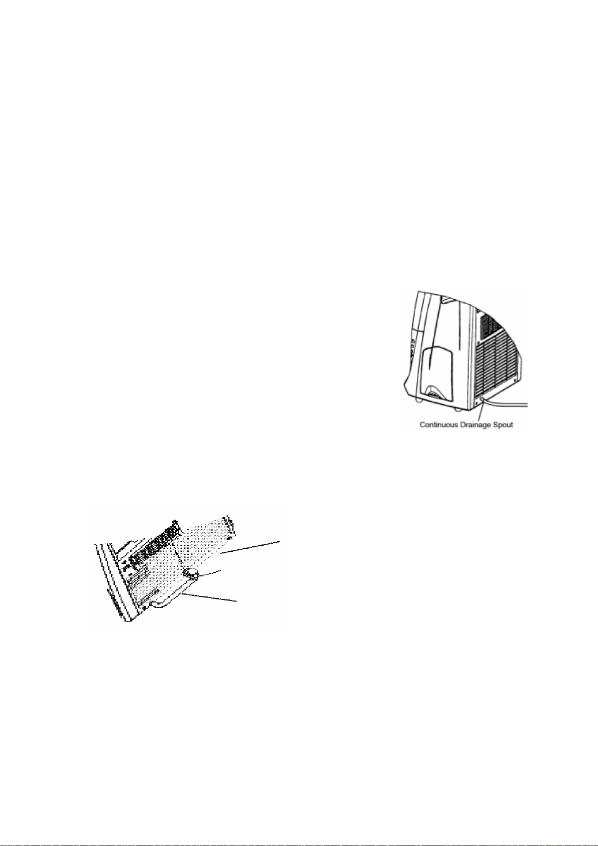
CONTINUOUS DRAINAGE
When the unit is operating on continuous drainage mode, excess condensatio n in the drip pan is
discharged by gravity through the drainage tube to either an external tank (not provided) or to a
condensation water pump device (Optional Item). When the unit is operating on continuous
drainage mode, it can operate continuously regardless of humidity level.
Installation Steps:
Remove the plug from the drainage spout.
Connect the drainage tubing to the drainage spout.
Place the other end of the drainage tube into either an external water
tank or the inlet side of a condensation water pump.
MANUAL DRAINAGE
When the unit is operating in manual drainage mode, excess
condensation in the drip pan will rise until it reaches a predetermined level, at which time the air
conditioner will signal a warning (E4 on LCD) and shut off. To drain the excess condensation, turn
off the conditioner, remove the drain plug and allow water to drip into an external p an or draina ge
tubing.
Back board
Drain pipe clamp
Drain Pipe
Warning: Do not operate the air conditioner without the drain plug unless the drainage tube is
directed to an external drain or bucker. Dripping water may damage wood floor and carpet and
may also cause injury if not properly contained.
11
Page 12
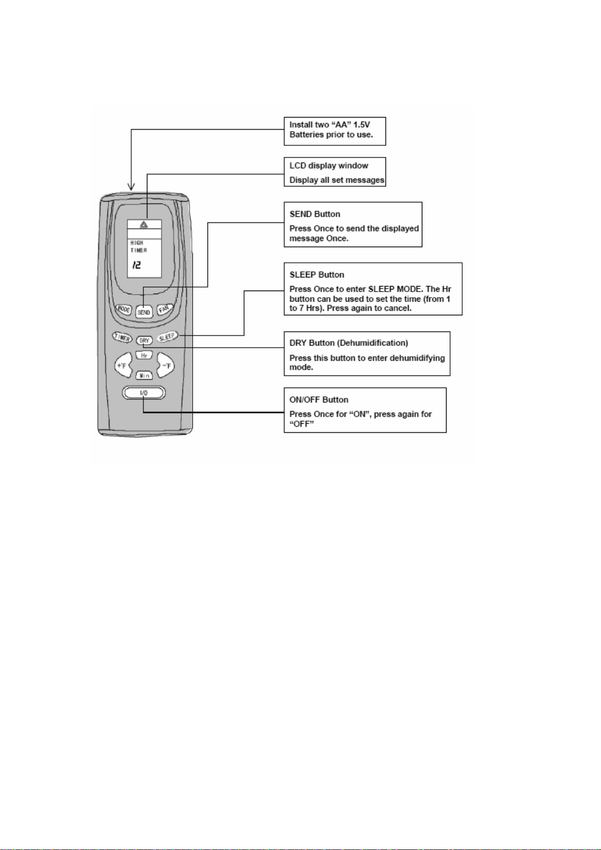
REMOTE CONTROL DESCRIPTION
OPERATION
:
NOTE
Please point the remote control at the signal receiver on the unit panel.
The information displayed can be transmitted at the mode AUTO, ON/OFF, SLEEP, SWING, and
TRANSMIT. The other buttons can only change the messages which should be transmitted within
15 seconds; otherwise the messages will be canceled.
12
Page 13
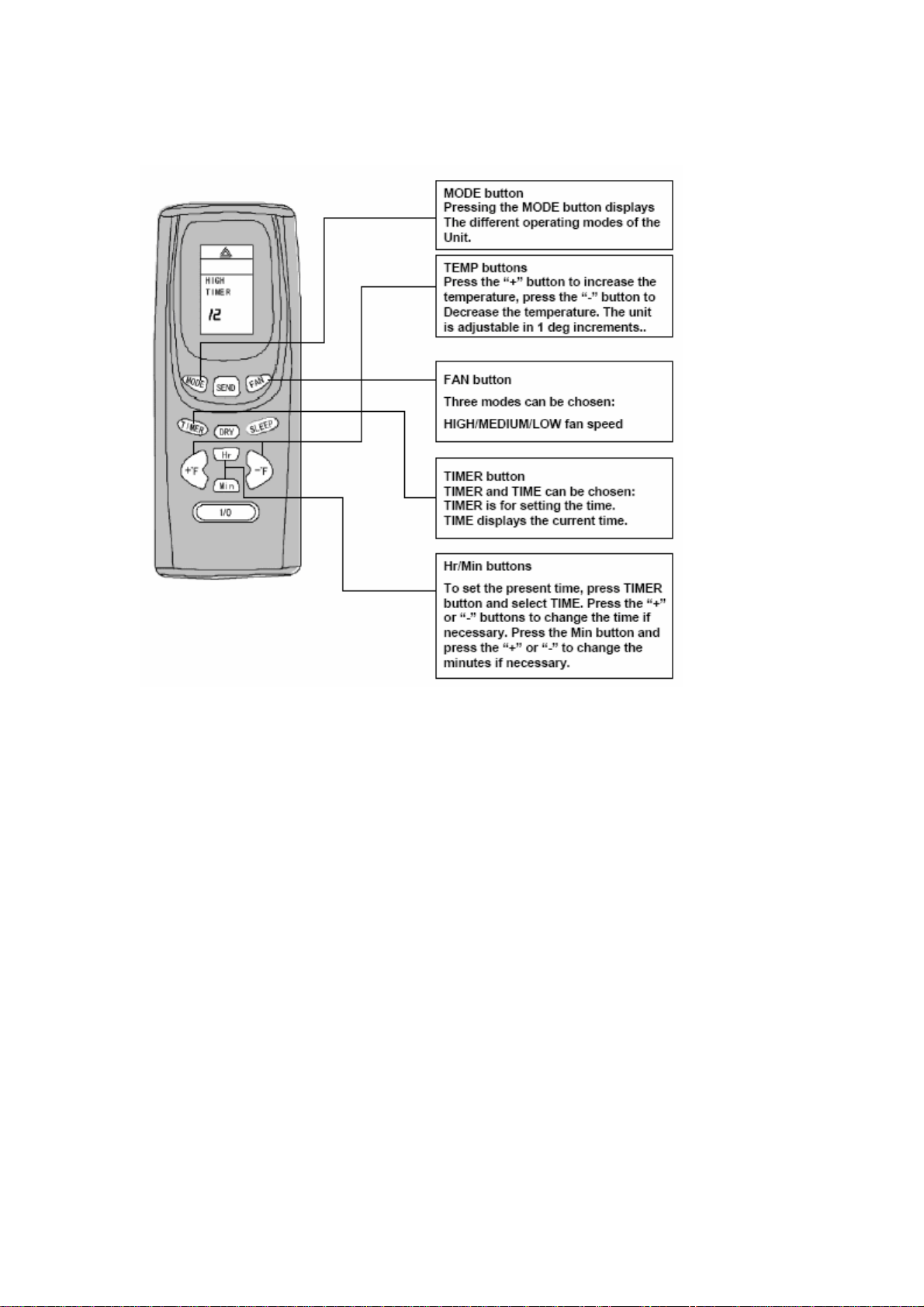
MAIN BUTTONS AND FUNCTIONS
OPERATION
NOTE:
If the power fails, disconnect and reconnect the power cable.
Press the send button on the wireless remote control to restart the unit.
13
Page 14
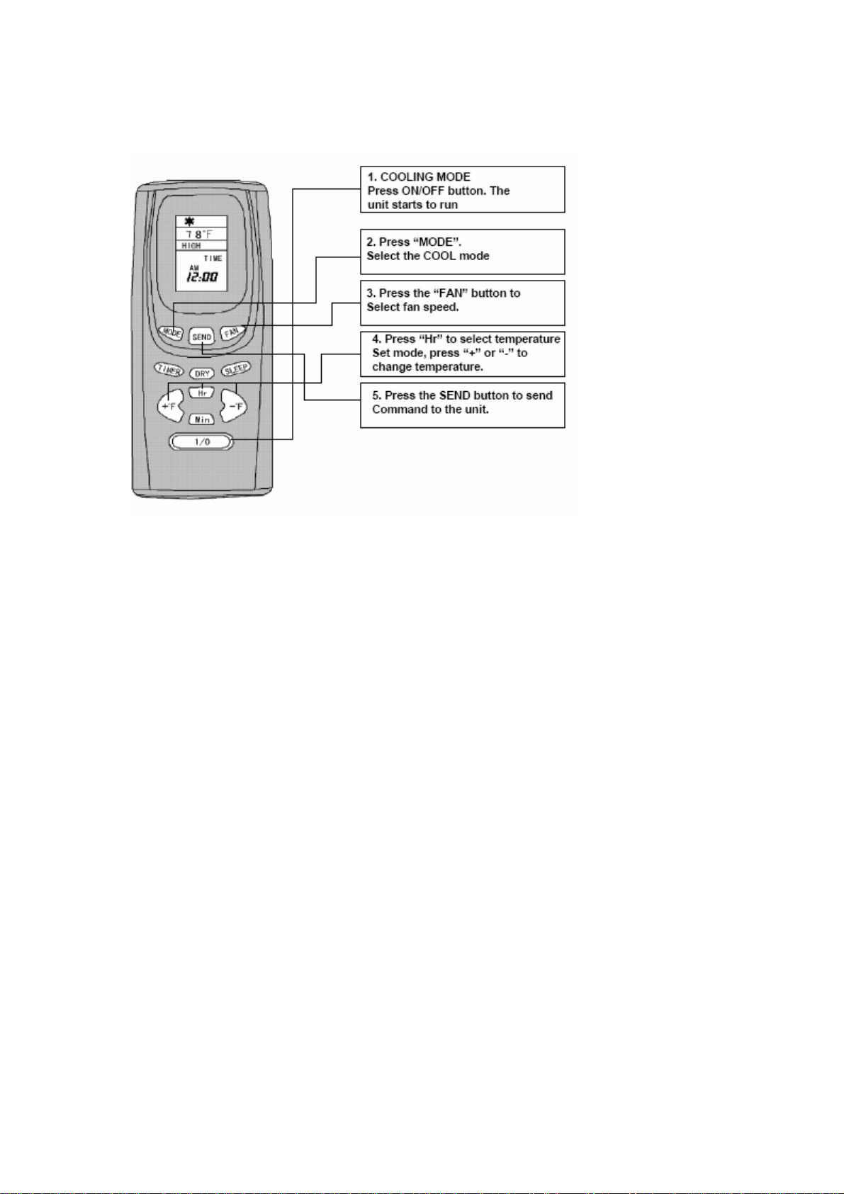
COOLING MODE
OPERATION
14
Page 15
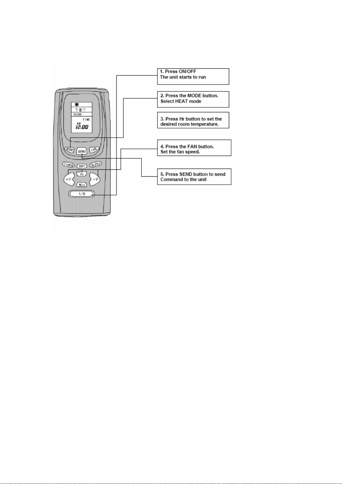
OPERATION
HEATING MODE (ONLY FOR MODEL MCH12/7)
NOTE:
In the heat mode, only the heating element and the blower will operate.
15
Page 16
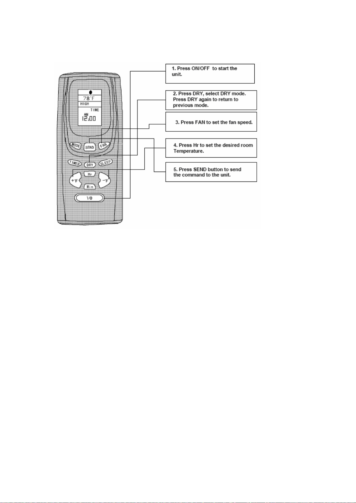
DEHUMIDIFYING (DRY MODE)
OPERATOIN
NOTE:
The compressor is running and the upper fan is running in low speed.
16
Page 17
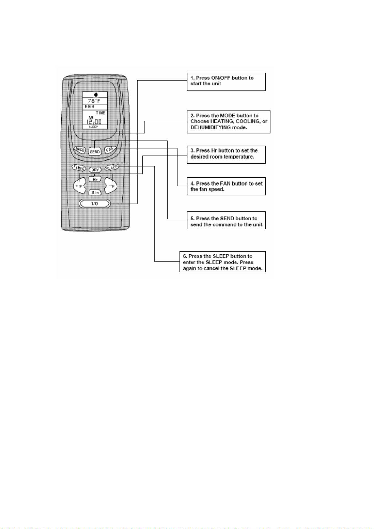
SLEEP MODE
OPERATION
NOTE:
To set the timer in the sleep mode, press the Hr button to select TIMER (displayed on LCD), press
the + or – to select hours.
In the sleep mode, the fan will go to low speed and the temperature will automatically adjust
during the selected hours providing a comfort temperature for sleeping.
17
Page 18
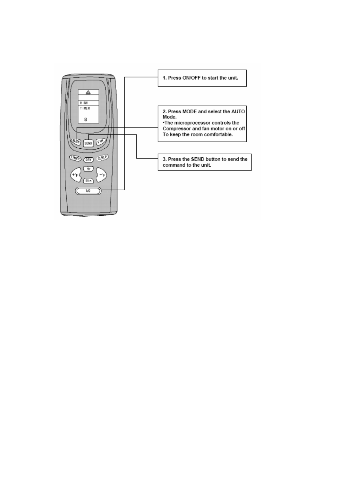
AUTO MO DE
OPERATION
18
Page 19
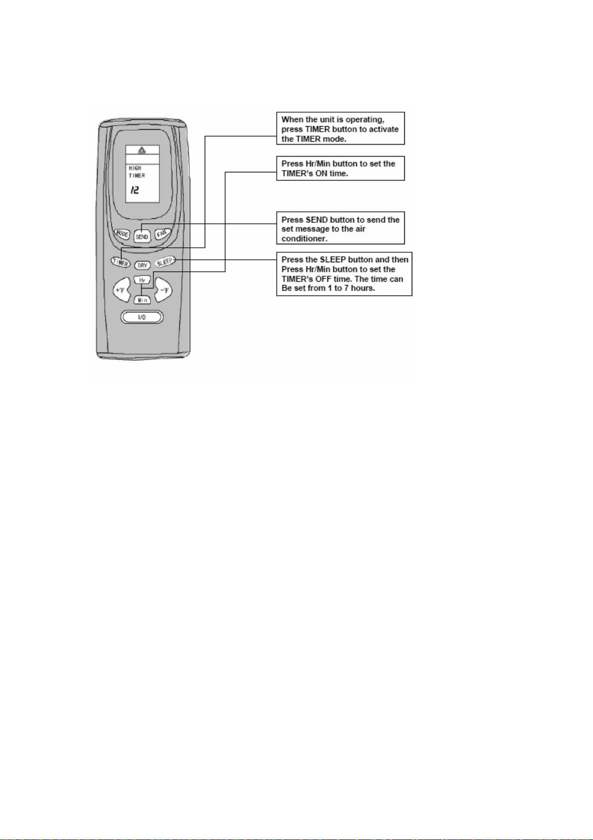
TIMER SETTING
OPERATION
NOTE:
When Timer is set, the air conditioner will turn off immediately.
When the set time is reached, the unit will turn on again satisfying the ro om temperature.
During the timer setting, the timer can be reset by pressing TIMER and pressing the + or – button.
Pressing the SLEEP button cancels the timer mode, and pressing the TIMER button will cancel
the sleep mode. Both can not be set simultaneously.
19
Page 20
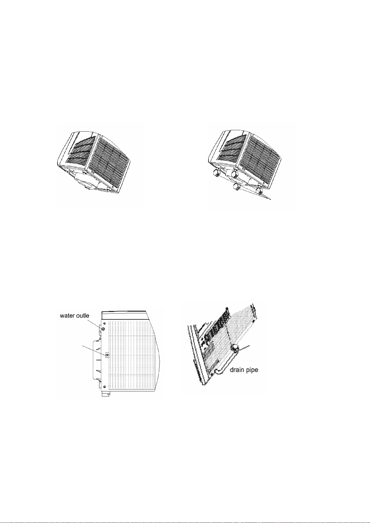
ACCESSORIES INSTALLATION
1. Caster Installation:
Note: The casters must be assembled before using the unit. Tilt the unit minimally to install the
casters.
1. Open the accessory box and remove the casters (4).
2. Lift up the unit horizontally 4 to 8” above the ground.
3. Fit the caster into the opening in the base. (See diagrams).
tilt angle
2. Assemble drain pipe
The unit must have the drain pipe assembled properly before using. If not, the water will drain
outside the tank causing a potential hazard.
1) Remove the drain pipe, plug, and clamp from the packing box.
2) Remove the plug and attach the pipe securely to the water outlet on the base.
3) Attach the pipe to the clamp on the back board of the unit.
Clamp
Casters
backside
Attach the pipe
To the clamp
20
Page 21
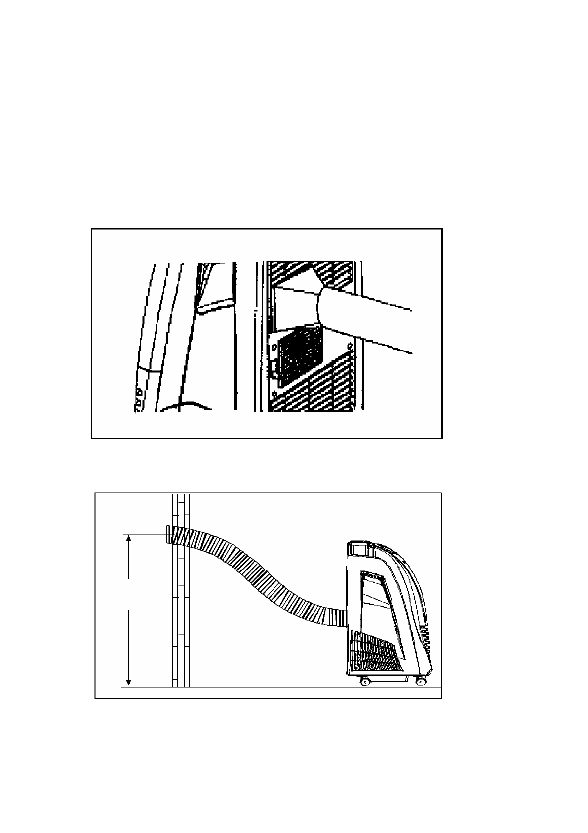
3. Air exhaust duct
THE AIR EXHAUST DUCT MOUNTING MENTOD CAUTION
Fix the square end of the exhaust duct to the exhaust terminal of the unit.
Put the other end (discharge) to the nearest window.
ATTENTION:
The length of the air exhaust must be between 19”-78”
When mounting, try to keep the air exhaust duct horizontal.
Correct mounting shown below. (If mounting in the wall, the height of the hole should be 15”-51”
above the floor)
21
Page 22
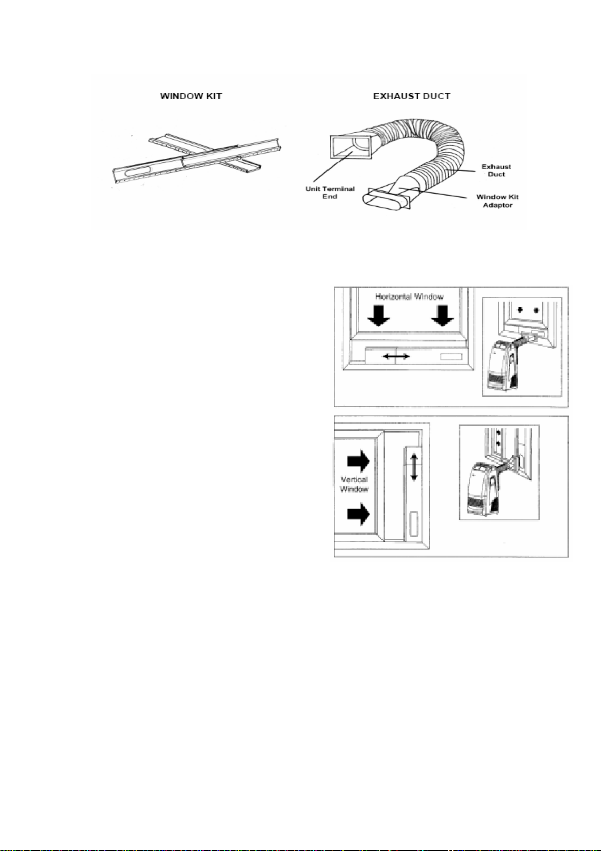
WINDOW KIT INSTALL ATION
Open window or sliding door approximately 5 inches (13 cm). Adjust the length of the window kit
to the same length of the window or sliding door. Use
two or three panels if necessary and secure panels
into place by fastening the 3/4” Phillips head screws
into the pre-drilled panel holes.
Alternatively you may need to mark a single panel
and cut it down to properly fit the window opening.
The window kit (three panels) has a maximum length
81 inches.
Place the window kit between the window and the
window frame as shown in the picture to the right.
Close the window onto the window kit to form a tigh t
seal.
Attach the exhaust duct window kit adapter to the
window kit. Tabs located on the adapter will lock into
place securing the adapter to the window kit.
NOTE:
Using the window kit will cause the window not to be properly closed and locked. Consider taking
additional security measurements.
22
Page 23
MAINTENANCE
WARNING
We recommend you follow the cleaning and maintenance operations regularly as indicated in the
instructions. Unplug the unit before performing any cleaning operations to prevent accidents
caused by electrical shock.
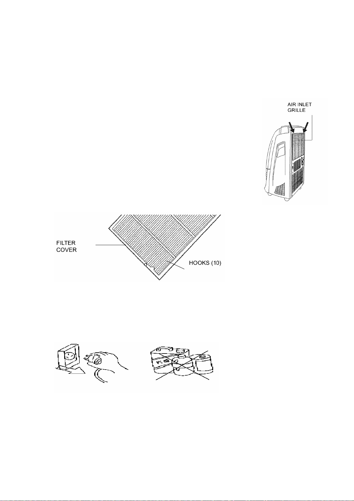
AIR FILTER
If the air filter is clogged with dust the air flow volume is reduced.
For this reason, clean the filter regularly.
To remove the air filter, lift up the filter cover and pull the air filter out from the
cover.
Once the filter is dry, hook the filter onto its cover using the fastening hooks on
the inside of the cover. Place the hooks on the front into the holes on the
structure itself and push it back into place.
AIR CONDITIONING UNIT SURFACES
Clean the surfaces of the air conditioning unit with a damp cloth and dry it with a dust cloth.
WARNING:
KEEP AWAY FROM FLAMMABLE FLIUIDS OR SUBSTANCES!
23
Page 24
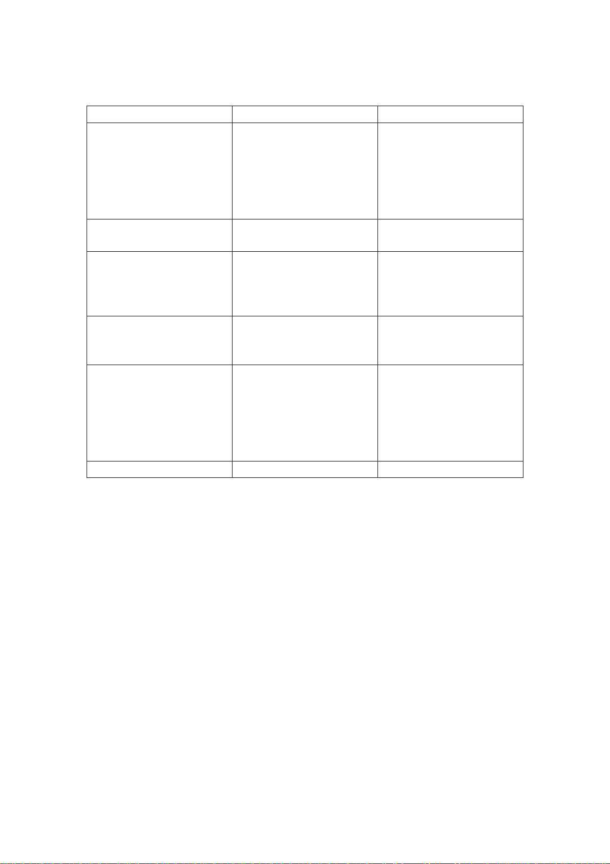
TROUBLE SHOOTING
BEFORE CALLING FOR REPARI SE RVICE, PLEASE CHECK:
PROBLEM CAUSE SUGGESTED SOLUTION
The air conditioner does not
work
The indicator is in the run
mode but unit is not running.
Cooling mode selected, unit
not operating.
In dehumidify mode, no cool
air is coming out of the unit.
LCD window indicates “E1” Power interruption
LCD window indicates “E4” The water tank is full. Drain the water.
Not plugged in
Defective plug or socket
Fuse blown
Breaker tripped
The timer may be activated Reset the timer or allow timer
Room temperature is below
the temperature setting.
There is frost on the
evaporator.
Remove the air filter and
observe if frost is on the
evaporator.
Defective unit.
24
Plug in correctly .
Change the plug or socket
Replace fuse
Reset Breaker
If problem persists, contact a
licensed technician.
to time out.
Normal Operation
The unit is defrosting. It will
run after defrosting is
finished.
The unit is defrosting. It will
run after defrosting is
finished.
Turn unit off, disconnect from
power source. Wait 10
minutes, reconnect and turn
on again. If error code appears
again, the unit needs to be
serviced.
Page 25

SAFETY CAUTIONS AND SPECIAL GUIDELINES
WARNING
Avoid direct sunlight as surface discoloration may occur
Do not use the unit near water to avoid el ectrical shock.
Do not use near gas appliances, fires, or near flammable liquids.
Do not use the unit in the immediate vicinity of a bath, shower, or a swimming pool.
OTHER
Keep the unit 3” away from TV sets or radios to avoid the risk of electromagnetic interference.
Do not use the unit with the air outlet close to walls.
Do not cover the air outlet.
SERIOUS CAUTION
If the unit tilts over or falls and does not operate, contact your local dealer.
Do not spray with insecticide or other chemicals as the plastic case may be deformed.
SPECIAL GUIDE
This unit is a mobile air conditioner/heater, and unlike a window unit, is self contained and
located within the interior of the room. For this reason, it must be exhausted properly, and
depending upon the room conditions, will always cool locally.
25
Page 26

WARRANTY
The portable air conditioning system you have purchased carries a limited warranty of one (1)
year on parts and five (5) years on the compressor. Labor is not covered under warranty.
Please contact your local dealer for additional details.
INTERNATIONAL REFRIGERATION PRODUCTS INC.
11325 Nations Ford Road, Suite N, Pineville, NC 28134-8393
Tel: (704)-504-8590
Fax: (704)-504-3023
950-0030
26
 Loading...