

Page 1
©20 14 The rma lta ke Tech nol ogy Co., L td. All Rights Reser ved . 2 014 .01
All other r egis tered t rademar ks bel ong to their re specti ve comp anies.
Tested To C omply
With F CC Standa rds
FOR H OME OR O FFICE USE
www. therm altak e.com
Si m pl e , Ye t E le g an t
User's Man ual
Benutzer handbuc h
Mode d’emp loi
Manual del u suario
Manuale de ll’uten te
Manual do Ut ilizado r
安裝說明書
用戶手冊
ユーザーズマニュ アル
Руководс тво польз ователя
kullanıcı elk itabı
(EEE Yönet meliğin e Uygundu r)
คู่มือการใช้
Page 2
Specific ati o n
Co ntents
Chapter 1. Product Introduction
Sp eci f ica tio n
1.0
1.1
Ac ces s ory
1.2
War n ing a nd No t ice
02
02
03
Cas e Type
Dim ensio n (H*W* D) 585 x 2 35 x 602 mm ( 23 x 9.3 x 23 .7 inch )
Net W eight
Sid e Panel
Col or
Mat erial
Coo ling Sy stem
Chapter 2. Installation Guide
Si de Pa nel D isa s sem bly
2.0
2.1
Mo the r boa rd In s tal lat i on
2.2
PS U Ins t all ati o n
5. 25" D e vic e Ins t all ati o n
2.3
Ex ter n al 3. 5” De v ice I nst a lla tio n
2.4
3. 5” & 2. 5 ” HD D I nst a ll a tio n
2.5
HD D Cag e I nst all a tio n
2.6
PC I Car d I nst all a tio n
2.7
Keyb oar d & M ous e Sec u rit y Loc k U sag e
2.8
Fan S p eed C ont r ol Op era tio n
2.9
Ai r Coo l ing I nst a lla tio n
2.10
Li qui d C ool ing I n sta lla t ion
2.11
Chapter 3. Leads Installation
Ca se LED Con n ect ion
3.0
US B Con nec t ion 2.0
3.1
US B Con nec t ion 3.0
3.2
Au dio Conn e cti on
3.3
Chapter 4. Other
Th erm a lta ke Powe r S upp ly Se r ies ( Opt i ona l)
4.0
1 2
05
07
08
09
11
12
13
14
15
16
17
18
19-2 4
19-2 4
19-2 4
19-2 4
25
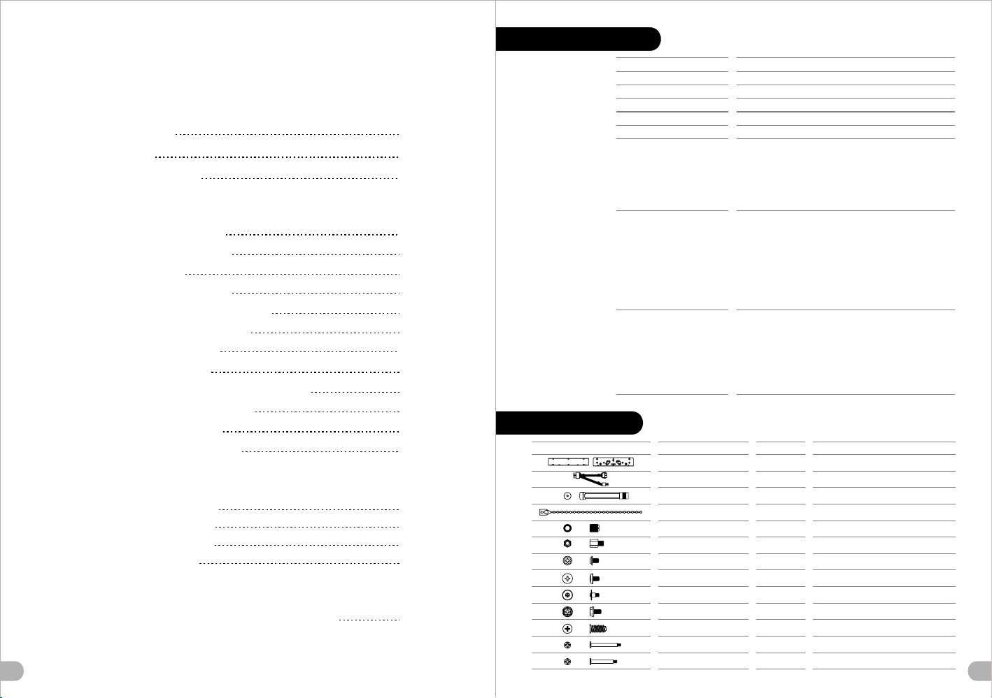
Accessor y
Fig ure
Fan S uppor t
Rad iator S uppor t
Par ts Na me
5.2 5" To 3.5 " Brack et
8 Pin C PU Exte nd Cabl e
Buz zer
Cab le Tie
Nut S etter
Sta nd-of f #6-32 *6.0m m
Scr ew M3*5 mm
Scr e # 6-32* 5.0mmw
Scr e # 6-32* 4.0mmw
Scr e # 6-32* 6.0mmw
Scr ew Ø5*1 0mm
Scr ew #6-3 2*33m m
Scr ew #6-3 2*29m m
Ful l Tower
9.8 Kg / 21.7 l b
Tran spare nt Wind ow
Ext erior & I nteri or : Blac k
SEC C
Fro nt (int ake) :
200 x 2 00 x 30 mm fa n x 2
(60 0~800 rpm, 13 ~15dB A)
Rea r (exha ust) :
140 x 1 40 x 25 mm Tur bo fan x 1
(10 00rpm , 16dBA )
Top (e xhaus t) :
200 x 2 00 x 30 mm fa n x 1
(60 0~800 rpm, 13 ~15dB A)
Fro nt :
1 x 120 mm or 2 x 120 mm or 3 x 120 mm
1 x 140 mm or 2 x 140 mm
1 x 200 mm or 2 x 200 mm
Top :
1 x 120 mm or 2 x 120 mm or 3 x 120 mm
1 x 140 mm or 2 x 140 mm
1 x 200 mm or 2 x 200 mm
Rea r :
1 x 120 mm or 1 x 140 mm
Bot tom :
1 x 120 mm or 2 x 120 mm
1 x 140 mm or 2 x 140 mm
Fro nt :
1 x 120 mm or 1 x 240 mm or 1 x 360 mm
1 x 140 mm or 1 x 280 mm or 1 x 420 mm
Top :
1 x 120 mm or 1 x 240 mm or 1 x 360 mm
1 x 140 mm or 1 x 280 mm or 1 x 420 mm
Rea r :
1 x 120 mm or 1 x 140 mm
Bot tom :
1 x 120 mm or 1 x 240 mm
1 x 140 mm or 2 x 280 mm
Q't y
2
1
1
5
1
3
32
26
32
4
8
4
12
Use d for
For F DD/3. 5"HDD
For P ower Su pply wi th Moth erboa rd
For M other board A larm
For S ettle C able
For M other board I nstal latio n
For M other board
For O DD/FD D/2.5 "HDD/ Radia tor
For M other board /3.5" HDD/R adiat or
For 3 .5"HD D(HDD T ray)
For P ower Su pply
For B ottom F an
For T op Fan
For T op Fan/ Front F an
Page 3
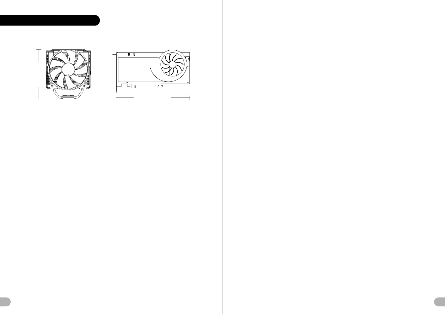
Warnin g a nd No tic e
CPU Cooler Height Limitation VGA (A dd - on c ar d) L en gt h Li mi ta ti on
<1 80 m m
<3 60 m m
Warning! !
- Heigh t li mi t fo r th e CP U he at sink:
The h ei gh t li mi t fo r th e CP U he atsink is 180 mm (7.1 inches) .
- Lengt h li mi t fo r th e VG A (g ra phics card):
The l en gt h li mi t fo r th e VG A (g raphics card) is 360 mm (14.2 i nc he s) .
Warnung! !
- Höhen be sc hr än ku ng f ür C PU-Kühler:
Die Höh en be sc hr än ku ng f ür den CPU-Kühler liegt bei 180 m m (7 .1 Z ol l) .
- Länge nb es ch rä nk un g fü r die VGA (Grafikkarte):
Die Län ge nb es ch rä nk un g für die VGA (Grafikkarte) b et rä gt 3 60 m m (1 4. 2 Zo ll ).
Avertiss ement !
- Haute ur l im it e du d is si pa teur thermique du processeu r :
La haut eu r li mi te d u di ss ip ateur thermique du processe ur e st d e 18 0 mm ( 7. 1 po uc es).
- Longu eu r li mi te d e la c ar te V GA (carte graphique) :
La long ue ur l im it e de l a ca rt e VGA (carte graphique) est d e 36 0 mm ( 14 .2 p ou ce s) .
Precauci ón
- Lím it e de a lt ur a pa ra e l di si pador de calor de la CPU:
El lí mi te d e al tu ra p ar a el d is ipador de calor de la CPU es de 180 mm (7 .1 p ul ga da s) .
- Lím it e de l on gi tu d pa ra l a ta rjeta gráfica (VGA):
El lí mi te d e lo ng it ud p ar a la t arjeta gráfica (VGA) en de 36 0 mm ( 14 .2 p ul ga da s) .
Atenção! !
- Limit e de a lt ur a pa ra o d is si pador do CPU:
O lim it e de a lt ur a pa ra o d is si pador do CPU é 180 mm (7.1 polega da s) .
- Limit e de c om pr im en to p ar a VGA (placa gráfica):
O lim it e de c om pr im en to p ar a VGA (placa gráfica) é 360 mm (1 4. 2 po le ga da s) .
警告!!
- CPU散熱器 的高 度限 制:
CPU散熱器 的高 度限 制為1 80 mm ( 7 .1英 吋 )。
- VGA (顯示 卡)的長 度限 制:
VGA (顯示 卡)的長 度限 制為3 60 mm ( 14 .2英 吋 )。
警告!!
- CPU散热器 的高 度限 制:
CPU散热器 的高 度限 制为1 80 mm(7 .1英 寸) 。
- VGA( 显卡 )的 长度 限制 :
VGA( 显卡 )的 长度 限制 为36 0m m(14 .2英 寸)。
警告
- CPUヒート シン クの 高さ 制限:
CPUヒート シン クの 高さ 制限 は18 0 mmで す。
- VGA( グラ フィ ック スカ ード )の 長さ 制限:
VGA( グラ フィ ック スカ ード )の 長さ 制限 は360 mmです。
Внимание!
- Огр ан ич ен ие п о вы со те д ля р адиатора ЦП.
Огр ан ич ен ие п о вы со те д ля р адиатора ЦП составляет 18 0 мм ( 7. 1 дю йм а).
- Огр ан ич ен ие п о дл ин е дл я пл аты VGA (графическая плата) .
Огр ан ич ен ие п о дл ин е дл я пл аты VGA (графическая пла та) состав ля ет 3 60 м м
(14 .2 д юй ма) .
Uyarı! !
- CPU ısı alıcısı iç in y ük se kl ik sınırı:
CPU ısı a lıcısı iç in y ük se kl ik sınırı 1 80 m m’ dir (7.1 inç).
- VGA ( gr af ik k ar tı) iç in u zu nl uk sınırı:
VGA ( gr af ik k ar tı) iç in u zu nl uk sınırı 3 60 mm’dir (14.2 inç).
Attenzio ne!
- Limit e di a lt ez za p er i l di ss ipatore di calore della CPU:
Il li mi te d i al te zz a pe r il d is sipatore di calore della CPU è 18 0 mm ( 7. 1” ).
- Limit e di l un gh ez za p er l a VG A (schede grafiche):
Il li mi te d i lu ng he zz a pe r la V GA (scheda grafica) è 360 mm (1 4. 2" ).
คำเตือน!!
- ขีด จำ กัดความสูงสำหรับฮีตซิงก์ของ CPU:
ขีด จำ กัดความสูงสำหรับฮีตซิงก์ของ CPU คือ 180 ม ม. ( 7.1 นิ้ว)
- ขีด จำ กัดความยาวสำหรับ VGA (การ์ดแสดงผล):
ขีด จำ กัดความยาวสำหรับ VGA (การ์ดแสดงผล) คือ 36 0 มม. (14.2 นิ้ว)
3 4
Page 4
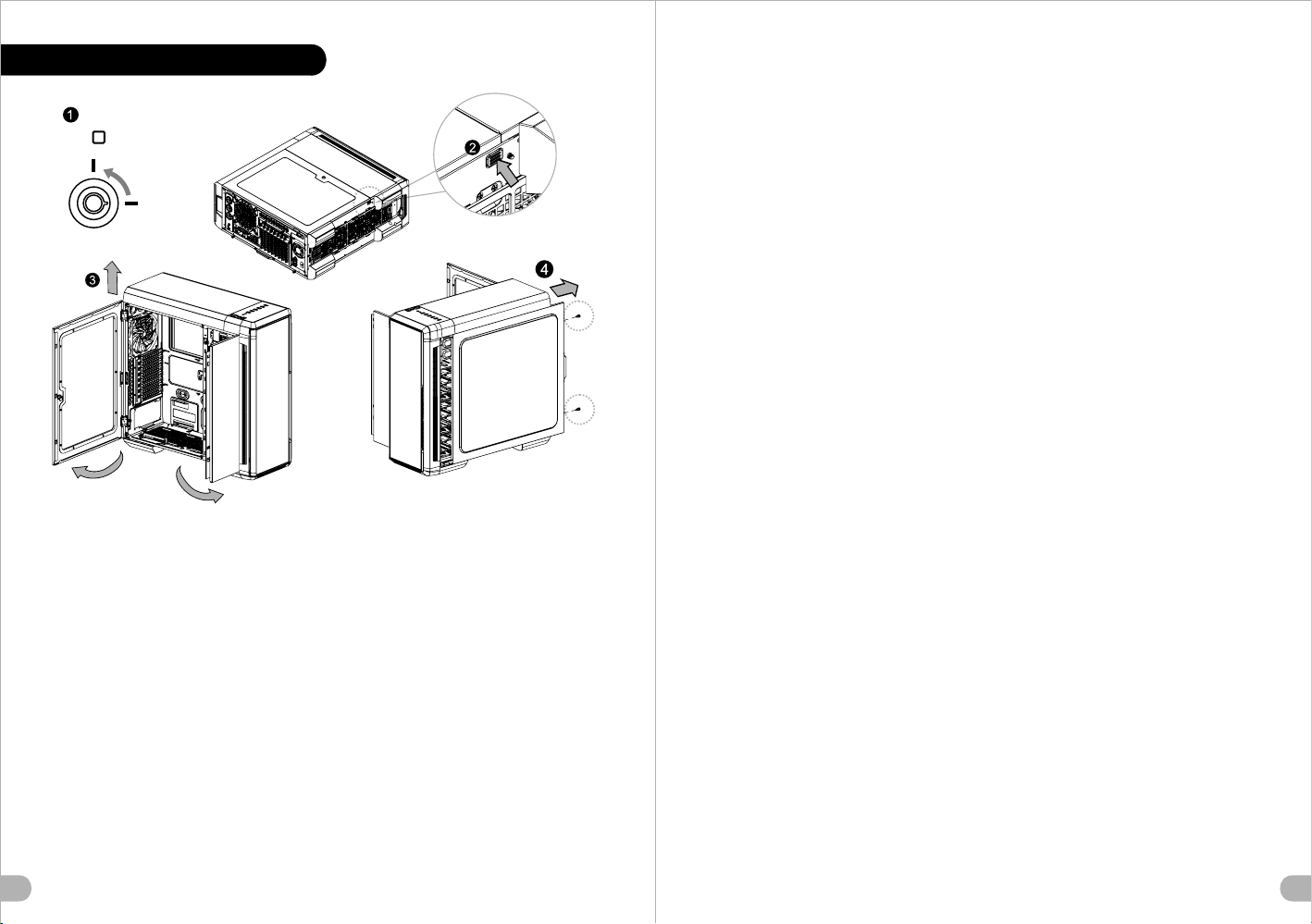
Side Panel Disa s sem bly
Itali ano /
Pannello laterale sinistro
1. Ruotare il foro del pannello laterale in
1
OPEN
LOCK
posizione OPEN (APERTO) utilizzando la
chiave.
2. Tenere premuto il pulsante di rilascio alla
base del case.
3. Ruotare il pannello laterale lontano dal case e
sollevare lateralmente per rimuovere il pannello.
Pannello laterale destro
Rimuovere le viti sulla parte posteriore dello
chassis e aprire il pannello laterale.
Portu guês/
Painel lado esquerdo
1. Rode o orifício do painel lateral para a
posição OPEN (aberto), com a chave.
2. Mantenha premido o botão para abrir na parte
inferior da caixa.
3. Rode o painel lateral, afastando da caixa e
levante para remover o painel.
Painel lado direito
Remova os parafusos na parte de trás da caixa e
abra o painel lateral.
繁體中文 /
左側板
1. 用鑰匙將側板鎖孔轉至OPEN位置。
English /
Left si de panel
1. Turn the keyhole of the side panel into the
OPEN po sition using the key.
2. Push a nd hold the release button on the
botto m of the case.
3.Rotate the side panel away from case and then
lift ve rtically to remove the panel.
Right side panel
Remove the screws on the back of the chassis,
and open the side panel.
Deutsch /
Linke Seitenverkleidung
1. Drehen Sie das Schloss der linken
Verkleidung mithilfe des Schlüssels in die
Position OFFEN
2. Drücken und halten Sie den
Verriegelungsknopf am unteren Rand des
Gehäuses.
3. Drehen Sie die Seitenverkleidung vom
Gehäuse weg und heben Sie sie dann vertikal
an, um si e zu entfernen.
Rechte Seitenverkleidung
Entfe rnen Sie die Schrauben auf der Rückseite
des Gehäuses und öffnen Sie das Seitenteil.
Français /
Panneau latéral gauche
1. Tournez le trou de la serrure du panneau
latéral dans la position OUVERTE en utilisant la
clé.
2. Appuyez sur le bouton de libération au bas du
boîti er et maintenez-le enfoncé.
3. Faites tourner le panneau latéral en l’écartant
du boîtier et ensuite, soulevez-le verticalement
pour l’enlever.
Panneau latéral droit
Enlevez les vis à l’arrière du châssis et ouvrez le
panneau latéral.
Español /
Panel lateral izquierdo
1. Gire e l ojo de la cerradura del panel lateral a
la posición OPEN (ABIERTO) utilizando la llave.
2. Empu je y sostenga el botón de liberación de
la parte inferior de la tapa.
3. Gire e l panel lateral hacia el lado opuesto de
la tapa y, a continuación, levante verticalmente
para quitar el panel.
Panel lateral derecho
Extraiga los tornillos de la parte posterior de la
caja y abra el panel lateral.
2. 按壓機殼底部側板釋放鈕。
3. 轉動並向上抬升至移除左側板。
右側板
移除機殼後方螺絲,將側板打開。
简体中文 /
左侧板
1. 用钥匙将 侧板锁孔转至OPEN位置。
2. 按压机壳 底部侧板释放钮。
3. 转动并向 上抬升至移除左侧板。
右侧板
卸除机壳后 方螺丝,将侧窗打开。
日本語 /
左側のパネ ル
1. かぎを使 用し、側面パネルのかぎ穴を回して
OPEN(開く)位置にします。
2. ケース下 部の解除ボタンを押したままにします。
3. 側面パネ ルをケースから遠ざけるように回転し、
垂直に持ち 上げてパネルを取り外します。
右側のパネ ル
シャーシ背 面のねじを取り外し、サイドパネルを開
きます。
5 6
Русск ий /
Левая б оков ая пан ель
1. С помощью кл юча по верните отверстие
под клю ч на бок овой п анели в положение
OPEN (О ТКРЫ ТО).
2. Нажмите и уд ержи вайте кнопку
освоб ожде ния на н ижней части корпуса.
3. Чтоб ы снят ь боко вую панель, отведите
ее от корпуса и п одни мите в вертикальном
направлен ии.
Правая боко вая па нель
Откру тите винты на задней стенке корпуса
и откро йте боковую панель.
Türkçe /
Sol panel
1. Yan panelin anahtar deliğini, anahtarı
kullanarak AÇIK konumuna getirin.
2. Kasanın altındaki serbest bırakma
düğmesini basılı tutun.
3. Yan paneli kasanın dışına doğru
döndürün ve daha sonra, dik bir şekilde
kaldırarak çıkarın.
Sağ panel
Kasanın arkasındaki vidaları çıkarın ve yan
paneli açın.
ภาษาไทย /
แผงด้านข้างซ้าย
1. ใช้ลูกกุญแจไขรูกุญแจของแผงด้านข้างไปที่ตำแหน่ง
OPEN (เปิด)
2. กดปุ่มปลดล็อคที่ด้านล่างของเคสค้างไว้
3. หมุนแผงด้านข้างออกจากเคส
แล้วยกขึ้นในแนวตั้งเพื่อถอดแผงออก
แผงด้านข้างขวา
ถอดสกรูที่ด้านหลังของแชสซีส ์ แล้วเปิดแผงด้านข้าง
Page 5
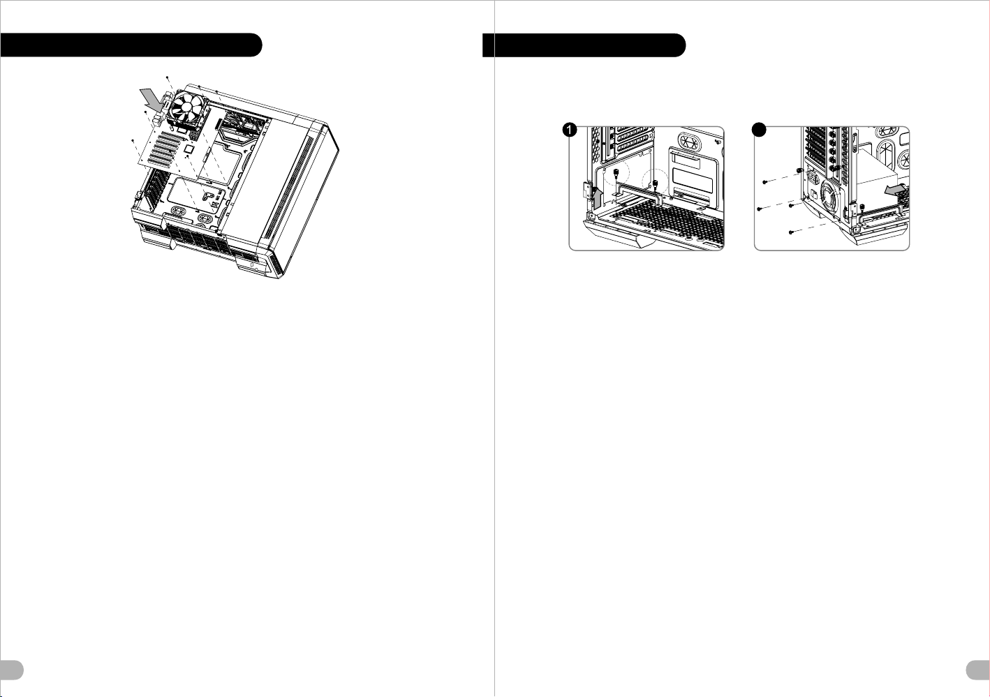
Motherbo ard In sta lla tio n
PSU Instal lat i on
2
English /
1. Lay down the chassis.
2. Install the motherboard in proper location and
secure it with screws.
Deutsch /
1. Legen Sie das Gehäuse auf die Seite.
2. Installieren Sie die Hauptplatine in ihrer
vorgesehenen Position und sichern Sie sie mit
Schrauben.
Français /
1. Pose z à plat le châssis.
2. Installez la carte mère dans l'endroit approprié et
sécurisez-la avec des vis.
Español /
1. Tumb e el chasis.
2. Instale la placa madre en la ubicación adecuada
y asegúrela con tornillos.
Itali ano /
1. Poggiare lo chassis.
2. Installare la scheda madre nella posizione
appro priata e fissarla con le viti.
Portu guês/
1. Deixe a caixa.
2. Instale a motherboard no local adequado e
aparafuse.
繁體中文 /
1. 將機殼平 放。
2. 將主機板 放置在合 適的位置並用零件包中之螺
絲固定。
简体中文 /
1. 放平机箱 。
2. 在合适的 位置安装主板并以螺丝安全固定。
日本語 /
1. シャーシ を下に置 きます。
2. マザーボ ードを適 切な場所 に取り付け、ねじで
固定します 。
Русск ий /
1. Раск ройт е сист емный блок.
2. Уста нови те мат еринскую плату в надлежащее
место и закре пите е е винтами.
Türkçe /
1. Kasayı yan yatırın.
2. Ana kartı uygun konuma takın ve vidalarla
sabitleyin.
ภาษาไทย /
1. วางแชสซีส์นอนลง
2. ติดตั้งเมนบอร์ดในตำแหน่งที่เหมาะสมแล้วขันสก
รูยึดให้แน่น
English /
Place the power supply in proper location and
secure it with screws.
Deutsch /
Installieren Sie das Netzteil an seiner Position und
sichern Sie es mit Schrauben.
Français /
Mette z l'alimentation dans le bon endroit et
sécurisez-la avec des vis.
Español /
Coloque el suministro de alimentación en el lugar
adecuado y asegúrelo con tornillos.
Itali ano /
Posizionare l'alimentatore in modo appropriato e
fissa rlo utilizzando le viti.
Portu guês/
Coloque a fonte de alimentação na devida
localização e aparafuse.
繁體中文 /
將電源供應 器放在正 確的位置,並用螺絲固定
鎖上。
简体中文 /
恰当定位电 源供应器位置并以螺丝安全固定。
日本語 /
電源装置を 適切な場 所に取り 付け、ねじで固
定します。
Русск ий /
Устан овит е блок п итания в надлежащее
место и закре пите е го винтами.
Türkçe /
Güç kay nağını uygun konuma yerleştirin ve
vidalarla sabitleyin.
ภาษาไทย /
วางแหล่งจ่ายไฟในตำแหน่งที่เหมาะสมแล้วขันสกรู
ยึดให้แน่น
7 8
Page 6

5.25" Devi c e Ins tal lat ion
English /
1. Remove the 5.25” drive bay cover.
2. Slide the 5.25” device into the drive bay to lock
the device.
Note: Press the 5.25” tool-free mechanism to
unlock the device.
Deutsch /
1. Entfernen Sie die Abdeckung des 5,25 Zoll
Laufwerksschachts.
2. Schieben Sie the 5,25 Zoll Einheit in den
Laufwerksschacht, um die Einheit zu sperren.
Anmerkung: Drücken Sie den 5,25 Zoll
werkzeuglosen Mechanismus, um die Einheit zu
verriegeln.
Français /
1. Enlevez le couvercle de la baie de lecteur de
5,25".
2. Faites glisser le périphérique de 5,25" dans la
2
baie de lecteur.
Remarque : Appuyez sur le mécanisme sans outil
de 5,25" pour déverrouiller le périphérique.
Español /
1. Extraiga la tapa del hueco de la unidad de
5,25".
2. Meta el dispositivo de 5,25” en el hueco de la
unidad para cerrar el dispositivo.
Nota: Presione el mecanismo libre de herramienta
de 5,25” para abrir el dispositivo.
Italiano /
1. Rimuovere il coperchio dell’alloggiamento vano
unità da 5,25’’.
2. Fare scorrere il dispositivo da 5,25”
nell’alloggiamento dell’unità per bloccare il
dispositivo.
Nota: Premere il meccanismo tool-free da 5,25”
per sbloccare il dispositivo.
Português/
1. Remova a cobertura da baía da unidade de
5,25".
2. Deslize o dispositivo de 5,25" para a baía da
unidade, para bloquear o dispositivo.
Nota: Pressione o mecanismo de 5,25" sem
utilizar ferramentas para desbloquear o
dispositivo.
9
繁體中文 /
1. 移除5.25”擴充槽檔板
2. 將5.25”裝置至適當的位置
注意: 如需移除5.25”裝置,先按壓5.25”無螺機機構,再將5.25”
裝置往前推出。
简体中文 /
1. 移除5.25”槽盖
2. 将5.25”设备滑入驱动器槽
注意: 如需移除5.25”设备,先按压5.25”免用工具机械装置,再
将5.25”设备往前推出
日本語 /
1. 5.25”ドライブベイのカバーを取り外します。
2. 5.25”デバイスをドライブベイにスライドさせてデバイスを
ロックします。
注: 5.25”工具不要メカニズムを押してデバイスをアンロック
します。
Русский /
1. Снимите крышку отсека для 5,25-дюймовых
дисководов.
2. Вставьте 5,25-дюймовое устройство в отсек
дисковода для фиксации.
Примечание. Нажмите на не требующий использования
инструментов механизм отсека для 5,25-дюймовых
дисководов, чтобы разблокировать устройство.
Türkçe /
1. 5,25" sürücü bölmesi kapağını çıkarın.
2. 5,25” aygıtını kilitlemek için sürücü bölmesinin
içine doğru kaydırın.
Not: Aygıtın kilidini açmak için 5,25” araçsız
mekanizmayı bastırın.
ภาษาไทย /
1. ถอดฝาปิดช่องไดรฟ์ขนาด 5.25" ออก
2. เลื่อนอุปกรณ์ขนาด 5.25" เข้าในช่องไดร์ฟเพื่อล็อคอุปกรณ์
หมายเหตุ: กดตัวล็อคเครื่องมือขนาด 5.25" เพื่อปลดล็อคอุปกรณ์
10
Page 7

External 3 .5” De vic e Ins tal l ati on
3.5” & 2.5” HDD I nst all a tio n
1 2 3
Engli sh /
1. Re move the 5.25” dri ve bay co ver.
2. Se cure the 3.5” devi ce on the adapter b y screws.
3. Sl ide the a dapter in to free 5 .25” bay, then moun t the
5.25” to 3.5” c over to t he front panel.
Deuts ch /
1. En tfernen S ie die Ab deckung d es 5,25 Z oll
Laufw erksschac hts.
2. Si chern Sie die 3,5 Z oll Einhe it mit Sc hrauben a uf dem
Adapt er.
3. Sc hieben Si e den Ada pter in e ine freie 5,25 Zoll Bucht,
dann montieren Sie die 5 ,25 Zoll zu 3,5 Zo ll
Netza bdeckung an der Fr ontseiten konsole.
Franç ais /
1. En levez le couvercle de la bai e de lect eur de 5, 25".
2. Fi xez le pé riphériqu e de 3,5" à l'adapt ateur à l 'aide de
vis.
3. Fa ites glis ser l’ada ptateur d ans une b aie de 5, 25"
dispo nible, pu is fixez le couver cle grill agé de 5, 25" vers
3,5" sur le pa nneau ava nt.
Españ ol /
1. Ex traiga la tapa del hueco de la unidad de 5,25".
2. Fi je el dis positivo de 3,5” e n el adap tador con los
torni llos.
3. In troduzca el adapta dor en el hueco de 5,25”, a
conti nuación m onte la t apa de ma lla de 5, 25” a 3,5 ” en
el pa nel front al.
Itali ano /
1. Ri muovere i l coperch io dell’a lloggiame nto vano unità
da 5, 25’’.
2. Fi ssare il dispositi vo da 3,5 ” sull’ad attatore con delle
viti.
3. Fa re scorre re l’adat tatore ne l vano da 5,25” lib ero,
quind i montare il coperc hio a da 5,25” a 3 ,5” sul
panne llo anter iore.
Portu guês/
1. Re mova a co bertura d a baía da unidade d e 5,25".
2. Fi xe o disp ositivo d e 3,5" ao adaptador com paraf usos.
3. De slize o a daptador para a ba ía de 5,2 5" livres e
monte a cobertu ra de red e de 5,25 " a 3,5" para o
paine l diantei ro.
繁體中文 /
1. 移除5 .25”擴充槽檔板
2. 將3. 5”裝置放入轉接磁架 並用螺絲固定3.5”裝 置
3. 插入 轉接磁架至適當的位 置,將5.25”轉3.5” 檔板安裝至
前面板
简体中文 /
1. 移除5 .25”槽盖
2. 用螺 丝将3.5” 外部 设备安装在转接架内
3. 将转 接架滑入槽内,安装 5.25” 转 3.5” 槽盖至前面板
日本語 /
1. 5. 25”ドライブベイの カバーを取り外しま す。
2. 3. 5”デバイスをねじで アダプタに固定しま す。
3. アダ プタを5.25”ベイに スライドさせてから 、
Русск ий /
1. Сн имите к рышку о тсека д ля 5,25 -дюймовых
дис ководов.
2. За крепите 3,5-дюймов ое устр ойство на
3. Вс тавьте адаптер в свобо дный от сек для 5,25 дис ководов и устан овите с етчатую крышку
пер еходника «5,25- н а 3,5- дисковод» на пе реднюю
пан ель.
Türkçe /
1. 5, 25" sürüc ü bölmesi kapağını ç ıkarın.
2. 3,5” aygıtını adaptöre vidalarla sabitleyi n.
3. Ad aptörü bo ş 5,25” b ölmesinin içine kay dırın ve daha
ภาษาไทย /
1. ถอดฝาปิดช่องไดรฟ์ขนาด 5.25" ออก
2. ขันสกรูยึดอุปกรณ์ขนาด 3.5" ให้แน่นบนอะแด็ปเตอร์
3. เลื่อนอะแด็ปเตอร์เข้าในช่องไดรฟ์ขนาด 5.25" ที่ว่างอยู่
11
5.25”~3 .5”カバーをフロン トパネルにマウント します。
адапт ере с помощью винтов.
sonra , 5,25” - 3,5” ızgara kapağını ön panele monte
edin.
จากนั้น ให้ต่อเชื่อมฝาตะแกรงปิด
ที่ปรับขนาดจาก 5.25" เป็น 3.5" เข้ากับ แผงด้านหน้า
2
Type A
Type B
Engli sh /
1. Pull t he HDD tray out .
2. Plac e the 2.5” or 3.5 ” hard drive on t he tray and
secur e it with screw s.
3. Slid e the HDD tray ba ck to the HDD cag e.
Deuts ch /
1. Zieh en Sie den HD-S chacht hera us.
2. Mont ieren Sie die 2 ,5 oder 3,5 Zol l Festplatt e im
Schac ht und sicher n Sie sie mit Sch rauben.
3. Schi eben Sie den Sc hacht wiede r in den
Festp lattenkäf ig.
2.5 " HDD
3.5 " HDD
or
Franç ais /
1. Enle vez le boîtie r du disque dur .
2. Plac ez le disque du r de 2,5” ou de 3,5 ” dans le
boîti er et fixez-l e avec des vis.
3. Refa ites glisse r le boîtier du d isque dur dan s la
cage de d isques durs .
Españ ol /
1. Extraiga la bande ja del disco du ro.
2. Colo que el disco du ro de 2’5 ó 3'5” en l a bandeja
y fíjel o con los torni llos.
3. Vuel va a meter la ban deja del disc o duro en su
hueco .
12
Page 8

Itali ano /
1. Estrarre il vano HD D.
2. Posi zionare il di sco fisso da 2, 5” o 3,5” nel van o
e fissa rlo con le viti .
3. Fare scorrere l’H DD indietro v erso la strut tura a
gabbi a HDD.
Portu guês /
1. Puxe a b andeja do dis co rígido par a fora.
2. Colo que o disco ríg ido de 2,5” ou 3, 5” na bandeja
e fixe co m parafusos .
3. Desl ize a bandeja d o disco rígid o de volta para a
caixa d o disco rígid o.
繁體中文 /
1. 將硬碟托 盤取出
2. 將2.5”或3 .5”硬碟放置在硬碟 托盤上,用螺絲固定
硬碟
3. 將硬碟托 盤放回硬碟磁架中
简体中文 /
1. 将硬盘托 盘取出
2. 将2.5”或3 .5”硬盘放置在硬盘 托盘上,
用螺丝固定 硬盘
3. 将硬盘托 盘放回硬盘磁架中
日本語 /
1.HDDト レイを引き出して外 します。
2.2.5インチH DD、SSD もしくは 3.5イン チHDDド
ライブをト レイにネジで固定し ます。
3. HDDトレ イをHDDケージに戻し ます。
Русск ий /
1. Вытя ните лоток дл я жестких дис ков.
2. Уста новите 2,5- и ли 3,5-дюймо вый жесткий
диск в ло ток и закрепи те его винтам и.
3. Уста новите лото к для жестких д исков
обрат но в каркас.
Türkç e /
1. HDD te psisini dışarı çekin.
2. 2,5” veya 3,5” sabit disk sürücüsünü tepsinin
üzerine yerleştirin ve vidalarla sabitleyin.
3. HDD tepsisini HDD kafesine geri yerleştirin.
ภาษาไ ทย /
1. ดึงถาด HDD ออกมา
2. วางฮาร์ดไดร์ฟขนาด 2.5” หรือ 3.5”
ลงบนถาดแล้วขันสกรูยึดให้แน่น
3. เลื่อนถาด HDD กลับเข้าในโครง HDD
PCI Card Ins t all ati on
English /
1. Loosen the screws with a screwdriver.
2. Install the PCI card in proper location and secure
it with s crews.
繁體中文 /
1. 用螺絲起 子將螺絲 取下.
2. 將擴充卡 放置在合 適的位置並用螺絲固定。
HDD Cage Inst all ati on
Type A Type B Type C
1
2
3
4
5
6
7
8
13
Deutsche /
1. Lösen Sie die Schrauben mit einem
Schra ubendreher.
2. Installieren Sie die PCI-Card in der
vorgesehenen Position und sichern Sie sie mit
Schra uben.
Français /
1. Desserrez les vis à l’aide d’un tournevis.
2. Installez la carte PCI dans l'endroit approprié et
fixez-la avec des vis.
Español /
1. Aflo je los tornillos con un destornillador.
2. Instale la tarjeta PCI en la ubicación adecuada y
asegúrela con tornillos.
Itali ano /
1. Allentare le viti con un cacciavite.
2. Installare la scheda PCI nella posizione
appropriata e fissarla con le viti.
Portu guês /
1. Desaperte os parafusos com a chave de fendas.
2. Instale a placa PCI no local adequado e
aparafuse.
简体中文 /
1. 用螺丝起 子将螺丝取下.
2. 将扩充卡 放置在合适的位置并用螺丝固定。
日本語 /
1.ドライバ ーでねじを緩めます。
2. PCI カードを適切な場所に 取り付け 、ねじで固
定します。
Русск ий /
1. Осла бьте винты отверткой.
2. Уста новите плату PCI в надлежащий разъем
и закрепите ее винтами.
Türkçe /
1. Vidaları, bir tornavida ile gevşetin.
2. PCI kartını uygun konuma takın ve vidalarla
sabitleyin.
ภาษาไทย /
1. ใช้ไขควงขันสกรูออก
2. ติดตั้งการ์ด PCI
ในตำแหน่งที่เหมาะสมแล้วขันสกรูยึดให้แน่น
14
Page 9

Keybo ard & M ous e S ecu rity L ock U sag e
Fan Speed C ont rol O perati on
Engli sh /
Place the keybo ard or mouse cabl es through the
“Keyb oard & Mouse Security Lock” then secure it
back to the back panel from inside of the chassis
with screw.
Deuts ch /
Führe n Sie die Kabel durch die Einheit “Tastatur- &
Mauss perren” und siche rn Sie sie dann wieder an
der R ückwand innerhalb des Gehäu ses mit den
Schra uben.
Franç ais /
Mette z les câbles du clavier ou de la souris à
trave rs le “verrou de sécurité de clavier & souris”
puis sécurisez-les sur le pannea u arrière à l'int érieur
du ch âssis avec des vis.
Españ ol /
Mette z les câbles du clavier ou de la souris à
trave rs le “verrou de sécurité de clavier & souris”
puis sécurisez-les sur le pannea u arrière à l'int érieur
du ch âssis avec des vis.
Itali ano /
Posiz ionare i cavi del la tastiera o del mouse sulla
“tast iera e il blocco di sicurezza del mouse”, quindi
fissa rli sul pannello posteriore dall’i nterno dello
chass is con la relativa vite.
Portu guês/
Passe os cabos do teclado ou do rato através do
"Bloq ueio de Segurança do Teclad o e Rato" e fixe
na pa rte traseira do painel no interior do chassis,
com p arafusos.
15
繁體中文 /
將鍵盤或滑 鼠纜線穿過「鍵盤和滑鼠安全鎖」,然 後用
螺絲將其固 定回機殼內的背板。
简体中文 /
将键盘或鼠 标缆线穿过“键盘和鼠标安全锁”,然 后用螺
丝将其固定 回机箱内侧。
日本語 /
「キーボー ドとマウスのセキュリティロック」を 通し
てキーボー ドまたはマウスケーブルを収納し、ね じで
シャーシ内 部から背面パネルに再び締め付けます 。
Русск ий /
Прове дите кабели к лавиатуры и мыши через зам
ок и подключите их. Закрутите замок обратно изн
утри корпуса.
Türkç e /
Klavy e veya fare kablolarını “Klavye ve Fare
Güven lik Kilidi” üzeri nden yerleştirin ve daha sonra,
güven lik kilidini kasa nın iç tarafından arka panele
yenid en vidalayın.
ภาษาไทย /
เดินสายแป้นพิมพ์หรือสายเมาส์ลอดผ่าน
“อุปกรณ์เก็บสายแป้นพิมพ์และเมาส์”
จากนั้นให้ขันสกรูยึดอุปกรณ์เก็บสายพร้อมสายเข้ากับแผง
ด้านหลังของแชสซีส์ให้แน่น
English /
Fan S peed Control – Press to switch the
fan speed.
Deutsch /
Lüfte rsteuerung – Drücken Sie hier, um die
Lüfte rgeschwindigkeit einzustellen.
Français /
Contrôle de vitesse de ventilateur : appuyez
pour modifier la vitesse du ventilateur.
Español /
Control de velocidad del ventilador: pulse para
cambiar la velocidad del ventilador.
Itali ano /
Controllo velocità ventola – Premere per
attiv are/disattivare la velocità della ventola.
Portu guês/
Controlo de velocidade da ventoinha - Prima
para alterar a velocidade da ventoinha.
繁體中文 /
風扇轉速控 制 – 按按鈕以切換風扇轉速。
简体中文 /
风扇转速控 制 – 按按钮以切换风扇转速。
日本語 /
ファン速度 制御 – このボタンを押してファン速度
を切り替え ます。
Русск ий /
Регул ятор скорости вентилятора — нажмите
для изменения скорости вращения.
Türkçe /
Fan H ızı Denetimi – Fan hızını değiştirmek
için basın.
ภาษาไทย /
การควบคุมความเร็วของพัดลม –
กดเพื่อสลับเปลี่ยนความเร็วของพัดลม
16
Page 10

Air Coolin g Ins t all ati on
Re a r
14cm x 1
12cm x 1
To p
12cm x 3
14cm x 2
20cm x 2
20cm x 2
14cm x 2
Fr o n t
Liquid Coo lin g Inst all ati on
Re a r
14cm x 1
12cm x 1
Bo t t o m
28cm x 1
24cm x 1
12cm x 1
14cm x 1
To p
36cm x 1
42cm x 1
Fr o n t
42cm x 1
36cm x 1
171819
Bo t t o m
12cm x 2
20cm Fan
42cm Radiator
14cm x 2
12cm x 3
Maximu m Radiator
Instal lation Noti ce
36cm Radiator
20cm Fan
Page 11

Leads Inst a ll a tio n Gui de
Leads Inst all at ion Guide
Case LED Connection / On th e front o f the cas e, you ca n find so me LEDs a nd swit ch lead s. Plea se cons ult you r user
man ual of yo ur moth erboa rd manu factu rer, th en conn ect the se lead s to the pa nel hea der on th e mothe rboar d.
USB 2.0 Connection / Pl ease co nsult y our mot herbo ard man ual to fi nd out th e secti on of “US B conne ction ”.
USB 3.0 connection /
1. Ma ke sure y our mot herbo ard sup ports U SB 3.0 co nnect ion.
2. Co nnect t he USB 3. 0 cable t o the ava ilabl e USB 3.0 p ort on yo ur comp uter.
Aud io C on ne ct ion / Pl ease re fer to th e follo wing il lustr ation o f Audio c onnec tor and y our mot herbo ard use r manua l.
Ple ase sel ect the m other board w hich us ed AC’9 7 or HD Aud io(Az alia) ,(be aw are of th at your a udio su pport s AC’97 o r HD
Aud io (Aza lia)) o r it will d amage y our dev ice(s ).
Anschlü sse h erst ell en
Gehäuse-LED-Ver bi nd un ge n / Auf der G ehäus evord ersei te find en Sie ei nige LE Ds und Ve rbind ungen . Bitte n ehmen
Sie d ie Gebr auchs anwei sung Ih res Mot herbo ard Her stell ers zur H ilfe un d schli eßen Si e diese V erbin dunge n an die Pa nel
Hea der Bel egung d es Moth erboa rds an.
USB 2.0 Ansch lu ss / B itte ne hmen Si e die Geb rauch sanwe isung I hres Mo therb oards z ur Hilf e und les en Sie un ter dem
Kap itel „U SB Ansc hlüss e“ nach .
USB 3.0 Ansch lu ss /
1. St ellen S ie sich er, das s Ihre Ha uptpl atine d en USB 3. 0 Ansch luss un terst ützt.
2. Ve rbind en Sie da s USB 3.0 K abel mi t dem USB 3 .0 Port a uf Ihre m Compu ter.
Aud io A ns ch lü ss e / Bi tte bea chten S ie die fo lgend e Abbil dung de r Audio A nschl üsse un d die Anw eisun g in der
Geb rauch sanwe isung I hres Mo therb oards . Bitte w ählen S ie das Mo therb oard, d as AC’9 7 oder HD A udio( Azali a)
ver wende t, (ach ten Sie d arauf , dass Ih r Audio A C’97 bz w. HD Aud io (Aza lia unt erstü tzt)) . Ander nfall s entst ehen sc hwere
Sch äden an I hrem( n) Gerä t(en) !!!
AUD IO HD AUDIO Fu nc tio n
BROWN
PORT1 L
PORT1 R
PORT2 R
SENSE_SEND
PORT2 L
RED
YELLOW
PURPLE
BLUE
BLACK
BLACK
ORANGE
KEY
GREEN
AUD GND
PRESENCE#
SENSE1_RETURN
SENSE2_RETURN
Guide d'installation des fils
Con nex ion de s voyants d u b oît ier / S ur la fa ce avan t du boîtier, v ous tro uverez plusieurs voyants et les fils des
bout ons. S' il vous plaît consulte z le gui de d'ut ilisate ur du fa brican t de votre c art e mè re, puis connectez ces fil s aux
onne cteurs sur la c arte mè re.
Con nex ion US B 2. 0 / S'il vo us p laî t co nsu ltez le manuel de v otr e ca rte mère à l a secti on " Con nexion USB"
Con nex ion US B 3. 0 /
1. Vé rifie z que vot re cart e mère pr end en ch arge la c onnex ion USB 3 .0.
2. Co nnect ez le câb le USB 3. 0 au port U SB 3.0 di sponi ble sur v otre or dinat eur.
Con nex ion Audio / S'il v ous pla ît r éfé rez vou s à l 'illustrat ion sui vante d u co nne cteur a udio et au guid e de l'utilisat eur de
votr e carte mère. S 'il vous pl aît sélecti onnez u ne carte mè re s upporta nt AC'9 7 ou HD A udi (Az alia), (faites attent ion que
votr e audio suppor te l 'AC '97 ou H D Audio (Azalia )) sino n cela p ourrait endomm ager vo tre mat ériel.
Guía de Instal ac ió n de Ca bl es
Con exi ón d el LED de la caja / En la pa rte fro ntal de la caja , en contrar á algun os LED y cables de interruptor es. Con sulte
el m anual d el u sua rio del fabrica nte de l a placa madre, a conti nuación conect e estos cables al c one ctor de la plac a ma dre .
Con exi ón U SB 2.0 / Consu lte el m anual d e la pla ca madr e pa ra o btener más inf ormació n sobre el apar tado “C onexión USB"
Con exi ón U SB 3.0 /
1. As egúre se de que l a placa b ase adm ite con exión U SB 3.0.
2. Co necte e l cable U SB 3.0 al p uerto U SB 3.0 di sponi ble en el e quipo .
Con exi ón d e A udi o / Con sulte l a si gui ente il ustraci ón del c onecto r de Audio y el manu al d el usua rio de l a placa madre.
Sele ccione la plac a ma dre que uti liza AC ’97 o HD Audio ( Azalia) , (aseg úrese d e qu e su audio a dmite A C’97 o H D Audio
(Aza lia)) s i no, su s dispo sitivos result arán da ñados
AUD IO HD AUDIO Fu nc tio n
BROWN
PORT1 L
PORT1 R
PORT2 R
SENSE_SEND
PORT2 L
RED
YELLOW
PURPLE
BLUE
BLACK
BLACK
ORANGE
KEY
GREEN
AUD GND
PRESENCE#
SENSE1_RETURN
SENSE2_RETURN
USB 3.0 C on ne ct io n
VCC1
D1-
D1+
GND
NC
USB F unction
RED2
WHITE2
GREEN2
BLACK2
N.C KEY
RED1
WHITE1
GREEN1
BLACK1
VCC2
D2-
D2+
GND
KEY
USB 3.0 C on ne ct io n
VCC1
D1-
D1+
GND
NC
USB F unction
RED2
WHITE2
GREEN2
BLACK2
N.C KEY
RED1
WHITE1
GREEN1
BLACK1
VCC2
D2-
D2+
GND
KEY
20
Page 12

Guida di insta ll az ione dei contatti
Con nes sione del LE D d el cas e / Nell a parte anteri ore del case, s ono pre senti a lcuni c ontatti per int errutt ori e LE D.
Cons ultare il manu ale ute nte del produtt ore del la sche da m adr e, q uin di c onn ettere i co nta tti all a pa rte superio re del
pann ello su lla sch eda mad re.
Con nes sione USB 2. 0 / Con sultare il man uale pe r la scheda mad re c he c omprende la se zione r elative alla
“con nessio ne U SB” .
Con nes sione USB 3. 0 /
1. Ac certa rsi che l a sched a madre s uppor ti la con nessi one USB 3 .0.
2. Co llega re il cav o USB 3.0 a lla por ta USB 3. 0 dispo nibil e sul com puter .
Connessione Aud io / Far e rifer iment o all’i llust razio ne ripo rtata d i segui to del co nnett ore Aud io e al man uale ut ente pe r
la sc heda ma dre.S elezi onare l a sched a madre r elati va a AC’9 7 o HD Audi o (Azal ia) e con sider are che i l suppo rto aud io è
com patib ile con A C’97 o HD A udio (A zalia ); in cas o contr ario, l e perif erich e potre bbero v enire d anneg giate .
線材安裝說明
機殼LE D連接方式 / 在機 殼前方的面 板後面,可 以找到一些L ED與開關線 材(POWE R Switc h….),請 參考主機板 使用說明書 ,
並將機 殼上的線材 正確地連接 到主機板上 ,這些線材 通常都會印 有標籤在上 面,如果沒 有的話,請 找出機殼前 方面板上線 材原
本的位 置以知道正 確的來源。
USB 2 .0 連接 / 請參考 主機板使用 手冊找出主 機板上的US B連接孔位
USB 3 .0 連接 /
1. 請確 認主機板是 否支援USB 3 .0傳輸介面 。
2. 連接U SB 3.0傳輸 線至主機板 上的USB3 .0接埠。
音效連 接 / 請根據下面 的音源接頭 圖示與主機 板使用手冊 來連接音效 裝置,請確 認主機板上 的音效裝置 是支援AC' 9 7音效或是
HD音效( Azali a),裝置錯 誤可能會導 致主機板音 效裝置的毀 損,某些主 機板的音效 裝置不會與 下方的圖示 完全相同, 請參酌主
機板使 用手冊以得 到正確的安 裝資訊
Port uguês
Guia de Instala ção E léc tri ca
Ligação do LED da Caixa / Na pa rte dia nteir a da caix a pode en contr ar algu ns LEDs e f ios elé ctric os. Con sulte o
man ual de ut iliza dor do fa brica nte da su a mothe rboar d e ligue o s fios à pa rte sup erior d o paine l na moth erboa rd.
Ligação UBS 2.0 / Con sulte o m anual d a sua mot herbo ard par a ver a sec ção de “L igaçã o USB”.
Ligação USB 3.0 /
1. Ce rtifi que-s e que a sua m other board s uport a ligaç ão USB 3. 0.
2. Li gue o cab o USB 3.0 à p orta US B 3.0 dis ponív el no seu c omput ador.
Ligação Áudio / Con sulte a i magem s eguin te do con ector Á udio e o ma nual de u tiliz ador da s ua moth erboa rd.
Sel eccio ne a moth erboa rd que ut iliza A C’97 ou H D Áudio (Azal ia), (v erifi que se a su a placa d e áudio s uport a AC’97 o u HD
Áud io(Az alia) ) ou irá da nific ar o(s) s eu(s) d ispos itivo (s).
AUD IO HD AUDIO Fu nc tio n
BROWN
PORT1 L
PORT1 R
PORT2 R
SENSE_SEND
PORT2 L
RED
YELLOW
PURPLE
BLUE
BLACK
BLACK
ORANGE
KEY
GREEN
AUD GND
PRESENCE#
SENSE1_RETURN
SENSE2_RETURN
USB F unction
USB 3.0 C on ne ct io n
VCC1
D1-
D1+
GND
NC
RED2
WHITE2
GREEN2
BLACK2
N.C KEY
RED1
WHITE1
GREEN1
BLACK1
VCC2
D2-
D2+
GND
KEY
21
线材安装说明
机壳LED连 接方式 / 在机壳前方的面 板后面,可以 找到一些LED与开 关线材(POWER S witch….),请参 考主板使用说明
书,并将 机壳上的线材 正确地连接到主 板上,这些线 材通常都会印有 标签在上面,如果没有的话, 请找出机壳前方面板上线
材原本的 位置以知道正 确的来源。
USB 2.0 连接 / 请参考主板 使用手册找出主 板上的USB连接孔位
USB 3.0 连接 /
1.请确认 主板是否支持USB 3 .0传输 接口。
2.连接US B 3.0传输线 至主板 上的USB3.0接埠。
音效连接 / 请根据 下面的音源接头 图示与主板使用手册来连接音 效装置,请确认主板上的音效 装置是支持AC' 97音 效或是
HD音效(A zalia), 装置错误可能会 导致主板音效 装置的毁损,某 些主板的音效 装置不会与下方 的图标完全相同,请参酌主板
使用手册 以得到正确的 安装信息
AUD IO HD AUDIO Fu nc tio n
BROWN
PORT1 L
PORT1 R
PORT2 R
SENSE_SEND
PORT2 L
RED
YELLOW
PURPLE
BLUE
BLACK
BLACK
ORANGE
KEY
GREEN
AUD GND
PRESENCE#
SENSE1_RETURN
SENSE2_RETURN
USB F unction
USB 3.0 C on ne ct io n
VCC1
D1-
D1+
GND
NC
RED2
WHITE2
GREEN2
BLACK2
N.C KEY
RED1
WHITE1
GREEN1
BLACK1
VCC2
D2-
D2+
GND
KEY
22
Page 13

リード線の取り付けガイド
ケース LE D の接 続 / ケース 前面には、LEDとスイッチリー ド線があります。 マザーボードメーカー のユーザーマニュアル
を参照し 、これらのリ ード線をマザー ボードのパネ ルヘッダに接続 してください。
USB 2.0 の接続 / マザーボ ードのマニュア ルを参照して、「USB接続」の セクションを探します。
USB 3.0 の接続 /
1. お 使いのマザーボ ードがUSB 3 .0接続をサポー トしているこ とを確認してく ださい。
2. U SB 3 .0ケー ブルをコンピュ ータの空いて いるUSB 3.0ポートに接続し ます。
オーディ オ接続 / オーディオコネ クタの次の図 とマザーボード のユーザーマニュアルを参照 してください。AC’9 7または
HDオーデ ィオ(Azal ia)を使用する マザーボード を選択してくだ さい(オーディオ がAC’97またはH Dオーディオ(Azalia)をサ ポ
ートして いることを確 認してください)。 サポートして いないと、デバ イスが損傷します)。
Указания по про кладке кабелей
Под ключе ние и ндика торов корп уса / В пер едней част и кор пуса распо ложен ы инд икато ры и прово да вы ключа телей.
Пер ед по дсоед инени ем эт их пр оводо в к м онтаж ной к олодк е пан ели н а мат еринс кой п лате изучи те ру ковод ство пол
ьзо вател я про извод ителя мате ринск ой пл аты.
Под ключе ние U SB 2.0 / См. ра здел «Подк лючен ие US B» в р уково дстве мате ринск ой пл аты.
Под ключе ние U SB 3.0 /
1. У бедит есь, чт о мат еринс кая п лата подде ржива ет по дключ ение по ст андар ту US B 3.0.
2. П одсое динит е каб ель U SB 3.0 к сво бодно му по рту U SB 3.0 компь ютера.
Под ключе ние а удиор азъем а / См. следу ющую иллюс траци ю ауд иораз ъема и рук оводс тво п ользо вател я мат еринс ко
й п латы. В ыбери те ма терин скую плату, в кот орой испол ьзует ся ко дек A C'97 и ли HD Audio (Azal ia) (уб едите сь, что зв
уко вая п лата подде ржива ет ко дек A C'97 и ли HD Audio (Azal ia)). В про тивно м слу чае м ожно повре дить устро йства.
Ara Kablo Kurulum Kılavuzu
Kasa ışık bağ lantısı / K asanın ön k ısmında bazı ış ıklar v e anahtar ara k ablolar ı göreb ilirsin iz. Lüt fen anakart üreticini zin
sağl adığı k ullanım kılavu zuna bakın ve d aha sonra, bu a ra kabloları, anakart üzerin deki panel bağlantı noktalar ına bağ layın.
USB 2.0 bağlantısı / Lütfe n anaka rt kılavuzunuz un “USB bağlantısı” bölümüne bakın.
USB 3.0 Bağlantısı /
1. Ana k artınızın USB 3.0 bağlantısını deste klediğinden emin olun.
2. U SB 3 .0 k ablosun u, bilg isayarınızd aki kul lanılabil ir USB 3 .0 bağl antı no ktasına b ağlayın.
Ses Bağlant ısı / Lü tfen aş ağıdaki Ses kon ektörü resmine ve anak artınızın kullanım kılavuzu na bakı n. Lütfen AC’97 veya H D
Audi o(Azalia) spesifikas yonunu kullana n bir an akart s eçin (ses sisteminizi n AC’97 veya HD Audio ( Azalia) spesif ikasyon unu
dest eklediğini unutmayın ); aksi takdirde, aygıt(lar) ınız za rar görür.
ภาษาไทย
คู่ม ือการติดตั้ งสายไฟ
การ เชื่อ มต่อไ ฟ LED ของ เค ส / ที ่ด ้า นห น้ าข องเคส คุณจะเห็น ไฟ L ED แ ละ สา ยไ ฟข อง สวิตซ์
กรุ ณาศึก ษาราย ละเอี ยด จา กค ู่ มื อผ ู้ ใช้ของผู้ผลิตแผ งว งจ รห ลั กข อง คุ ณ
จาก นั้นใ ห้ เช ื่ อม ต่ อส าย ไฟเหล่านี้เข้ ากับส ่วนหั วข อง แผ งบ นแ ผง วง จรหลัก
การ เชื่อ มต่อ US B 2. 0 / กร ุณ าศ ึก ษา รา ยละเอียดจากคู่ม ือ ผู ้ใ ช้ ขอ งผ ู้ ผลิตแผงวงจรหล ัก ขอ งค ุณ
ในห ัว ข้ อ "ก าร เช ื่ อม ต่อ USB"
การ เชื่อ มต่อ US B 3. 0 /
1. ตร วจ ดู ให ้แ น่ ใจ ว่ าแผงวงจรหลักข องคุณ รองรั บการเ ชื่อม ต่อ USB 3 .0
2. เช ื่ อม ต่ อส าย U SB 3 .0 เ ข้ากับพอร์ต USB 3 .0 ท ี่ สา มา รถ ใช ้ง านได้บนคอมพิว เต อร ์ข อง คุ ณ
การ เชื่อ มต่ออ ุปกรณ ์ร ับ ส่ งส ัญ ญา ณเ สียง/ กรุณาดูรายล ะเ อี ยด จา กภ าพ ปร ะกอบของตัวเชื ่อ มต ่อ สั ญญ าณ เส ียงต่อไปนี้
และ คู่มื อผู้ใ ช้ ขอ งผ ู้ ผล ิต แผ งวงจรหลักของคุณ
กรุ ณาเลื อกแผง วง จร หล ัก ที ่ใ ช้ A C’ 97 ห รือ HD Audio(Az al ia )
(กร ุณาตร วจสอบ ให ้แ น่ ใจ ว่ าอ ุป กรณ์รับส่งสัญ ญาณเส ีย งข อง คุ ณร อง รั บ AC’9 7 หรือ HD Audio (Az al ia ))
มิฉ ะนั้น อุ ปก รณ ์ข อง คุ ณอ าจเสียหายได้
23
USB 3.0 C on ne ct io n
PORT1 L
PORT1 R
PORT2 R
SENSE_SEND
PORT2 L
VCC1
D1+
GND
AUD IO HD AUDIO Fu nc tio n
BROWN
RED
YELLOW
PURPLE
BLUE
USB F unction
RED2
D1-
WHITE2
GREEN2
BLACK2
NC
N.C KEY
BLACK
BLACK
ORANGE
KEY
GREEN
RED1
WHITE1
GREEN1
BLACK1
AUD GND
PRESENCE#
SENSE1_RETURN
SENSE2_RETURN
VCC2
D2-
D2+
GND
KEY
USB 3.0 C on ne ct io n
PORT1 L
PORT1 R
PORT2 R
SENSE_SEND
PORT2 L
VCC1
GND
AUD IO HD AUDIO Fu nc tio n
BROWN
RED
YELLOW
PURPLE
BLUE
USB F unction
RED2
D1-
WHITE2
GREEN2
D1+
BLACK2
NC
N.C KEY
BLACK
BLACK
ORANGE
KEY
GREEN
RED1
WHITE1
GREEN1
BLACK1
AUD GND
PRESENCE#
SENSE1_RETURN
SENSE2_RETURN
VCC2
D2-
D2+
GND
KEY
24
Page 14

Thermaltake Power Supply Series (Optional)
As to da y’ s te ch no lo gy u pd at es rapidl y, co ns um er s ar e al wa ys r equesti ng f or h ig he r an d hi gh er P C
perfo rm an ce , wh ic h al so i nc re as es l oa ds t o power sup pl ie s. T he re fo re , se le cting a s ui ta bl e an d re li ab le
power s up pl y be co me s a ne ce ss ar y le ss on f or a ll PC users .
Why Choose Thermaltak e Power S upply?
Qual ity F rom Within
Eve ry p ow er s up pl y un it s fr om T hermalt ak e sh ou ld p as s a ve ry s tr ic t qu al it y co ntrol bef or e se nt t o
custo me rs , in cl ud in g BI T( Bu rn -i n- te st) for ove r 8 co nt in uo us h ou r in a 4 5℃ r oo m to t es t if a u ni t can run
norma ll y un de r us ua l sc en e, a nd H ip ot t es t to e nsure the p ow er s up pl y un it c an s ur vi ve a nd p ro te ct b oth
users a nd t he ir s ys te ms w he n th e vo lt ag e vo lu me surges .
Less i s mor e
In or de r to p re ve nt w as te d en er gy, all of T he rm al ta ke ’s pr od uc ts s ho ul d ha ve a t le as t 80 % of
tra ns fo rm in g ef fi ci en cy, an d we ’r e al so o ne o f th e ma nu fa ct ur ers that ha ve t he m os t 80 P LU S
certi fi ca te s. B ec au se T he rmaltak e kn ow s ho w to s av e fo r th e ea rt h an d cu st om ers; we kno w wh at m ak es
less to b e mo re .
Bein g Sup por tiv e By All M ean s
A produc t wi th b et te r qu al it y ca n ha ve l on ge r li fe and work in g ho ur s bu t le ss p ol lu ti on . Therm al ta ke
obeys a nd r es pe ct s al l en vi ro nm en ta l cl au ses in all co un tr ie s an d ma ke s ur e al l of o ur p ro du ct s ar e both
user an d en vi ro nm en ta l- fr ie nd ly. Th er ef or e we s ho w ou r su pp orts by giv in g 2 to 7- ye ar w ar ra nt ie s, w hi ch
is not on ly a q ua li ty c om mi tm en t to t he u se rs , bu t also love t o th is p la ne t by r ed uc in g re so ur ce s an d
waste s.
The rm al ta ke h as s ev er al p ow er s up pl y pr od uct lines ;
pleas e re fe r to o ur o ff ic ia l we bsite and F ac eb oo k Fa n Pa ge f or m or e de ta il i nf or mation!
Brand o ff ic ia l we bs it e:
http: // ww w.t he rm al ta ke .c om /
Glo ba l Fa ce bo ok :
https :/ /w ww. fa ce bo ok .c om /T he rm al takeInc
Taiw an F ac eb oo k
https :/ /w ww. fa ce bo ok .c om /T he rm al takeTW
25
26
 Loading...