

Page 1

TR2 430W TR2 430W
ATX 12V 2.2 Version ATX 12V 2.2 Version
Copyright 2009 Thermaltake Technology Co., Ltd. All Rights Reserved.
All trademarks are the property of their respective owners.
Reproduction in whole or in part without written permission is prohibited.
C
ATX 12V 2.2 Version
www.thermaltake.com
TR2 430W
Page 2

TR2 430W TR2 430W
ATX 12V 2.2 Version ATX 12V 2.2 Version
Table of contents
01. Warnings & Caution -----------------
02. Components Check ------------------
03. Power Connector Introduction ------
04. Installation Steps -------------------
05. Product Features ---------------------
06. Output Specification -----------------
07. Total Protection ----------------------
08. EMI & SAFETY ------------------------
09. Environments -------------------------
10. Trouble Shooting ---------------------
01
02
03
04
05
06
06
07
07
07
Page 3
TR2 430W TR2 430W
ATX 12V 2.2 Version ATX 12V 2.2 Version
1. Do not unplug the AC power cord when the power supply is in
use. Doing so may cause damage to your components.
2. Do not place the power supply in a high humidity and/or
temperature environment.
3. High voltages exist in the power supply. Do not open the
power supply case unless you are an authorized service
technician or electrician. Doing so will void the warranty.
4. PSU should be powered by the source indicated on the rating
label.
5. All warrantees and guarantees will be voided, if failure to
comply with any of the warnings and cautions covered in this
manual.
1. Warnings and Caution 2. Components Check
01 02
TR2 power supply unit
User manual
AC power cord
Mounting screw x 4
Page 4
TR2 430W TR2 430W
ATX 12V 2.2 Version ATX 12V 2.2 Version
3. Power Connector Introduction 4. Installation Steps
03 04
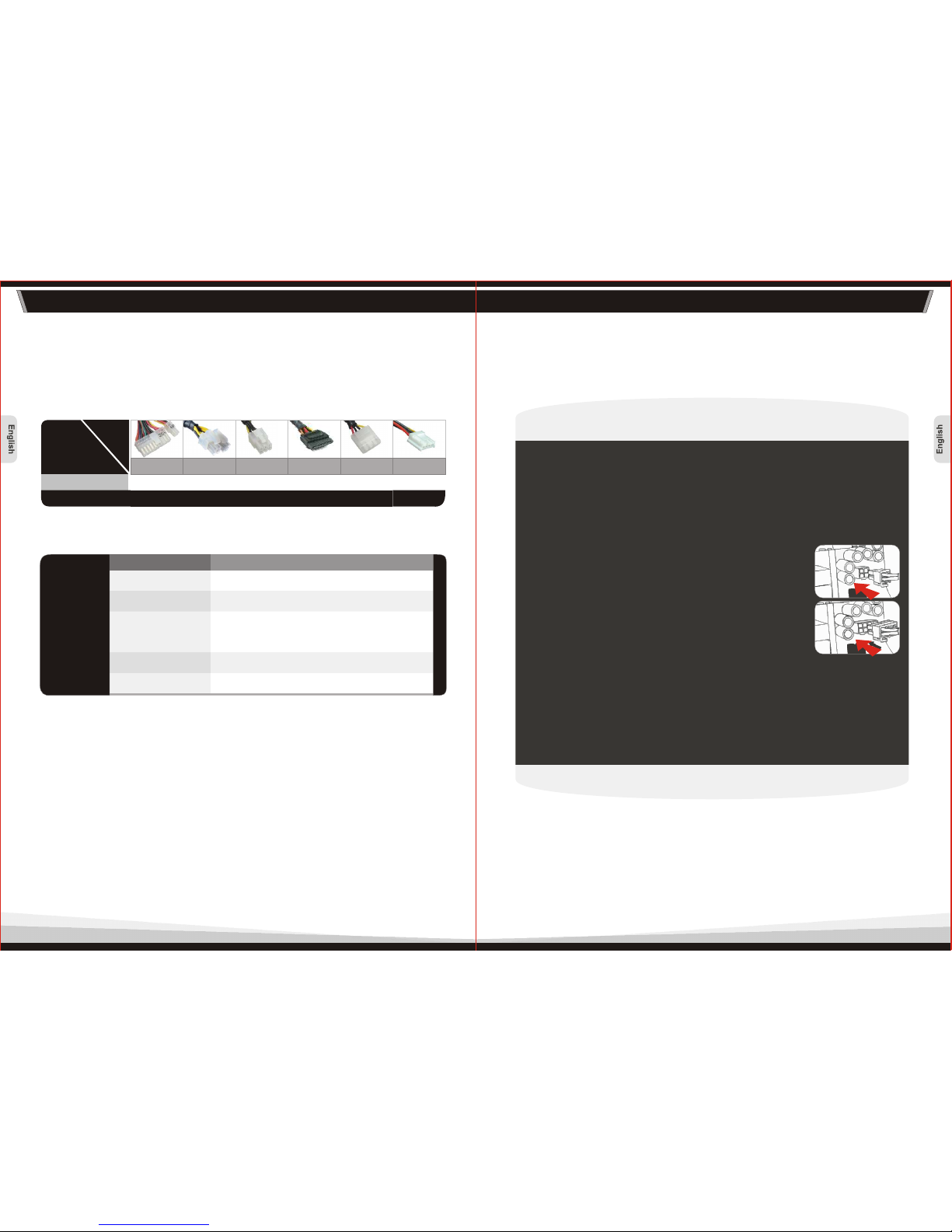
1. Open your computer case; please refer to the direction in your
case manual.
2. Install the PSU into the case with the four screws provided.
3. Connect the 24 pin Main Power Connector to your
motherboard and peripheral. If your motherboard uses a 20-pin
connector, detach the 4-pin attachment on the 24-pin connector.
5. Connect other peripheral power connectors to devices such as
hard drives, optical drives, etc.
6. Close your computer case and connect the AC power cord to
the power supply AC inlet.
Note: The detachable 4-pin section cannot be used in place of a
4-pin +12V connector.
Note: Make sure that your system is turned off and unplugged.
Disconnect the AC power cord from your old power supply.
MODEL
Connector Type Connectors & Cable length
20+4pin
ATX 12V 4+4pin
Molex & FDD
SATA
1 x 20+4pin Main connector
(500mm)
3 x Peripheral & 1 x FDD connectors
(500mm + 100mm + 100mm + 100mm)
3 x Peripheral & 1 x FDD connectors
(500mm + 100mm + 100mm + 100mm)
2 x S-ATA connectors
(500mm + 100mm)
1 x 6pin PCI-E connector
(500mm)
Cable
P/N Model
W0070 430W 1 1 1 2 6 2
20+4pin Main
Connector
4+4pin +12V
CPU Connector
SATA
Connector
Peripheral
Connector
Floppy
Connector
6pin PCI-E
Connector
PCI-E 6pin
1 x ATX 12V 4+4pin connector
(500mm)
430W
4.1 For motherboard that requires a single 4pin
auxiliary (CPU) power connector, please separate
the 4+4pin EPS connector. Please note, after
separating the 4+4pin EPS connector, only one
4pin connector can be used to connect to the 4pin
auxiliary (CPU) receptacle connector on the
motherboard.
4.2 For motherboard that requires a single 8pin EPS connector,
please use the 4+4pin EPS connector from the power supply
Page 5
TR2 430W TR2 430W
ATX 12V 2.2 Version ATX 12V 2.2 Version
5. Product Features
05 06
- ATX12V V2.2 enables most reliable and robust power delivery.
- Dedicated dual +12V rails ensures efficient power delivery to
critical components within the PC.
- Supports all Intel & AMD processors.
- Supports all Nvidia & ATI/AMD graphic cards.
- Industrial-grade components makes TR2 430W the most reliable
power supply in its class: MTBF > 100,000 hours.
- Build-in intelligent fans automatically adjusts fan speed
according to different temperature to lower overall noise level for a
more enjoyable computing experience.
- Selectable115 / 230V AC input voltage for different country.
- Advanced Safety Protections: Over Power, Over Voltage, and
Short-Circuit protection.
- Safety / EMI Approvals: UL / CUL, FCC, BSMI and GOST
certified.
6. Output Specification
7. Total Protection
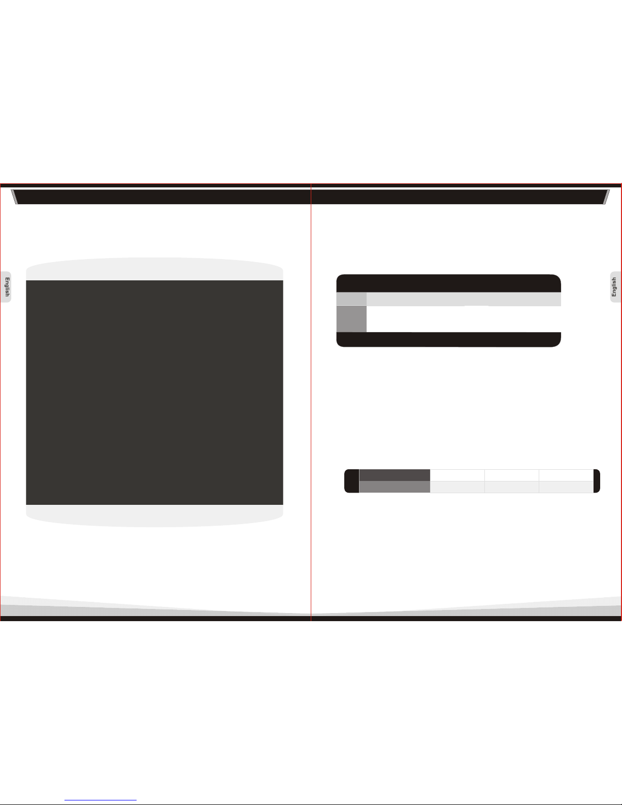
* Over Voltage Protection
* Short Circuit Protection
Activated when any DC rails short circuited.
* Over Power Protection
Voltage Source
Protection Point
+3.3V
+5V
+12V
4.5V Max.
7.0V Max.
15.6V Max.
+5Vsb
-12V+12V1
+3.3V
+5V
MODEL
AC INPUT:
115Vac/10A , 230Vac/5A, FREQUENCY: 50Hz-60Hz
2A
0A
0.3A
0A
14A
1A
25A
28A
430W
+12V2
15A
1A
DC OUTPUT
Max Output
Current
Min Current
Current
0.5A 0.3A
The +5V and +3.3V Max-combined power is 130W.
The +5V, +3.3V and +12V max-combined power is 390W.
The power supply shall shutdown when loading is over 110% to 150%
of max rated load.
Page 6
TR2 430W TR2 430W
ATX 12V 2.2 Version ATX 12V 2.2 Version
8. EMI & SAFETY
9. Environments
07
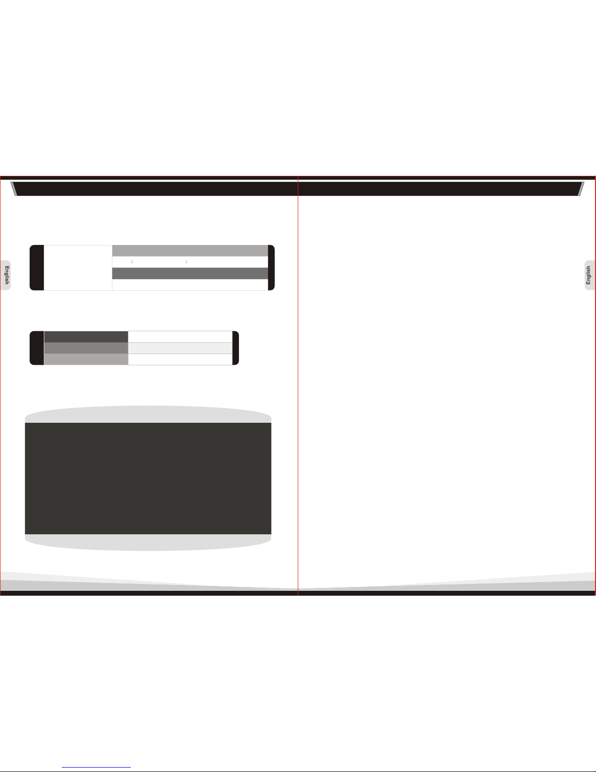
SAFETY Standards
EMI Regulatory
UL/CUL, BSMI, GOST
W0070 (430W)
FCC Class B, CISPR 22 Class B
If the power supply fails to function properly, please follow the troubleshooting
guide before application for service:
If the power supply is still unable to function properly after following the above
instruction, please contact you local store or Tt branch office for after sales service.
You may also refer to Thermaltake's website for more technical support:
1. Is the power cord plugged properly into electrical outlet and into the
power supply AC inlet?
2. Please make sure all power connectors are properly connected to all
the devices.
3. If connected to a UPS unit, is the UPS on and plugged in?
www.thermaltake.com
10. Trouble-Shooting
Operating temperature:
Operating humidity:
MTBF
oo
10 C to +2 5 C
20% to 85%,relative humidit
> 100, 000 hours.
 Loading...