

Page 1
Design Collaboratio n by Thermaltake
and Wate rmo d Fra nce
User's Man ual
Benutzer handbuch
Mode d’emp loi
Manual del u suario
Manuale de ll’utente
Manual do Ut ilizador
安裝說明書
用戶手冊
ユーザーズマニュ アル
Руководс тво пользователя
kullanıcı elk itabı
(EEE Yönet meliğine Uygundur)
คู่มือการใช้
© 2 016 T herma ltake Technol ogy C o., L td. Al l Rig hts R eserv ed. A-2 016.1 0
All other r egiste red tra demarks belon g to t heir res pectiv e compa nies.
Tested To C omply
With F CC Standa rds
FOR H OME OR O FFICE USE
www. therm altak e.com
ww w.t he rm al ta ke .c om
Page 2
Join Tt Community To Rece ive Bene fit s
Dear Valued Customer,
Thank you for choosing Thermaltake.
As a new user we value your thoughts and opinions and
your feedback is important to us. We at Thermaltake
would like to use this opportunity to invite you to join our
Community Forums. Register today to start enjoying the
full benefits of our community.
Benefits of being a member:
Quick and responsive user support
Receive help and advice with new builds
Keep up to date with new product releases
Share your thoughts and builds with the community
Enter monthly contests and giveaways
Tt LCS-Liquid Cooling Support Ce rti fication
Tt LCS Certified is a Thermaltake exclusive certification
applied to only products that pass the design and
hardcore enthusiasts standards that a true LCS chassis
should be held to. The Tt LCS certification was created
so that we at Thermaltake can designate to all power
users which chassis have been tested to be best
compatible with extreme liquid cooling configurations to
ensure you get the best performance from the best
features and fitment.
Bra nd off icia l webs ite
htt p:// www.t herm alta ke.c om/
Glo bal Fa cebo ok
htt ps:/ /www. face book .com /The rmaltakeInc
Taiwa n Facebook
htt p:// www.f aceb ook. com/ ThermaltakeTW
Glo bal co mmun ity fo rums
htt p:// comm unity.thermaltake.com
Content s
Chapter 1. Product Introduction
1.0
Sp ecifica ti on
1.1
Ac cessory
1.2
War ni ng an d N otice
Chapter 2. Installation Guide
Parts Disa ss embly
2.0
Power Supp ly Un it (P SU) I nstal la tion
2.1
Mo therboa rd In stall at ion
2.2
5. 25" D evice Inst al latio n
2.3
3. 5" & 2 .5 " H DD In st allat io n
2.4
PC I C ar d I ns talla ti on
2.5
Ai r C oo ling Insta ll ation
2.6
Li quid Cooli ng In st allat io n
2.7
Pu mp In stall at ion
2.8
Chapter 3. Leads Installation Guide
Ca se LE D c onnecti on
3.0
US B 3 .0 co nnectio n
3.1
Au dio c onnec ti on
3.2
01
01
02
04
07
08
09
10
12
13
14
15
16
16
16
Page 3
Specification
Warn ing and Notice
Accessory
1
Figure
Cas e Type
Dim ensio n (H*W* D) 752 x 4 23 x 483 mm ( 29.6 x 16 .7 x 19 inc h)
Coo ling Sy stem
Dri ve Bays
- Acce ssibl e
- Hid den
Exp ansio n Slots
Mot herbo ards
I/O P ort
PSU
Fan S uppor t
Rad iator S uppor t
Cle aranc e
Parts Name
Screw#6-32 x 6.5mm
Stand-off#6-32 x 6mm
Stand-off#6-32 x 6mm
Screw M3 x 5mm
Screw M3 x 5mm
Nut Setter
Wrench M5
Stand-off#M5 x 14mm
Screw Ø5 x 12mm
Stand-off#6-32 x 29mm
Cable Ties
Buzzer
Spring
USB 2 .0 cabl e(AF- AM) 1.0 m
Sup er Tower
Top (e xhaus t) :
140 x 1 40 x 25 mm Tur bo fan (1 000rp m, 16dB A) x 2
1 x 5.2 5”
6 x 3.5 ” or 2.5” ( With HD D Cage)
2 x 2.5 ” (With H DD tray )
8
6.7 ” x 6.7” (M ini ITX ), 9.6” x 9 .6” (Mi cro ATX),
12” x 9 .6” (ATX ) , 12” x 13” ( E-ATX)
USB 3 .0 x 4, HD Aud io x 1
Sta ndard P S2 PSU (o ption al)
Lef t Side:
4 x 120 mm , 4 x 140m m
Rig ht Side :
4 x 120 mm , 4 x 140m m
Top:
2 x 120 mm , 2 x 140m m
Rea r:
2 x 120 mm , 2 x 140m m
HDD C age:
1 x 120 mm , 1 x 140m m
Lef t / Right S ide:
1 x 480 mm , 1 x 560m m
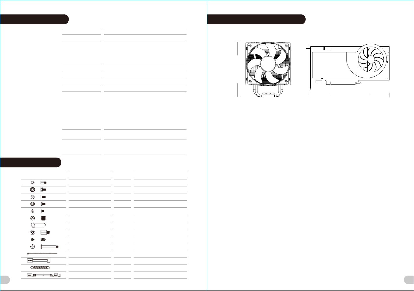
CPU c ooler h eight l imita tion: 2 60mm
VGA le ngth li mitat ion: 40 0mm
PSU l ength l imita tion: 2 20mm
Q'ty
4
4
24
26
24
1
1
12
8
4
10
1
2
2
Used for
Motherboard
Power
3.5 " HDD
MB, O DD, 2.5 " HDD / SSD
2.5" HDD / SSD
MB St and-o ff
Sta nd-of f M5
Acr ylic
Case Fan (rear)
Fan
Cable Management
Motherboard Alarm
Backup
Mouse & Keyboard
<2 60 mm
<4 00 mm
War ning!!
CPU Cooler Height Limitation:
Please ensure that your CPU cooler does NOT exceed 260mm (10.2 inches) height.
VGA (Add-on card) Length Limitation:
Please ensure that your VGA (Add-on card) does NOT exceed 400mm (15.7 inches) length.
Warnun g!!
CPU-Kühler Höhenbeschränkung:
Bitte stellen Sie sicher, dass Ihr CPU-Kühler 260 mm (10,2 Zoll) Höhe nicht überschreitet.
VGA (Add-on-Karte) Längenbeschränkung:
Bitte stellen Sie sicher, dass Ihre VGA (Add-on-Karte) 400 mm (15,7 Zoll) Länge nicht
überschreitet.
Averti ssement !
Limite de hauteur du ventilateur de CPU :
Vérifiez que la hauteur du ventilateur de CPU ne dépasse pas 260 mm.
Limite de longueur de la carte (complémentaire) VGA :
Vérifiez que la longueur de votre carte (complémentaire) VGA ne dépasse pas 400 mm
Precaución
Limitación de altura del refrigerador de CPU:
Asegúrese de que la altura de su refrigerador de CPU no excede los 260 mm (10,2 pulgadas).
Limitación de longitud de la tarjeta de vídeo (adicional):
Asegúrese de que la longitud de su tarjeta de vídeo (adicional) no excede los 400 mm (15,7
pulgadas).
Attenzione!
Limitazione altezza dissipatore CPU:
Assicurarsi che l’altezza del dissipatore CPU NON superi 260 mm (10,2 pollici).
Limitazione lunghezza VGA (scheda aggiuntiva):
Assicurarsi che la lunghezza del VGA (scheda aggiuntiva) NON superi 400 mm (15,7 pollici).
2
Page 4
Atençã o!!
Limite d e alt ura para o dissi pad or do CPU:
O limite d e alt ura para o dissi pad or do CPU é 260 mm (10 ,2 po legadas).
Limite d e com primento par a VGA ( placa gráfic a):
O limite d e com primento par a VGA ( placa gráfic a) é 40 0 mm (15.7 poleg ada s).
警告!!
CPU 冷卻器的 高度限 制:
請確保 CPU 冷卻 器的高 度不超過 260 mm (10. 2 英吋)。
VGA (附加介面 卡) 的長度 限制:
請確保 VGA (附加 介面卡) 的 長度不超過 400 mm (15 .7 英吋)。
警告!!
CPU 散热器高 度限制 :
请确保 CPU 散热 器的高 度不超过 260 mm(10.2 英 寸)。
VGA(附加卡 )长度 限制:
请确保 VGA(附 加卡) 的长度不超过 400 mm(15 .7 英寸 )。
警告
CPUクーラー の高さ 制限:
CPUクーラー の高さ が260mmを超えていな いこと を確認してください。
VGA(アドオ ンカー ド)の長さ制限:
VGA(アドオ ンカー ド)の長さが400mmを 超えて いないことを確認して くださ い。
Вниман ие!
Ограни чен ие по высоте охл ади теля ЦП
Убедит есь, ч то высота охла дит еля ЦП (централ ьно го процессор а) НЕ пр евышает 260 м
(10,2 дю йма) .
Ограни чен ие по длине виде ока рты VGA (плата ра сши рения)
Убедит есь, ч то длина видео кар ты VGA (плата рас шир ения) НЕ превыш ает 4 00 мм
(15,7 дю йма) .
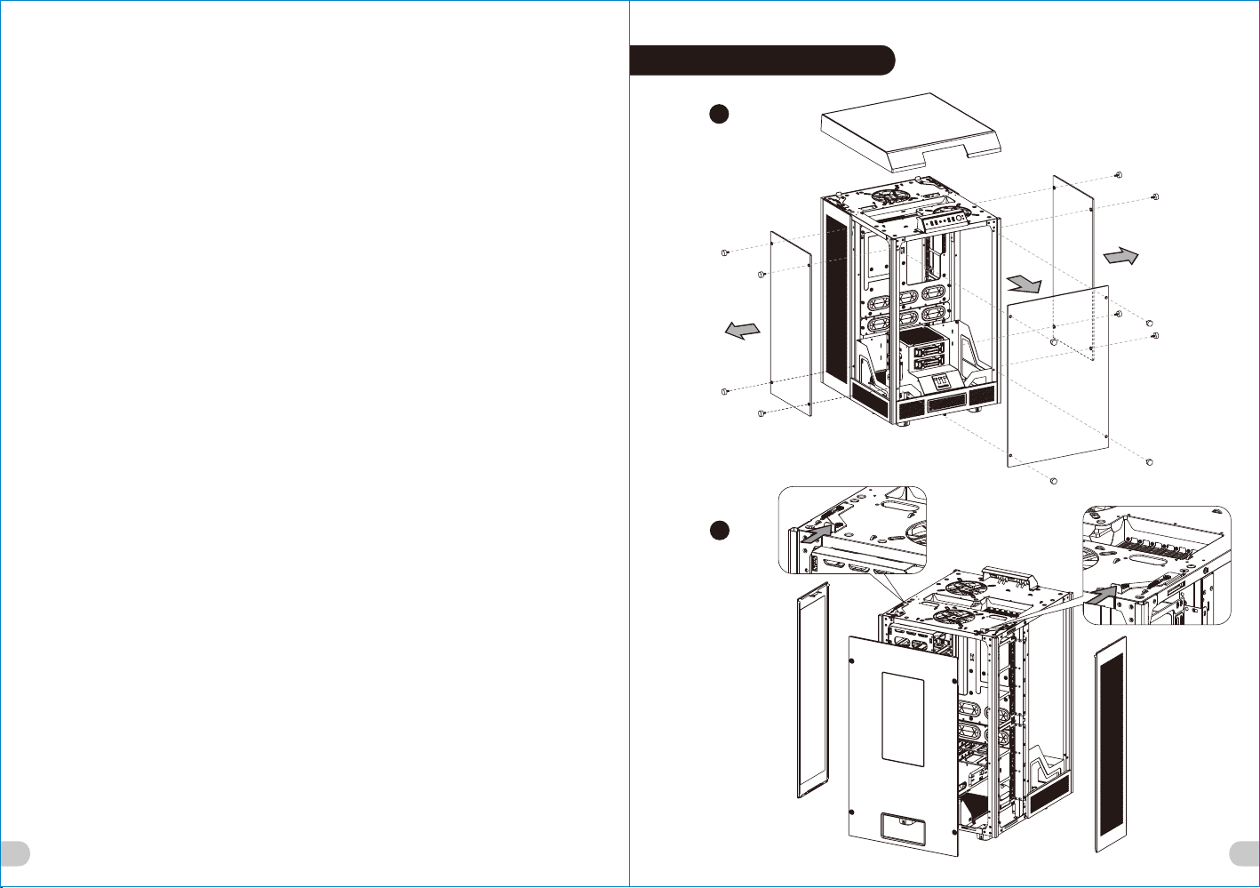
Parts Disa sse mbl y
1
2
Uyarı!!
CPU Soğu tuc u Yükseklik Sınırl ama sı:
Lütfen C PU so ğutucunuzu n yük sekliğinin 2 60m m’yi (10,2 inç ) GEÇ MEDİĞİNDEN e min o lun.
VGA (Ekl ent i kartı) Uzunluk Sınır lam ası:
Lütfen V GA’ nızın (Eklenti kar tı) uzu nluğunun 400 mm’ yi (15,7 inç) GE ÇME DİĞİNDEN emi n
olun.
คำเตือน!!
ขีดจำกัดความสูงสำหรับฮีตซิงก์ของ CPU:
ขีดจำกัดความสูงสำหรับฮีตซิงก์ของ CPU คือ 260 มม. (10.2 นิ้ว)
ขีดจำกัดความยาวสำหรับ VGA (การ์ดแสดงผล):
ขีดจำกัดความยาวสำหรับ VGA (การ์ดแสดงผล) คือ 400 มม. (15.7 นิ้ว)
3
4
Page 5

3
5
4
5
6
6
Page 6

Power Supp ly Un it (PSU) Installation
Motherboard Insta lla tio n
English /
1. Pl ace the PSU in proper location.
2. Ad just the PSU supporting bridge to the proper
location and secure the PSU with screws.
Deutsch /
1. Pl atzieren Sie das Netzteil in der richtigen
Position.
2. Ri chten Sie die Stützbrücke für das Netzteil
entsprechend aus und sichern Sie das Netzteil
mit Schrauben.
Français /
1. Pl acez l’alimentation dans la position appropriée.
2. Aj ustez le pont de support de l’alimentation dans
la position appropriée et fixez l’alimentation à
l’aide des vis.
Español /
1. Instale la PSU en la ubicación correcta.
2. Aj uste el puente de soporte de la PSU en la
ubicación adecuada y asegúrela con tornillos.
Itali ano /
1. Po sizionare la PSU in modo corretto.
2. Re golare il ponticello di supporto della PSU nella
posizione corretta e fissare la PSU con delle viti.
Portu guês/
1. Co loque o PSU na sua devida posição.
2. Aj uste a ponte de suporte do PSU para a devida
posição e fixe o PSU com parafusos.
7
繁體中文 /
1. 將電 源供應器放在正確的位置
2. 將電 源供應器支撐架調整到適當的位置,然後用螺 絲
固定電源供 應器。
简体中文 /
1. 将电 源供应器放在正确的位置
2. 将电 源供应器支撑架调整到适当的位置,然后用螺丝
固定电源供 应器。
日本語 /
1. PSUを適切なロケーションに取り付けます。
2. PSU支持ブリッジを適切なロケーションに合うよう
に調整し、 ねじでPSUを締め付けます。
Русск ий /
1. Ус тановите блок питания в надлежащее место.
2. Надлежащим образом установите
поддерживающий мост блока питания и закреп
ите блок питания винтами.
Türkç e /
1. PSU’yu, uygun konuma yerleştirin.
2. PSU destek köprüsünü uygun konuma ayarlayın ve
PSU’yu vidalarla sabitleyin.
ภาษาไทย /
1. วาง PSU ในตำแหน่งที่เหมาะสม
2. ขยับบริดจ์ที่รองรับ PSU ให้อยู่ในตำแหน่งที่เหมาะสม
แล้วขันสกรูยึด PSU ให้แน่น
English /
Insta ll the motherboard in proper location and
secure it with screws.
Deutsch /
Insta llieren Sie die Hauptplatine in ihrer
vorgesehenen Position und sichern Sie sie mit
Schrauben.
Français /
Insta llez la carte mère dans l'endroit approprié et
sécurisez-la avec des vis.
Español /
Insta le la placa madre en la ubicación adecuada y
asegúrela con tornillos.
Itali ano /
Insta llare la scheda madre nella posizione
appropriata e fissarla con le viti.
Portu guês/
Insta le a motherboard no local adequado e aparafuse.
繁體中文 /
將主機板放 置在合適的位置並用零件包中之螺
絲固定。
简体中文 /
在合适的位 置安装主板并以螺丝安全固定。
日本語 /
マザーボー ドを適切な場所に取り付け、ねじで固定
します。
Русск ий /
Устан овите ма теринск ую плату в на длежаще е
место и закрепи те ее винта ми.
Türkç e /
Ana kartı uygun konuma takın ve vidalarla
sabitleyin.
ภาษาไทย /
ติดตั้งเมนบอร์ดในตำแหน่งที่เหมาะสม
แล้วขันสกรูยึดให้แน่น
8
Page 7

5.25" Device Installat ion 3.5" & 2.5" HDD Installati on
Type A: HDD In sta llation (W ith H DD Cage)
3.5 ” HDD
For 3 .5" H DD:
Secure 3 .5" H DD fro m bot h side
of th e HDD t ray b y lock ing c lips .
2.5 ” HDD /SS D
For 2 .5" H DD:
Secure 2 .5" H DD fro m the
bottom o f the H DD by sc rew s.
HDD Cag e Ins tallatio n
Right s ide Left si de
1
2
3
4
5
9
10
Page 8

Type B: HDD Ins tal lation (Wi th HD D Tray)
PCI Card Installati on
3.5 " HDD
For 3 .5" H DD:
Secure 3 .5" H DD fro m bot h side
of th e HDD t ray b y lock ing c lips .
2.5 " HDD /SSD
For 2 .5" H DD:
Secure 2 .5" H DD fro m the
bottom o f the H DD by sc rew s.
Type C: 2.5” HD D Ins tallatio n
11
2.5" HDD /SSD
For 2 .5" H DD:
Secure 2 .5" H DD fro m the
bottom o f the H DD by sc rew s.
English /
Insert the PCI card into the PCI slot, and
secure it with screw.
Deutsch /
Stecken Sie die PCI Karte in den PCI
Steckplatz und sichern Sie sie mit
Schrauben.
Français /
Insérez la carte PCI dans le slot PCI et
sécurisez-la avec des vis.
Español /
Inserte la tarjeta PCI en la ranura del PCI y
asegúrela con tornillos.
Italiano /
Inserire la scheda PCI nello slot PCI e
fissarla con la vite.
Português/
Insira a placa PCI na ranhura PCI e fixe
com parafusos.
繁體中文 /
將 PCI 卡插入 PCI 插槽,然後用螺絲固定。
简体中文 /
将 PCI 卡插入 PCI 插槽并以螺丝固定。
日本語 /
PCI カードを PCI スロットに挿入し、ねじ
で固定します。
Русский /
Вставьте PCI-карту в слот PCI и закрепи
те ее винтом.
Türkçe /
PCI kartını, PCI yuvasına yerleştirin ve
vidayla sabitleyin.
ภาษาไทย /
ใส่การ์ด PCI ในสล็อต PCI
แล้วขันสกรูยึดให้แน่น
12
Page 9

Air Cooling Install ati on
Top:
2 x 120mm
2 x 140mm
Rear:
2 x 120mm or 2 x 1 40m m
Liquid Cooling Inst all ation
Left / Ri ght Side:
1 x 120mm or 1 x 240mm or 1 x 360mm or 1 x 480 mm
1 x 140mm or 1 x 280mm or 1 x 420mm or 1 x 560 mm
Rear
12cm
14cm
14cm
Side
12cm
Top
14cm
12cm
HDD:
1 x 120mm or 1 x 1 40m m
Lef t / Rig ht Si de:
4 x 120mm
4 x 140mm
12cm
14cm
Side
14cm
12cm
Side
14x56 cm
14x42 cm
12x48 cm
Side
14x42 cm
14x56 cm
12x48 cm
13
12cm
14cm
HDD
14
Page 10

Pump Installation
Leads Installatio n
English
Leads Ins tallation Gu ide
Case LED C onn ect ion / On t he fron t of the ca se, you c an find s ome LED s and swi tch lea ds. Ple ase con sult yo ur user
man ual of yo ur moth erboa rd manu factu rer, th en conn ect the se lead s to the pa nel hea der on th e mothe rboar d.
USB 3.0 co nne cti on /
1. Ma ke sure y our mot herbo ard sup ports U SB 3.0 co nnect ion.
2. Co nnect t he USB 3. 0 cable t o the ava ilabl e USB 3.0 p ort on yo ur comp uter.
Aud io Co nne ction / Ple ase re fer to th e follo wing il lustr ation o f Audio c onnec tor and y our mot herbo ard use r manua l.
Ple ase sel ect the m other board w hich us ed AC’9 7 or HD Aud io(Az alia) ,(be aw are of th at your a udio su pport s AC’97 o r HD
Aud io (Aza lia)) o r it will d amage y our dev ice(s ).
Deutsch
Ansch lüsse h er stellen
Gehäus e-L ED- Verb indu nge n / Auf de r Gehäu sevor derse ite fin den Sie e inige L EDs und V erbin dunge n. Bitt e nehme n
Sie d ie Gebr auchs anwei sung Ih res Mot herbo ard Her stell ers zur H ilfe un d schli eßen Si e diese V erbin dunge n an die Pa nel
Hea der Bel egung d es Moth erboa rds an.
USB 3.0 An sch luss /
1. St ellen S ie sich er, das s Ihre Ha uptpl atine d en USB 3. 0 Ansch luss un terst ützt.
2. Ve rbind en Sie da s USB 3.0 K abel mi t dem USB 3 .0 Port a uf Ihre m Compu ter.
Aud io An schlüss e / Bitte beachten Sie di e folg ende A bbil dung de r Audio A nschl üsse un d die Anw eisun g in der
Geb rauch sanwe isung I hres Mo therb oards . Bitte w ählen S ie das Mo therb oard, d as AC’9 7 oder HD A udio( Azali a)
ver wende t, (ach ten Sie d arauf , dass Ih r Audio A C’97 bz w. HD Aud io (Aza lia unt erstü tzt)) . Ander nfall s entst ehen sc hwere
Sch äden an I hrem( n) Gerä t(en) !!!
L- OUT
SE NSE
R-O UT
MI C-P OWE R
MI C-I N
L- OUT
SE NSE 2
KE Y
SE NSE 1
PR ESE NSE
GN D
L- RET
KE Y
R-O UT
R-R ET
MI C-P OWE R
MI C-I N
USB 3.0 Co nnectio n
GN D
15 16
Page 11

Français
Guide d'in stallation des fil s
Con nexio n des voyants du boîtier / S ur la fa ce avan t du boî tier, vous tr ouverez plusieurs voyant s et les fils de s
bout ons. S' il vous plaît c onsultez le guide d'utili sateur du fabricant de vot re car te mèr e, puis connect ez ces f ils aux
onne cteurs sur la c arte mè re.
Con nexio n USB 3.0 /
1. Vé rifie z que vot re cart e mère pr end en ch arge la c onnex ion USB 3 .0.
2. Co nnect ez le câb le USB 3. 0 au port U SB 3.0 di sponi ble sur v otre or dinat eur.
Con nexio n Aud io / S' il vous plaît r éférez vous à l'illustrati on suiv ante d u connecteur audio et au g uide de l'utilisateu r de
votr e carte mère. S 'il vous plaî t séle ctionnez un e cart e mère supportant AC'97 o u HD Au di (Aza lia), (faites att ention que
votr e audio suppor te l'A C'97 o u HD Au dio (Az alia)) sinon cela p ourrait end ommager votre matériel.
Italiano
Guida di insta llazione dei contatti
Con nessione d el LE D del case / Nella parte a nteriore del case, sono pr esenti alcuni con tatti per in terruttori e LED.
Cons ultare il manu ale ut ente d el pro duttore della s cheda m adre, quindi connettere i cont atti a lla pa rte su periore del
pann ello su lla sch eda ma dre.
Con nessione U SB 3. 0 /
1. Ac certa rsi che l a sched a madre s uppor ti la con nessi one USB 3 .0.
2. Co llega re il cav o USB 3.0 a lla por ta USB 3. 0 dispo nibil e sul com puter .
Connes sio ne Audio / Fa re rife rimen to all’ illus trazi one rip ortat a di segu ito del c onnet tore Au dio e al ma nuale u tente p er
la sc heda ma dre.S elezi onare l a sched a madre r elati va a AC’9 7 o HD Audi o (Azal ia) e con sider are che i l suppo rto aud io è
com patib ile con A C’97 o HD A udio (A zalia ); in cas o contr ario, l e perif erich e potre bbero v enire d anneg giate .
Español
Guía de Instal ación de Ca bles
Con exión del L ED de la caja / E n la par te fron tal de l a caja, encontr ará alg unos LED y cab les de i nterrup tores. Consult e
el m anual del us uario del fabricant e de la placa madre, a con tinuaci ón cone cte est os cab les al conector de l a placa madre.
Con exión USB 3 .0 /
1. As egúre se de que l a placa b ase adm ite con exión U SB 3.0.
2. Co necte e l cable U SB 3.0 al p uerto U SB 3.0 di sponi ble en el e quipo .
Con exión de Au dio / Consult e la sig uiente ilustra ción de l conector de Audio y el manu al del usuario de la placa m adre.
Sele ccione la plac a madr e que u tiliza AC’97 o HD Aud io (Azalia), (asegúrese de que su audi o admi te AC’ 97 o HD Audio
(Aza lia)) s i no, su s dispo sitivos resultará n dañad os
L- OUT
SE NSE
R-O UT
MI C-P OWE R
MI C-I N
L- OUT
R-O UT
MI C-P OWE R
MI C-I N
USB 3.0 Co nnectio n
SE NSE 2
KE Y
SE NSE 1
PR ESE NSE
GN D
L- RET
KE Y
R-R ET
GN D
Português
Guia de Ins talaç ão Eléc trica
Ligaçã o do LE D da Ca ixa / Na p arte di antei ra da cai xa pode e ncont rar alg uns LED s e fios el éctri cos. Co nsult e o
man ual de ut iliza dor do fa brica nte da su a mothe rboar d e ligue o s fios à pa rte sup erior d o paine l na moth erboa rd.
Ligaçã o USB 3 .0 /
1. Ce rtifi que-s e que a sua m other board s uport a ligaç ão USB 3. 0.
2. Li gue o cab o USB 3.0 à p orta US B 3.0 dis ponív el no seu c omput ador.
Ligaçã o Áud io / Con sulte a i magem s eguin te do con ector Á udio e o ma nual de u tiliz ador da s ua moth erboa rd.
Sel eccio ne a moth erboa rd que ut iliza A C’97 ou H D Áudio (Azal ia), (v erifi que se a su a placa d e áudio s uport a AC’97 o u HD
Áud io(Az alia) ) ou irá da nific ar o(s) s eu(s) d ispos itivo (s).
L- OUT
SE NSE
R-O UT
MI C-P OWE R
MI C-I N
L- OUT
R-O UT
MI C-P OWE R
MI C-I N
USB 3.0 Co nnectio n
SE NSE 2
KE Y
SE NSE 1
PR ESE NSE
GN D
L- RET
KE Y
R-R ET
GN D
17 18
Page 12

繁體中文
線材安裝說明
機殼LE D連接方式 / 在機 殼前方的面 板後面,可 以找到一些L ED與開關線 材(POWE R Switc h….),請 參考主機板 使用說明書 ,
並將機 殼上的線材 正確地連接 到主機板上 ,這些線材 通常都會印 有標籤在上 面,如果沒 有的話,請 找出機殼前 方面板上線 材原
本的位 置以知道正 確的來源。
USB 3 .0 連接 /
1. 請確 認主機板是 否支援USB 3 .0傳輸介面 。
2. 連接U SB 3.0傳輸 線至主機板 上的USB3 .0接埠。
音效連 接 / 請根據下面 的音源接頭 圖示與主機 板使用手冊 來連接音效 裝置,請確 認主機板上 的音效裝置 是支援AC' 9 7音效或是
HD音效( Azali a),裝置錯 誤可能會導 致主機板音 效裝置的毀 損,某些主 機板的音效 裝置不會與 下方的圖示 完全相同, 請參酌主
機板使 用手冊以得 到正確的安 裝資訊
日 本語
リード線の取り付けガイド
ケース LED の 接続 / ケー ス前面には、L EDとスイッチリード線が あります。 マザーボードメーカーのユ ーザーマニュアル
を参照し 、これらのリ ード線をマザ ーボードのパ ネルヘッダに接続してく ださい。
USB 3.0 の接 続 /
1. お 使いのマザーボードがUS B 3.0接続を サポートしていることを 確認してくだ さい。
2. U SB 3.0ケ ーブルをコンピュータの 空いているUSB 3.0ポー トに接続しま す。
オーディ オ接続 / オーディオコ ネクタの次の 図とマザーボードのユー ザーマニュアルを参照して ください。AC’97または
HDオーデ ィオ(Azal ia)を使用するマザーボ ードを選択してください(オー ディオがAC’97またはHDオー ディオ(Aza lia)をサポ
ートして いることを確 認してくださ い)。サポートし ていないと、デバイスが 損傷します)。
简体中文
线材安装说明
机壳LED连 接方式 / 在机壳前方的 面板后面,可 以找到一些LED与开关线材 (POWER S witch….),请参考 主板使用说明
书,并将 机壳上的线材 正确地连接到 主板上,这些 线材通常都会印有标签在 上面,如果没有的话,请找 出机壳前方面 板上线
材原本的 位置以知道正 确的来源。
USB 3.0 连接 /
1.请确认 主板是否支持USB 3.0传 输接口。
2.连接US B 3.0传输线 至主板上的USB3.0接 埠。
音效连接 / 请根据 下面的音源接 头图示与主板 使用手册来连接音效装置 ,请确认主板上的音效装置 是支持AC' 9 7音效或是
HD音效(A zalia), 装置错误可能会导致主板 音效装置的毁损,某些主板 的音效装置不会与下方的图 标完全相同, 请参酌主板
使用手册 以得到正确的 安装信息
L- OUT
SE NSE
R-O UT
MI C-P OWE R
MI C-I N
L- OUT
R-O UT
MI C-P OWE R
MI C-I N
USB 3.0 Co nnectio n
SE NSE 2
KE Y
SE NSE 1
PR ESE NSE
GN D
L- RET
KE Y
R-R ET
GN D
Русский
Указания по прокладке к абе лей
Под ключе ние и ндика торов корп уса / В пер едней част и кор пуса распо ложен ы инд икато ры и прово да вы ключа телей.
Пер ед по дсоед инени ем эт их пр оводо в к м онтаж ной к олодк е пан ели н а мат еринс кой п лате изучи те ру ковод ство пол
ьзо вател я про извод ителя мате ринск ой пл аты.
Под ключе ние U SB 3.0 /
1. У бедит есь, чт о мат еринс кая п лата подде ржива ет по дключ ение по ст андар ту US B 3.0.
2. П одсое динит е каб ель U SB 3.0 к сво бодно му по рту U SB 3.0 компь ютера.
Под ключе ние а удиор азъем а / См. следу ющую иллюс траци ю ауд иораз ъема и рук оводс тво п ользо вател я мат еринс ко
й п латы. В ыбери те ма терин скую плату, в кот орой испол ьзует ся ко дек A C'97 и ли HD Audio (Azal ia) (уб едите сь, что зв
уко вая п лата подде ржива ет ко дек A C'97 и ли HD Audio (Azal ia)). В про тивно м слу чае м ожно повре дить устро йства.
L- OUT
SE NSE
R-O UT
MI C-P OWE R
MI C-I N
L- OUT
R-O UT
MI C-P OWE R
MI C-I N
USB 3.0 Co nnectio n
SE NSE 2
KE Y
SE NSE 1
PR ESE NSE
GN D
L- RET
KE Y
R-R ET
GN D
2019
Page 13

Türkçe
Ara Kablo Kurulum Kılavuzu
Kasa ışık bağ lantısı / Kas anın ön kısmınd a bazı ı şıklar ve anah tar ar a kabl oları görebil irsini z. Lüt fen an akart üretici nizin
sağl adığı k ullanım kılavu zuna ba kın ve daha so nra, b u ara k abloları, an akart üzerindeki panel bağlantı noktalar ına bağ layın.
USB 3.0 Ba ğlantısı /
1. Ana kar tınızın USB 3 .0 bağl antısını d esteklediğin den emi n olun.
2. U SB 3.0 kablosunu, bilgisa yarınızdaki kull anılabilir USB 3.0 b ağlantı nokt asına ba ğlayın.
Ses Bağlantısı / Lütfen aşa ğıdaki Ses k onektörü re smine ve ana kartınızın kullanım kılavuzu na bakı n. Lütf en AC’ 97 vey a HD
Audi o(Azal ia) sp esifikasyon unu kul lanan bir ana kart s eçin ( ses sistemini zin AC’ 97 veya HD Audi o (Aza lia) s pesifikasyo nunu
dest ekledi ğini u nutmayın); aksi t akdirde, aygıt(la r)ınız zarar görür.
ภาษาไทย
คู่มือการติดตั้งสา ยไฟ
การ เชื่อ มต่อไ ฟ LED ของ เคส / ท ี่ด้านห น้าของเ คส คุณจะเ ห็น ไฟ LED และส ายไฟของ สวิตซ์
กรุ ณาศึก ษาราย ละเอี ยดจ ากคู่มื อผู้ใช้ ของ ผู้ผ ลิต แผงวงจร หลักของ คุณ
จาก นั้นใ ห้เ ชื่อมต่ อสายไฟเ หล่านี้ เข้ ากับส่ว นหัวของ แผงบนแผ งวง จรหลัก
การ เชื่อ มต่อ US B 3.0 /
1. ตร วจด ูให้แน่ ใจว่าแผ งวงจรหล ักข องคุณรอ งรับการ เชื่อมต ่อ US B 3.0
2. เช ื่อ มต่อสาย U SB 3.0 เข้า กับพอร์ ต USB 3 .0 ที่สาม ารถใช้ง านได้บน คอม พิวเ ตอร์ข องคุณ
การ เชื่อ มต่ออ ุปกรณ ์รั บส่งสัญ ญาณเสีย ง/ กรุณาด ูรา ยละเอีย ดจากภาพ ประกอบข องต ัวเชื่อ มต่อสัญ ญาณเสีย งต่ อไปนี้
และ คู่มื อผู้ใ ช้ข องผู้ผล ิตแผงวง จรหลักข องค ุณ
กรุ ณาเลื อกแผง วงจ รหลักที ่ใช้ AC’9 7 หรื อ HD Aud io(Az ali a)
(กร ุณาตร วจสอบ ให้ แน่ใจว่ าอุปกรณ ์รับส่ง สัญ ญาณเสีย งของคุณ รองรับ AC ’97 ห รือ HD Audi o (Azalia ))
มิฉ ะนั้น อุป กรณ์ของ คุณอาจเ สีย หายไ ด้
21
USB 3.0 Co nnectio n
L- OUT
SE NSE
R-O UT
MI C-P OWE R
MI C-I N
L- OUT
R-O UT
MI C-P OWE R
MI C-I N
SE NSE 2
KE Y
SE NSE 1
PR ESE NSE
GN D
L- RET
KE Y
R-R ET
GN D
Page 14

 Loading...