

Page 1
©20 09 The rma lta ke Tech nol ogy Co., L td. All Rights Reser ved . 2 009 .08
All other r egis tered t radema rks belong to the ir respe ctive comp anies.
Tested To C omply
With F CC Standa rds
FOR H OME OR O FFICE USE
VL3 0001W1Z
User's Manual
Benutzerhandbuch
Mode d’emploi
Manual del usuario
Manuale dell’utente
安裝說明書
用戶手冊
ユーザーズマニュアル
Руководство пользователя
kullanıcı elkitabı
www. therm altak e.com
Page 2

Contents
Chapter 1. Product Introduction
Chapter 1. Product Introduction
1.1 Sp ec ifica ti on 02
1.2 Ac ce ssory
02
1.3 CP U Co oler He ig ht & VGA
(Add -o n card) L en gth Lim it ati on
03
Chapter 2. Installation Guide
2.1 Si de P anel Di sa ssemb ly
2.2 Motherboard I nstalla tion
2.3 Power Supply In stallat ion
2.4 5.25” Device Ins tallati on
2.5 HDD Device Inst allatio n
2.6 PCI Slot Instal lation
2.7 Installatio n of Red LED Li ght
05
07
11
15
24
29
30
Chapter 3. Leads Installation Guide
3.1 Ca se L ED conn ec tion
3.2 US B 2. 0 conne ct ion
3.3 Aud io c onnec ti on
31
31
31
Chapter 4. Other
Toughp ow er / Pure po wer /
TR2 po we r suppl y se ries (o pt ion al )
36
1.1 Specification
1.2 Accessor y
Fig ur e Name
Pro duct Na me
Mod el
Cas e Type
Dim ensio n
(D* W*H)
Weig ht
Coo ling Sy stem
Dri ve Bays
- Acce ssibl e
- Acce ssibl e
Mat erial
Col or
Fro nt I/O
Exp ansio n Slots
Mot herbo ards
PSU
Mot her Sta nd-of f
6#3 2 x L5 mm Scr ew
6#3 2 x L5 mm Scr ew
6#3 2 x L5 mm Scr ew
M3 x L6 m m Screw
M3 x L5 mm Scre w
Spea ker
Cab le Tie
Key C hain
Lev el 10
VL3 0001N 1Z
Gam ing Sta tion
614 x 3 18 x 666. 3 mm / 24.1 7 x 12.52 x 2 6.22 in ch
- Fro nt (int ake) : 14 0 x 140 x 25 mm R ed LED Fa n,
- Rea r(exh aust) : 1 20 x 120 x 25 m m Red LED F an, 130 0rpm, 1 7dBA
- HDD (inta ke) : Dua l 60 x 60 x 15m m Silen t Fan, 25 00 rpm, 1 9dBA
21. 37 kg / 47. 11 lb
100 0rpm, 1 6dBA or 12 0 x 120 x25 m m fan
9
3x 5. 25”
6 x 3.5 ”
Alu minum e xtrus ion
Bla ck
e-S ATA con necto r x 1, USB2 .0 x 4, HD Aud io
8
ATX / Mic ro ATX
Sta ndard P SII Pow er Supp ly(Op tiona l)
Q’t y Used fo r
10
10
4
24
12
18
1
5
1
Mot herbo ard
Mot herbo ard
PSU
3.5 ” HDD
CD- ROM
2.5 ” HDD
Mot herbo ard
Cab le Mana gemen t
Key
Key 2
Sid e Panel
1 2
Page 3

1.3 CPU C ooler Hei ght. VGA (Add- on card) & PSU Leng th Li mita tion
War in g!!
CPU Cooler Height Limitation:
Please ensure that your CPU cooler does NOT exceed 150mm (5.91 inches) height.
VGA (Add-on card) Length Limitation:
Please ensure that your VGA (Add-on card) does NOT exceed 310mm (12.20 inches) length.
PSU Length Limitation:
Please ensure that your PSU does NOT exceed 210mm (8.26 inches) length.
War nu ng!!
CPU-Kühler Höhenbeschränkung:
Bitte stellen Sie sicher, dass Ihr CPU-Kühler 150 mm (5,91 Zoll) Höhe nicht überschreitet.
VGA (Add-on-Karte) Längenbeschränkung:
Bitte stellen Sie sicher, dass Ihre VGA (Add-on-Karte) 310 mm (12,20 Zoll) Länge nicht
überschreitet.
PSU Längenbeschränkung:
Bitte stellen Sie sicher, dass Ihre PSU 210 mm (8.26 Zoll) Länge nicht überschreitet.
Ave rt iss em en t !
Limite de hauteur du ventilateur de CPU :
Vérifiez que la hauteur du ventilateur de CPU ne dépasse pas 150 mm.
Limite de longueur de la carte (complémentaire) VGA :
Vérifiez que la longueur de votre carte (complémentaire) VGA ne dépasse pas 310 mm.
Limite de longueur de la carte PSU :
Vérifiez que la longueur de votre carte PSU ne dépasse pas 210 mm.
Prec au ción
Limitación de altura del refrigerador de CPU:
Asegúrese de que la altura de su refrigerador de CPU no excede los 150 mm (5,91 pulgadas).
Limitación de longitud de la tarjeta de vídeo (adicional):
Asegúrese de que la longitud de su tarjeta de vídeo (adicional) no excede los 310 mm (12,20
pulgadas).
Limitación de longitud de la tarjeta de PSU:
Asegúrese de que la longitud de su tarjeta de PSU no excede los 210 mm (8.26 pulgadas).
警告!!
CPU 冷卻器的高度限制:
請確保 CPU 冷卻器的高度不超過 150 mm (5.91 英吋)。
VGA (附加介面卡) 的長度限制:
請確保 VGA (附加介面卡) 的長度不超過 310 mm (12.20 英吋)。
電源供應器 的長度限制:
請確保 電源供應器 的長度不超過 210 mm (8.26 英吋)。
警告!!
CPU 散热器高度限制:
请确保 CPU 散热器的高度不超过 150 mm(5.91 英寸)。
VGA(附加卡)长度限制:
请确保 VGA(附加卡)的长度不超过 310 mm(12.20 英寸)。
电源供应器 长度限制:
请确保 电源供应器 的长度不超过 210 mm(8.26 英寸)。
警告
CPUクーラーの高さ制限:
CPUクーラーの高さが150mmを超えていないことを確認してください。
VGA(アドオンカード)の長さ制限:
VGA(アドオンカード)の長さが310mmを超えていないことを確認してください。
PSU の長さ制限:
PSU の長さが210mmを超えていないことを確認してください。
Вниман ие!
Ограничение по высоте охладителя ЦП
Убедитесь, что высота охладителя ЦП (центрального процессора) НЕ превышает 150 мм
(5,91 дюйма).
Ограничение по длине видеокарты VGA (плата расширения)
Убедитесь, что длина видеокарты VGA (плата расширения) НЕ превышает 310 мм
(12.20 дюйма).
Ограничение по длине видеокарты PSU
Убедитесь, что длина видеокарты PSU НЕ превышает 210 мм (8.26 дюйма).
Atte nz ione!
Limitazione altezza dissipatore CPU:
Assicurarsi che l’altezza del dissipatore CPU NON superi 150 mm (5,91 pollici).
Limitazione lunghezza VGA (scheda aggiuntiva):
Assicurarsi che la lunghezza del VGA (scheda aggiuntiva) NON superi 310 mm (12,20 pollici).
Limitazione lunghezza PSU:
Assicurarsi che la lunghezza del PSU NON superi 210 mm (8.26 pollici).
Uyarı! !
CPU Soğutucu Yükseklik Sınırlaması:
Lütfen CPU soğutucunuzun yüksekliğinin 150mm’yi (5,91 inç) GEÇMEDİĞİNDEN emin olun.
VGA (Eklenti kartı) Uzunluk Sınırlaması:
Lütfen VGA’nızın (Eklenti kartı) uzunluğunun 310mm’yi (12,20 inç) GEÇMEDİĞİNDEN emin olun.
PSU Uzunluk Sınırlaması:
Lütfen PSU uzunluğunun 210mm’yi (8.26 inç) GEÇMEDİĞİNDEN emin olun.
3 4
Page 4
Chapter 2. Installation Guide
2.1 Side Panel Disassembly
1
2
Italiano /
1. Ruotare l'incavo per la chiavetta del
pannello laterale PSU/MB/SIDE PANEL in
posizione OPEN (APERTO) usando la
chiave.
2. Ruotare di nuovo l'incavo per la chiavetta
del pannello laterale ODD/HDD in
posizione LOCK (BLOCCATO) usando la
chiave.
3. Svitare le viti ad aletta superiori e inferiori
nella parte posteriore del pannello laterale
dello chassis ed estrarre la piastra
per aprirla.
日本語 /
1. キーを使って、側面パネルのPSU/MB/SIDE
PANELのキー穴を「開放」位置まで回します.
2. キーを使って、側面パネルのODD/HDDのキー
穴を「ロック」位置まで戻します.
3. シャーシ側面パネルの裏側の上下蝶ねじを外し、
プレートを引っ張り出してパネルを開けます.。
3
Русский /
1. Поверните отверстие под ключ на боковой
панели PSU/MB/SIDE PANEL
(БП/МП/БОКОВАЯ ПАНЕЛЬ) в положение
OPEN (ОТКРЫТО) с помощью ключа.
2. Поверните отверстие под ключ на боковой
панели ODD/HDD (ОД/ЖД) обратно в
положение LOCK (БЛОКИРОВКА) с
помощью ключа.
3. Открутите верхние и нижние винты с
накатанной головкой на задней части
боковой панели корпуса и сдвиньте панель,
чтобы открыть ее.
Türkçe /
1. Anahtarı kullanarak yan panelin PSU/MB/SIDE
PANEL deliğini OPEN (açık) konuma getirin.
2. Anahtarı kullanarak yan panelin ODD/HDD
deliğini tekrar LOCK (kilitli) konuma getirin.
3. Kasanın yan panelinin arkasında yer alan üst
ve alt kelebek vidaları gevşetin ve açmak için
plakayı kaydırın.
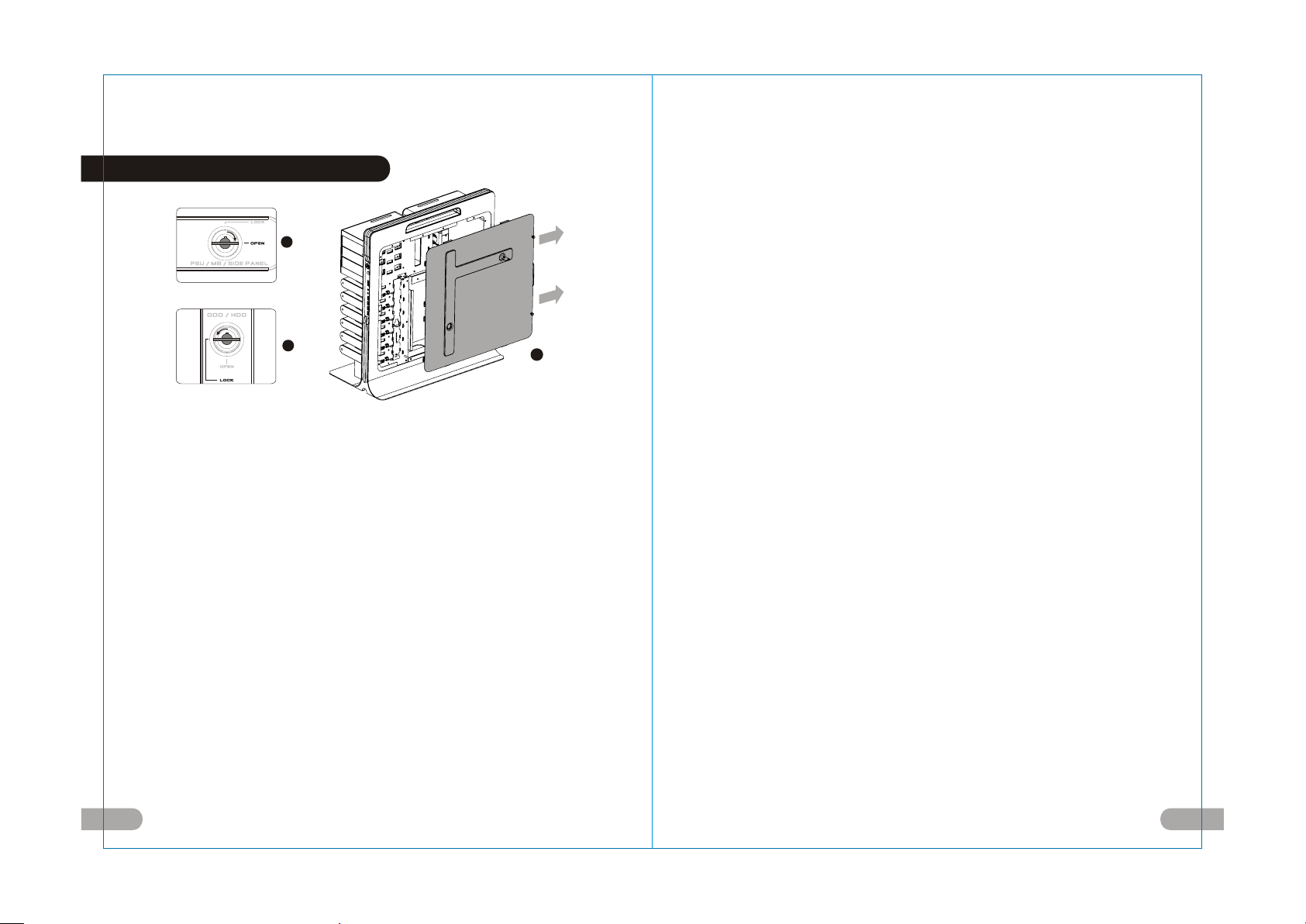
English /
1.Turn the keyhole of the side panel PSU/
MB/SIDE PANEL into the OPEN position
using the key.
2.Turn the keyhole of the side panel ODD/
HDD back into the LOCK position using
the key.
3.Unscrew the upper and lower thumbscrews
on the back of the side panel of the chassis,
and slide out the plate to open it .
Deutsche /
1. Drehen Sie die Schlüsselaufnahme an der
Seite des Gehäuses mithilfe des Schlüssels
in die Position PSU//MB/SIDE PANEL.
2. Drehen Sie die Schlüsselaufnahme der
Seitentafel ODD/HDD mit dem Schlüssel
zurück in die Position LOCK.
3. Lösen Sie die oberen und unteren
Flügelschrauben auf der Rückseite der
Seitentafel des Gehäuses und schieben
Sie die Seitenabdeckung nach auswärts,
um sie zu öffnen.
Français /
1. Tournez la boutonnière du panneau latéral
BLOC D’ALIMENTATION/CARTE MERE/
PANNEAU LATERAL dans la position
OUVERTE à l’aide de la clé.
2. Tournez la boutonnière du panneau latéral
LECTEUR OPTIQUE/DISQUE DUR dans la
position VERROUILLEE à l’aide de la clé.
3. Dévissez les vis à serrage à main
supérieure et inférieure situées au dos du
panneau latéral du châssis, puis faites
glisser le panneau pour l’ouvrir.
Español /
1. Gire la cerradura del panel lateral PSU/
MB/SIDE PANEL a la posición OPEN
utilizando la llave.
2. Gire de nuevo la cerradura del panel
lateral ODD/HDD a la posición LOCK
utilizando la llave.
3. Desatornille los tornillos de mano superior e
inferior de la parte trasera del panel lateral de
la carcasa y deslice la placa para abrirla.
繁體中文 /
1.用鑰匙將側板PSU/MB/SIDE PANEL
鎖孔轉至OPEN位置.
2.用鑰匙將側板ODD/HDD鎖孔轉回
LOCK位置.
3.移除機殼側板後方上面及下面的拇指
螺絲,向外滑動開啟側板.
简体中文 /
1. 用钥匙将侧板PSU/MB/SIDE PANEL锁孔
转至OPEN位置.
2. 用钥匙将侧板ODD/HDD锁孔转回LOCK
位置.
3. 移除机壳侧板后方上面及下面的拇指螺丝,
向外滑动开启侧板.。
5 6
Page 5
2.2 Motherboard Installation
Español /
1. Gire la cerradura del panel lateral PSU/MB/
1
2
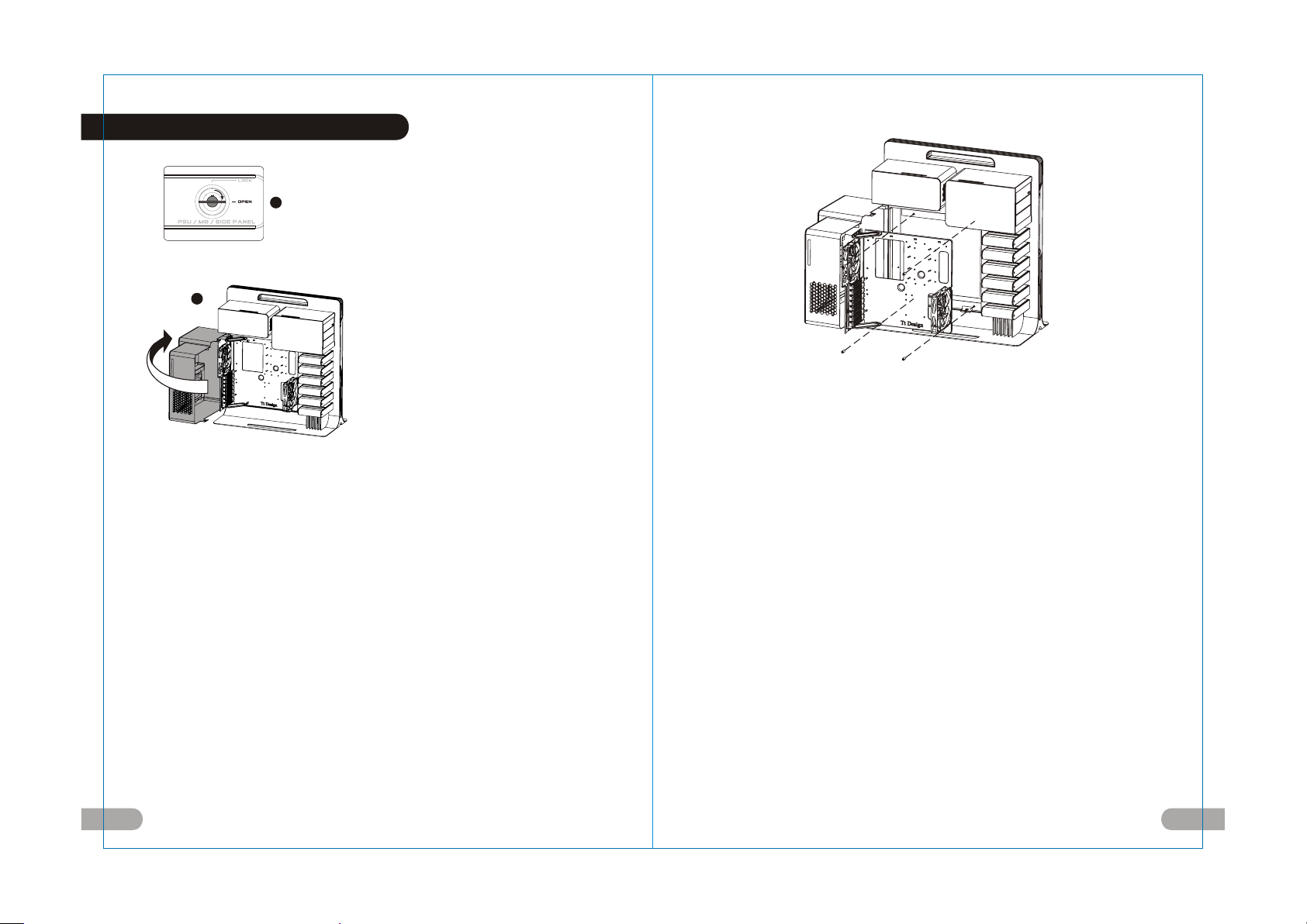
English /
1.Turn the keyhole of the side panel PSU/
MB/SIDE PANEL into the OPEN position
using the key.
2.Open the motherboard cover.
Deutsche /
1. Drehen Sie die Schlüsselaufnahme an
der Seite des Gehäuses PSU/MB/SIDE
PANEL mithilfe des Schlüssels in die
Position OPEN.
2. Öffnen Sie die Hauptplatinenabdeckung.
Français /
1. Tournez la boutonnière du panneau
latéral BLOC D’ALIMENTATION/CARTE
MERE/PANNEAU LATERAL dans la
position OUVERTE à l’aide de la clé.
2. Ouvrez le couvercle de la carte mère.
7 8
SIDE PANEL a la posición OPEN utilizando
la llave.
2. Abra la cubierta de la placa madre.
Italiano /
1. Ruotare l'incavo per la chiavetta del
pannello laterale PSU/MB/SIDE PANEL in
posizione OPEN (APERTO) usando la chiave.
2. Aprire la copertura della scheda madre.
繁體中文 /
1.用鑰匙將側板PSU/MB/SIDE PANEL鎖孔
轉至OPEN位置.
2.轉開主機板裝置外蓋.
简体中文 /
1. 用钥匙将侧板PSU/MB/SIDE PANEL锁孔转
至OPEN位置.
2. 转开主机板装置外盖.
日本語 /
1. キーを使って、側面パネルのPSU/MB/SIDE
PANELのキー穴を「開放」位置まで回します.
2. マザーボードカバーを開けます.
Русский /
1. 4. Поверните отверстие под ключ на
боковой панели PSU/MB/SIDE PANEL
(БП/МП/БОКОВАЯ ПАНЕЛЬ) в положение
OPEN (ОТКРЫТО) с помощью ключа.
2. Откройте крышку материнской платы.
Türkçe /
1. Anahtarı kullanarak yan panelin PSU/MB/
SIDE PANEL deliğini OPEN (açık)
konuma getirin.
2. Anakart kapağını açın.
English /
3. Unscrew the four thumbscrews from the
motherboard tray.
Deutsche /
3. Entfernen Sie die vier Flügelschrauben
vom Hauptplatinenschacht.
Français /
3. Dévissez les quatre vis à serrage à main
du plateau de la carte mère.
Español /
3. Desatornille los cuatro tornillos de mano
de la bandeja de la placa madre.
Italiano /
3. Svitare le quattro viti ad aletta dal
vano della scheda madre.
繁體中文 /
3. 取下主機板拖盤上的四顆拇指螺絲.
简体中文 /
3. 取下主机板拖盘上的四颗拇指螺丝.
日本語 /
3. マザーボードトレイから4本の蝶ね
じを外します.
Русский /
3. Открутите четыре винта с
накатанной головкой из лотка для
материнской платы.
Türkçe /
3. Anakart tepsisindeki dört kelebek
vidayı gevşetin.
Page 6
Italiano /
4. Mettere la scheda madre in posizione e
fissarla con le viti e i cilindri in rame.
5. Posizionare il vano della scheda madre
all’interno e avvitare le quattro viti
ad aletta.
Italiano /
6. Posizionare il coperchio della scheda
madre.
7. Ruotare di nuovo l'incavo per la
6
chiavetta del pannello laterale PSU/
MB/SIDE PANEL in posizione LOCK
(BLOCCO) usando la chiave.
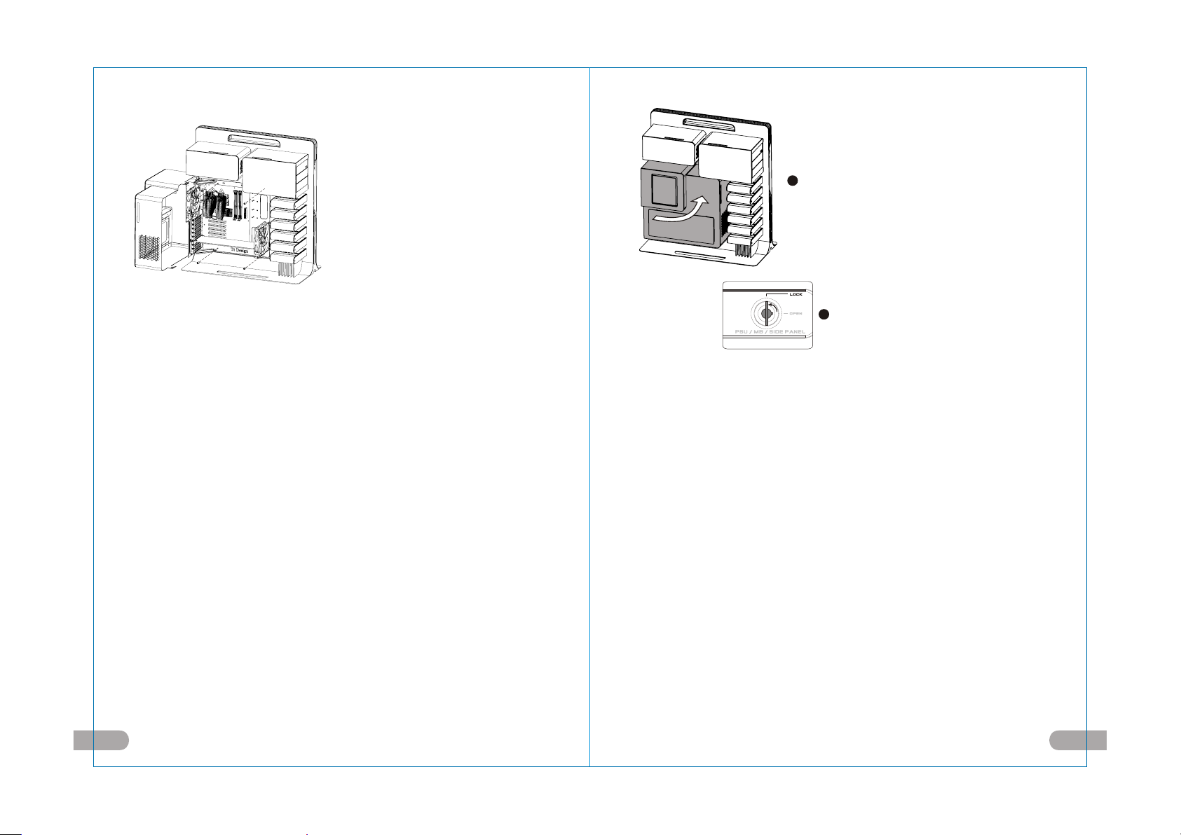
English /
4. Put the motherboard in place and fix it
with the copper cylinders and screws.
5. Place the motherboard tray back inside
and screw the four thumbscrews.
Deutsche /
4. Bringen Sie die Hauptplatine in Position
und fixieren Sie sie mit den
Kupferzylindern und Schrauben.
5. Bringen Sie den Hauptplatinenschacht
wieder auf der Innenseite an und ziehen
Sie die vier Flügelschrauebn fest.
Français /
1. Placez la carte mère puis fixez-la à l’aide
des cylindres en cuivre et des vis.
2. Replacez le plateau de la carte mère à
l’intérieur puis vissez les quatre vis à
serrage à main.
Español /
4. Coloque la placa madre en su sitio y
fíjela con los tornillos y cilindros de cobre.
5. Coloque otra vez la bandeja de la placa
madre en el interior y atornille los cuatro
tornillos de mano.
繁體中文 /
1.將主機板放置在適合的位置並用銅柱與螺
絲固定.
2.放回主機板拖盤並鎖上四顆拇指螺絲.
简体中文 /
4. 将主机板放置在适合的位置并用铜柱与
螺丝固定.
5. 放回主机板拖盘并锁上四颗拇指螺丝.
日本語 /
4. マザーボードを所定の位置に置き、銅シ
リンダーとねじで固定します.
5. マザーボードトレイを中に戻し、4本の蝶
ねじで締め付けます.
Русский /
4. Установите материнскую плату на
место и закрепите ее медными
цилиндрами и винтами.
5. Установите лоток для материнской
платы в корпус и закрепите его
четырьмя винтами накатанной головкой.
Türkçe /
4. Anakartı yerine yerleştirin ve bakır
silindirleri ve vidaları kullanarak sabitleyin.
5. Anakart tepsisini tekrar içeri yerleştirin
ve dört kelebek vidayı sıkıştırın.
7
English /
6. Put the motherboard cover in place.
7. Turn the keyhole of the side panel
PSU/MB/SIDE PANEL back into the
LOCK position using the key.
Deutsche /
6. Bringen Sie die Hauptplatinenabdeckung
wieder an.
7. Drehen Sie die Schlüsselaufnahme an
der Seite des Gehäuses PSU/MB/SIDE
PANEL wieder mithilfe des Schlüssels in
die Position LOCK.
Français /
6. Replacez le couvercle de la carte mère.
7. Tournez la boutonnière du panneau
latéral BLOC D’ALIMENTATION/CARTE
MERE/PANNEAU LATERAL dans la
position VERROUILLEE à l’aide de la clé.
Español /
6. Coloque en su sitio la cubierta de la
placa madre.
7. Gire de nuevo la cerradura del panel
lateral PSU/MB/SIDE PANEL a la
posición LOCK utilizando la llave.
繁體中文 /
6. 關上主機板裝置外蓋.
7. 用鑰匙將側板PSU/MB/SIDE PANEL鎖
孔轉回LOCK位置.
简体中文 /
6. 关上主机板装置外盖.
7. 用钥匙将侧板PSU/MB/SIDE PANEL锁
孔转回LOCK位置.
日本語 /
6. マザーボードカバーを所定の位置に置
きます.
7. キーを使って、側面パネルのPSU/MB/
SIDE PANELのキー穴を「ロック」
位置まで戻します.
Русский /
6. Установите крышку материнской
платы на место.
7. Поверните отверстие под ключ на
боковой панели PSU/MB/SIDE PANEL
(БП/МП/БОКОВАЯ ПАНЕЛЬ) обратно
в положение LOCK (БЛОКИРОВКА) с
помощью ключа.
Türkçe /
6. Anakart kapağını yerine yerleştirin.
7. Anahtarı kullanarak yan panelin PSU/
MB/SIDE PANEL deliğini LOCK (kilitli)
konuma getirin.
9 10
Page 7
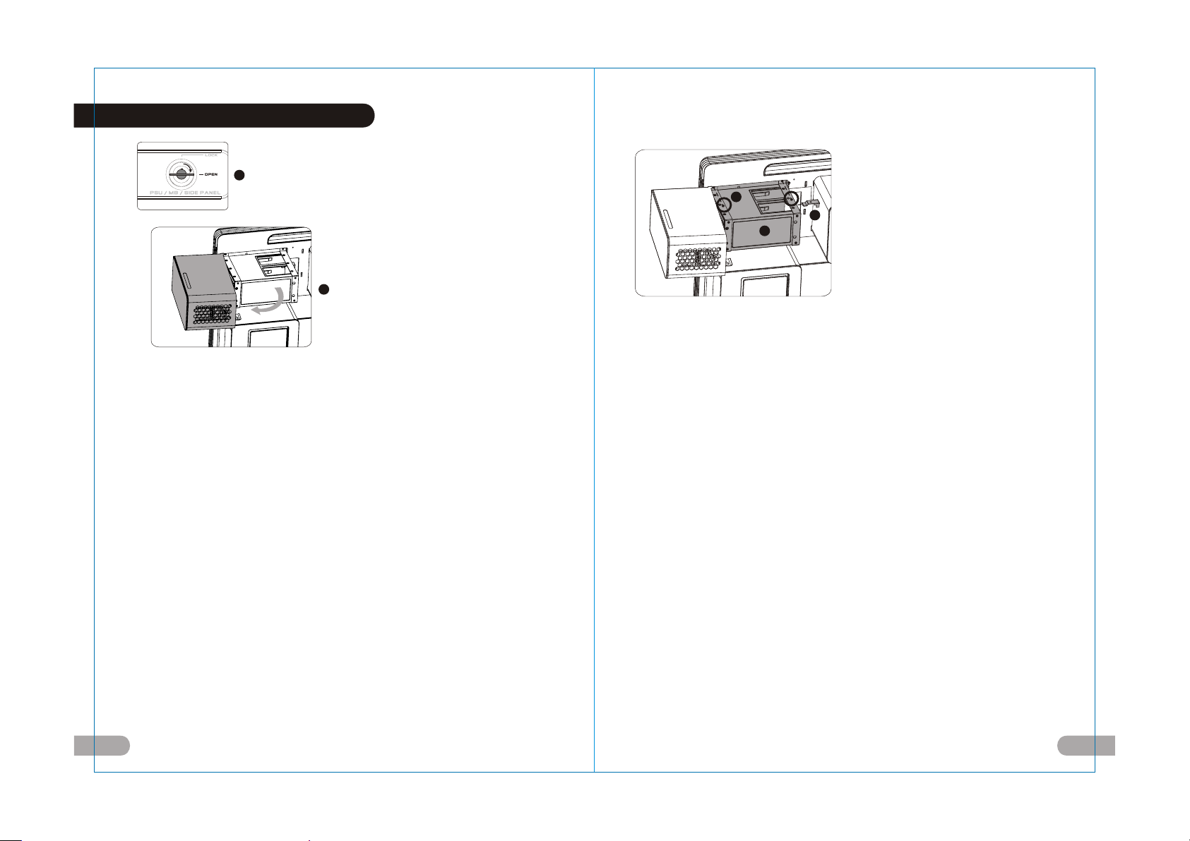
2.3 Power Supply Installation
1
2
English /
1.Turn the keyhole of t he side panel
PSU/MB/SIDE PANEL into the OPEN
position using the key.
2.Open the power supply cover.
Deutsche /
1. Drehen Sie die Schlüsselaufnahme an der
Seite des Gehäuses PSU/MB/SIDE PANEL
mithilfe des Schlüssels in die
Position OPEN.
2. Öffnen Sie die Netzteilabdeckung.
Français /
1. Tournez la boutonnière du panneau latéral
BLOC D’ALIMENTATION/CARTE MERE/
PANNEAU LATERAL dans la position
OUVERTE à l’aide de la clé.
2. Ouvrez le couvercle du bloc d’alimentation.
Español /
1. Gire la cerradura del panel lateral PSU/MB/
SIDE PANEL a la posición OPEN
utilizando la llave.
2. Abra la cubierta de la fuente de
alimentación.
Italiano /
1. Ruotare l'incavo per la chiavetta del
pannello laterale PSU/MB/SIDE PANEL
in posizione OPEN (APERTO) usando la
chiave.
2. Aprire il coperchio dell’alimentatore.
繁體中文 /
1. 用鑰匙將側板PSU/MB/SIDE PANEL
鎖孔轉至OPEN位置.
2. 轉開電源供應器裝置外蓋.
简体中文 /
1. 用钥匙将侧板PSU/MB/SIDE PANEL锁孔
转至OPEN位置.
2. 转开电源供应器装置外盖.
日本語 /
1. キーを使って、側面パネルのPSU/MB/
SIDE PANELのキー穴を「開放」位置ま
で回します.
2. 電源装置カバーを開けます.
Русский /
1. Поверните отверстие под ключ на
боковой панели PSU/MB/SIDE PANEL
(БП/МП/БОКОВАЯ ПАНЕЛЬ) в
положение OPEN (ОТКРЫТО) с
помощью ключа.
2. Откройте крышку блока питания.
Türkçe /
1. Anahtarı kullanarak yan panelin PSU/MB/
SIDE PANEL deliğini OPEN (açık)
konuma getirin.
2. Güç kaynağı kapağını açın.
3
5
4
English /
3. Unscrew the two screws from the
power supply holder using the
screwdriver.
4. Remove the holder along the hooks.
5. Remove the stops from the holder.
Deutsche /
3. Lösen Sie die zwei Schrauben vom
Netzteilhalter mit einem
Schraubendreher.
4. Entfernen Sie den Halter an den
Aufhängungen.
5. Entfernen Sie die Stopper vom Halter.
Français /
3. Dévissez les deux vis du support du bloc
d’alimentation à l’aide du tournevis.
4. Retirez le support le long des crochets.
5. Retirez les butoirs du support.
Español /
3. Desatornille los dos tornillos del
soporte de la fuente de alimentación
con un destornillador.
4. Retire el soporte a lo largo de los
ganchos.
5. Retire los topes del soporte.
Italiano /
3. Svitare le due viti dal supporto
dell’alimentatore utilizzando il
cacciavite.
4. Rimuovere il supporto lungo i ganci.
5. Rimuovere i fermi dal supporto.
繁體中文 /
3. 用螺絲起子卸下電源供應器支架上兩顆
螺絲.
4. 將電源供應器支架沿卡勾處取下.
5. 取下電源供應器支架上之固定檔片.
简体中文 /
3. 用螺丝起子卸下电源供应器支架上两颗
螺丝.
4. 将电源供应器支架沿卡勾处取下.
5. 取下电源供应器支架上之固定档片.
日本語 /
3. ドライバーを使って、電源装置のホルダ
ーから2本のねじを外します.
4. フックに沿ってホルダーを取り外します.
5. ホルダーから止め具を取り外します.
Русский /
3. Открутите отверткой два винта из
держателя блока питания.
4. Снимите держатель с крючков.
5. Извлеките ограничители из
держателя.
Türkçe /
3. Tornavida kullanarak güç kaynağı
tutucusundaki iki vidayı gevşetin.
4. Tutucuyu kancalar hizasından çıkartın.
5. Tutucudaki tamponları çıkartın.
11 12
Page 8

Italiano /
8. Fissare correttamente l’alimentatore.
9. Posizionare il coperchio dell’alimentatore.
10. Ruotare di nuovo l'incavo per la chiavetta
6
7
Italiano /
8
9
6. Posizionare l’alimentatore e fissarlo
con le viti.
7. Bloccare i fermi sul supporto.
del pannello laterale PSU/MB/SIDE
PANEL in posizione LOCK (BLOCCO)
usando la chiave.
繁體中文 /
8. 將電源供應器鎖回.
9. 將電源供應器外蓋蓋上.
10. 用鑰匙將側板PSU/MB/SIDE PANEL
鎖孔轉回LOCK位置.
10
繁體中文 /
English /
6.Put the power supply in place and fix
it with the screws.
7.Lock the stops onto the holder.
Deutsche /
6. Bringen Sie das Netzteil in Position und
fixieren Sie es mit den Schrauben.
7. Befestigen Sie die Stopper am Halter.
Français /
6. Positionnez le bloc d’alimentation puis
fixez-la avec les vis.
7. Verrouillez les butoirs sur le support.
Español /
6. Coloque la fuente de alimentación en
su sitio y fíjela con los tornillos.
7. Fije los topes en el soporte.
6. 將電源供應器裝入並鎖上螺絲固定.
7. 鎖回電源供應器支架檔片.
简体中文 /
6. 将电源供应器装入并锁上螺丝固定.
7. 锁回电源供应器支架档片.
日本語 /
6. 電源装置を所定の位置に置き、ねじで
固定します.
7. 止め具をホルダー上にロックします.
Русский /
6. Установите блок питания на место и
закрепите его винтами.
7. Зафиксируйте ограничители в
держателе.
Türkçe /
6. Güç kaynağını yerine yerleştirin ve
vidalarla sabitleyin.
7. Tamponları tutucunun üzerine takın.
English /
8. Fix the power supply properly.
9. Put the power supply cover in place.
10. Turn the keyhole of the side panel PSU/
MB/SIDE PANEL back into the LOCK
position using the key.
Deutsche /
8. Fixieren Sie das Netzteil.
9. Bringen Sie die Netzteilabdeckung an.
10. Drehen Sie die Schlüsselaufnahme an der
Seite des Gehäuses PSU/MB/SIDE PANEL
wieder mithilfe des Schlüssels in die
Position LOCK.
Français /
8. Fixez fermement le bloc d’alimentation.
9. Replacez le couvercle du bloc d’alimentation.
10. Tournez la boutonnière du panneau
latéral BLOC D’ALIMENTATION/CARTE
MERE/PANNEAU LATERAL dans la
position VERROUILLEE à l’aide de la clé.
Español /
8. Fije adecuadamente la fuente de
alimentación.
9. Coloque en su sitio la cubierta de la fuente
de alimentación.
10. Gire de nuevo la cerradura del panel
lateral PSU/MB/SIDE PANEL a la posición
LOCK utilizando la llave.
简体中文 /
8. 将电源供应器锁回.
9. 将电源供应器外盖盖上.
10. 用钥匙将侧板PSU/MB/SIDE PANEL锁孔
转回LOCK位置.
日本語 /
8. 電源装置を適切に固定します.
9. 電源装置を所定の位置に置きます.
10. キーを使って、側面パネルのPSU/MB/
SIDE PANELのキー穴を「ロック」位置
まで戻します.
Русский /
8. Закрепите блок питания
надлежащим образом.
9. Установите крышку блока питания
на место.
10. Поверните отверстие под ключ на
боковой панели PSU/MB/SIDE
PANEL (БП/МП/БОКОВАЯ ПАНЕЛЬ)
обратно в положение LOCK
(БЛОКИРОВКА) с помощью ключа.
Türkçe /
8. Güç kaynağını uygun biçimde sabitleyin.
9. Güç kaynağı kapağını yerine yerleştirin.
10. Anahtarı kullanarak yan panelin PSU/
MB/SIDE PANEL deliğini LOCK (kilitli)
konuma getirin.
13 14
Page 9

2.4 5.25” Device Installation
Italiano /
1
English /
1.Turn the keyhole of the side panel ODD/
HDD into the OPEN position using the key.
2.Open the cover of the 5.25” device and
remove it.
Deutsche /
1. Drehen Sie die Schlüsselaufnahme der
Seitentafel ODD/HDD mit dem Schlüssel
in die Position OPEN.
2. Öffnen Sie die 5,25” Einheit und
entfernen Sie sie.
Français /
1. Tournez la boutonnière du panneau
latéral LECTEUR OPTIQUE/DISQUE
DUR dans la position OUVERTE à l’aide
de la clé.
2. Ouvrez le couvercle du périphérique
5,25” puis retirez-le.
Español /
1. Gire la cerradura del panel lateral ODD/
HDD a la posición OPEN utilizando
la llave.
2. Abra la cubierta del dispositivo de 5,25''
y extráigalo.
15 16
1. Ruotare l'incavo per la chiavetta del
pannello laterale ODD/HDD in posizione
OPEN (APERTO) usando la chiave.
2. Aprire il coperchio del dispositivo da
5,25” e rimuoverlo.
繁體中文 /
1. 用鑰匙將側板ODD/HDD鎖孔轉開至
OPEN位置.
2
2. 轉開5.25”裝置外蓋並取下5.25”裝置外蓋.
简体中文 /
1. 用钥匙将侧板ODD/HDD锁孔转开至
OPEN位置.
2. 转开5.25”装置外盖并取下5.25”装置外盖.
日本語 /
1. キーを使って、側面パネルのODD/HDDの
キー穴を「開放」位置まで回します.
2. 5.25”デバイスのカバーを開け、デバイス
を取り外します.
Русский /
1. Поверните отверстие под ключ на
боковой панели ODD/HDD (ОД/ЖД) в
положение OPEN (ОТКРЫТО) с
помощью ключа.
2. Откройте крышку 5,25-дюймового
устройства и снимите ее.
Türkçe /
1. Anahtarı kullanarak yan panelin ODD/
HDD deliğini OPEN (açık) konuma getirin.
2. 5.25” cihazın kapağını açın ve
cihazı çıkartın.
1
2
English /
3. Remove the side panel under the
instructions for Side Panel
Disassembly.
Deutsche /
3. Entfernen Sie die Seitentafel
entsprechend den Instruktionen für die
Seitentafeldemontage.
Français /
3. Retirez le panneau latéral en suivant les
instructions de la section Désassemblage
du panneau latéral.
Español /
3. Retire el panel lateral según se
especifica en las instrucciones de
desmontaje del panel lateral.
Italiano /
3. Rimuovere il pannello laterale seguendo
le istruzioni per lo smontaggio del
pannello laterale.
3
繁體中文 /
3. 依照Side Panel Disassembly方式取下側板.
简体中文 /
3. 依照Side Panel Disassembly方式取下侧板.
日本語 /
3. 側面パネルの分解については、指示に従って
側面パネルを取り外してください.
Русский /
3. Снимите боковую панель в соответствии
с инструкциями по разборке боковой
панели.
Türkçe /
3. Yan Panelin Sökülmesi için talimatlara
uyarak yan paneli çıkartın.
Page 10

Device Group 1
(Pleas e screw at rear sc rew hole)it
English /
4. Insert the 5.25” device into the slot and
screw the device.
Deutsche /
4. Setzen Sie die 5,25” Einheit in den
Schacht ein und befestigen Sie die
Einheit mit Schrauben.
Français /
4. Insérez le périphérique 5,25” dans le slot
puis fixez le périphérique à l’aide des vis.
Español /
4. Inserte el dispositivo de 5,25'' en la
ranura y atorníllelo.
Italiano /
4. Inserire il dispositivo da 5,25” nello slot
e avvitare il dispositivo.
繁體中文 /
4. 將5.25”裝置插入插槽並用螺絲鎖上.
简体中文 /
4. 将5.25”装置插入插槽并用螺丝锁上.
日本語 /
4. 5.25”デバイスをスロットに差し込み、
デバイスをねじで取り付けます.
Русский /
4. Установите 5,25-дюймовое устройство
в разъем и закрепите устройство
винтом.
Türkçe /
4. 5.25” cihazı yuvasına yerleştirin ve
cihazı sıkıştırın.
English /
5. Put back the 5.25” device cover.
Deutsche /
5. Bringen Sie die Abdeckung für die
5,25” Einheit wieder an ihren Platz.
Français /
5. Replacez le couvercle du p
ériphérique 5,25”.
Español /
5. Vuelva a colocar la cubierta del
dispositivo de 5,25''.
Italiano /
5. Riposizionare il coperchio del
dispositivo da 5,25”.
繁體中文 /
5. 將5.25”裝置外蓋放回.
简体中文 /
5. 将5.25”装置外盖放回.
日本語 /
5. 5.25”デバイスカバーを元に戻します.
Русский /
5. Установите крышку 5,25-дюймового
устройства на место.
Türkçe /
5. 5.25” cihaz kapağını geri yerleştirin.
17 18
Page 11

Device Group 2 and 3
(Please screw it at front screw hole)
Italiano /
6. Dallo slot 2 o 3, svitare le viti dei fermi
del dispositvo da 5,25” usando il
cacciavite, quindi rimuovere i fermi.
繁體中文 /
6. 用螺絲起子取下2或3槽的5.25”裝置檔片
螺絲並移除檔片.
简体中文 /
6. 用螺丝起子取下2或3槽的5.25”装置文件片
English /
6. From Slot 2 or 3, unscrew the screws
from the stops of the 5.25” device using
the screwdriver, and then remove
the stops.
Deutsche /
6. Von Schacht 2 oder 3 entfernen Sie die
Schrauben vom Stopper der 5,25”
Einheit mit einem Schraubendreher und
entfernen Sie den Stopper.
Français /
6. Sur le Slot 2 ou 3, dévissez les vis des
butoirs du périphérique 5,25” à l’aide du
tournevis, puis retirez les butoirs.
Español /
6. De la ranura 2 o 3 desatornille los
tornillos de los topes del dispositivo de
5,25'' utilizando un destornillador y, a
continuación, extraiga los topes.
螺丝并移除档片.
日本語 /
6. スロット2または3から、ドライバーを使っ
て5.25”デバイスの止め具のねじを外し、
止め具を取り外します.
Русский /
6. В разъемах 2 или 3 открутите
отверткой винты из ограничителей
5,25-дюймового устройства и снимите
ограничители.
Türkçe /
6. Tornavida kullanarak Yuva 2 veya 3'teki
vidaları 5.2 5” cihaz tamponlarından
gevşetin, ve sonra tamponları çıkartın.
English /
7. Insert the 5.25” device into Slot 2 or
3 and screw the device.
Deutsche /
7. Setzen Sie die 5,25” Einheit in den
Schacht 2 oder 3 und befestigen Sie die
Einheit mit einer Schraube.
Français /
7. Insérez le périphérique 5,25” dans le
Slot 2 ou 3 puis fixez le périphérique
en serrant les vis.
Español /
7. Inserte el dispositivo de 5,25'' en la
ranura 2 o 3 y atorníllelo.
Italiano /
7. Inserire il dispositivo da 5,25” nello
Slot 2 o 3 e avvitare il dispositivo.
19 20
繁體中文 /
7. 將5.25”裝置插入2或3插槽並用螺絲鎖上.
简体中文 /
7. 将5.25”装置插入2或3插槽并用螺丝锁上.
日本語 /
7. 5.25”デバイスをスロット2または3に差
し込み、デバイスをねじで取り付けます.
Русский /
7. Установите 5,25-дюймовое
устройство в разъемы 2 или 3 и
закрепите устройство винтом.
Türkçe /
7. 5.25” cihazı Yuva 2 veya 3'e yerleştirin
ve cihazı sıkıştırın.
Page 12

9
10
English /
8. Put back the 5.25” device cover.
Deutsche /
8. Bringen Sie die Abdeckung für die
5,25” Einheit wieder an ihren Platz.
Français /
8. Replacez le couvercle du
périphérique 5,25”.
Español /
8. Vuelva a colocar la cubierta del
dispositivo de 5,25''.
繁體中文 /
8. 將5.25”裝置外蓋放回.
简体中文 /
8. 将5.25”装置外盖放回.
日本語 /
8. 5.25”デバイスカバーを元に戻します.
Русский /
8. Установите крышку 5,25-дюймового
устройства на место.
English /
9. Place the side panel back and lock it.
10.Turn the keyhole of the side panel ODD/
HDD into the OPEN position using the key.
Deutsche /
9. Bringen Sie die Seitentafel wieder an und
verschrauben Sie sie.
10. Drehen Sie die Schlüsselaufnahme der
Seitentafel ODD/HDD mit dem Schlüssel
in die Position OPEN.
Français /
9. Replacez le panneau latéral et verrouillez-le.
10. Tournez la boutonnière du panneau latéral
LECTEUR OPTIQUE/DISQUE DUR dans
la position OUVERTE à l’aide de la clé.
Español /
9. Vuelva a colocar el panel lateral y fíjelo.
10. Gire la cerradura del panel lateral ODD/
HDD a la posición OPEN utilizando
la llave.
繁體中文 /
9. 將側板裝回並鎖上.
10. 用鑰匙將側板ODD/HDD鎖孔轉開至
OPEN位置.
简体中文 /
9. 将侧板装回并锁上.
10. 用钥匙将侧板ODD/HDD锁孔转开至
OPEN位置.
日本語 /
9. 側面パネルを元に戻し、ロックします.
10. キーを使って、側面パネルのODD/HDDの
キー穴を「開放」位置まで回します.
Русский /
9. Установите боковую панель на место и
закрепите ее.
10. Поверните отверстие под ключ на
боковой панели ODD/HDD (ОД/ЖД) в
положение OPEN (ОТКРЫТО) с помощью
ключа.
Italiano /
Italiano /
8. Riposizionare il coperchio del
dispositivo da 5,25”.
Türkçe /
8. 5.25” cihaz kapağını geri yerleştirin.
9. Riposizionare il pannello laterale e bloccarlo.
10. Ruotare l'incavo per la chiavetta del
pannello laterale ODD/HDD in posizione
OPEN (APERTO) usando la chiave.
Türkçe /
9. Yan paneli geri yerleştirin ve kilitleyin.
10. Anahtarı kullanarak yan panelin ODD/HDD
deliğini OPEN (açık) konuma getirin.
21 22
Page 13

2.5 HDD Device Installation
Italiano /
1. Ruotare l'incavo per la chiavetta del
pannello laterale ODD/HDD in posizione
OPEN (APERTO) usando la chiave.
2. Estrarre il vano HDD e rimuoverlo.
繁體中文 /
2
1.用鑰匙將側板ODD/HDD鎖孔轉至
OPEN位置.
2.將硬碟拖盤向外抽出.
11
12
1
Italiano /
11. Posizionare il coperchio del dispositivo
da 5,25”.
12. Ruotare di nuovo l'incavo per la chiavetta
di PSU/MB/SIDE PANEL in posizione
LOCK (BLOCCO) usando la chiave.
繁體中文 /
11. 將5.25”裝置外蓋蓋上.
12. 用鑰匙將PSU/MB/SIDE PANEL鎖孔轉回至
LOCK位置.
简体中文 /
1. 用钥匙将侧板ODD/HDD锁孔转至
OPEN位置.
2. 将硬盘拖盘向外抽出.
日本語 /
1. キーを使って、側面パネルのODD/HDD
のキー穴を「開放」位置まで回します.
2. HDDを引っ張り出して取り外します.
Русский /
1. Поверните отверстие под ключ на
боковой панели ODD/HDD (ОД/ЖД) в
положение OPEN (ОТКРЫТО) с
помощью ключа.
2. Выдвиньте и извлеките лоток для
жесткого диска.
Türkçe /
1. Anahtarı kullanarak yan panelin ODD/
HDD deliğini OPEN (açık) konuma getirin.
2. HDD tepsisini dışarı doğru kaydırın ve
çıkartın.
English /
11. Put the 5.25” device cover in place.
12. Turn the keyhole of PSU/MB/SIDE PANEL
back into the LOCK position using the key.
Deutsche /
11. Befestigen Sie die Abdeckung der 5,25”
Einheit.
12. Bringen Sie die Schlüsselaufnahme PSU/
MB/SIDE PANEL mit dem Schlüssel in die
Position LOCK.
Français /
11. Positionnez le couvercle du périphérique
5,25”.
12. Tournez la boutonnière du panneau latéral
BLOC D’ALIMENTATION/CARTE MERE/
PANNEAU LATERAL dans la position
VERROUILLEE à l’aide de la clé.
Español /
11. Coloque en su sitio la cubierta del
dispositivo de 5,25''.
12. Gire de nuevo la cerradura del panel PSU/
MB/SIDE PANEL a la posición LOCK
utilizando la llave.
简体中文 /
11. 将5.25”装置外盖盖上.
12. 用钥匙将PSU/MB/SIDE PANEL锁孔转回至
LOCK位置.
日本語 /
11. 5.25”デバイスカバーを所定の位置に置き
ます。
12. キーを使って、PSU/MB/SIDE PANELのキ
ー穴を「ロック」位置まで戻します.
Русский /
11. Установите крышку 5,25-дюймового
устройства на место.
12. Поверните отверстие под ключ на
боковой панели PSU/MB/SIDE
PANEL (БП/МП/БОКОВАЯ ПАНЕЛЬ)
обратно в положение LOCK
(БЛОКИРОВКА) с помощью ключа.
Türkçe /
11. 5.25” cihaz kapağını yerine yerleştirin.
12. Anahtarı kullanarak PSU/MB/SIDE PANEL
deliğini tekrar LOCK (kilitli) konuma getirin.
English /
1.Turn the keyhole of the side panel ODD/
HDD into the OPEN position using the key.
2.Slide out the HDD tray and remove it.
Deutsche /
1. Drehen Sie die Schlüsselaufnahme der
Seitentafel ODD/HDD mit dem Schlüssel
in die Position OPEN.
2. Schieben Sie den HDD-Schacht heraus
und entfernen Sie ihn.
Français /
1. Tournez la boutonnière du panneau latéral
LECTEUR OPTIQUE/DISQUE DUR dans
la position OUVERTE à l’aide de la clé.
2. Faites glisser le plateau du disque dur vers
l’extérieur, puis retirez-le.
Español /
1. Gire la cerradura del panel lateral ODD/
HDD a la posición OPEN utilizando
la llave.
2. Deslice hacia afuera la bandeja del HDD
y extráigalo.
23 24
Page 14

Italiano /
3. HDD 3,5”: Posizionarlo nel vano e
bloccare l’incavo della chiavetta
laterale utilizzando le viti.
Italiano /
4. HDD 2,5”: Posizionarlo nel vano e
bloccare l’incavo della chiavetta inferiore
utilizzando le viti.
English /
3. 3.5” HDD: Place it onto the tray and
lock the side keyhole using the screws.
Deutsche /
3. 3,5” HDD: Platzieren Sie die Einheit im
Schacht und blockieren Sie die seitliche
Schlüsselaufnahme mit Schrauben.
Français /
3. Disque dur de 3,5” : Placez le disque
dur sur le plateau puis verrouillez la
boutonnière latérale à l’aide des vis.
Español /
3. HDD de 3,5 pulgadas: Colóquelo
sobre la bandeja y fije la cerradura
lateral utilizando los tornillos.
繁體中文 /
3. 3.5”硬碟:硬碟放置拖盤上並用螺絲鎖上
側邊鎖孔.
简体中文 /
3. 3.5”硬盘:硬盘放置拖盘上并用螺丝锁
上侧边锁孔.
日本語 /
3. 3.5” HDD:トレイの所定の位置に置き、
ねじを使って側面キー穴をロックします.
Русский /
3. 3,5-дюймовый жесткий диск:
установите диск в лоток и
заблокируйте боковое отверстие под
ключ винтами.
Türkçe /
3. 3.5” HDD: Tepsi üzerine yerleştirin ve
yan deliklerden vidaları kullanarak
sabitleyin.
English /
4. 2.5” HDD: Place it onto the tray and lock
the bottom keyhole using the screws.
Deutsche /
4. 2,5” HDD: Platzieren Sie die Einheit im
Schacht und blockieren Sie die seitliche
Schlüsselaufnahme mit Schrauben.
Français /
4. Disque dur de 2,5” : Placez le disque dur
sur le plateau puis verrouillez la
boutonnière à l’aide des vis.
Español /
4. HDD de 2,5 pulgadas: Colóquelo sobre
la bandeja y fije la cerradura inferior
utilizando los tornillos.
繁體中文 /
4. 2.5”硬碟:硬碟放置拖盤上並用螺絲鎖固底
部鎖孔.
简体中文 /
4. 2.5”硬盘:硬盘放置拖盘上并用螺丝锁固
底部锁孔.
日本語 /
4. 2.5”・HDD:トレイの所定の位置に置き、
ねじを使って下部キー穴をロックします.
Русский /
4. 2,5-дюймовый жесткий диск:
установите диск в лоток и
заблокируйте нижнее отверстие под к
люч винтами.
Türkçe /
4. 2.5” HDD: Tepsi üzerine yerleştirin ve alt
delikten vidaları kullanarak sabitleyin.
25 26
Page 15

1
Italiano /
5. Fare scorrere di nuovo il vano nel
5
supporto HDD.
1
6. Ruotare di nuovo l'incavo per la
chiavetta del pannello laterale
ODD/HDD in posizione LOCK
2
2
3
4
(BLOCCATO) usando la chiave.
5
English /
5. Slide the tray back into the HDD holder.
6. Turn the keyhole of the side panel ODD/
HDD back into the LOCK position using
the key.
Deutsche /
5. Schieben Sie den Schacht zurück in
den HDD-Halter
6. Drehen Sie die Schlüsselaufnahme
der Seitentafel. ODD/HDD mit dem
Schlüssel zurück in die Position LOCK.
Français /
5. Faites glisser le plateau sur le support
du disque dur.
6. Tournez la boutonnière du panneau
latéral LECTEUR OPTIQUE/DISQUE
DUR dans la position VERROUILLEE
à l’aide de la clé.
Español /
5. Deslice la bandeja nuevamente hacia
el interior del soporte del HDD.
6. Gire de nuevo la cerradura del panel
lateral ODD/HDD a la posición LOCK
utilizando la llave.
繁體中文 /
5. 將硬碟拖盤插回硬碟支架.
6
6. 用鑰匙將側板ODD/HDD鎖孔轉回
LOCK位置.
简体中文 /
5. 将硬盘拖盘插回硬盘支架.
6. 用钥匙将侧板ODD/HDD锁孔转回
LOCK位置.
日本語 /
5. トレイをHDDホルダーに押して戻します.
6. キーを使って、側面パネルのODD/
HDDのキー穴を「ロック」位置まで
戻します.
Русский /
5. Задвиньте лоток обратно в
держатель жестких дисков.
6. Поверните отверстие под ключ на
боковой панели ODD/HDD (ОД/ЖД)
обратно в положение LOCK
(БЛОКИРОВКА) с помощью ключа.
Türkçe /
5. Tepsiyi geri HDD tutucusunun içine
kaydırın.
6. Anahtarı kullanarak yan panelin ODD/
HDD deliğini tekrar LOCK (kilitli)
konuma getirin.
Engli sh /
(Note) Group 1 and 2 are designed for easy swappable pur pose; for the slots from Grou p 3 to 6, it is nec essary to
remove the sid e panel a nd install ad ditional connector s separately for power supply an d data tr ansfer.
Deuts che /
(Anmerkung) Gr uppe 1 und 2 sind f ür einfachen Austausch ausgelegt ; für die Schächte der Gruppe 3 bis 6 ist es
notwendig, die Seitentaf el zu ent fernen und se parat zus ätzliche Anschlüsse fü r Netztei l und Dat enübertragung zu
installieren.
Franç ais /
(Rema rque) Les Groupes 1 et 2 sont conçus po ur être f acilement échangeables ; pour le s slots d es Groupes 3 à 6,
il est nécessa ire de re tirer le panneau latér al et d’i nstaller les connecteu rs additi onnels séparé ment pour la source
d’ali mentation et le tra nsfert de s données.
Españ ol /
(Nota) Los gru pos 1 y 2 están dis eñados para un uso fác ilmente i ntercambiable ; para la s ranuras de los gr upos 3 a
6 es necesario extraer e l panel l ateral e inst alar cone ctores ad icionales ind ependient es para la fuente de
alime ntación y para la t ransferen cia de datos.
Itali ano /
Nota: i gruppi 1 e 2 son o progett ati per essere sostitu iti facil mente; per gli slot de i grupipi da 3 a 6, è necessa rio
rimuo vere il p annello l aterale e ins tallare d ei connettori aggiuntivi separat amente pe r l’alimentatore e il
trasferimento dati.
繁體中文 /
(備註)第1-2組為 易拆裝設計,第3-6組 插槽需拆下側板另外 安裝電源 接頭與資料傳輸接頭.
简体中文 /
(备注)第1-2组为 易拆装设计,第3-6组 插槽需拆下侧板另外 安装电源 接头与数据传输接头.
日本語 /
(注) グループ1と2は交換を簡単 にできるように設計 されています。グル ープ3~6のスロットの場合、側面パ ネルを
取り外し電 源装置とデータ転送 用の追加コネクタを 個別に取り付ける必要があり ます.
Русск ий /
(Приме чание) Гру ппы 1 и 2 предн азначены дл я облег чения з амены; для разъемо в групп 3 -6необходи мо
снять боковую панель и уст ановить дополните льные р азъе мы отде льно дл я блока питания и
перед ачи дан ных.
Türkç e /
(Not) Grup 1 ve 2 kolay değiştiril me amacı için tasa rlanmıştır; Grop 3 ila 6 yuvaları için, yan panelin ç ıkartılması ve
güç kaynağı ve veri tran sferi içi n ek bağlantılar takılması gerek lidir.
6
27 28
Page 16

2.6 PCI Slot Installation 2.7 Installation of Red LED Light
Italiano /
1. Svitare le viti e rimuovere i fermi PCI.
2. Inserire il dispositivo PCI
English /
1.Unscrew the screws and remove the PCI
stops.
2.Insert the PCI device into the PCI slot.
3.Screw the device to finish the installation.
Deutsche /
1. Lösen Sie die Schrauben und entfernen
Sie die PCI-Stopper.
2. Stecken Sie die PCI-Karte in den PCI Steckplatz.
3. Befestigen Sie die Einheit, um die
Installation zu beenden.
Français /
1. Dévissez les vis et retirez les butoirs PCI.
2. Insérez le périphérique PCI dans le
slot PCI.
3. Vissez le périphérique pour terminer
l’installation.
Español /
1. Desatornille los tornillos y extraiga los
topes del PCI.
2. Inserte el dispositivo PCI en la ranura
para el PCI.
3. Atornille el dispositivo para finalizar
la instalación.
nell’apposito slot.
3. Per terminare l’installazione, avvitare
il dispositivo.
繁體中文 /
1.鬆開螺絲取下PCI檔片.
2.插入PCI裝置於PCI插槽中.
3.鎖上螺絲完成安裝.
简体中文 /
1. 松开螺丝取下PCI檔片.
2. 插入PCI装置于PCI插槽中.
3. 锁上螺丝完成安装.
日本語 /
1. ねじを外し、PCIスロットを取り外
します.
2. PCIデバイスをPCIスロットに差し込
みます.
3. デバイスをねじで締め付け取り付け
を完了します.
Русский /
1. Открутите винты и снимите
ограничители PCI.
2. Вставьте устройство PCI в его
разъем.
3. Закрепите устройство винтом,
чтобы завершить установку.
Türkçe /
1. Vidaları gevşetin ve PCI tamponlarını
çıkartın.
2. PCI cihazını, PCI yuvasının içine
yerleştirin.
3. Takma işlemini tamamlamak için
cihazı sıkıştırın.
English /
Insert the 4-pin plug of the power supply
into the 4-pin socket on the back of the
PCB board.
Deutsche /
Stecken Sie den 4-poligen Stecker vom
Netzteil in die 4-polige Aufnahme auf der
Rückseite der PCB-Platine.
Français /
Insérez la prise à 4 broches du bloc
d’alimentation dans le socket à 4 broches
situé sur l’arrière de la carte PCB.
Español /
Inserte el conector de 4 contactos (pins) de
la fuente de alimentación en el enchufe de
4 contactos de la parte trasera de la
tarjeta PCB.
Italiano /
Inserire la spina da 4 pin dell’alimentatore
nella presa da 4 pin posta nella parte
posteriore della scheda PCB.
繁體中文 /
將電源4pin接頭插在PCB版後方4pin插座上.
简体中文 /
将电源4pin接头插在PCB版后方4pin插座上.
日本語 /
電源装置の4ピンプラグを、PCBボード背面
の4ピンソケットに差し込みます.
Русский /
Вставьте 4-контактный разъем блока
питания в 4-контактное гнездо на задней
части печатной платы.
Türkçe /
Güç kaynağının 4-pinli fişini PCB kartının
arkasındaki 4-pinli sokete yerleştirin.
29 30
Page 17

Chapter 3. Leads Installation Guide
31 32
Page 18

33 34
Page 19

Chapter 4. Other
Tou ghpo wer / Pure powe r / TR2 power suppl y seri es (op tion al)
35 36
Page 20

Me mo Me mo
Page 21

Me mo Me mo
Page 22

Me mo Me mo
 Loading...