

Page 1

TM
2006 Thermaltake Technology Co., Ltd. All Rights Reserved. 2006.12
C
Tested To Comply
With FCC Standards
FOR HOME OR OFFICE USE
All other registered trademarks belong to their respective companies.
www.thermaltake.com
VF6000 Series
Page 2
1
Chapter 1. Product Introduction
Chapter 2. Case Mechanical Operation
Specification
Chapter3 Motherboard & Leads Installation
Motherboard Installation
Case LED connections
USB 2.0 & IEEE 1394 Firewire Connection
Audio Connection
2-1
2-2
2-3
2-4
2-5
2-6
2-7
2-8
2-9
How to open the top panel
5.25" device installation
2-2-1 CD-ROM installation
2-2-2 5.25" accessory drive installation
HDD installation
2-3-1 Install HDD on the HDD rack
2-3-2 Install HDD on the side of optical drivetray
Installing 3.5" device
Installing Power Supply
Installing graphics and PCI expansion cards
Installing Coolant tubes
Installing 60mm fan
How to open the front panel
1-1
3-1
3-2
3-3
3-4
Chapter4 Other
Recommended Products
4-1
01
02
03
03
06
08
08
09
10
11
12
13
13
14
15
16
17
18
20
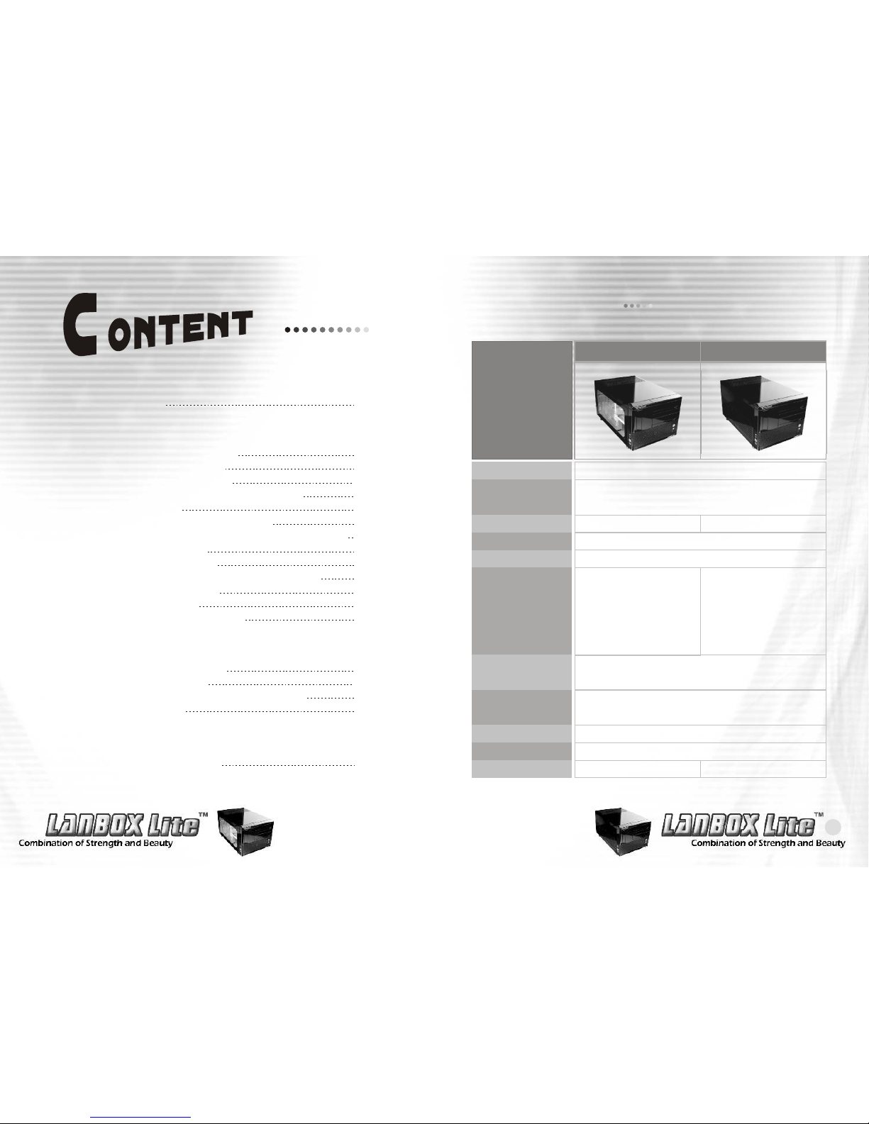
Specification
Chapter 1. Product Introduction
Model
Case Type
Dimension (W*D*H)
Window side panel
Material
Color
Cooling System
Motherboard
Drive Bays
Front I/O
Expansion Slots
Weights
VF6000BWS
Gaming Cube
Window
SECC Japanese steel
Black
-Front:
90mm fan with
blue LED x
1, 1500rpm
-Rear:
60mm fan x 2,
1800rpm
(up to 60mm fan x 3)
Micro ATX form factor & mini ITX form factor
- 5.25" x 2
- 3.5" x 3 (Exposed x 1, Hidden x 2)
USB 2.0 x 4, IEEE 1394 Firewire, HD-Audio
4
6.1 kg / 13.45 lb 6.3 kg / 13.89 lb
VF6000BNS
300 x 430 x 230 mm
11.8 X 16.9 X 9.05 inch
N/A
- Front :
90mm fan x
1, 1500rpm
- Rear :
60mm fan x
2, 1800rpm
(up to 60mm fan x 3)
s
Page 3

3
2
How to open the top panel
Chapter 2. Case Mechanical Operation
2-1
Unscrew the 3 screws shown
to open the top panel.
1
Pull back the top panel as shown to loosen the panel.
2
Unscrew the 7 screws
shown to unlock the
motherboard tray.
3
Tug on the ring and pull
back as shown to remove
the motherboard tray.
4
The motherboard tray
5
5.25" device installation
2-2
Unscrew the 2 screws as shown to slide back the
optical drive tray.
1
Pull back, then pull up to remove the optical drive tray.
2
When installing optical drives, it is recommended to screw
into the No.4 hole as shown for a flush installation.
3
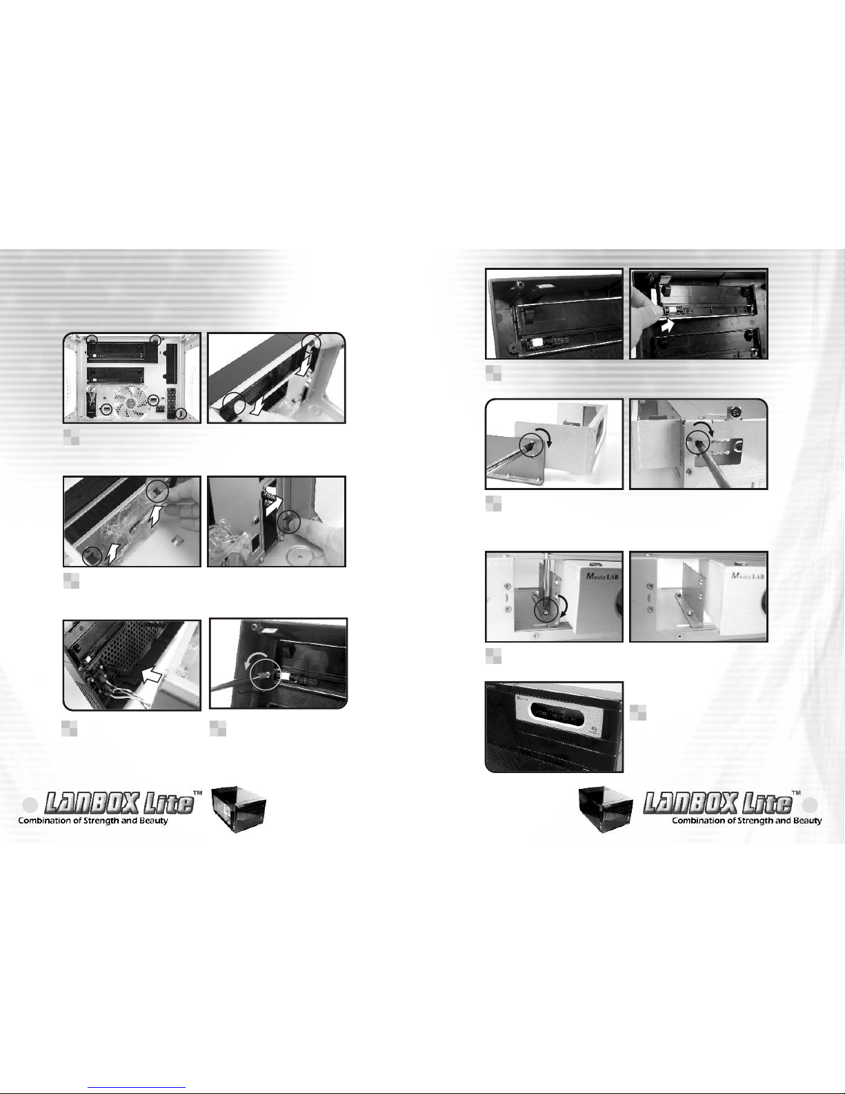
2-2-1 CD-ROM installation
Page 4

5
4
Screw in the optical drive on the opposing side.
4
When installing an optical drive on the top bay, please
install the metal adaptor first as shown.
5
Slide in the optical drive from the front.
6
Secure the optical drive on the opposing side of No.4
hole as well.
7
Secure the top optical
drive bay as shown.
8
Page 5
7
6
There are five springs in the front panel, push to release it.
1
Push and release the five springs of front panel.
2
2-2-2 5.25" accessory drive installation
When installing a 5.25" accessory drive on the top bay,
please install the metal adaptor first as shown. Screw in the
5.25" accessory drive on the opposing side of the No.5 hole.
6
Screw the top optical drive bay as shown.
7
Please make sure the 5.25"
accessory drive is flush with
the front panel.
8
After loosing the spring of
front panel, pull out it as
arrow shows.
3
Remove the 5.25" bay cover as arrow shows.
5
Unscrew the 5.25" bay
cover screw as shown.
4
Page 6

9
8
HDD installation
2-3
Unscrew the screw shown to remove the HDD rack.
1
Slide over the HDD rack
as shown to remove.
2
Secure HDDs using screws when installing in the HDD rack.
4
The HDD rack.
3
A HDD can be installed
on the side by securing
4 screws.
3
Screw in both sides of
the HDD.
4
2-3-1 Install HDD on the HDD rack 2-3-2 Install HDD on the side of optical drive tray
Unscrew the 2 screws as shown to slide back the
optical drive tray.
1
Pull back, then pull up to remove the optical drive tray.
2
Page 7

1110
Installing 3.5" device
2-4
Please make sure the
floppy drive is flush
with the front panel.
3
If a floppy drive is to be
installed, please remove
the bay cover first.
1
Secure the floppy drive using screws then screw the
opposing side as shown.
2
Installing power supply
2-5
Unscrew the 6 screws
holding in the top power
supply tray.
1
The power supply tray.
3
Install the power supply unit onto the power supply tray
as shown. If using a power supply with a 120mm fan,
please make sure the fan is exposed on the top side.
4
Lift out the power supply
tray as shown.
2
Page 8
13
12
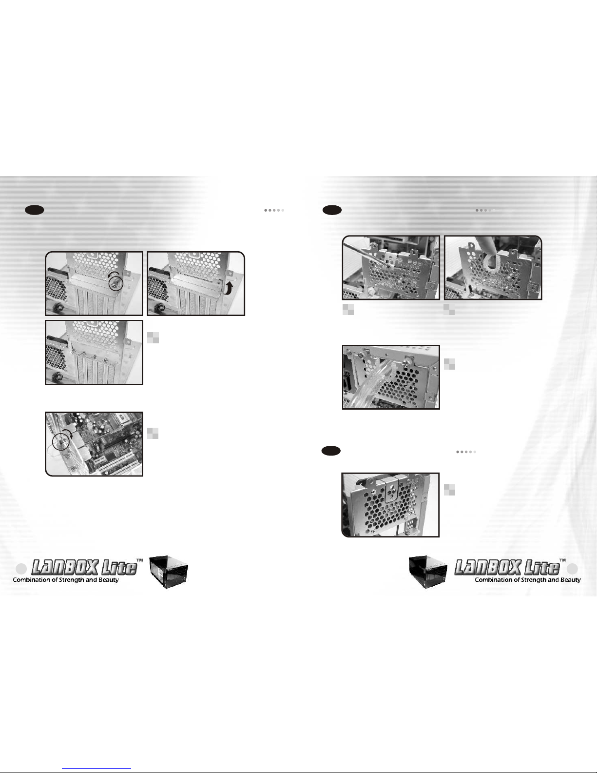
Installing graphics and PCI expansion cards
2-6
Remove the screw as
shown to install graphics
and PCI expansion cards.
1
When installing a graphic or
PCI expansion card, please
screw on the card as shown.
2
Installing coolant tubes
2-7
Installing 60mm fan
2-8
An optional 60mm fan can
be purchased and installed
on the motherboard tray
as shown.
1
If a liquid cooling system
is to be installed, please
pry off the top tab of the
motherboard tray as shown.
1
Please install the rubber
tube protector as shown.
2
Coolant tubes may be
installed as shown when
using a liquid cooling
system (optional).
3
Page 9
15
14
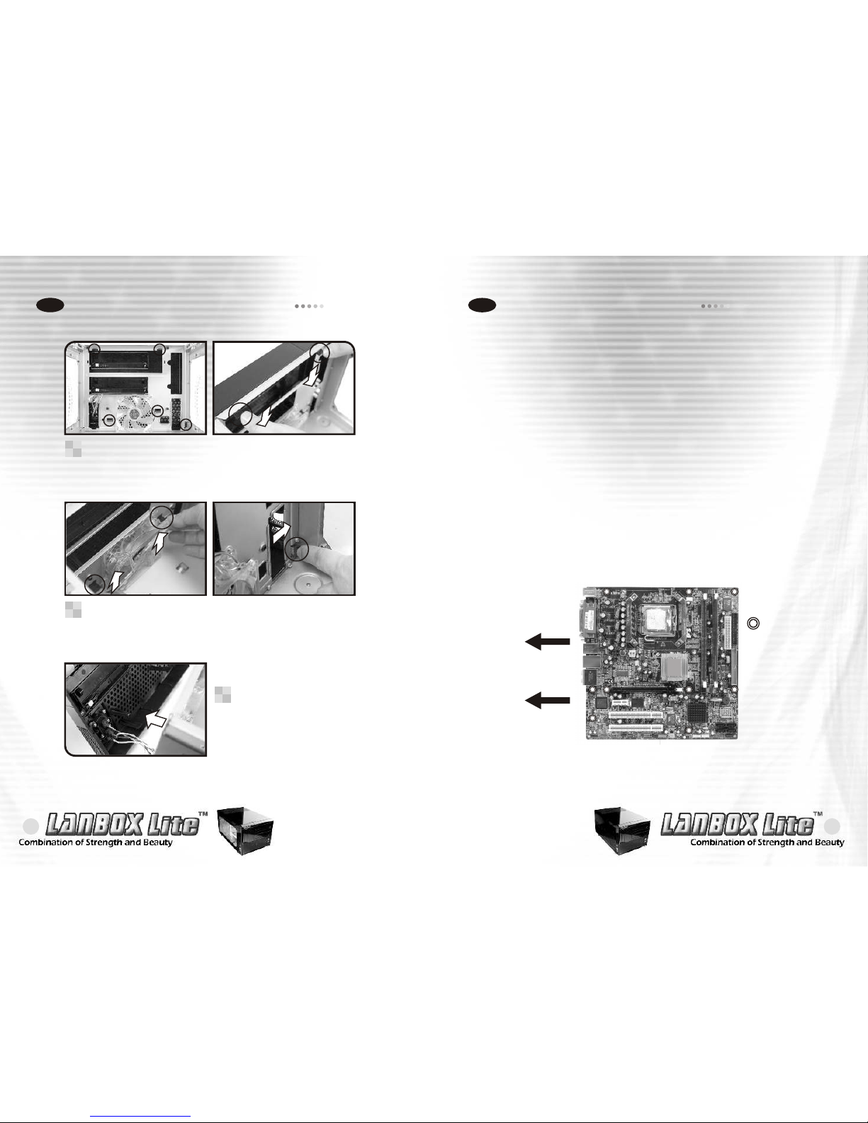
Motherboard Installation
Chapter3 Motherboard & Leads Installation
3-1
Each motherboard has different standoff layout. It is highly
suggested that you refer to your motherboard's manual when
installing motherboard into the Case. The cases are applicable
with Standard Micro ATX and mini ITX motherboards.
Your motherboard may require a special I/O Panel, which should
be included with your motherboard.
Placement Direction:
When installing the motherboard, make sure you follow the
direction provided by your motherboard manufacturer. On most
standard motherboards, the edge with external ports goes to the
rear part of the chassis. It is highly recommended that you install
CPU, heat sink and modular components before fixing the
motherboard inside the chassis.
The locations of the
screw holes. Note
these locations and
place included
standoffs on the
chassis first.
This side towards
the rear of the
chassis
Above illustration is a sample of what
the motherboard's layout. For more
detail screw hole placement, please
refer to your motherboard manual.
How to open the front panel
2-9
There are five springs in the front panel, push to release it.
1
Push and release the five springs of front panel.
2
After loosing the spring of
front panel, pull out it as
arrow shows.
3
Page 10

17
16
On the front of the case, you can find some LEDs and switch leads
(POWER SW*1, POWER LED*1, H.D.D. LED*1, RESET SW*1)
Please consult user manual of your motherboard manufacturer, then
connect these leads to the panel header on the motherboard. These
leads are usually labeled; if not, please trace them back to the case
front to find out their source.
- POWER LED connects to your M/B at the PLED
- POWER SW connects to the PWR connector on the motherboard.
- H.D.D LED connects to the eSATA connector shown as picture(3.5)
- RESET SW connects to the RSW connector on the motherboard
- SPEAKER connector: find out the 4-pin labeled SPEAKER on the
M/B then connect it.
Case LED connections
3-2
USB 2.0 & IEEE 1394 Firewire Connection
3-3
USB connection
Please consult your motherboard manual to find
out the section of "USB connection".
USB2.0
GND1
Data+1
Data-1
Vcc1
( Blank )
GND2
Data+2
Data-2
Vcc2
Page 11
19
18
IEEE1394 Firewire connection
Please consult your motherboard manual to find
out the section of "IEEE1394 Firewire connection".
IEEE 1394
VP
TPB+
VG
TPA+
SHIELD
VP
TPB-
VG
TPA-
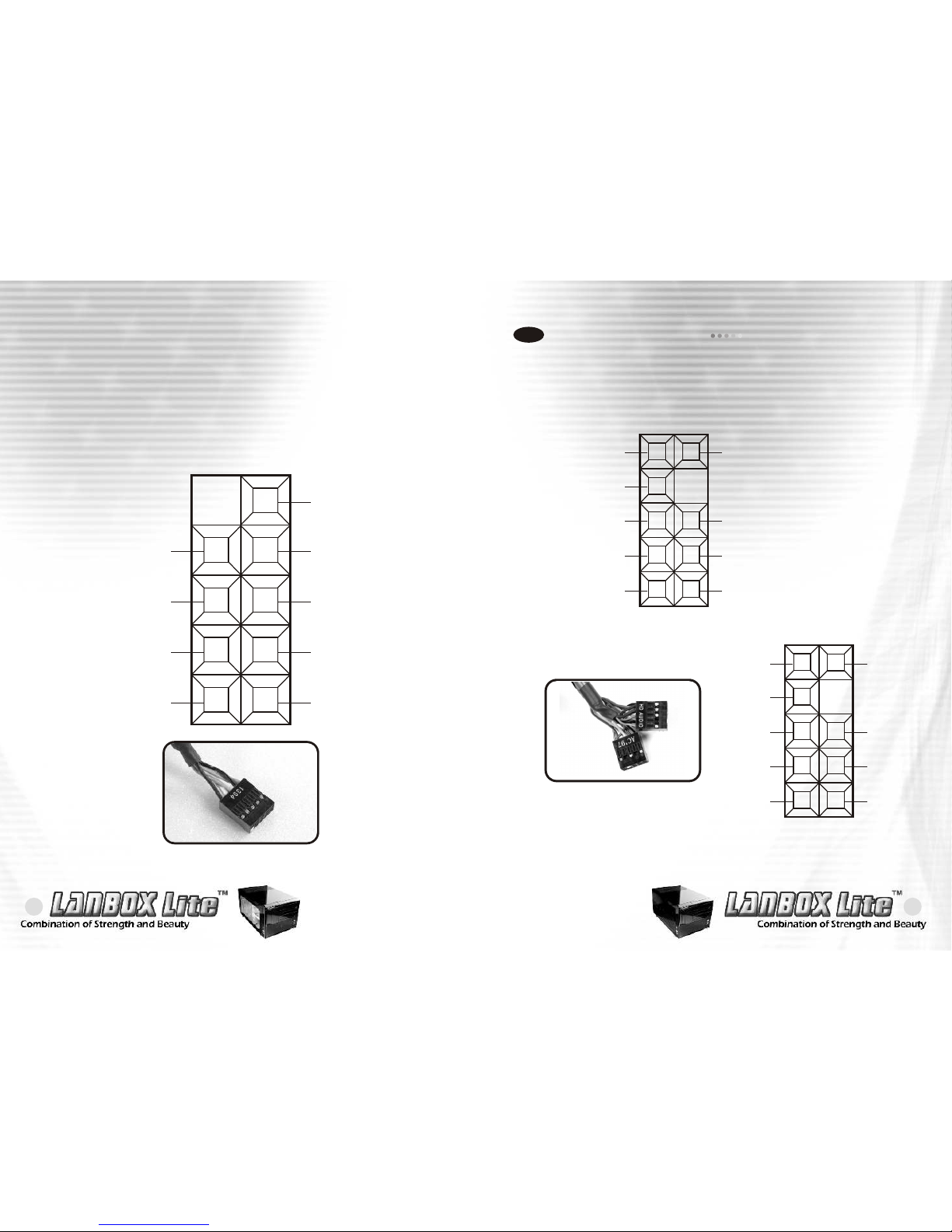
Audio Connection
3-4
Please check your motherboard ,does it support AC'97
or HD-Audio(AZALIA) , choose one of them to connect.
Splout L
( Blank )
Spekout R
MIC BIAS
MIC IN
Return L
Return R
SHIELD
GND
HD AUDIO(AZALIA)
Splout L
( Blank )
Spekout R
MIC BIAS
MIC IN
Return L
Return R
( Blank )
GND
AC'97
Page 12
21
20
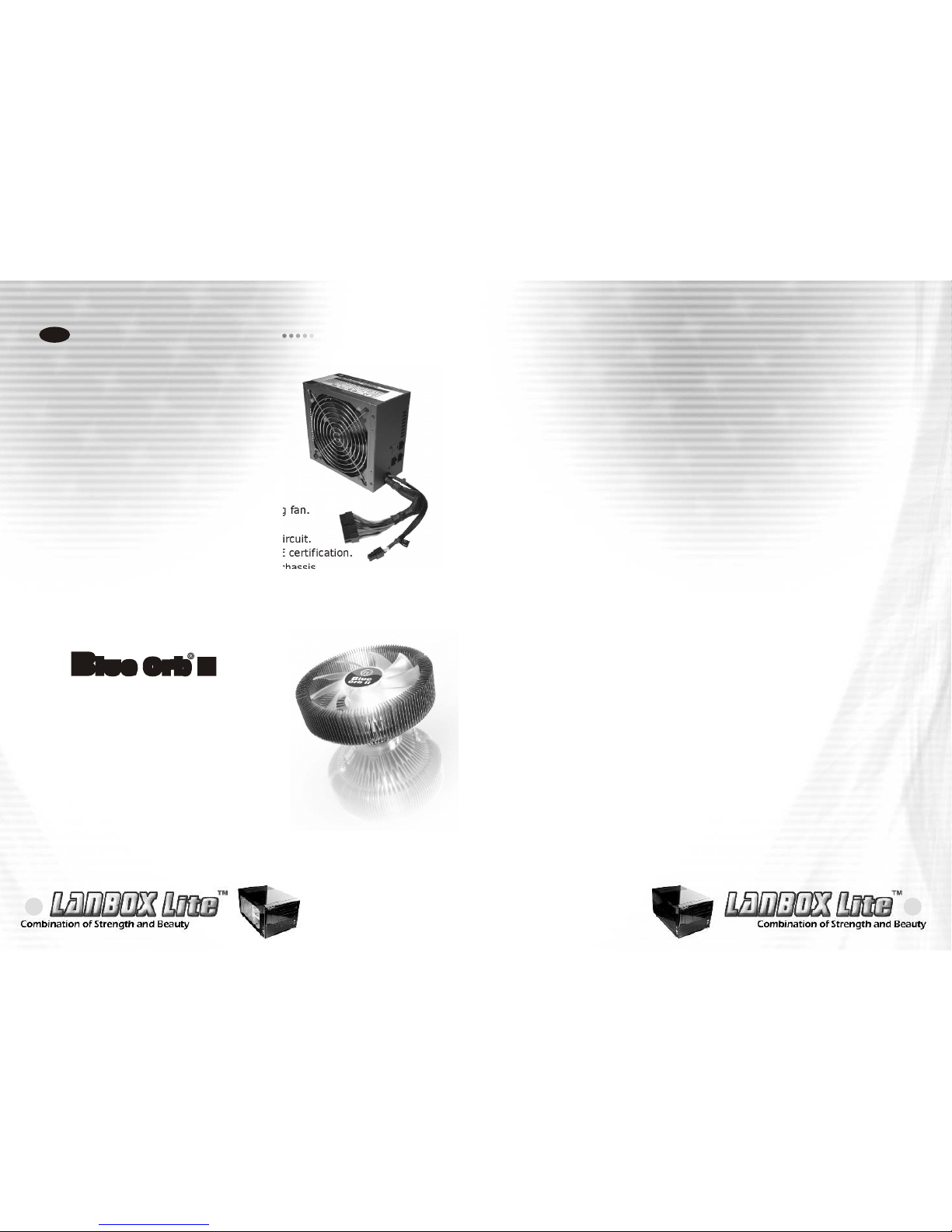
Recommended Products
4-1
- Intel ATX 12V 2.2 Compatible.
- Supports one PCI-Express, 2 S-ATA,
and 20+4 pin connector.
- Modularized Cable Management
eliminates clutter and improve airflow
inside the case.
- Super quiet and stable 14cm ball bearing fan.
- Built in industrial-grade Protections:
Over Current, Over Voltage, and Short-Circuit.
- Safety / EMI : UL, CUL, TUV, FCC and CE certification.
- Shorter cable sets reduce clutter in the chassis
- The cable length for 24pin, CPU 4pin are 300mm
and Molex, S-ATA are 200mm.
- All cables wrapped with flexible mesh.
There are recommended products of Thermaltake PSU and Cooler,
it is divided into standard, VR and specialty power supply unit.
Please refer to http://www.thermaltake.com
Chapter4 Other
Purepower 450W
P/N:W0152
Blue Orb II
P/N:CL-P0257
- Tt Patent designed Radian crotched
fin design.
- Copper core construction.
- Max.fin count:140 fins.
- Silent Blue LED fan,1700rpm, 17dBA
- Universal design for Intel Socket LGA775
& AMD Socket K8.
 Loading...