

Page 1
Pacific V-RTX 2070 Super Plus
Patented
VGA Water Block
This product is in tend ed for i nstallation only by exper t user s. Ple ase consult with a qualified tech nici an for installation. Improper i nsta llat ion may result in damage to you r equi pmen t.
Before you start u sing t his pr oduct please follow these b asic g uide lines:
1. Please carefu lly re ad thr ough the instruction manu al bef ore be ginning the installation proc ess.
2. Please remove y our gr aphi cs card from your motherboa rd to in sure t he safest process and in order to pre vent a ny possible damages to your CPU and m othe rboa rd.
3. It is strongly re comm ende d to use market proven pre-mix cool ant, s uch as Thermaltake Coolant 1000 .
16.8 Million Color
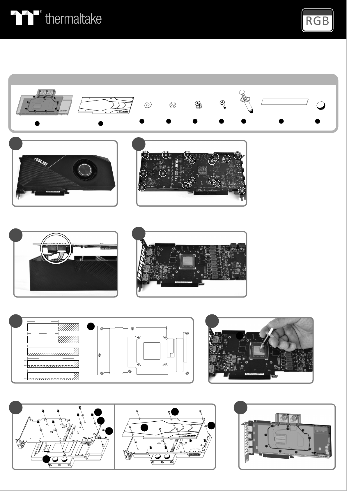
Parts List
C x 13 D x 2 E x 7 F x 6 H x 8 I x 2G x 1
2
1
A x 1
B x 1
Use RTX 2070 Super as a demonstration,
other model reference the installation guide.
3
Remove the power connector
(Carefully detach the original stock cooler)
60 mm
A
30 mm 30 mm
B B
90 mm
10mm
10mm
12mm
C
90 mm
C
90 mm
D
Remove the screws circled on the diagram.
All heat sink assembly screws should be removed.
4
Clean the original thermal compound off the GPU die
H
BCD C
A
B
65
G
Cut the thermal pads to the dimensions listed and place them on the spots shown on the diagram.
7
E
F
C
D
B
I
When installing the water block, carefully position the water block with the preinstalled standoffs
on the graphics card.
Apply thermal compound
8
C
Finish
Page 2

Pacific V-RTX 2070 Super Plus
ON
1 2 3 4
Patented
VGA Water Block
Part s List
J x 1 K x 1 L x 1 M x 1 P x 1N x 1 O x 1
Controller Power Cable
Controller Cable
Bridge Cable
LED Y - Cable MB SYNC Cable
Inst alla tion Guide
9
A
N
Connect the LED Y-Cable onto the waterblock.
10
J
N
123
Connect the Wat er bl oc k on to t he c on tr ol le r.
16.8 Million Color
Velcro
J
45
11
J
Set the DIP swi tc h on t he b ac k si de o f th e co nt ro ll er t o as si gn t he
number of the controller
12
K
K
Connect the controller cable onto the mainboard (USB 2.0 9 pin)
and controller.
13 14
NO .1
ON
1 2 3 4
NO .5
ON
1 2 3 4
NO .9
ON
1 2 3 4
NO .1 3
ON
1 2 3 4
NO .2
ON
1 2 3 4
NO .6
ON
1 2 3 4
NO .1 0
ON
1 2 3 4
NO .1 4
ON
1 2 3 4
NO .3
ON
1 2 3 4
NO .7
ON
1 2 3 4
NO .1 1
ON
1 2 3 4
NO .1 5
ON
1 2 3 4
NO .4
ON
1 2 3 4
NO .8
ON
1 2 3 4
NO .1 2
ON
1 2 3 4
NO .1 6
ON
1 2 3 4
L L
Connect the power cable to the 4pin Molex connecter and controller.
© 2019 Thermalta ke Technolog y Co. , Ltd . All Rights Re ser ved .
www.thermaltake.com
M M
If you want to connect two or more connectors, you can use the bridge
cable to connect the controllers.
 Loading...