

Page 1
1
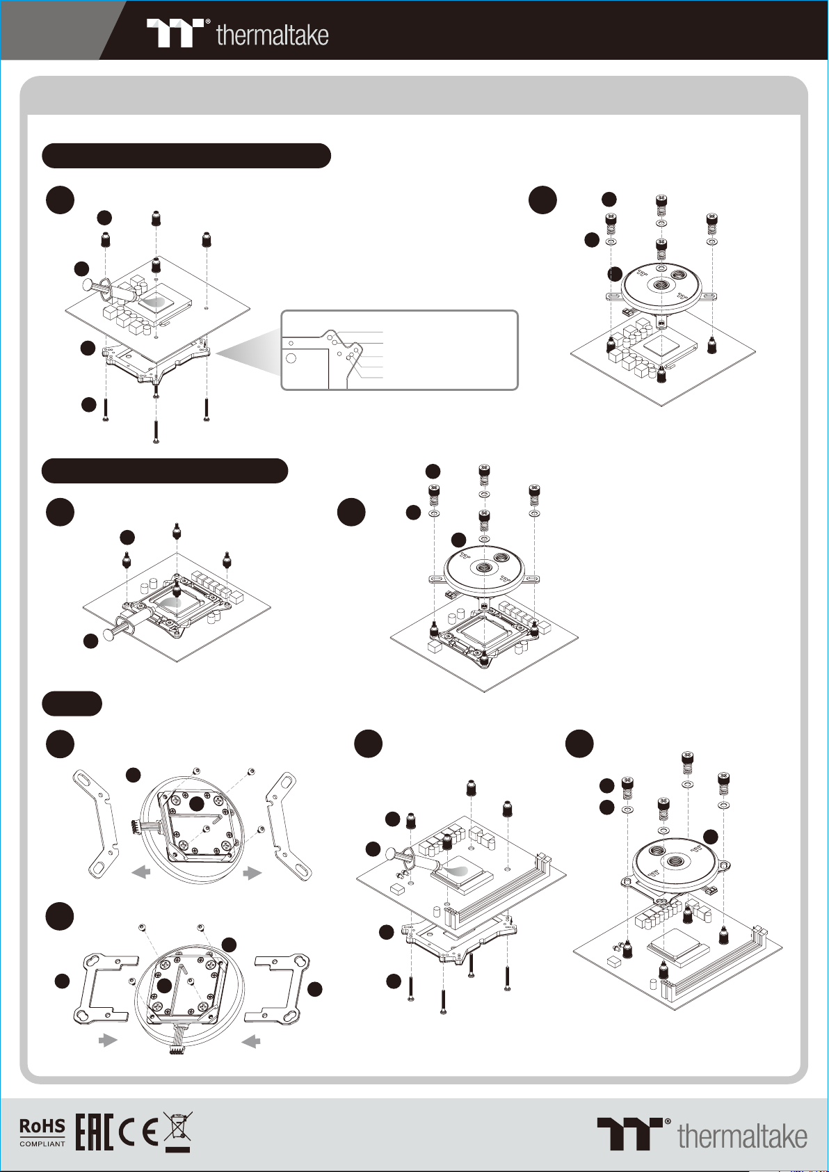
CPU Water Block Installation Guide
Intel LGA 775,LGA115x,LGA1366
PACIFIC CL360 MAX LIQUID COOLING KIT
1
06
09
03
04
Intel LGA2066,2011-3,2011
1
08
1.FM2 /F M1 /AM3/ AM 2
2.AM4
3.LGA 13 66
4.LGA 1150/1151 /115 5/ 1156
5.LGA 77 5
2
07
05
01
2
05
07
01
AMD
1
2
02
09
01
10
10
01
02
3
4
05
07
06
01
09
03
04
© 2019 Therm al take Techn ol ogy Co., Ltd. Al l Ri ghts Reserv ed .
www.therm altake.com
Page 2
2
PACIFIC CL360 MAX LIQUID COOLING KIT
Installation Guide
CAUTIONS: 1. Make sure there is enough space when you start to set up the LCS product
2. Please use the wrench to install/ uninstall the base parts during all the installation
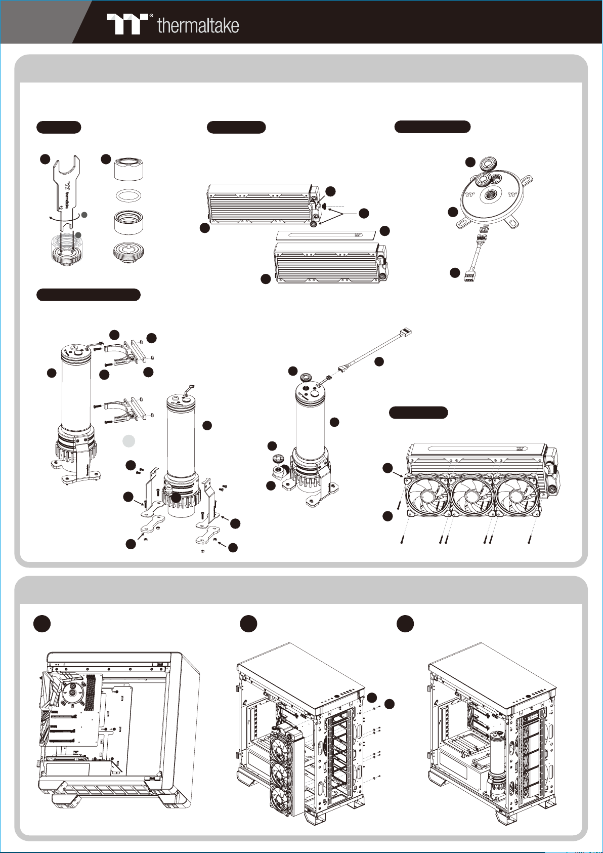
Fitting
Dism antle the fi tting by using the w rench
28 30
Nut
O- Ring
2
Packing
1
Base
Radiator
To ensure a clean loop, flush and rinse your radiators
and wa ter bl ocks w ith di stil led wa ter be fore u sing.
Make s ure th e fitt ings a re scr ewed s ecurely when
plac ing th em ont o the ra diator.
24
Pump / Reservoir
Choose the proper w ay to mount the p ump and reservoir
by referring to the m anual (suggest vertical placement)
13
12
15
14
18
12
or
29
30
Base
32
24
Attach fittings o nto the pump and reservoir
30
12
30
22
Water Block
Attach the fittin gs to the inlet a nd outlet of the
water block.
30
01
11
Case Fan
Attach the fans to the radiator
16
29
15
21
16
20
14
Installation Walkthrough (Example: A700 TG)
Place the motherb oard into the case. Position the radi ator.
1
2
23
27
Attach the pump and r eservoir into
3
the chosen locati ons.
25
26
Page 3

3
PACIFIC CL360 MAX LIQUID COOLING KIT
Cutting and Attaching the Tubing
Measure t he t ub e length ba se d on t he base
1
part of the f it ti ng, and m ak e (b end) the tu be s.
The loop or de r : Pu mp Outlet > Wate r Bl oc k
Fit the C-P ro f it ting to t he t ub e accordi ng
4 5
to the orde r in t he p icture be lo w, In stall the
tubes and t ig ht t he fittin g ca ps .
Groove
31
2
Measure t he t ub e length ba se d on t he base
part of the f it ti ng, and m ak e (b end) the tu be s.
The loop or de r : Wat er B lock > Radi at or
Finishe d
Measure t he t ub e length ba se d on t he
3
base part o f th e fi tting, an d ma ke (bend)
the tubes . The loop or de r : Ra diator >
Reservo ir i nl et
CA UT IO NCA UT IO N
The O-rin g an d th e packing
with a groo ve o n th e inside
0430
CAUTIO NS :
1. Befor e fi ll in g th e sy st em, please make
sure tha t ea ch f it ti ng a s we ll as unused
ports ar e co mp le te ly s ealed.
2. If ther e is a ny c as e of l ea ki ng,
immedi at el y tu rn o ff t he p ower and
clean th e le ak
3. If ther e is a ny r el at ed e le ctronic parts
staine d on l iq ui d co ol an t, m ake sure to
comple te ly c le an a nd d ry t he
componen ts . And then make sure they
all work wel l.
diamete r mu st a lways be
install ed t ow ards the to p of
the compr es si on nut
Filling the System
After swi tc hi ng off th e po wer suppl y,
1
connect t he P SU p ower cord a nd
product c ab le s.
34
Place you r PS U ou tside of th e ca se a nd attach i t to t he pumps 4p in m ol ex connec to r, tu rn on the
3
power of PS U an d ma ke the rest o f th e system fi ll s up .
Use the ref il l bo ttle to fil l co ol ant int o th e re servoir
2
35
Thermaltake recommends the following steps to be taken after completin g your water loop setup
1. It is s tr ongly recom mended to use m ar ket proven pr e-mix coola nt , such as Thermal ta ke Coolant 10 00. It offers great p er formanc e
whil e pr eventin g th e entire cool ing system – co pp er, brass, nic kel, alumin um , and steel – fro m corrosion .
2. Fil l th e reservo ir w ith coolant a nd c ycle the po we r on and off several ti mes while the p um p pushing t he c oolant into t he l oop.
3. DO NO T let th e pu mp run dry, when the re i s no liquid ent ering the pum p tu rn off y our power i mm ediately
4. Fil l th e reservo ir t o the top as it wil l pr event air fro m going into th e pu mp
5. If ne ce ssary tilt th e system slig ht ly from side to s ide to bleed th e ai r out of the loop .
6. Pla ce s ome paper t ow els under fit ti ngs and joi ni ng points to te st f or leaks.
7. Run t he l oop with the fi ll port open fo r ab out 24 hours to c ompletely b le ed the air out of t he loop.
Page 4

4
ON
1 2 3 4
ON
1 2 3 4
1
11
PACIFIC CL360 MAX LIQUID COOLING KIT
Installation Guide
22
40
40
23 32
Conn ect the p lug into th e port in n umerica l order,
star t with pl ug one.
2
NO.1 NO.2
Set th e DIP switch on the back s ide of the control ler to assi gn the nu mber of the c ontro ller.
3
38
4
39
39
Conn ect the p ower cabl e to the 4p in Molex co nnect er
and co ntrol ler.
38
Conn ect the c ontroll er cabl e onto the ma inboa rd
(USB 2 .0 9 pin) a nd contro ller.
5
37 37
Conn ect the B ridge Cab le to the C ontroll er
© 2019 Th erm altak e Techn ol ogy C o., Ltd . All Righ ts Re se rve d. www.thermaltake.com
 Loading...