

Page 1
1
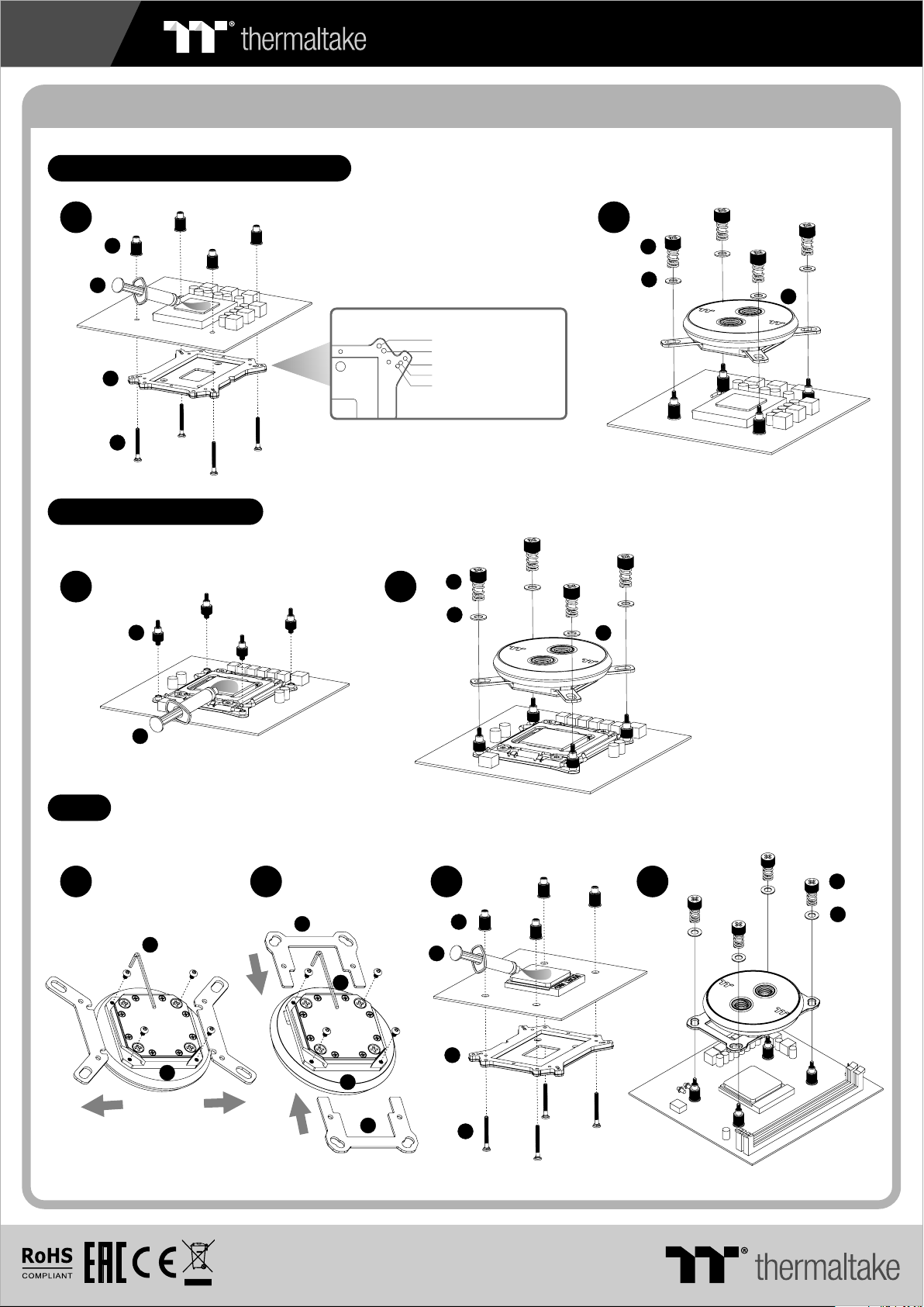
CPU Water Block Installation Guide
Intel LGA 775,LGA115x,LGA1366
C240 DDC SOFT TUBE LIQUID COOLING KIT
1
06
10
03
04
Intel LGA 2011,2011-3
1
08
1.FM2 /FM 1/A M3/ AM2
2.AM4
3.LGA 136 6
4.LGA 1150/ 1151 /115 5/11 56
5.LGA 775
2
05
07
2
05
07
01
01
10
AMD
1 3
09
01
2
02
09
01
02
4
06
10
03
04
05
07
© 2019 Thermaltak e Technology Co., Ltd. All Rights Reserved .
www.thermaltake.com
Page 2
2
C240 DDC SOFT TUBE LIQUID COOLING KIT
Installation Guide
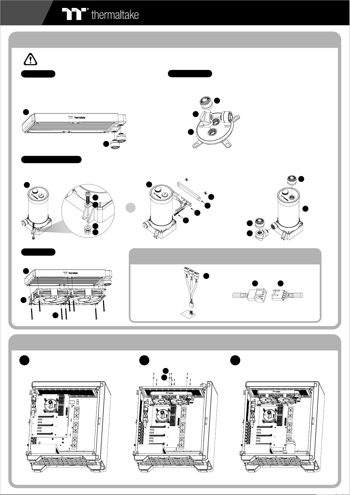
CAUTIONS:
Make sure there is enough space when you start to set up the LCS product
Radiator
To ensure a clean lo op, flush and rinse your radiato rs
and wa ter blocks with distilled water before using.
Make s ure the fittings are screwed securely when
plac ing them onto t he radiator.
21
27
Water Block
Attach the fittings to the inlet and o utlet o f the wat er block.
Pump / Reservoir
Choose the proper way to moun t the pum p and res ervoir by referring to the manual
(suggest vertical placement)
12
15
16
16
14
or
12
27
26
01
Attach fittings onto the pump and re servo ir
27
14
18
13
15
27
26
12
Case Fan
Attach the fans to the radiator
21
20
24
Connect the fan power cable when the liquid cooling system
is completely finished
Connect the PWM
cable to motherboard.
Installation Walkthrough (Example: A500 TG)
Place the motherboard into the cas e. Position the radiator.
1
2
23
22
31
Connect the fan power cable to PWM cab le
2031
Attach the pump and reservoir into
3
the chosen locations.
Page 3

3
C240 DDC SOFT TUBE LIQUID COOLING KIT
Cutting and Attaching the Tubing
Take out th e cap fro m th e fit ti ngs and p lace
1
the cap o f the com pr ess io n fitti ng over t he
tubin g. Push t he e nd of t he t ubing o ver the
barb; m ake sur e th e tub in g is a tigh t fit.
Slide t he cap ov er t he fi tt ing and r otate i t
clock wise un ti l the t ub ing is se aled in p lace.
Measu re the tu be l eng th b ased on t he
4
fitti ng, and m ak e (cu t) t he tube s.
The loo p order : R ad iat or > R eserv oir inl et
Measu re the tu be l eng th b ased on t he fitt ing,
2
and mak e (cut) t he t ube s. The lo op orde r :
Pump Ou tlet > Water B lock
Measu re the tu be l eng th b ased on t fitti ng,
3
and mak e (cut) t he t ube s. The lo op orde r :
Wat er Bloc k > Radia tor
Filling the System
CAUTIONS:
1. Before filli ng t he system, plea se m ake
sure that each fi tt ing as well as unus ed
ports are compl et ely sealed.
2. If there is any ca se o f leaking,
immediately t ur n off the power and
clean the leak
3. If there is any re la ted electroni c pa rts
stained on liqu id c oolant, make su re t o
completely cl ea n and dry the
components. And then m ak e sure they
all work well.
Thermaltake recommends the following steps to be taken after completing your water loop setup
1. It is strongly recommended to use market proven pre-mix co ol an t, s uc h as Thermaltake Coolant 1000. It off er s gr ea t pe rformance
while preventing the entire cooling system – copper, brass, ni ck el , al um in um , an d st ee l – from corrosion.
2. Fill the reservoir with coolant and cycle the power on and off several times while the pump pushing the coolant into the loop.
3. DO NOT let the pump run dry, when there is no liquid entering the pump turn off yo ur p ow er i mm ed ia tely
4. Fill the reservoir to the top as it will prevent air from going in to t he p um p
5. If necessary tilt the system slightly from side to side to b le ed t he a ir o ut o f th e lo op .
6. Place some paper towels under fittings and joining points to t es t fo r le ak s.
7. Run the loop with the fill port open for about 24 hours to completel y bl ee d th e ai r ou t of t he l oo p.
After s witch in g off t he powe r suppl y,
1
conne ct the PS U po wer c or d and
produ ct cabl es .
34
Use the r efill b ot tle t o fi ll cool ant int o the res ervoi r
2
35
Place y our PSU o ut sid e of t he case a nd atta ch it to
3
the pum ps 4pin m ol ex co nn ector, t urn on th e power
of PSU an d make th e re st of t he s yst em f ills up .
Page 4

+5V D G
JRAINBOW
G
4
C240 DDC SOFT TUBE LIQUID COOLING KIT
Motherboard SYNC installation Guide
Connect the Mot he rboard Signal B ri dg e Cable to fan le d ca bl e
CAU TIO NCAU TIO N
Please power off the PC and check
the Positive and Negative ends on
the connector before connecting
the cable to motherboard. Connecting
the wrong end can damage the LEDs.
ASUS ASROCK
Aura Addressable Strip Header(s) Addressable RGB LED Header(s)
29 29 29 30
JRGB-strip He ad er(S)
MSIMSI
11
01
30
29
20
GIGABYTE
AORUS RGB Fusion with Digital LEDs
1
01
Connect the ARGB con tr ol ler to the SATA co nnector.
2
ARGB Controller Installation Guide
Connect the ARGB con tr ol ler to the Fans .
11
32
1. Light Mode:
32
20
Switch over between 7 LED modes.
Wave → Full light → RGB Spectrum → Off → Flow → Ripple → Pulse → Blink
2. Color Mode:
When light mode is in Full Lighted, Pulse and Blink :
Switch over 8 LED colors .
Red → Yellow → Green → Teal → Blue → White → Purple → Rainbow
When light mode is in Ripple :
Switch over 7 LED colors .
Red → Yellow → Green → Teal → Blue → White → Purple
When light mode is in RGB Spectrum:
Click to memorize and lock the color you want, click again to unlock the 256
colors auto rotation.
When light mode is in Wave and Flow :
LED color can not be adjusted.
3. Light Speed:
Switch over between 4 light modes.
Slow → Normal → Fast → Extreme
 Loading...