

Page 1
Core V71
Your Build. Our Core
User's Manual
Benutzerhandbuch
Mode d’emploi
Manual del usuario
Manuale dell’utente
Manual do Utilizador
安裝說明書
用戶手冊
ユーザーズマニュ アル
Руководс тво пользователя
kullanıcı elkitabı
(EEE Yönetmeliğine Uygundur)
คู่มือการใช้
© 2 015 T herma ltake Technol ogy C o., L td. Al l Rig hts R eserv ed. B- 2015. 01
All other r egiste red tra demarks belon g to t heir res pectiv e compa nies.
Tested To C omply
With F CC Standa rds
FOR H OME OR O FFICE USE
www. therm altak e.com
ww w.t he rm al ta ke .c om
Page 2
Join Tt Community To Rece ive Bene fit s
Dear Valued Customer,
Thank you for choosing Thermaltake.
As a new user we value your thoughts and opinions and
your feedback is important to us. We at Thermaltake
would like to use this opportunity to invite you to join our
Community Forums. Register today to start enjoying the
full benefits of our community.
Benefits of being a member:
Quick and responsive user support
Receive help and advice with new builds
Keep up to date with new product releases
Share your thoughts and builds with the community
Enter monthly contests and giveaways
Tt LCS-Liquid Cooling Support Ce rti fication
Tt LCS Certified is a Thermaltake exclusive certification
applied to only products that pass the design and
hardcore enthusiasts standards that a true LCS chassis
should be held to. The Tt LCS certification was created
so that we at Thermaltake can designate to all power
users which chassis have been tested to be best
compatible with extreme liquid cooling configurations to
ensure you get the best performance from the best
features and fitment.
Bra nd off icia l webs ite
htt p:// www.t herm alta ke.c om/
Glo bal Fa cebo ok
htt ps:/ /www. face book .com /The rmaltakeInc
Taiwa n Facebook
htt p:// www.f aceb ook. com/ ThermaltakeTW
Glo bal co mmun ity fo rums
htt p:// comm unity.thermaltake .com
Page 3
Content s
Chapter 1. Product Introduction
1.0
Sp ecifica ti on
1.1
Ac cessory
1.2
War ni ng an d N otice
Chapter 2. Installation Guide
Si de Panel s Dis as sembl y
2.0
Power Supp ly Un it (P SU) I nstal la tion
2.1
Mo therboa rd In stall at ion
2.2
5. 25" D evice Inst al latio n
2.3
3. 5" & 2 .5 " H DD In st allat io n
2.4
HD D C ag e I nstalla ti on
2.5
HD D S up porti ng Br acket In st allti on
2.6
PC I C ar d I ns talla ti on
2.7
Keybo ar d & Mo us e S ec urity Lo ck Us ag e
2.8
Fan Spee d & Ligh t Con tr ol Opera ti on
2.9
Ai r C oo ling Insta ll ation
2.10
Li quid Cooli ng In st allat io n
2.11
Fi lter Insta ll ation
2.12
Chapter3 Leads Installation Guide
Ca se LE D c onnecti on
3.0
US B 2 .0 co nnectio n
3.1
US B 3 .0 co nnectio n
3.2
Au dio c onnec ti on
3.3
01
01
02
04
05
06
08
09
11
11
12
13
14
16
18
20
21
21
21
21
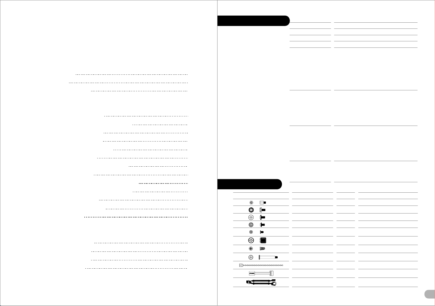
Specification
Accessory
Fig ure
Cas e Type
Dim ensio n (H*W* D) 583 x 2 30 x 560 mm ( 23 x 9.1 x 22 i nch)
Sid e Panel
Mat erial
Coo ling Sy stem
Fan S uppor t
Rad iator S uppor t
Cle aranc e
Par ts Na me
Stand-off#6-32 x 6mm
Screw#6-32 x 6mm
Screw#6-32 x 5mm
Screw M3 x 5mm
Screw M3 x 5mm
Nut Setter
Screw Ø5 x 12mm
Screw#6-32 x 32mm
Cable Tie
Buzzer
8-pin Extension Cable
Ful l Towe r
Tran spare nt Wind ow
SPC C
Fro nt (int ake) :
200 x 2 00 x 30 mm Bl ue LED fa n x 2
(60 0~800 rpm, 13 ~15dB A)
Rea r (exha ust) :
140 x 1 40 x 25 mm Tur bo fan x 1
(10 00rpm , 16dBA )
Top (e xhau st) :
200 x 2 00 x 30 mm Bl ue LED fa n x 1
(60 0~800 rpm, 13 ~15dB A)
Fro nt :
3 x 120 mm, 2 x 140 mm, 2 x 200 mm
Top :
3 x 120 mm, 2 x 140 mm, 2 x 200 mm
Rea r :
1 x 120 mm, 1 x 140 mm
Bot tom :
2 x 120 mm
Fro nt :
1 x 360 mm, 1 x 420 mm
Top :
1 x 360 mm, 1 x 420 mm
Rea r :
1 x 120 mm
Bot tom :
1 x 240 mm
CPU c ooler h eight l imita tion: 1 85mm
VGA le ngth li mitat ion: 31 0mm(w ith HDD r ack)
480 mm(wi thout H DD rack )
PSU l ength l imita tion: 2 20mm (W ith Bot tom Fan )
Q't y
4
4
10
20
32
1
4
4
5
1
1
Use d for
Motherboard
Power
HDD
Motherboard , ODD
2.5" HDD
Stand-off
Case Fan
200mm x 30mm Fan
Cable Management
Motherboard Alarm
Power Connector Extension Cable
1
Page 4
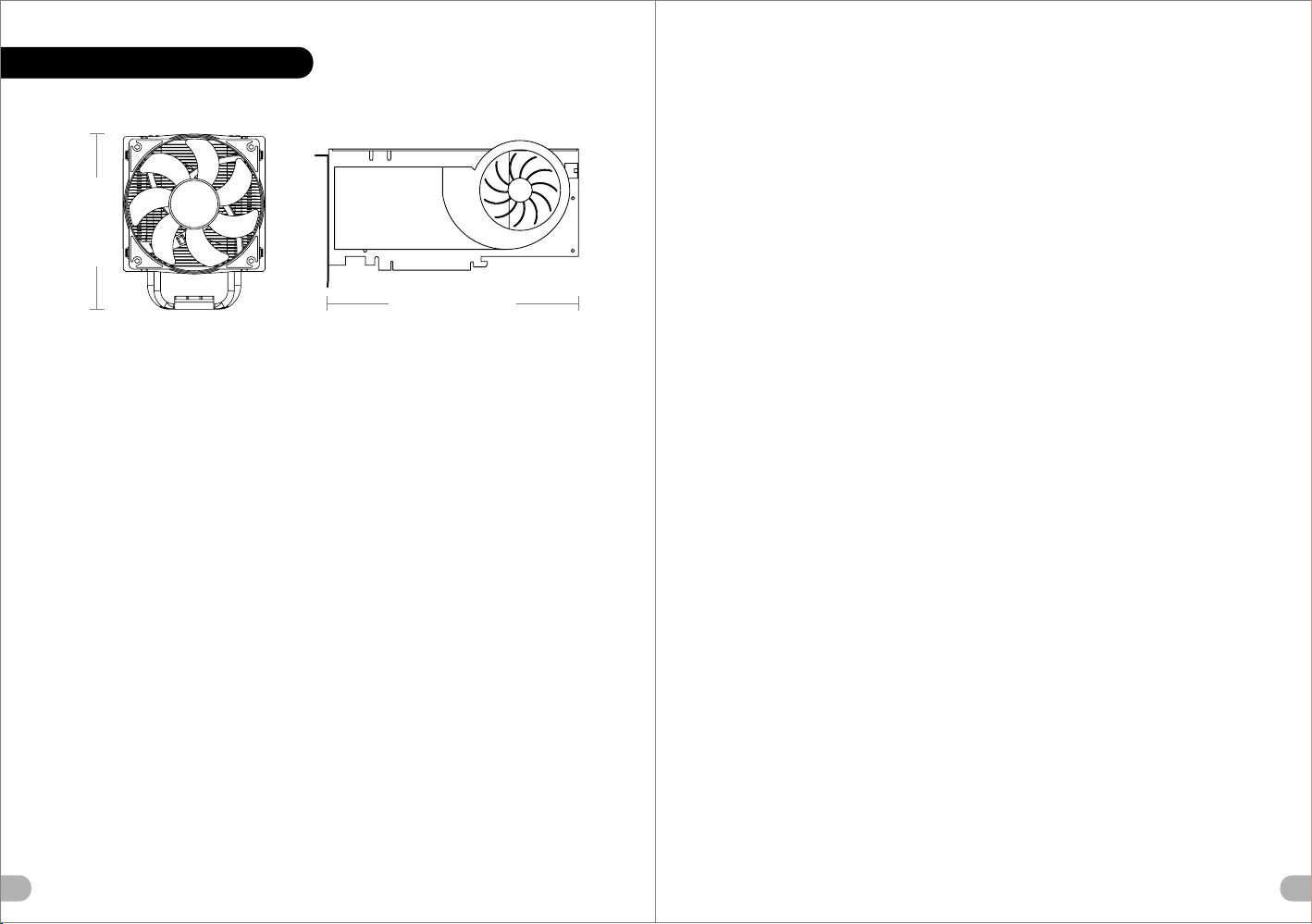
Warn ing and Notice
Atençã o!!
Limite de altura para o dissipador do CPU:
O limite de altura para o dissipador do CPU é 185 mm (7,3 polegadas).
Limite de comprimento para VGA (placa gráfica):
O limite de comprimento para VGA (placa gráfica) é 310 mm (12.2 polegadas).
<1 85 mm
<3 10 mm
War ning!!
CPU Cooler Height Limitation:
Please ensure that your CPU cooler does NOT exceed 185mm (7.3 inches) height.
VGA (Add-on card) Length Limitation:
Please ensure that your VGA (Add-on card) does NOT exceed 310mm (12.2 inches) length.
Warnun g!!
CPU-Kühler Höhenbeschränkung:
Bitte stellen Sie sicher, dass Ihr CPU-Kühler 185 mm (7,3 Zoll) Höhe nicht überschreitet.
VGA (Add-on-Karte) Längenbeschränkung:
Bitte stellen Sie sicher, dass Ihre VGA (Add-on-Karte) 310 mm (12,2 Zoll) Länge nicht
überschreitet.
Averti ssement !
Limite de hauteur du ventilateur de CPU :
Vérifiez que la hauteur du ventilateur de CPU ne dépasse pas 185 mm.
Limite de longueur de la carte (complémentaire) VGA :
Vérifiez que la longueur de votre carte (complémentaire) VGA ne dépasse pas 310 mm
Precaución
Limitación de altura del refrigerador de CPU:
Asegúrese de que la altura de su refrigerador de CPU no excede los 185 mm (7,3 pulgadas).
Limitación de longitud de la tarjeta de vídeo (adicional):
Asegúrese de que la longitud de su tarjeta de vídeo (adicional) no excede los 310 mm (12,2
pulgadas).
Attenzione!
Limitazione altezza dissipatore CPU:
Assicurarsi che l’altezza del dissipatore CPU NON superi 185 mm (7,3 pollici).
Limitazione lunghezza VGA (scheda aggiuntiva):
Assicurarsi che la lunghezza del VGA (scheda aggiuntiva) NON superi 310 mm (12,2 pollici).
警告!!
CPU 冷卻器的 高度限 制:
請確保 CPU 冷卻 器的高 度不超過 185 mm (7.3 英 吋)。
VGA (附加介面 卡) 的長度 限制:
請確保 VGA (附加 介面卡) 的 長度不超過 310 mm (12.2 英吋)。
警告!!
CPU 散热器高 度限制 :
请确保 CPU 散热 器的高 度不超过 185 mm(7.3 英寸 )。
VGA(附加卡 )长度 限制:
请确保 VGA(附 加卡) 的长度不超过 310 mm(12 .2 英寸 )。
警告
CPUクーラー の高さ 制限:
CPUクーラー の高さ が185mmを超えていな いこと を確認してください。
VGA(アドオ ンカー ド)の長さ制限:
VGA(アドオ ンカー ド)の長さが310mmを 超えて いないことを確認して くださ い。
Внимание!
Ограничение по высоте охладителя ЦП
Убедитесь, что высота охладителя ЦП (центрального процессора) НЕ превышает 185 м
(7,3 дюйма).
Ограни чен ие по длине виде ока рты VGA (плата ра сши рения)
Убедит есь, ч то длина видео кар ты VGA (плата рас шир ения) НЕ превыш ает 3 10 мм
(12,2 дю йма) .
Uyarı!!
CPU Soğutucu Yükseklik Sınırlaması:
Lütfen CPU soğutucunuzun yüksekliğinin 185mm’yi (7,3 inç) GEÇMEDİĞİNDEN emin olun.
VGA (Eklenti kartı) Uzunluk Sınırlaması:
Lütfen VGA’nızın (Eklenti kartı) uzunluğunun 310mm’yi (12,2 inç) GEÇMEDİĞİNDEN emin
olun.
คำเตือน!!
ขีดจำกัดความสูงสำหรับฮีตซิงก์ของ CPU:
ขีดจำกัดความสูงสำหรับฮีตซิงก์ของ CPU คือ 185 มม. (7.3 นิ้ว)
ขีดจำกัดความยาวสำหรับ VGA (การ์ดแสดงผล):
ขีดจำกัดความยาวสำหรับ VGA (การ์ดแสดงผล) คือ 310 มม. (12.2 นิ้ว)
2
3
Page 5
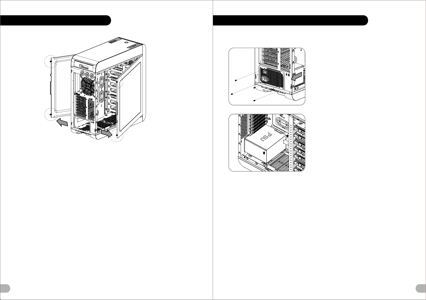
Side Panel s Dis ass embly
English /
Remove the screws on the back of the chassis,
and open the side panel
Deutsch /
Entfernen Sie die Schrauben auf der Rückseite
des Gehäuses und öffnen Sie das Seitenteil
Français /
Enlevez les vis à l’arrière du châssis et ouvrez le
panneau latéral
Español /
Extraiga los tornillos de la parte posterior de la
caja y abra el panel lateral
Italiano /
Rimuovere le viti sulla parte posteriore dello
chassis e aprire il pannello laterale
Português/
Remova os parafusos na parte de trás da caixa e
abra o painel lateral
繁體中文 /
移除機殼後 方螺絲,將側窗打開
简体中文 /
卸除机壳后 方螺丝,将侧窗打开
日本語 /
シャーシ背 面のねじを取り外し、サイドパネ
ルを開きま す
Русск ий /
Откру тите винты на задней стенке корпуса
и откройте боковую панель
Türkçe /
Kasanın arkasındaki vidaları çıkarın ve yan
paneli açın
ภาษาไทย /
ถอดสกรูที่ด้านหลังของแชสซีส์
แล้วเปิดแผงด้านข้าง
Power Supp ly Un it (PSU) Installation
Español /
1. Instale la PSU en la ubicación correcta.
2. Ajuste el puente de soporte de la PSU en la
ubicación adecuada y asegúrela con tornillos.
Italiano /
1. Posizionare la PSU in modo corretto.
2. Regolare il ponticello di supporto della PSU nella
posizione corretta e fissare la PSU con delle viti.
Português/
1. Coloque o PSU na sua devida posição.
2. Ajuste a ponte de suporte do PSU para a devida
posição e fixe o PSU com parafusos.
繁體中文 /
1. 將電源供應器放在正確的位置
2. 將電源供應器支撐架調整到適當的位置,然後用螺絲
固定電源供應器。
简体中文 /
1. 将电 源供应器放在正确的位置
2. 将电源供应器支撑架调整到适当的位置,然后用螺丝
固定电源供应器。
日本語 /
1. PSUを適切なロケーションに取り付けます。
2. PSU支持ブリッジを適切なロケーションに合うよう
English /
1. Place the PSU in proper location.
2. Adjust the PSU supporting bridge to the proper
location and secure the PSU with screws.
Deutsch /
1. Platzieren Sie das Netzteil in der richtigen
Position.
2. Richten Sie die Stützbrücke für das Netzteil
entsprechend aus und sichern Sie das Netzteil
mit Schrauben.
Français /
1. Placez l’alimentation dans la position appropriée.
2. Ajustez le pont de support de l’alimentation dans
la position appropriée et fixez l’alimentation à
l’aide des vis.
に調整し、 ねじでPSUを締め付けます。
Русский /
1. Ус тановите блок питания в надлежащее место.
2. Надлежащим образом установите
поддерживающий мост блока питания и закреп
ите блок питания винтами.
Türkçe /
1. PSU’yu, uygun konuma yerleştirin.
2. PSU destek köprüsünü uygun konuma ayarlayın ve
PSU’yu vidalarla sabitleyin.
ภาษาไทย /
1. วาง PSU ในตำแหน่งที่เหมาะสม
2. ขยับบริดจ์ที่รองรับ PSU ให้อยู่ในตำแหน่งที่เหมาะสม
แล้วขันสกรูยึด PSU ให้แน่น
4
5
Page 6

Motherboard Insta lla tio n
English /
1.Lay down the chassis.
2.Install the motherboard in proper location and
secure it with screws.
Deutsch /
1.Legen Sie das Gehäuse auf die Seite.
2.Installieren Sie die Hauptplatine in ihrer
vorgesehenen Position und sichern Sie sie mit
Schrauben.
Français /
1.Posez à plat le châssis.
2.Installez la carte mère dans l'endroit approprié et
sécurisez-la avec des vis.
Español /
1. Tumbe el chasis.
2. Instale la placa madre en la ubicación adecuada
y asegúrela con tornillos.
Italiano /
1.Poggiare lo chassis.
2.Installare la scheda madre nella posizione
appropriata e fissarla con le viti.
Português/
1. Deixe a caixa.
2. Instale a motherboard no local adequado e
aparafuse.
繁體中文 /
1. 將機殼平放。
2. 將主機板放置在合適的位置並用零件包中之螺
絲固定。
简体中文 /
1. 放平机箱。
2. 在合适的位置安装主板并以螺丝安全固定。
日本語 /
1.シャーシ を下に置きます。
2.マザーボ ードを適切な場所に取り付け、ねじで
固定します 。
Русский /
1. Раск ройте системный б лок.
2. Уста новите материнс кую плату в
надле жащее место и закре пите ее вин тами.
Türkçe /
1.Kasayı yan yatırın.
2.Ana kartı uygun konuma takın ve vidalarla
sabitleyin.
ภาษาไทย /
1.วางแชสซีส์นอนลง
2.ติดตั้งเมนบอร์ดในตำแหน่งที่เหมาะสม
แล้วขันสกรูยึดให้แน่น
5.25" Device Installat ion
Type A
Type B
English /
1. Pull out the front panel.
2. Remove the 5.25” drive bay cover.
3. Insert the 5.25” device and tighten it with the screws.
4. Slide the 5.25” device into the drive bay to lock the
device.
Note: Press the 5.25” tool-free mechanism to unlock the
device.
Deutsch /
1. Ziehen Sie das Frontpanel heraus.
2. Entfernen Sie die Abdeckung des 5,25 Zoll
Laufwerksschachts.
3. Ön panelin arkasındaki dört kanca kelepçesini itip
serbest bıraktıktan sonra ön paneli sökün.
4. Schieben Sie the 5,25 Zoll Einheit in den
Laufwerksschacht, um die Einheit zu sperren.
Anmerkung: Drücken Sie den 5,25 Zoll werkzeuglosen
Mechanismus, um die Einheit zu verriegeln.
Français /
1. Tirez le panneau de devant.
2. Enlevez le couvercle de la baie de lecteur de 5,25".
3. Insérez le périphérique 5,25 pouces puis fixez-le à
l’aide des vis.
4. Faites glisser le périphérique de 5,25" dans la baie de
lecteur.
Remarque : Appuyez sur le mécanisme sans outil de
5,25" pour déverrouiller le périphérique.
Español /
1. Tire del panel frontal.
2. Extraiga la tapa del hueco de la unidad de 5,25".
3. Inserte el dispositivo de 5,25” y apriételo con los
tornillos.
4. Meta el dispositivo de 5,25” en el hueco de la unidad
para cerrar el dispositivo.
Nota: Presione el mecanismo libre de herramienta de
5,25” para abrir el dispositivo.
Italiano /
1. Tirare verso l' esterno il pannello anteriore
2. Rimuovere il coperchio dell’alloggiamento vano unità
da 5,25’’.
3. Inserire il dispositivo da 5,25” e fissarlo con le viti.
4. Fare scorrere il dispositivo da 5,25” nell’alloggiamento
dell’unità per bloccare il dispositivo.
Nota: Premere il meccanismo tool-free da 5,25” per
sbloccare il dispositivo.
6
7
Page 7

3.5" & 2.5" HDD Installati on
Português/
1. Puxe o painel dianteiro para fora.
2. Remova a cobertura da baía da unidade de 5,25".
3. Insira o dispositivo de 5,25" e aparafuse.
4. Deslize o dispositivo de 5,25" para a baía da
unidade, para bloquear o dispositivo.
Nota: Pressione o mecanismo de 5,25" sem utilizar
ferramentas para desbloquear o dispositivo.
繁體中文 /
1. 拉面板底部,將面板從機殼本體拆下。
2. 移除5.25”擴充槽檔板
3. 插入5.2 5”裝置並用螺絲鎖上。
4. 將5.25”裝置至適當的位置
注意: 如需移除5.25”裝置,先按壓5.25”無螺機機構,
再將5.25”裝置往前推出。
简体中文 /
1. 拉出前面 板。
2. 移除5.25”槽盖
3. 插入5.2 5”装置并用螺丝锁上。
4. 将5.25”设备滑入驱动器槽
注意: 如需移除5.25”设备,先按压5.25”免用工具机械
装置,再将5.25”设备往前推出
日本語 /
1. 前面パネ ルを引き出しま す。
2. 5.25”ドライブベイのカバーを取り外します。
3. 5.25” デバイスを挿入し、ねじで締め付けます。
4. 5.25”デバイスをドライブベイにスライドさせてデ
バイスをロックします。
注: 5.25”工具不要メカニズムを押してデバイスをア
ンロックします。
Русский /
1. Сним ите перед нюю панел ь.
2. Сним ите крышку отсека для 5,25-дюймовых
диско водов.
3. Уста новите 5,25-дюймовое устройство и заф
иксир уйте его винтами.
4. Вставьте 5,25-дюймовое устройство в отсек
диско вода для фиксации.
Примечание. Нажмите на не требующий
использования инструментов механизм отсека
для 5,25-дюймовых дисководов, чтобы
разблокировать устройство.
Türkçe /
1. Ön pan eli çekerek çıkarın.
2. 5,25" sürücü bölmesi kapağını çıkarın.
3. 5.25” aygıtını yerleştirin ve vidalarla sabitleyin.
4. 5,25” aygıtını kilitlemek için sürücü bölmesinin
içine doğru kaydırın.
Not: Aygıtın kilidini açmak için 5,25” araçsız
mekanizmayı bastırın.
ภาษาไทย /
1. ถอดแผงด้านหน้าออก
2. ถอดฝาปิดช่องไดรฟ์ขนาด 5.25" ออก
3. ใส่อุปกรณ์ขนาด 5.25” เข้าไปแล้วขันสกรูยึดให้แน่น
4. เลื่อนอุปกรณ์ขนาด 5.25"
เข้าในช่องไดร์ฟเพื่อล็อคอุปกรณ์
หมายเหตุ: กดตัวล็อคเครื่องมือขนาด 5.25"
เพื่อปลดล็อคอุปกรณ์
Type A
Lockin g cli ps
For 3 .5" HDD: Secure 3.5" HDD fr om both side of
the H DD tray by locking clips.
Remove t his l ock ing c lip
For 2 .5" HDD: Secure 2.5" HDD
fro m the bottom of the HDD by
scr ews.
Type B
8
9
Page 8

HDD Cage Installation
English /
1.Press a latch to pull the tray out.
2. Remove the locking clips then posit ion the HDD
in the tray and secure the HDD with the lock ing
clips.
3. Slide the tray back to the drive bay.
Deutsch /
1. Drücken Sie auf eine Lasche, um den Sch acht
herauszuziehen.
2. Entfernen Sie die Halte-Clips, po sitionieren Sie
dann die HDD in dem Schacht und befestig en Sie
die HDD mit den Halte-Clips.
3. Schieben Sie den Schacht zurück in de n
Laufwerksschacht.
Français /
1. Appuyez sur un loquet pour enlever le b oîtier.
2. Enlevez les clips de verrouillage p uis placez le
disque dur dans le boîtier et fixez le dis que dur
avec les clips de verrouillage.
3. Refaites glisser le boîtier dans la b aie de lecteur.
Español /
1. Presione un pasador para extraer la b andeja.
2. Extraiga los ganchos de bloqueo, co loque el
disco duro en la bandeja y fíjelo con los ga nchos
de bloqueo.
3. Vuelva a meter la bandeja en el hueco de la
unidad.
Italiano /
1. Stringere un laccio per estrarre il v ano.
2. Rimuovere le clip di bloccaggio, qu indi
posizionare l’HDD nel vano e fissarl o con le clip
di bloccaggio.
3. Fare scorrere il vano verso l’allog giamento
dell’unità.
Português/
1. Prima um trinco para puxar a bandeja pa ra fora.
2. Remova os clipes de bloqueio e posici one o
disco rígido na bandeja. Prenda o disc o rígido
com os clipes de bloqueio.
3. Deslize a bandeja de volta para a baía da
unidade.
繁體中文 /
1. 輕壓硬碟托盤左側開啟硬碟托盤,並向外拉出
硬碟托盤。
2. 先移除左右2片扣具,將硬碟放至於硬碟托盤
上,扣具扣回固定硬碟。
3. 將硬碟托盤放回硬碟磁架中,按壓硬碟托盤把
手以固定硬碟。
简体中文 /
1. 压下免用工 具机械装置以卸下硬盘 托盘, 然后
拉出托盘。
2. 卸下2个扣具, 将硬盘驱动器放置在托 盘上, 然
后压回扣具固 定。
3. 将硬盘托盘 滑回硬盘盒,并按下把 手以锁 定硬
盘托盘。
日本語 /
1. ラッチを押 してトレイを引き出し ます。
2. ロッキング クリップを取り外して からHDDを
トレイに設置 し、HDDをロッキングク リップ
で固定します 。
3. トレイをド ライブベイまでスライ ドさせ て戻
します。
Русский /
1. Нажми те защелку, что бы вы тянуть ло ток.
2. Сними те фиксаторы, в ста вьте жест кий
диск в лот ок и закрепите д иск ф иксатор ами.
3. Устан овите лоток об рат но в отсек
дисков ода.
Türkçe /
1. Tepsiyi dışarı çekmek i çin b ir mandal a bas ın.
2. Kilit leme klipsin i çık arın ve HDD ’yi t epsinin
içine ye rleştirip ki lit leme klip siy le sabitleyi n.
3. Tepsi yi tekrar sürü cü bö lmesini n içi ne
kaydır ın.
ภาษาไทย /
1. กดสลักเพื่อดึงถาดออก
2. ถอดคลิปล็อคออก จากนั้นวางฮาร์ดดิสก์ไดรฟ์
ลงในถาดแล้วล็อคไว้ด้วยคลิปล็อค
3. เลื่อนถาดกลับเข้าไปในช่องไดร์ฟ
Type A
Type B
Type C
1
2
3
4
5
6
7
8
HDD Supporting Bracke t Installtion
Type A
Type B
10
11
Page 9

PCI Card Installati on
Keyboard & Mouse Securi ty Lock Us age
English /
Insert the PCI card into the PCI slot, and
secure it with screw.
Deutsch /
Stecken Sie die PCI Karte in den PCI
Steckplatz und sichern Sie sie mit
Schrauben.
Français /
Insérez la carte PCI dans le slot PCI et
sécurisez-la avec des vis.
Español /
Inserte la tarjeta PCI en la ranura del PCI
y asegúrela con tornillos.
Italiano /
Inserire la scheda PCI nello slot PCI e
fissarla con la vite.
Português/
Insira a placa PCI na ranhura PCI e fixe
com parafusos.
12
繁體中文 /
將 PCI 卡插入 PCI 插槽,然後用螺絲固定。
简体中文 /
将 PCI 卡插入 PCI 插槽并以螺丝固定。
日本語 /
PCI カードを PCI スロットに挿入し、ねじで
固定します。
Русский /
Вставьте PCI-карту в слот PCI и закреп
ите ее винтом.
Türkçe /
PCI kartını, PCI yuvasına yerleştirin ve
vidayla sabitleyin.
ภาษาไทย /
ใส่การ์ด PCI ในสล็อต PCI
แล้วขันสกรูยึดให้แน่น
English /
Place the keyboard or mouse cables through the
“Keyboard & Mouse Security Lock” then secure it
back to the back panel from inside of the chassis
with screw.
Deutsch /
Führen Sie die Kabel durch die Einheit “Tastatur- &
Maussperren” und sichern Sie sie dann wieder an
der Rückwand innerhalb des Gehäuses mit den
Schrauben.
Français /
Mettez les câbles du clavier ou de la souris à travers
le “verrou de sécurité de clavier & souris” puis
sécurisez-les sur le panneau arrière à l'intérieur du
châssis avec des vis.
Español /
Mettez les câbles du clavier ou de la souris à travers
le “verrou de sécurité de clavier & souris” puis
sécurisez-les sur le panneau arrière à l'intérieur du
châssis avec des vis.
Italiano /
Posizionare i cavi della tastiera o del mouse sulla
“tastiera e il blocco di sicurezza del mouse”, quindi
fissarli sul pannello posteriore dall’interno dello
chassis con la relativa vite.
Português/
Passe os cabos do teclado ou do rato através do
"Bloqueio de Segurança do Teclado e Rato" e fixe
na parte traseira do painel no interior do chassis,
com parafusos.
繁體中文 /
將鍵盤或滑鼠纜線穿過「鍵盤和滑鼠安全鎖」,然後用
螺絲將其固定回機殼內的背板。
简体中文 /
将键盘或鼠标缆线穿过“键盘和鼠标安全锁”,然后用螺
丝将其固定回机箱内侧。
日本語 /
「キーボードとマウスのセキュリティロック」を通し
てキーボードまたはマウスケーブルを収納し、ねじで
シャーシ内部から背面パネルに再び締め付けます。
Русский /
Проведите кабели клавиатуры и мыши через зам
ок и подключите их. Закрутите замок обратно изн
утри корпуса.
Türkçe /
Klavye veya fare kablolarını “Klavye ve Fare
Güvenlik Kilidi” üzerinden yerleştirin ve daha sonra,
güvenlik kilidini kasanın iç tarafından arka panele
yeniden vidalayın.
ภาษาไทย /
เดินสายแป้นพิมพ์หรือสายเมาส์ลอดผ่าน
“อุปกรณ์เก็บสายแป้นพิมพ์และเมาส์”
จากนั้นให้ขันสกรูยึดอุปกรณ์เก็บสายพร้อมสายเข้ากับ
แผงด้านหลังของแชสซีส์ให้แน่น
13
Page 10

Fan Sp eed & L ight Control Operat ion
English /
1. LED Light Control – Press to switch LEDs color
(ON/OFF)
2. Fan Speed Control – Press to switch the fan
speed.
Deutsch /
1. LED Helligkeitssteuerung – Drücken Sie diesen
Schalter, um die LED-Farben zu wechseln
(ON/OFF)
2. Lüftersteuerung – Drücken Sie hier, um die
Lüftergeschwindigkeit einzustellen.
Français /
1. Commande de voyant : appuyez pour changer la
couleur des voyants (ON/OFF)
2. Contrôle de vitesse de ventilateur : appuyez
pour modifier la vitesse du ventilateur.
Español /
1. Control de indicadores LED: pulse para cambiar
el color de los LED (ON/OFF)
2. Control de velocidad del ventilador: pulse para
cambiar la velocidad del ventilador.
Italiano /
1. Controllo luce LED – Premere per
attivare/disattivare il colore dei LED (ON/OFF)
2. Controllo velocità ventola – Premere per
attivare/disattivare la velocità della ventola.
Português/
1. Luz LED de controlo - Prima para alterar a cor
dos LEDs (ON/OFF)
2. Controlo de velocidade da ventoinha - Prima para
alterar a velocidade da ventoinha.
14
繁體中文 /
1. LED 燈控制 – 按按鈕以切換 LED 燈的顏色
(開/關)
2. 風扇轉速控制 – 按按鈕以切換風扇轉速。
简体中文 /
1. LED 灯控制 – 按按钮以切换 LED 灯的颜色
(开/关)
2. 风扇转速控制 – 按按钮以切换风扇转速。
日本語 /
1. LEDライトコントロール – このスイッチを押して
LEDを切り替えます。(ON/OFF)
2. ファ ン速度制御 – このボタンを押してファン速度
を切り替え ます。
Русский /
1. Пе реключатель светодиодной подсветки — н
ажмите, чтобы изменить цвет индикатора
(ON/OFF)
2. Регулятор скорости вентилятора — нажмите
для изменения скорости вращения.
Türkçe /
1. Işık Denetimi – Işıkların rengini değiştirmek
için düğmeye basın (ON/OFF)
2. Fan Hızı Denetimi – Fan hızını değiştirmek için
basın.
ภาษาไทย /
1. การควบคุมไฟ LED – กดเพื่อสลับสีของไฟ LED
(ON/OFF)
2. การควบคุมความเร็วของพัดลม –
กดเพื่อสลับเปลี่ยนความเร็วของพัดลม
Fan Speed & Light Controller Connector Descriptions
① 4-pin peripheral connector
②,③,④ Fan power & signal connector (Front & Top)
WARNING!
Fan speed and light controller are with
built in 200mm LED fans. To avoid on damaging the
circuit board, please do not connect it with other fans.
風扇&LED控制器僅與內建原廠200mm LED風扇相容, 請
勿連接其他風扇, 以避免電路板損壞。
1
2
3
only compatible
4
15
Page 11

Air Cooling Install ati on
Rear
14cm x 1
Top 20cm Fan
Installation Notice
1. Remo ve the I/ O brack et first
2. Inst all the 2 0cm fan w ith screws
Top
12cm x 3
14cm x 2
20cm x 2
20cm x 2
12cm x 1
16
12cm x 2
Bottom
14cm x 2
Front
12cm x 3
Bottom Fan
Installation Notice
1. Remo ve the bo ttom
fan fil ter fir st
2. Inst all the f an with s crews
17
Page 12

Liquid Cooling Inst all ation
Maximum Radiator Installation Notice
Rear
12cm x 1
12cm x 1
24cm x 1
Top
36cm x 1
42cm x 1
42cm x 1
36cm x 1
Front
20cm Fa n
42cm Ra diato r
36cm Ra diato r
20cm Fa n
Bottom
18 19
Page 13

Filter Installati on
Leads Installatio n
English
Leads Ins tallation Gu ide
Case LED C onn ect ion / On t he fron t of the ca se, you c an find s ome LED s and swi tch lea ds. Ple ase con sult yo ur user
man ual of yo ur moth erboa rd manu factu rer, th en conn ect the se lead s to the pa nel hea der on th e mothe rboar d.
USB 2.0 Co nne cti on / Ple ase con sult yo ur moth erboa rd manu al to fin d out the s ectio n of “USB c onnec tion” .
USB 3.0 co nne cti on /
1. Ma ke sure y our mot herbo ard sup ports U SB 3.0 co nnect ion.
2. Co nnect t he USB 3. 0 cable t o the ava ilabl e USB 3.0 p ort on yo ur comp uter.
Aud io Co nne ction / Please re fer to th e follo wing il lustr ation o f Audio c onnec tor and y our mot herbo ard use r manua l.
Ple ase sel ect the m other board w hich us ed AC’9 7 or HD Aud io(Az alia) ,(be aw are of th at your a udio su pport s AC’97 o r HD
Aud io (Aza lia)) o r it will d amage y our dev ice(s ).
Deutsch
Ansch lüsse h er stellen
Gehäus e-L ED- Verb indu nge n / Auf de r Gehäu sevor derse ite fin den Sie e inige L EDs und V erbin dunge n. Bitt e nehme n
Sie d ie Gebr auchs anwei sung Ih res Mot herbo ard Her stell ers zur H ilfe un d schli eßen Si e diese V erbin dunge n an die Pa nel
Hea der Bel egung d es Moth erboa rds an.
USB 2.0 An sch luss / B itte ne hmen Si e die Geb rauch sanwe isung I hres Mo therb oards z ur Hilf e und les en Sie un ter dem
Kap itel „U SB Ansc hlüss e“ nach .
USB 3.0 An sch luss /
1. St ellen S ie sich er, das s Ihre Ha uptpl atine d en USB 3. 0 Ansch luss un terst ützt.
2. Ve rbind en Sie da s USB 3.0 K abel mi t dem USB 3 .0 Port a uf Ihre m Compu ter.
Aud io An schlüss e / Bitte beachten Sie die folgende Abbil dung de r Audio A nschl üsse un d die Anw eisun g in der
Geb rauch sanwe isung I hres Mo therb oards . Bitte w ählen S ie das Mo therb oard, d as AC’9 7 oder HD A udio( Azali a)
ver wende t, (ach ten Sie d arauf , dass Ih r Audio A C’97 bz w. HD Aud io (Aza lia unt erstü tzt)) . Ander nfall s entst ehen sc hwere
Sch äden an I hrem( n) Gerä t(en) !!!
L- OUT
SE NSE
R-O UT
MI C-P OWE R
MI C-I N
L- OUT
SE NSE 2
KE Y
SE NSE 1
PR ESE NSE
GN D
L- RET
KE Y
R-O UT
R-R ET
MI C-P OWE R
MI C-I N
USB 3.0 Connection
GN D
20 21
Page 14

Français
Guide d'in stallation des fil s
Con nexio n des voyan ts du boîtier / S ur la fa ce avan t du boî tier, vous trouverez plusieurs voyant s et les fils de s
bout ons. S' il vous plaît consultez le guide d'utili sateur du fabricant de votre carte mèr e, puis connect ez ces f ils aux
onne cteurs sur la c arte mère.
Con nexio n USB 2.0 / S'il vous pla ît consultez le manuel de votre carte m ère à la section "Connexion USB"
Con nexio n USB 3.0 /
1. Vé rifie z que vot re cart e mère pr end en ch arge la c onnex ion USB 3 .0.
2. Co nnect ez le câb le USB 3. 0 au port U SB 3.0 di sponi ble sur v otre or dinat eur.
Con nexio n Aud io / S' il vous plaît r éférez vous à l'illustrati on suivante d u connecteur audio et au g uide de l'utilisateu r de
votr e carte mère. S 'il vous plaît sélectionnez une carte mère supportant AC'97 ou HD Au di (Azalia), (faites attention que
votr e audio supporte l'AC'97 ou HD Au dio (Az alia)) sinon cela pourrait endommager votre matériel.
Italiano
Guida di insta llazione dei contatti
Con nessione d el LE D del case / Nella parte a nteriore del case, sono presenti alcuni contatti per interruttori e LED.
Cons ultare il manuale utente del pro duttore della s cheda m adre, quindi connettere i contatti alla parte su periore del
pann ello su lla scheda madre.
Con nessione U SB 2. 0 / Co nsultar e il man uale pe r la sch eda madre che comprende la sezione relative alla
“con nessione USB”.
Con nessione U SB 3. 0 /
1. Ac certa rsi che l a sched a madre s uppor ti la con nessi one USB 3 .0.
2. Co llega re il cav o USB 3.0 a lla por ta USB 3. 0 dispo nibil e sul com puter .
Connes sio ne Audio / Fa re rife rimen to all’ illus trazi one rip ortat a di segu ito del c onnet tore Au dio e al ma nuale u tente p er
la sc heda ma dre.S elezi onare l a sched a madre r elati va a AC’9 7 o HD Audi o (Azal ia) e con sider are che i l suppo rto aud io è
com patib ile con A C’97 o HD A udio (A zalia ); in cas o contr ario, l e perif erich e potre bbero v enire d anneg giate .
Español
Guía de Instal ación de Ca bles
Con exión del L ED de la caja / E n la par te frontal de la caja , encontrará algunos LED y cables de in terrupt ores. C onsulte
el manual del usuario del fabricant e de la placa madre, a con tinuaci ón cone cte estos cables al conector de l a placa madre.
Con exión USB 2 .0 / C onsulte el manu al de la placa m adre pa ra obtener más información sobre el a partado “Conexión USB"
Con exión USB 3 .0 /
1. As egúre se de que l a placa b ase adm ite con exión U SB 3.0.
2. Co necte e l cable U SB 3.0 al p uerto U SB 3.0 di sponi ble en el e quipo .
Con exión de Au dio / Consult e la sig uiente ilustra ción de l conector de Audio y el manual del usuario de la placa m adre.
Sele ccione la placa madre que u tiliza AC’97 o HD Aud io (Azalia), (asegúrese de que su audio admite AC’97 o HD Audio
(Aza lia)) s i no, su s dispositivos resultará n dañad os
L- OUT
SE NSE
R-O UT
MI C-P OWE R
MI C-I N
L- OUT
R-O UT
MI C-P OWE R
MI C-I N
USB 3.0 Connection
SE NSE 2
KE Y
SE NSE 1
PR ESE NSE
GN D
L- RET
KE Y
R-R ET
GN D
Português
Guia de Ins talaç ão Eléc trica
Ligaçã o do LE D da Ca ixa / Na p arte di antei ra da cai xa pode e ncont rar alg uns LED s e fios el éctri cos. Co nsult e o
man ual de ut iliza dor do fa brica nte da su a mothe rboar d e ligue o s fios à pa rte sup erior d o paine l na moth erboa rd.
Ligaçã o UBS 2 .0 / Con sulte o m anual d a sua mot herbo ard par a ver a sec ção de “L igaçã o USB”.
Ligaçã o USB 3 .0 /
1. Ce rtifi que-s e que a sua m other board s uport a ligaç ão USB 3. 0.
2. Li gue o cab o USB 3.0 à p orta US B 3.0 dis ponív el no seu c omput ador.
Ligaçã o Áud io / Con sulte a i magem s eguin te do con ector Á udio e o ma nual de u tiliz ador da s ua moth erboa rd.
Sel eccio ne a moth erboa rd que ut iliza A C’97 ou H D Áudio (Azal ia), (v erifi que se a su a placa d e áudio s uport a AC’97 o u HD
Áud io(Az alia) ) ou irá da nific ar o(s) s eu(s) d ispos itivo (s).
L- OUT
SE NSE
R-O UT
MI C-P OWE R
MI C-I N
L- OUT
R-O UT
MI C-P OWE R
MI C-I N
USB 3.0 Connection
SE NSE 2
KE Y
SE NSE 1
PR ESE NSE
GN D
L- RET
KE Y
R-R ET
GN D
2322
Page 15

繁體中文
線材安裝說明
機殼LE D連接方式
並將機 殼上的線材 正確地連接 到主機板上 ,這些線材 通常都會印 有標籤在上 面,如果沒 有的話,請 找出機殼前 方面板上線 材原
本的位 置以知道正 確的來源。
USB 2 .0 連接 / 請參考 主機板使用 手冊找出主 機板上的US B連接孔位
USB 3 .0 連接 /
1. 請確 認主機板是 否支援USB 3 .0傳輸介面 。
2. 連接U SB 3.0傳輸 線至主機板 上的USB3 .0接埠。
音效連 接 / 請根據下面 的音源接頭 圖示與主機 板使用手冊 來連接音效 裝置,請確 認主機板上 的音效裝置 是支援AC' 9 7音效或是
HD音效( Azali a),裝置錯 誤可能會導 致主機板音 效裝置的毀 損,某些主 機板的音效 裝置不會與 下方的圖示 完全相同, 請參酌主
機板使 用手冊以得 到正確的安 裝資訊
/ 在機殼 前方的面板 後面,可以 找到一些LE D與開關線材 (POWER S witch ….),請參 考主機板使 用說明書,
日 本語
リード線の取り付けガイド
ケース LED の 接続
を参照し 、これらのリ ード線をマザ ーボードのパ ネルヘッダに接続してく ださい。
USB 2.0 の接 続 / マザーボードの マニュアルを参照して、「U SB接続」のセ クションを探 します。
USB 3.0 の接 続 /
1. お 使いのマザーボードがUS B 3.0接続を サポートしていることを 確認してくだ さい。
2. USB 3.0ケ ーブルをコンピュータの 空いているUSB 3.0ポー トに接続します。
オーディ オ接続 / オーディオコ ネクタの次の 図とマザーボードのユー ザーマニュアルを参照して ください。AC’97または
HDオーデ ィオ(Azalia)を使用するマザーボ ードを選択してください(オー ディオがAC’97またはHDオー ディオ(Azalia)をサポ
ートして いることを確 認してくださ い)。サポートし ていないと、デバイスが 損傷します)。
/ ケ ース前面には、L EDとスイッチ リード線があ ります。 マ ザーボードメ ーカーのユーザーマニュ アル
简体中文
线材安装说明
线材安装说明
机壳LED连 接方式
书,并将 机壳上的线材 正确地连接到 主板上,这些 线材通常都会印有标签在 上面,如果没有的话,请找 出机壳前方面 板上线
书,并将 机壳上的线材 正确地连接到 主板上,这些 线材通常都会印有标签在 上面,如果没有的话,请找 出机壳前方面 板上线
材原本的 位置以知道正 确的来源。
材原本的 位置以知道正 确的来源。
USB 2.0 连接 / 请参考主 板使用手册找出 主板上的USB连 接孔位
USB 2.0 连接 / 请参考主 板使用手册找出 主板上的USB连 接孔位
USB 3.0 连接 /
USB 3.0 连接 /
1.请确认 主板是否支持USB 3.0传 输接口。
1.请确认 主板是否支持USB 3.0传 输接口。
2.连接US B 3.0传输线 至主板上的USB3.0接 埠。
2.连接US B 3.0传输线 至主板上的USB3.0接 埠。
音效连接 / 请根据 下面的音源接 头图示与主板 使用手册来连接音效装置 ,请确认主板上的音效装置 是支持AC' 9 7音效或是
音效连接 / 请根据 下面的音源接 头图示与主板 使用手册来连接音效装置 ,请确认主板上的音效装置 是支持AC' 9 7音效或是
HD音效(A zalia), 装置错误可能会导致主板 音效装置的毁损,某些主板 的音效装置不会与下方的图 标完全相同, 请参酌主板
HD音效(A zalia), 装置错误可能会导致主板 音效装置的毁损,某些主板 的音效装置不会与下方的图 标完全相同, 请参酌主板
使用手册 以得到正确的 安装信息
使用手册 以得到正确的 安装信息
/ 在 机壳前方的面板 后面,可以找 到一些LED与开 关线材(POWER Switch….),请参考主板 使用说明
/ 在 机壳前方的面板 后面,可以找 到一些LED与开 关线材(POWER Switch….),请参考主板 使用说明
L- OUT
SE NSE
R-O UT
MI C-P OWE R
MI C-I N
L- OUT
SE NSE 2
KE Y
SE NSE 1
PR ESE NSE
GN D
L- RET
KE Y
R-O UT
R-R ET
MI C-P OWE R
MI C-I N
USB 3.0 Connection
GN D
Русский
Указания по прокладке к абе лей
Под ключе ние и ндика торов корп уса
Пер ед по дсоед инени ем эт их пр оводо в к м онтаж ной к олодк е пан ели н а мат еринс кой п лате изучи те ру ковод ство пол
ьзо вател я про извод ителя мате ринск ой пл аты.
Под ключе ние U SB 2.0 См. р аздел «Под ключе ние в р уково дстве мате ринск ой пл аты.
Под ключе ние U SB 3.0
1. У бедит есь, чт о мат еринс кая п лата подде ржива ет по дключ ение по ст андар ту US B 3.0.
2. П одсое динит е каб ель U SB 3.0 к сво бодно му по рту U SB 3.0 компь ютера.
Под ключе ние а удиор азъем а / См. следу ющую иллюс траци ю ауд иораз ъема и рук оводс тво п ользо вател я мат еринс ко
й п латы. В ыбери те ма терин скую плату, в кот орой испол ьзует ся ко дек A C'97 и ли HD Audio (Azal ia) (уб едите сь, что зв
уко вая п лата подде ржива ет ко дек A C'97 и ли HD Audio (Azal ia)). В про тивно м слу чае м ожно повре дить устро йства.
/ USB »
/
USB 3.0 Connection
/ В пере дней части корп уса р аспол ожены инди катор ы и п ровод а вык лючат елей.
L- OUT
SE NSE
R-O UT
MI C-P OWE R
MI C-I N
L- OUT
SE NSE 2
KE Y
SE NSE 1
PR ESE NSE
GN D
L- RET
KE Y
R-O UT
R-R ET
MI C-P OWE R
MI C-I N
GN D
2524
Page 16

Türkçe
Ara Kablo Kurulum Kılavuzu
Kasa ışık bağ lantıs ı
sağl adığı k ullanım kılavu zuna ba kın ve daha so nra, b u ara k ablola rı, an akart üzerindeki panel bağlantı no ktalar ına bağ layın.
USB 2.0 ba ğlantısı / L ütfen anakart kılavu zunuzun “USB ba ğlantı sı” bö lümüne bakı n.
USB 3.0 Bağlantısı /
1. Ana kartınızın USB 3 .0 bağlantısını d esteklediğin den emi n olun.
2. USB 3.0 kablosunu, bilgisa yarınızdaki kullanılabilir USB 3.0 b ağlantı noktasına bağlayın.
Ses Bağlantısı / Lütfen aşa ğıdaki Ses k onekt örü re smine ve ana kartı nızın kullanım kılavuzu na bakı n. Lütf en AC’ 97 vey a HD
Audi o(Azal ia) sp esifikasyon unu kul lanan b ir ana kart s eçin ( ses si stemini zin AC’ 97 veya HD Audi o (Aza lia) s pesif ikasyo nunu
dest ekledi ğini u nutmayın); aksi t akdirde, aygıt(la r)ınız zarar g örür.
/ K asanın ön kıs mında bazı ı şıkla r ve an ahtar a ra kab lolar ı göre bilirsiniz. Lütfen anakart üret icinizin
ภาษาไทย
คู่มื อการต ิดตั้งสา ยไฟ
การ เชื่อ มต่อไ ฟ LED ของ เคส
กรุ ณาศึก ษาราย ละเ อียดจาก คู่ มือผ ู้ใ ช้ขอ งผู ้ผลิตแผ งวง จรหล ักข องคุ ณ
จาก นั้นใ ห้เ ชื่อมต่ อสา ยไฟเ หล่ านี้ เข้ ากับส่ว นหั วของ แผง บนแผ งวง จรหลัก
การ เชื่อ มต่อ US B 2.0 / ก รุณาศึก ษาร ายละ เอี ยดจา กคู ่มือผู้ ใช้ ของผ ู้ผ ลิตแ ผงว งจรหลัก ของ คุณ
ในห ัวข ้อ "การเช ื่อ มต่อ U SB"
การ เชื่อ มต่อ US B 3.0 /
1. ตร วจด ูให้แน่ ใจว ่าแผ งวง จรหล ักข องคุณรอ งรั บการ เชื ่อมต ่อ US B 3.0
2. เช ื่อ มต่อสาย U SB 3. 0 เข้า กับ พอร์ ต USB 3 .0 ที่สาม ารถ ใช้ง านไ ด้บน คอม พิวเ ตอร์ข องคุณ
การ เชื่อ มต่ออ ุปกรณ ์รับส ่งส ัญญาณเส ียง / กรุณ าดู รายล ะเอ ียดจากภ าพป ระกอ บขอ งตัว เชื ่อมต่อส ัญญ าณเส ียง ต่อไ ปนี ้
และ คู่มื อผู้ใ ช้ข องผู้ผล ิตแ ผงวง จรห ลักข องค ุณ
กรุ ณาเลื อกแผง วงจ รหลักที ่ใช ้ AC’9 7 หรื อ HD Aud io(Az ali a)
(กร ุณาตร วจสอบ ให้ แน่ใจว่ าอุ ปกรณ ์รั บส่ง สัญ ญาณเสีย งขอ งคุณ รอง รับ AC ’97 ห รือ H D Audi o (Az alia ))
มิฉ ะนั้น อุป กรณ์ของ คุณ อาจเ สีย หายไ ด้
/ ที่ ด้า นหน้าขอ งเค ส คุณจ ะเห ็นไฟ L ED แล ะสายไฟข องส วิตซ ์
26
USB 3.0 Connection
L- OUT
SE NSE
R-O UT
MI C-P OWE R
MI C-I N
L- OUT
R-O UT
MI C-P OWE R
MI C-I N
SE NSE 2
KE Y
SE NSE 1
PR ESE NSE
GN D
L- RET
KE Y
R-R ET
GN D
 Loading...