

Page 1

VF4000 Series
User's Manual
VF4000 Series
User's Manual
2006 Thermaltake Technology Co., Ltd. All Rights Reserved. 2006.10
C
Tested To Comply
With FCC Standards
FOR HOME OR OFFICE USE
All other registered trademarks belong to their respective companies.
www.thermaltake.com
VF4000 Series
User's Manual
Page 2
VF4000 Series
User's Manual
VF4000 Series
User's Manual
Chapter l Product Introduction
1.1 Specification
Chapter 2 Case Mechanical Operation
2.1 How to open the side panel
2.2 Lock operation
2.3 5.25" device installation
2.4 3.5" device installation
2.5 HDD installation
2.6 PCI slot tool-free function operation
2.7 Fan filter removal and cleaning
Chapter 3 Motherboard & Leads Installation
3.1 Motherboard installation
3.2 Case LED connection
3.3 USB 2.0 connection
3.4 Audio connection
3.5 eSATA connection
3.6 Intrusion open alarm function
Chapter1 Product Introduction
1.1 Specification
1
2
3
4
6
8
10
11
12
13
Chapter 4 Other
17
14
15
16
16
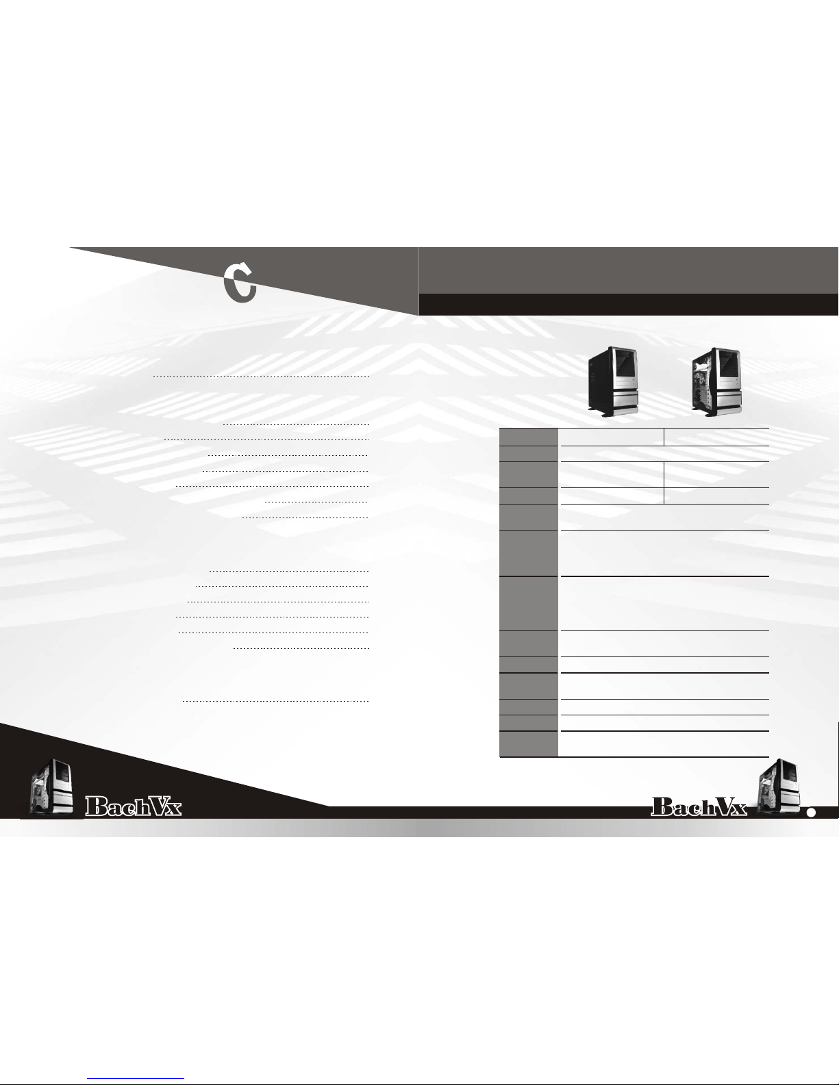
9.24 kg ; 20.37 lb
Transparent Side
Window
VF4000BWS
USB 2.0 x 2, eSATA connector x 1,
Standard ATX PSII
7
Black
Front panel : Aluminum
Body : 0.8mm SECC
497.0 x 210.0 x 475.0 mm ;
19.57 x 8.27 x 18.7 inch
-
Middle Tower
VF4000BNS
PSU
I/O Ports
Expansion
Slots
Color
Material
Drive Bays
- Front
accessible
- Internal
Cooling
System
Dimension
(H*W*D)
Side Panel
Motherboard
Net Weight
Case Type
Model
Net Weight 9.46 kg ; 20.85 lb
-
12" x 9.6" (ATX) & 9.6" x 9.6" (Micro ATX)
11
4 x 5.25", 2 x 3.5"
5 x 3.5"
Front (intake) : 140x140x25mm,
1000rpm, 16dBA
Rear (exhaust) : 120x120x25mm,
1000rpm, 15dBA
HD(High Definition) Audio
TM
4.1 Silent Purepower
ontents
VF4000 Series
1
Page 3
VF4000 Series
User's Manual
VF4000 Series
User's Manual
Chapter2 Case Mechanical Operation
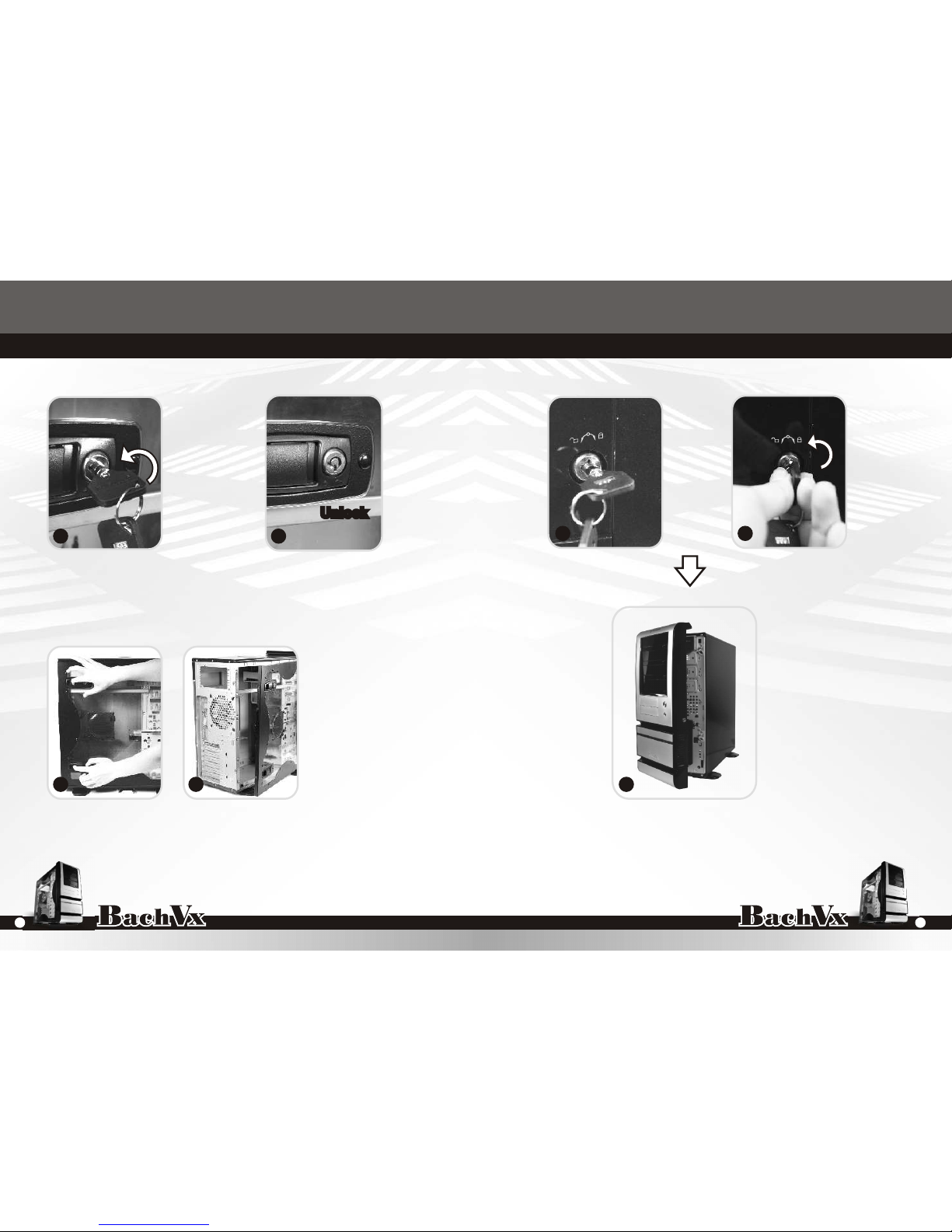
2.1 How to open the side panel
2.2 Lock operation
Turn it counterclockwise
O
90 to open the whole front panel.
Unlock
Push the button then swing out the side panel.
Make sure the side panel
lock is opened.
To find out the side panel
key from the back side of
the case then open it as
the picture.
’’
’’
1
2
3
5
6
7
4
Locked Insert the provided key and
turn it counterclockwise.
3
2
Page 4
VF4000 Series
User's Manual
VF4000 Series
User's Manual
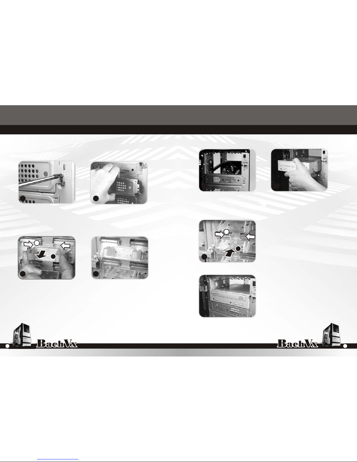
2.3 5.25" device installation
Unscrew the 5.25" drive bay metal cover.
Squeeze and pull out-ward the tool-free clip
Insert the device into the 5.25" drive bay.
Squeeze and push in-ward the
tool-free clip.
Finish installation
1
2
3
4
5 6
7
8
A
B
A
B
5
4
Page 5

VF4000 Series
User's Manual
VF4000 Series
User's Manual
2.4 3.5" device installation
1
2
3
4
5 6
7
Remove the 3.5" drive bay metal cover. Finish installation.
Unscrew and remove the 3.5" plastic cover. Place 3.5" device to the
drive bay.
Fasten the device on cage by
included thumb screws.
7
6
Page 6

VF4000 Series
User's Manual
VF4000 Series
User's Manual
2.5 HDD installation
Unscrew the thumb screw at the
bottom side of the cage.
Push the handle down and pull the cage out.
Slide the HDD into the
drive bay.
Slide the cage into drive bay
then screw up the thumb screw
at the bottom side of the cage.
Notice:
Bach Dx is compatible with graphic cards as long as
12.2" while removing the HDD cage. Card holder upgrade
kit is optional.
1
2 3
4
5
6
Screw up and fasten
HDD by screws on the
cage.
9
8
Page 7

VF4000 Series
User's Manual
VF4000 Series
User's Manual
2.7 Fan filter removal and cleaning
Front-Fan Filter
2
Firstly, open up the whole front panel.
2.6 PCI slot tool-free function operation
Open the plastic clip then take off the PCI bracket as shown.
Locate Graphic Card to the motherboard through
fixing it on the space of PCI bracket and secure
the Graphic Card.
1
2
3 4
1
2
3
Take off the fan grille, then
the filter can be removed.
11
10
Page 8

VF4000 Series
User's Manual
VF4000 Series
User's Manual
3-2 Case LED connection
On the front of the case, you can find some LEDs and
switch leads (POWER SW*1, POWER LED*1, H.D.D.
LED*1, RESET SW*1, Speaker*1). Please consult user
manual of your motherboard manufacturer, then connect
theseleads to the panel header on the motherboard.
Theseleads are usually labeled; if not, please trace them
back to the case front to find out their source.
- POWER LED
connects to your M/B at the PLED
- POWER SW
connects to the PWR connector on the motherboard.
- H.D.D LED
connects to the 2-pin labeled HDD LED connector.
- RESET SW
connects to the RSW connector on the motherboard
- SPEAKER
connector: find out the 4-pin labeled SPEAKER on the
M/B then connect it.
Chapter3 Motherboard & Leads Installation
3-1 Motherboard installation
Each motherboard has different standoff layout. It is highly
suggested that you refer to your motherboard's manual when
installing motherboard into the Case. The cases are applicable
with Standard ATX and Micro ATX. Your motherboard may
require a special I/O Panel, which should be included with your
motherboard.
Placement Direction:
When installing the motherboard, make sure you follow the
direction provided by your motherboard manufacturer. On most
standard motherboards, the edge with external ports goes to the
rear part of the chassis. It is highly recommended that you
install CPU, heat sink and modular components before fixing the
motherboard inside the chassis.
= the locations of
the screw holes. Note
these locations and
place included
standoffs on the chassis
first.
This side
towards
the rear of
the chassis
Above illustration is a sample of what the
motherboard's layout. For more detail screw
hole placement, please refer to your
motherboard manual.
LGA775
13
12
Page 9

VF4000 Series
User's Manual
VF4000 Series
User's Manual
3-4 Audio connection
Please refer to the following illustration of Audio
connector and your motherboard user manual.
Please select the motherboard which used AC'97 or HD
Audio (Azalia), (be aware of that your audio supports AC'97
or HD Audio (Azalia)) or it will damage your device(s).
On some motherboards, the connectors for Audio are not
the same as the drawing below. Please check with your
motherboard manual before installing.
PRESENCE#BLACK
SENSE1_RETURN
AUD GND
SENSE2_RETURN
YELLOW
BROWN
RED
PORT1 R
PORT2 R
PORT1 L
BLUE
PORT2 L
SENSE_SEND
KEY
PURPLE
GREEN
AUDIO AZALIA Function
ORANGE
BLACK
GROUND
Front
Audio Ground
L-RET
Rear Left Channel
Audio Signal
Rear Right Channel
Audio Signal
R-RET
NCBROWN
REDMIC IN
MIC POWER
Front Microphone
Power
Front Microphone
input Signal
KEY
BLUE
NC
BLUE
L-OUT
Front Left Channel
Audio Signal
Front Right Channel
Audio Signal
YELLOWR-OUT
AUDIO AC'97 Function
BLACK
YELLOW
3-3 USB 2.0 connection
2.5 Installing 3.5 HDD
Please consult your motherboard manual to find
out the section of "USB connection".
USB connection
1
2
3
5
4
6
7
8
USB2.0 connection
M/B layout (Ex: ASUS) Case layout
USB+5V
LDM1
LDP1
GND
NC
USB+5V
LDM2
LDP2
GND
--
VCC 1
Red
DATA-1
White
DATA+1
Green
GND 1
Black
SHIELD 1
Black
VCC 2
Red
DATA-2
White
DATA+2
Green
GND 2
Black
SHIELD 2
Black
USB 1
USB 2
9
10
15
14
Page 10

VF4000 Series
User's Manual
VF4000 Series
User's Manual
TM TM
The Thermaltake Silent Purepower specification meets Intel
Pentium 4 and AMD K8; it offers plenty of functions, which mainly
include:
TM
1.Automatic Fan Speed Control: The Silent Purepower power
supply can detect the inside heat and automatically adjust the
fan speed to provide adequate airflow.
2.Ultra Silent:Ball bearing fans with high reliability and super low
acoustic noise under all load condition.
TM
The functions can assure the Silent Purepower meet the balance
TM
in noise control and heat exhausted. The Silent Purepower provides
complete protection function as follow:
1.Over thermal protection at 100oC-105oC
2.Short circuit protection on all output.
3.Over voltage protection / Under voltage protection.
4.Over current protection.
Besides, Thermaltake enables the quality assurance of the Silent
TM
Purepower : 100% Hi-POT and ATE Function Test, 100% Burn-In and
AC Input cycled on/off under high temperature condition. Furthermore,
it has been approved by UL, CSA, TUV, VDE, NODIC, CB, FCC, CE, CNS.
There are three main products of Thermaltake PSU, it is divided into
standard, VR and specialty power supply unit. Please refer to
http://www.thermaltake.com/purepower/main.htm
TM
4-1 Silent Purepower
power supply (optional)
Chapter4 Other
3-5 eSATA connection
Connect this to your
motherboard at SATA.
3-6 Intrusion open alarm function
1
2
To find out the cable with 2pin
connector ("Micro SW") from the
rear of inside the chassis.
To find out the position of Chassis
Alarm on your motherboard.
(please consult your motherboard
manual)
White Wire
Black Wire
Note:
If you cannot find an intrusion alert function on your
motherboard, chances are high that your motherboard
does not support this function. Please tuck away this
wire and do not utilize this function.
17
16
Page 11

VF4000 Series
User's Manual
VF4000 Series
User's Manual
Page 12

VF4000 Series
User's Manual
VF4000 Series
User's Manual
 Loading...