

Page 1

INSTALLATION, OPERATING AND
SERVICE INSTRUCTIONS FOR
SOLARIS
Gas-Fired Boiler
For service or repairs to boiler, call your heating contractor. When seeking information on boiler,
provide Boiler Model Number and Serial Number as show on Rating Label.
Boiler Model Number
SOL __ __ __ __ - __ __ __
Heating Contractor Phone Number
Address
814SOL0010-8/09
Boiler Serial Number
6 __ __ __ __ __ __ __
Installation Date
Price - $5.00
1
Page 2

IMPORTANT INFORMATION - READ CAREFULLY
NOTE: The equipment shall be installed in accordance with those installation regulations enforced in the area where the
installation is to be made. These regulations shall be carefully followed in all cases. Authorities having jurisdiction
shall be consulted before installations are made.
All wiring on boilers installed in the USA shall be made in accordance with the National Electrical Code and/or local regulations.
All wiring on boilers installed in Canada shall be made in accordance with the Canadian Electrical Code and/or local regulations.
The Commonwealth of Massachusetts requires this product to be installed by a licensed Plumber or Gas Fitter.
The following terms are used throughout this manual to bring attention to the presence of hazards of various risk levels,
or to important information concerning product life.
DANGER
Indicates an imminently hazardous situation
which, if not avoided, will result in death,
serious injury or substantial property dam-
Indicates a potentially hazardous situation
which, if not avoided, may result in moderate or minor injury or property damage.
CAUTION
age.
WARNING
Indicates a potentially hazardous situation
which, if not avoided, could result in death,
serious injury or substantial property damage.
Indicates specic instructions on installation, operation, or maintenance which are
important but not related to personal injury
hazards.
NOTICE
DANGER
DO NOT store or use gasoline or other ammable vapors or liquids in the vicinity of this or any
other appliance.
If you smell gas vapors, DO NOT try to operate any appliance - DO NOT touch any electrical
switch or use any phone in the building. Immediately, call the gas supplier from a remotely located phone, Follow the gas supplier’s instructions or if the supplier is unavailable, contact the
re department.
Manufacturer’s Contact Information:
Thermal Solutions
1175 Manheim Pike
Lancaster, PA 17601
717-239-7642
www.thermalsolutions.com
2
Page 3

WARNING
This boiler requires regular maintenance and service to operate safely. Follow the instructions
contained in this manual.
Improper installation, adjustment, alteration, service or maintenance can cause property dam-
age, personal injury or loss of life. Read and understand the entire manual before attempting
installation, start-up operation, or service. Installation and service must be performed only by an
experienced, skilled, and knowledgeable installer or service agency.
This boiler must be properly vented.
This boiler needs fresh air for safe operation and must be installed so there are provisions for
adequate combustion and ventilation air.
The interior of the venting system must be inspected and cleaned before the start of the heating
season and should be inspected periodically throughout the heating season for any obstructions.
A clean and unobstructed venting system is necessary to allow noxious fumes that could cause
injury or loss of life to vent safely and will contribute toward maintaining the boiler’s efciency.
Installation is not complete unless a pressure relief valve is installed into the tapping located on
top of appliance. - See the Water Piping and Trim Section of this manual for details.
This boiler is supplied with safety devices which may cause the boiler to shut down and not restart without service. If damage due to frozen pipes is a possibility, the heating system should
not be left unattended in cold weather; or appropriate safeguards and alarms should be installed
on the heating system to prevent damage if the boiler is inoperative.
This boiler contains very hot water under high pressure. Do not unscrew any pipe ttings nor
attempt to disconnect any components of this boiler without positively assuring the water is cool
and has no pressure. Always wear protective clothing and equipment when installing, starting
up or servicing this boiler to prevent scald injuries. Do not rely on the pressure and temperature
gauges to determine the temperature and pressure of the boiler. This boiler contains components which become very hot when the boiler is operating. Do not touch any components unless
they are cool.
Boiler materials of construction, products of combustion and the fuel contain alumina, silica,
heavy metals, carbon monoxide, nitrogen oxides, aldehydes and/or other toxic or harmful substances which can cause death or serious injury and which are known to the state of California
to cause cancer, birth defects and other reproductive harm. Always use proper safety clothing,
respirators and equipment when servicing or working nearby the appliance.
Failure to follow all instructions in the proper order can cause personal injury or death. Read all
instructions, including all those contained in component manufacturers manuals which are provided with the boiler before installing, starting up, operating, maintaining or servicing.
Keep boiler area clear and free from combustible materials, gasoline and other ammable vapors or liquids.
All cover plates, enclosures and guards must be in place at all times.
This product must be installed by a licensed plumber or gas tter when installed within the Com-
monwealth of Massachusetts.
This boiler has a limited warranty, a copy of which is printed on the back of this manual. It is the
responsibility of the installing contractor to see that all controls are correctly installed and are
operating properly when the installation is complete.
NOTICE
3
Page 4

Table of Contents
I. Pre-Installation ................................................. 6
II. Unpack Boiler ...................................................7
III. Venting/Air Intake Piping ................................ 8
A. Vent Guidelines Due to Removal of an
Existing Boiler .............................................8
B. General Guidelines ..................................... 9
C. Supplemental Vent Terminal Location
Instructions ................................................10
D. Separate Horizontal Venting
System ........................................................ 11
E. Optional Horizontal Vent Terminal
Mounting .................................................... 14
F. Conventional Venting........ ........................15
G. Air Intake Piping ......................................15
H. Separate Vertical Venting System ...........17
IV. Water Piping and Trim .................................. 20
V. Gas Piping .......................................................24
VI. Electrical .........................................................26
VII. Modular Installations ....................................29
VIII. System Start-up ...........................................39
IX. Service and Maintenance ............................... 46
A. Periodic Maintenance ..............................46
B. Safety & Operating Controls .................... 49
C. Trouble Shooting ........................................50
X. Sage Boiler ControlTM (SBCTM)......................52
A. Introduction ............................................... 52
B. Front Panel Display ...................................53
C. Setup Menu ................................................54
D.BoilerCongurationMenu ......................56
E. SystemCongurationMenu ....................57
F. Setpoints Menu ..........................................58
G. Communication Menu ..............................59
H. Manual Mode Menu .................................. 59
I. Security Menu............................................60
XI. Repair Parts ....................................................61
XII. Service Record .............................................. 71
XIII. Refractory Ceramic Fiber ..........................74
XIV. Warranty .......................................................75
Minimum Clearance to Combustible Materials
Left Side Right Side Front Rear Top Flue Connector
1” 1” 24” 3” 1” 6”
Recommended Clearance for Service
Model Left Side or Right
Front Rear Top
Side
SOL-300 24” 24” 24” 16”
SOL-750 24” 24” 24” 16”
SOL-1000 24” 24” 24” 19”
SOL-1250 24” 24” 24” 31”
SOL-1500 24”
Note: Verify clearance with jurisdiction having authority and local codes.
4
Page 5
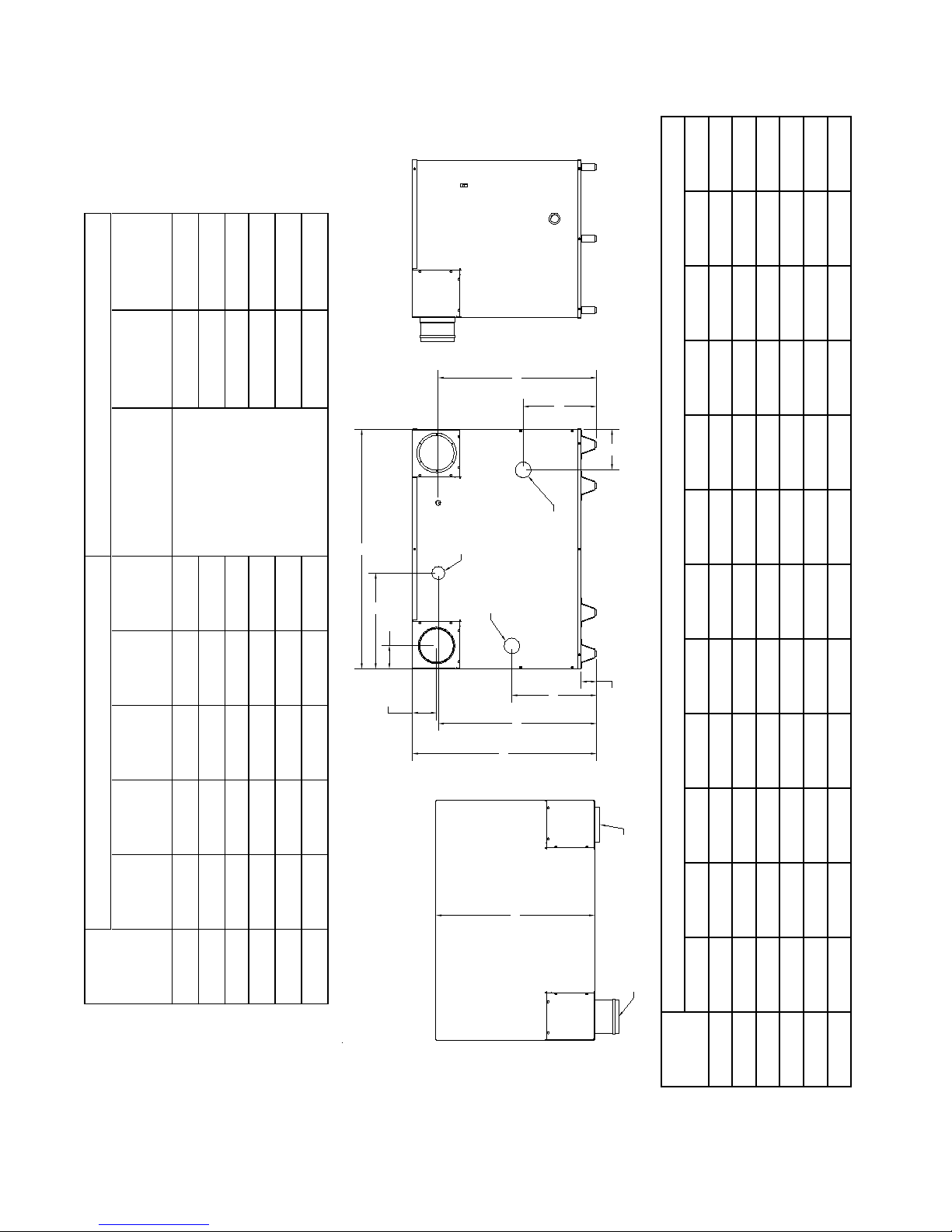
(Amps)
REAR VIEW
TOP VIEW
SIDE VIEW
L
(TYP.)
L
(TYP.)
C
2.71
E
D
B
K
A
13.00
H
M VENT
OUTLET
F OULET
WATER
F INLET
WATER
G INLET GAS
J
M VENT
INLET
Amp Draw
Rated Blower
(HP)
Rated Motor
Horse Power
Electrical Supply
(Voltz/Hertz/Phase)
Wet
(lbs.)
Weight
Dry
(lbs.)
Weight
Water
Volume
(Gallons)
BTU
(MBH)
Output
General Ratings and Capacities
(MBH)
BTU Input
Boiler
Model
SOL-300 300 252 1.1 288.5 297.7 3/4 8.5
SOL-500 500 420 1.3 316.0 326.8 3/4 8.5
SOL-750 750 637.5 2.4 508.5 528.5 120/60/1 3/4 8.0
SOL-1000 1000 850 2.6 548.5 570.2 3/4 8.0
SOL-1250 1250 1062.5 2.9 620.0 644.2 1-1/8 12
SOL-1500 1500 1275 3.3 713.0 740.5 1-1/8 12
Dimensions
‘A’ ‘B’ ‘C’ ‘D’ ‘E’ ‘F’ ‘G’ ‘H’ ‘J’ ‘K’ ‘L’ ‘M’
Boiler
Model
SOL-300 27.8 32.6 28.1 25.9 15.0 2.0 1.00 4.1 29.3 17.0 4.1 4.0
SOL-500 42.6 32.6 28.1 28.0 15.0 2.0 1.00 7.2 27.8 17.0 4.1 6.0
SOL-750 41.4 36.9 31.8 32.4 13.0 3.0 1.00 3.5 32.1 23.6 6.2 8.0
SOL-1000 49.4 36.9 31.8 32.4 13.0 3.0 1.25 3.5 32.1 21.6 6.2 8.0
SOL-1250 61.6 36.9 31.8 32.4 13.0 3.0 1.25 3.5 32.1 26.5 6.2 10.0
Figure 1: Dimensions
SOL-1500 73.9 36.9 31.8 32.4 13.0 3.0 1.50 3.5 32.1 25.6 6.2 10.0
5
Page 6

I. Pre-Installation
WARNING
If you do not follow these instructions ex-
actly, a re or explosion may result causing
property damage or personal injury.
DANGER
Do not install boiler where gasoline or other
ammable vapors or liquids, or sources
of hydrocarbons (i.e. bleaches, cleaners,
chemicals, sprays, paint removers, fabric
softeners, etc.) are used or stored.
NOTICE
E. Protect gas ignition system components from water
(dripping, spraying, rain, etc.) during boiler operation
and service (circulator replacement, condensate trap,
control replacement, etc.).
F. Provide combustion and ventilation air in accordance
with sections 5.3 of the National Fuel Gas code,
ANSIZ223.1/NFPA 54, or sections 7.2, 7.3, or 7.4 of
CAN/CSA B149.1, Natural Gas and Propane Installation code, or applicable provisions of the local building
codes.
WARNING
Adequate combustion and ventilation air
must be provided to assure proper combustion.
Due to the low water content of the boiler,
mis-sizing of the boiler with regard to the
heating system load will result in excessive
boiler cycling and accelerated component
failure. Thermal Solutions DOES NOT
warrant failures caused by mis-sized boiler
applications. DO NOT oversize the boiler
to the system. Modular boiler installations
greatly reduce the likelihood of boiler oversizing.
A. Installation must conform to the requirements of the
authority having jurisdiction. In the absence of such
requirements, installation must conform to the Na-
tional Fuel Gas Code, NFPA 54/ANSI Z223.1, and/or
CAN/CGA B149 Installation Codes. Where required
the installation must conform to the standard for con-
trols and safety devices for automatically red boilers,
ANSI/ASME CSD-1.
B. Appliance is design certied for installation on combus-
tible ooring. Do not install boiler on carpeting.
C. Provide clearance between boiler jacket and combus-
tible material in accordance with local re ordinance.
Refer to Figure 1 for minimum listed clearance from
combustible material. Recommended service clearance
is 24 inches from left side, right side and front. Recommended service clearance is 36” at rear of unit. Service clearances may be reduced to minimum clearances
to combustible materials.
The following guideline is based on the National Fuel Gas
Code, NFPA 54/ANSI Z223.1.
1. Determine volume of space (boiler room). Rooms
communicating directly with space (through openings not furnished with doors) are considered part of
space.
Volume [ft³] = Length [ft] x Width [ft] x Height [ft]
2. Determine Total Input of all appliances in space.
Round result to nearest 1,000 Btu per hour (Btuh).
3. Determine type of space. Divide Volume by Total
Input.
a. If result is greater than or equal to 50 ft³ per
1,000 Btuh, space is considered an unconned
space.
b. If result is less than 50 ft³ per 1,000 Btuh, space
is considered a conned space.
4. Determine building type. A building of unusually
tight construction has the following characteristics:
a. Walls and ceiling exposed to outside atmosphere
have a continuous water vapor retarder with a
rating of 1 perm or less with openings gasketed
and sealed, and;
b. Weather-stripping has been added on openable
windows and doors, and;
c. Caulking or sealants applied in joints around
window and door frames, between sill plates and
oors, between wall-ceiling joints, between wall
panels, at plumbing and electrical penetrations,
and at other openings.
D. Install on level oor. Floor must be able to support
weight of boiler, water and all additional system components.
6
Page 7
5. For boiler located in an unconned space in a
building of other than unusually tight construction, adequate combustion and ventilation air
is normally provided by fresh air inltration
through cracks around windows and doors.
6. For boiler located within unconned space in
building of
within equate conned space, provide outdoor
air through two permanent openings which
communicate directly or by duct with the
outdoors or spaces (crawl or attic) freely commu nicating with the outdoors. Locate one opening
within twelve (12) inches of top of space. Locate
remaining opening within twelve (12) inches of
bottom of space. Minimum dimension of air
opening is three (3) inches. Size each opening
per following:
a. Direct communication with outdoors. Minimum
free area of one (1) square inch per 4,000 Btu per
hour input of all equipment in space.
b. Vertical ducts. Minimum free area of one (1)
square inch per 4,000 Btu per hour input of all
equipment in space. Duct cross-sectional area
shall be same as opening free area.
c. Horizontal ducts. Minimum free area of one (1)
square inch per 2,000 Btu per hour input of all
equipment in space. Duct cross-sectional area
shall be same as opening free area.
unusually tight construction, or
Alternate method for boiler located within
conned space. Use indoor air if two permanent
openings communicate directly with additional
space(s) of sufcient volume such that combined
volume of all spaces meet criteria for unconned
space. Size each opening for minimum free area
of one (1) square inch per 1,000 Btu per hour
input of all equipment in spaces, but not less than
100 square inches.
7. Combustion Air/Ventilation Duct Louvers and
Grilles. Equip outside openings with louvers to
prevent entrance of rain and snow, and screens to
prevent entrance of insects and rodents. Louvers and
grilles must be xed in open position or interlocked
with equipment to open automatically before burner
operation. Screens must not be smaller than ¼ inch
mesh.
Consider the blocking effect of louvers, grilles and
screens when calculating the opening size to provide
the required free area. If free area of louver or grille
is not known, assume wood louvers have 20-25
percent free area and metal louvers and grilles have
60-75 percent free area.
CAUTION
Avoid operating this boiler in an environment where saw dust, loose insulation bers, dry wall
dust, etc. are present. If boiler is operated under these conditions, the burner interior and ports
must be cleaned and inspected daily to insure proper operation.
II. Unpack Boiler
CAUTION
Do not drop boiler. Do not bump boiler
jacket against the oor.
A. Move boiler to approximate installed position.
B. Remove all crate fasteners.
C. Lift and remove outside container. Save two of the
wooden slats from the container sleeve for use in Steps
E and F.
D. Remove all boiler hold-down fasteners.
Installation of this boiler should be undertaken only by trained and skilled personnel
from a qualied service agency.
E. Tilt the boiler to its front side or back side and slide a
wooden slat under the raised feet.
F. Tilt the boiler in the opposite direction and slide another
wooden slat under the raised feet.
G. Slide the boiler left or right off the skid using the two
wooden slats as runners.
H. Move boiler to its permanent location.
WARNING
7
Page 8
III. Venting / Air Intake Piping
WARNING
Do not use this boiler with galvanized, non metallic or any other venting material that is not de-
signed for condensing ue gas applications.
Do not use a drafthood with this appliance.
Do not use vent dampers with this boiler.
Moisture and ice may form on surfaces around termination. To prevent deterioration, surfaces
should be in good repair (sealed, painted, etc.).
This appliance needs fresh air for safe operation and must be installed so there are provisions
for adequate combustion and ventilation air.
Do not reduce size of air intake pipe.
Read, understand and follow combustion air instruction restrictions contained in the Pre-Installa-
tion instructions of this manual.
Do not operate appliance where gasoline or other ammable vapors or liquids, or sources of
hydrocarbons (i.e. bleaches, cleaners, chemicals, sprays, paint removers, fabric softeners, etc.)
are used, stored and/or present in the air.
When installing vent pipe through chimney, no other appliance can be vented into the chimney.
Do not exceed maximum vent/air intake lengths. Refer to Table 1.
A. Vent Guidelines Due to Removal of an Ex-
isting Boiler
For installations not involving the replacement of an
existing boiler, proceed to Step B.
When an existing boiler is removed from a common
venting system, the common venting system is likely to
be too large for proper venting of the remaining appliances. At the time of removal of an existing boiler, the
following steps shall be followed with each appliance
remaining connected to the common venting system
placed in operation, while the other appliances remaining connected to the common venting system are not in
operation:
1. Seal any unused openings in the common venting
system.
2. Visually inspect the venting system for proper size
and horizontal pitch and determine there is no
blockage or restriction, leakage, corrosion, and
other deciencies which could cause an unsafe
condition.
3. Insofar as is practical, close all building doors and
windows and all doors between the space in which
the appliances remaining connected to the common
venting system are located and other spaces of the
building. Turn on clothes dryers and any appliance
not connected to the common venting system.
Turn on any exhaust fans, such as range-hoods
and bathroom exhausts, so they will operate at
8
maximum speed. Do not operate a summer exhaust
fan. Close replace dampers.
4. Place in operation the appliance being inspected.
Follow the Lighting (or Operating) Instructions.
Adjust thermostat so appliance will operate
continuously.
5. Test for spillage at the draft hood relief opening
after ve (5) minutes of main burner operation. Use
the ame of a match or candle, or smoke from a
cigarette, cigar or pipe.
6. After it has been determined that each appliance
remaining connected to the common venting
system properly vents when tested as outlined
above, return doors, windows, exhaust fans, re
place dampers and any other gas burning appliance
to their previous conditions of use.
7. Any improper operation of the common venting
system should be corrected so the installation
conforms with the National Fuel Gas Code, NFPA
54/ANSI Z223.1 and/or CAN/CSA B149.1 Natural
Gas and Propane Installation Code. When resizing
any portion of the common venting system, the
common venting system should be resized to approach the minimum size as determined using the
appropriate tables in Part 11 of the National Fuel
Gas Code, ANSI Z223.1/NFPA 54 and/or CAN/CSA
B149.1 Natural Gas and Propane Installation Code.
Page 9

B. General Guidelines
1. Vent system installation must be in accordance with
Part 7, Venting of Equipment of the National Fuel
Gas Code, ANSI Z223.1/NFPA 54, or Section 7,
Venting Systems and Air Supply for Appliances of
the CAN/CSA B149.1, Natural Gas and Propane Installation Code, or applicable provisions of the local
building codes.
2. Contact local building or re ofcials about restrictions and installation inspection in your area.
3. Refer to the appropriate drawings in this section of
this manual to determine the proper conguration of
venting system. Figures 2 thru 11. The vent system
shall be installed in accordance with the instructions
listed in this manual.
4. This appliance requires a Special Gas Vent. The
product is designed to use AL 29-4C® Stainless
Steel or other Stainless Steel material approved for
condensing ue gas applications. The boilers are
shipped with AL 29-4C® vent adapter to directly
connect to Heat Fab Saf-T-Vent. The use of alternate manufacturer’s venting systems will require
adapters and vent terminal. These adapters are not
supplied with this unit and should be obtained from
the supplier of alternate venting system.
5. The venting system must be installed so as to
prevent accumulation of condensate. Horizontal
vent pipe must maintain a minimum ¼ inch per foot
slope down towards boiler.
a. Do not manifold condensate drains.
b. A common condensate pump/sump may be used.
Run separate condensate piping from each vent
drain to the sump. A common drain may be used
to discharge condensate from the sump.
Consult pump/sump manufacturer for compat-
ibility of materials of construction with ue gas
condensate. If a common pump/sump is used,
individual vent drain lines must be connected
such that one drain pipe cannot back feed into
another vent drain.
c. Consult local authorities regarding disposal of
ue gas condensate into public waste water system. Some jurisdictions require that the condensate be buffered before discharge. this buffering
is commonly achieved by draining the condensate through a limestone bed. Consult chemical
treatment company for buffering systems.
6. Use noncombustible ¾ inch pipe strap to support
horizontal runs and maintain vent location and
slope while preventing sags in pipe. Do not restrict
thermal expansion or movement of vent system.
Maximum support spacing is ve (5) feet. Do not
penetrate any part of the vent system with fasteners.
7. Vent length restrictions are based on equivalent
length of vent/air pipe (total length of straight
pipe plus equivalent length of ttings). Maximum
vent/air lengths are listed in Table 1. Do not exceed
Table 1: Vent & Air Intake Length
Vent/Air Intake
Pipe Dia.Min Max
Boiler Model
SOL-300 5 50 4
SOL-500 5 78 6
SOL-750 5 50 8
SOL-1000 5 50 8
SOL-1250 5 50 10
SOL-1500 5 50 10
maximum vent/air intake lengths. Refer to vent
manufacturer’s recommendations for the equivalent
length of ttings.
8. Provide and maintain vent pipe minimum clearances
to combustible materials. Vent pipe minimum clearance to combustible material is four (4) inches when
vent is installed in a fully enclosed (chase) application or three (3) inches when vent is installed with
at least one side open, similar to a joist bay application. Use double wall thimble when penetrating a
combustible wall. Some examples of Wall thimble
manufactures are American Metal Products, Hart &
Cooley, and Metal Fab.
9. Do not install venting system components on the ex-
terior of the building except as specically required
by these instructions. The vent termination location
is restricted as follows:
a. The minimum distance from adjacent public
walkways, adjacent buildings, openable win
dows and building openings shall not be less
than those values specied in the National Fuel
Gas Code, ANSI Z223.1/NFPA 54 and/or CAN/
CSA B149.1, Natural Gas and Propane Installa
tion Code.
b. Minimum twelve (12) inches above grade plus
normally expected snow accumulation level, or
seven (7) feet above grade if located adjacent to
public walkway. Do not install over public walkway where local experience indicates appliance
ue gas vapor or condensate creates a nuisance
or hazard.
c. Minimum three (3) feet above any forced air
inlet located within ten (10) feet.
d. Power Vent - Minimum four (4) feet below, four
(4) feet horizontally from, or four (4) feet above
any door, window, or gravity air inlet.
ft. ft. In.
9
Page 10

e. Minimum of four (4) feet horizontally from, and
in no case above or below, unless a 4 foot horizontal distance is maintained from electric meters, gas meters, regulators and relief equipment.
This distance may be reduced if equipment is
protected from damage due to condensation or
vapor by enclosure, overhangs, etc.
f. Minimum twelve (12) inches from overhang or
corner of building.
g. The vent termination shall be located such that
no damage to building materials will occur from
Figure 2: Vent Therminal Location
NOTICE
Cut must be square with pipe and led or
sanded smooth before joining. Carefully
ensure roundness of cut pipe by hand with
gloves before installing. Seal joint with RTV
specied in this manual.
ue gasses degradation.
10. Enclose vent passing through occupied or unoccu
pied spaces above the boiler with material having a
re resistance rating of at least equal to the rating
of the adjoining oor or ceiling. Maintain minimum
clearances to combustible materials. See page 4.
11. Plan venting system to avoid possible contact with
plumbing or electrical wires. Start at vent connector
on top of boiler and work towards vent terminal.
12. Once a vent pipe manufacturer and system is chosen never mix and match vent systems.
13. Field Supplied Vent Terminations (One per boiler)
a. Horizontal - Use Saf-T Vent mitered termination
with screen or equivalent
b. Vertical - Use Saf-T Vent rain cap or equivalent
C. Supplemental Vent Terminal Location In-
structions (Massachusetts Code Only)
The Commonwealth of Massachusetts requires compli-
ance with regulation 248 CMR 4.00 and 5.00 for installation of side-wall vented gas appliances as follows:
(a) For all side wall horizontally vented gas fueled equip-
ment installed in every dwelling, building or structure
used in whole or in part for residential purposes, including those owned or operated by the Commonwealth and
where the side wall exhaust vent termination is less than
seven (7) feet above nished grade in the area of the
venting, including but not limited to decks and porches,
the following requirements shall be satised:
1. INSTALLATION OF CARBON MONOXIDE DETECTORS. At the time of installation of the side wall
horizontal vented gas fueled equipment, the installing
plumber or gastter shall observe that a hard wired
carbon monoxide detector with an alarm and battery
back-up is installed on the oor level where the gas
equipment is to be installed. In addition, the install-
ing plumber or gastter shall observe that a battery
operated or hard wired carbon monoxide detector with
an alarm is installed on each additional level of the
dwelling, building, or structure served by the side wall
horizontal vented gas fueled equipment. It shall be the
responsibility of the property owner to secure the services of qualied licensed professionals for the installation of hard wired carbon monoxide detectors.
a. In the even that the side wall horizontally vented
gas fueled equipment is installed in a crawl space or
an attic, the hard wired carbon monoxide detector with
alarm and battery back-up may be installed on the next
adjacent oor level.
b. In the event that the requirements of this subdivision
can not be met at the time of completion of installation, the owner shall have a period of thirty (30) days
to comply with the above requirements; provided, however, that during said thirty (30) day period, a battery
operated carbon monoxide detector with an alarm shall
be installed.
2. APPROVED CARBON MONOXIDE DETECTORS.
Each carbon monoxide detector as required in accordance with the above provisions shall comply with
NFPA 720 and be ANSI/UL 2034 listed and IAS certi-
ed.
3. SIGNAGE. A metal or plastic identication plate shall be
permanently mounted to the exterior of the building at
a minimum height of eight (8) feet above grade directly
in line with the exhaust vent terminal for the horizontally vented gas fueled heating appliance or equipment.
The sign shall read, in print size no less than one-half
(1/2) inch in size, “GAS VENT DIRECTLY BELOW,
KEEP CLEAR OF ALL OBSTRUCTIONS”.
4. INSPECTION. The state or local gas inspector of the side
wall horizontally vented gas fueled equipment shall
not approve the installation unless, upon inspection,
10
Page 11

the inspector observes carbon monoxide detectors and
signage installed in accordance with the provisions of
248 CMR 5.08(2)(a)1 through 4.
(b) EXEMPTIONS: The following equipment is exempt
from 248 CMR 5.08(2)(a)1 through 4:
1. The equipment listed in Chapter 10 entitled “Equipment Not Required To Be Vented” in the most current
edition of NFPA 54 as adopted by the board; and
2. Product Approved side wall horizontally vented
gas fueled equipment installed in a room or structure
separate from the dwelling, building or structure used in
whole or in part for residential purposes.
(c) MANUFACTURER REQUIREMENTS - GAS
EQUIPMENT VENTING SYSTEM PROVIDED.
When the manufacturer of Product Approved side wall
horizontally vented gas equipment provides a venting
system design or venting system components with the
equipment, the instructions provided by the manufacturer for installation of the equipment and the venting
system shall include:
1. Detailed instructions for the installation of the venting system design or the venting system components;
and
2. A complete parts list for the venting system design or
venting system.
(d) MANUFACTURER REQUIREMENTS - GAS
EQUIPMENT VENTING SYSTEM NOT PROVIDED.
When the manufacturer of a Product Approved side
wall horizontally vented gas fueled equipment does not
provide the parts for venting the ue gasses, but identies “special venting systems”, the following requirements shall be satised by the manufacturer:
1. The referenced “special venting system” instructions shall be included with the appliance or equipment
installation instructions; and
2. The “special venting systems” shall be Product
Approved by the Board, and the instructions for that
system shall include a parts list and detailed installation
instructions.
(e) A copy of all installation instructions for all Product
Approved side wall horizontally vented gas fueled
equipment, all venting instructions, all parts lists for
venting instructions, and/or all venting design instructions shall remain with the appliance or equipment at
the completion of the installation.
D. Separate Horizontal Venting System. See
Figures 3, 4 and 5.
1. Vent Piping –
a. Do not exceed maximum vent/air intake
lengths. Refer to Table 1.
b. Recommended horizontal installation consists
of vent being sloped down ¼ inch per foot
toward boiler.
c. Use appropriate designed thimbles when
passing through combustible walls (thimble
use optional for noncombustible walls). Insert
thimble through wall from outside. Secure
outside ange to wall with nails or screws, and
seal ID, OD and vent holes with sealant
material. Install inside ange to inside wall,
secure with nails or screws, and seal with
sealant material.
d. For noncombustible wall application when
thimble is not used, size opening such that bell
with locking band attached cannot pass
through.
e. Join vent terminal to vent pipe. Locate vent
pipe such that vent terminal is between six (6)
inches and twenty-four (24) inches from wall
when joined to inside vent piping. See Figure
3 or 4.
f. Insert vent pipe through thimble/opening from
outside and join to vent system. Apply seal ant between vent pipe and opening/thimble to
provide weathertight seal.
2. Side Vent Installation. See gure 5.
a. Horizontal vent/air intake runs with no
vertical rise in piping allowed.
b. Do not exceed maximum vent/air intake
lengths. Refer to Table 1.
c. Recommended Horizontal Installation only
consists of vent/air intake sloped down 1/4
inch per foot toward termination.
d. Thimbles, same as “C” above in section D.1
e. same as “D” above in section D.1
f. same as “E” above in section D.1
g. same as “F” above in section D.1
Figure 3: Side Top Vent
11
Page 12

12
Figure 4: Recommended Separate Horizontal - Vent/Air Intake Installation
Page 13

Figure 5: Side Vent
13
Page 14

E. Optional Separate Horizontal Vent Terminal Mounting – See Figure 6
1. Do not exceed maximum vent/air intake lengths.
Refer to Table 1.
2. This installation will allow a maximum of ve (5)
feet vertical exterior run of the vent/air intake piping
to be installed on separate horizontal venting and
indoor air horizontal venting.
Note: Exterior run to be included in equivalent vent/
air intake lengths.
3. Install vent piping.
a. Install vent piping for desired venting system.
Refer to specic section for details for vent pipe
installation.
b. After penetrating wall/thimble, install a 90°
elbow so that elbow leg is in the up direction.
c. Install maximum of ve (5) feet of vent pipe.
Refer to Sections C through E for proper proce-
dures for joining vent pipe and ttings.
d. At top of vent pipe length install a 90° elbow so
that elbow leg is opposite the building’s exterior
surface.
e. Install 45° elbow to upper 90° elbow so that leg
of 45° is in down direction (see Figure 6). If not
using indoor air, proceed to Step f.
f. Install horizontal vent terminal.
g. Brace piping if required.
4. Air Intake Piping (not required for indoor air).
a. Install air intake piping for desired venting sys-
tem. Refer to specic section for details for air
intake installation.
b. After penetrating wall, install a corrosion re-
sistant 90o elbow so that elbow leg is in the up
direction.
c. Install maximum of ve (5) feet of corrosion
resistant air intake pipe.
d. At top of air intake pipe install air intake termi
nal (provided with boiler).
e. Brace piping if required.
-
14
Figure 6: Optional Indoor Air – Vent Terminal Installation
Page 15
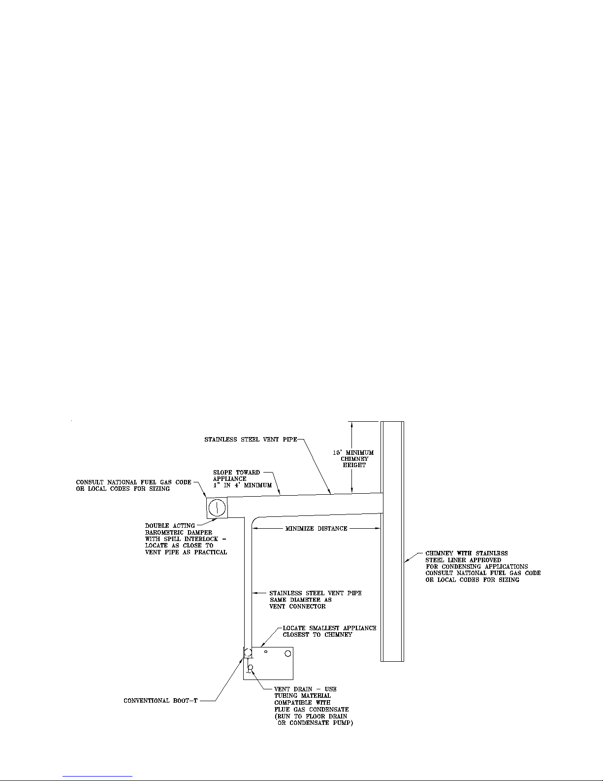
F. Conventional Venting (Negative Draft) – See Figure 7
a. The minimum chimney height is 15 feet.
b. The chimney must be protected from down
drafts, rain and debris by using a chimney cap or
star.
c. Start installing vent at vent cap and continue
installation toward the boiler.
d. The ue connector and chimney ue diameter
may need to be increased or decreased depend
ing on the dimensions of the boiler. Consult the
National Fuel Gas Code or Local Codes for siz-
ing. Boiler input, ue connector lateral distance
and chimney height affect the ue connector or
chimney ue diameters.
e. A double acting barometric damper with integral
ue spillage interlock switch must be used when
the boiler is vented conventionally.
f. The chimney and ue connector must be sized
and congured to provide a minimum - 0.04 inch
w.c. draft at the vent outlet of the boiler.
g. Maintain a minimum vertical pitch of one (1)
inch in four (4) feet of vent connector run.
G. Air Intake Piping - See Figure 4 & 8
1. Locate air intake termination on the same wall as the
vent termination if possible, to prevent nuisance boiler
shutdowns. However, boiler may be installed with vertical venting and sidewall combustion air inlet or vice
versa, if installation conditions do not allow alternate
arrangement.
2. Do not exceed maximum air intake length. See Table 1.
3. Use single wall metal pipe and ttings or thin wall PVC
available at most heating distributors.
4. Air intake termination must be located: Horizontal - At
least twelve (12) inches above grade plus the expected
snow accumulation.
5. Start at collar on burner enclosure (inside boiler jacket)
and work towards the air intake terminal.
6. Maintain minimum of 1/4 inch per foot slope on
horizontal runs. Slope towards air inlet terminal when
possible. If not, slope towards boiler.
7. The air intake pipe must be adequately supported with
straps or supports no less than ve (5) feet apart on
horizontal runs. The complete air intake piping system
must be rigid and able to withstand minor impacts without collapse.
8. Inlet air pipe penetration: Horizontal - Size wall penetration to allow easy insertion of air inlet piping. Seal
around pipe with sealant to form weathertight exterior
joint.
9. Seal all joints airtight, using silicone caulk or self-adhesive aluminum tape.
10. Install Air Intake Terminal.
Figure 7: Conventional Venting (Negative Draft)
15
Page 16

16
SEE TABLE 1.
Figure 8: Separate Horizontal – Vent/Air Intake Terminal Conguration
Page 17

H. Separate Vertical Venting System - See Figures 9, 10, and 11.
Vertical Venting –
1. Do not exceed maximum vent lengths. Refer to
Table 1.
2. Slope horizontal runs minimum ¼ inch per foot
down towards boiler.
3. Install re stops where vent passes through oors,
ceilings or framed walls. The re stop must close
the opening between the vent pipe and the structure.
Fire stop manufacturers are Air-Jet, American Metal
Products, Metal-Fab, and Simpson Dura-Vent.
4. Whenever possible, install vent straight through the
roof. Refer to Figure 9 if offset is necessary. Maintain minimum clearance to combustible
materials.
5. Install Vent Terminal.
a. Size roof opening to maintain minimum clear-
ance from combustible materials.
b. Extend vent pipe to maintain minimum vertical
and horizontal distance of twelve (12) inches
from roof surface. Allow additional vertical distance for expected snow accumulation. Provide
brace as required. Refer to Figure 11.
c. Vertical venting requires use of the roof ashing
and storm collar to prevent moisture from entering the structure.
d. Install storm collar on vent pipe immediately
above ashing. Apply Dow Corning Silastic 732
RTV Sealant between vent pipe and storm collar
to provide weathertight seal.
e. Attach vent terminal.
Vertical Air Intake Piping –
1. Do not exceed maximum air intake length. Refer to
Table 1.
2. Locate air intake termination on the same roof loca
tion as the vent termination if possible, to prevent
nuisance boiler shutdowns. However, boiler may be
installed with vertical venting and sidewall combustion air inlet or vica versa, if installation conditions
do not allow alternate arrangement.
-
8. Inlet air pipe penetration:
9. Seal all joints airtight, using silicone caulk or self -
adhesive aluminum tape.
10. Install Air Intake Terminal:
Vertical - Insert intake piping into intake terminal
collar. Secure terminal to intake piping and seal
joint with silicone caulk.
with straps or supports no less than ve (5) feet
apart on horizontal runs. The complete air intake
piping system must be rigid and able to withstand
minor impacts without collapse.
Vertical - Size roof opening to allow easy insertion
of inlet piping and allow proper installation of ashing and storm collar.
a. Use appropriately designed vent ashing when
passing through roofs. Follow ashing manufac-
turers’ instructions for installation procedures.
Flashing manufacturers are Air-Jet, American
Metal Products, Metal Fab, and Simpson DuraVent.
b. Extend air intake pipe to maintain minimum
vertical and horizontal distance of twelve (12)
inches from roof surface. Allow additional vertical distance for expected snow accumulation.
Provide brace as required. Refer to Figure 11.
c. Vertical air intake requires ashing and a storm
collar to prevent moisture from entering the
structure.
d. Install storm collar on air intake pipe immediate-
ly above ashing. Apply Dow Corning Silastic
732 RTV Sealant between air intake pipe and
storm collar to provide weathertight seal.
3 Use single wall metal pipe and ttings or thin wall
PVC available at most heating distributors.
4. Air intake termination must be located:
Vertical - At least twelve (12) inches above the roof
surface plus the expected snow accumulation.
5. Start at collar on burner enclosure (inside boiler
jacket) and work towards the air intake terminal.
6. Maintain minimum of 1/4 inch per foot slope on
horizontal runs. Slope down towards boiler.
7. The air intake pipe must be adequately supported
17
Page 18

18
Figure 9: Vertical Vent Installation
Page 19

Figure 10: Attic Offset
Figure 11: Indoor Air - Horizontal / Vertical Vent Terminal Installation
Extend Vent/Air Intake Piping to maintain minimum vertical (“X”) and minimum horizontal (“Y”) distance of twelve
(12) inches from roof surface. Allow additional vertical (“X”) distance for expected snow accumulation.
19
Page 20

IV. Water Piping and Trim
CAUTION
iii. Oxygen permeable materials in the distribu-
tion system.
Failure to properly pipe boiler may result in
improper operation and damage to boiler or
structure.
1. Design and install boiler and system piping to
prevent oxygen contamination of boiler water and
frequent water additions.
CAUTION
Oxygen contamination of boiler water will
cause corrosion of iron and steel boiler
components, and can lead to boiler failure. Thermal Solutions Standard Warranty
does not cover problems caused by oxygen contamination of boiler water or scale
(lime) build-up cause by frequent addition of
water.
CAUTION
All piping either new or existing must be
cleaned with a tri sodium phosphate (TSP)
solution to remove mill scale and oils from
the system. Failure to do so could result in
premature failure of the heat exchanger (not
covered by Thermal Solutions warranty.)
CAUTION
On an existing or retrot system, a lter or
strainer must be installed on the system
return prior to the boilers.
b. In order to insure long product life, oxygen
sources must be eliminated. This can be accomplished by taking the following measures:
i. Repairing system leaks to eliminate the need
for addition of make-up water.
ii. Eliminating and/or repairing ttings which
allow oxygen absorption.
iii. Using non-permeable materials in the distri-
bution system.
iv. Isolating the boiler from the system water by
installing a heat exchanger.
vi. Using properly designed and operating air
elimination devices in water piping.
2. Design and install system piping to prevent return
water temperatures below 130°F. Refer to Table 2
for boiler ow and pressure drop requirements.
3. Connect system supply and return piping to boiler.
Refer to Figure 12. Also consult I=B=R Installation
CAUTION
Return water temperature below 130°F
will cause ue gas condensation inside the
boiler. Flue gas condensate can lead to
boiler failure. Thermal Solutions Standard
Warranty does not cover problems caused
by ue gas condensation.
WARNING
CAUTION
When using Glycol products, all Glycol
manufacturers’ requirements, including
rust inhibitors, must be adhered. Max 50%
Glycol.
a. There are many possible causes of oxygen con-
tamination such as:
i. Addition of excessive make-up water as a
result of system leaks.
ii. Absorption through open tanks and ttings.
20
Supply and return water temperature differences greater than 40°F can lead to boiler
failure. Thermal Solutions Standard Warranty does not cover problems caused by
temperature difference greater than 40°F.
and Piping Guides. Maintain ½” minimum distance
between water piping and combustible material.
Consult Thermal Solutions for unusual system
requirements.
4. A pressure relief valve is supplied with each appliance. No valve is to be placed between the relief
valve and appliance. No reducing coupling or other
restriction shall be installed in the discharge line.
Page 21

See Figure 13.
compatible with local environmental regulations.
a. Pipe the safety relief discharge to a suitable place
for disposal when relief occurs.
b. Do not install reducing couplings for other
restrictive devices in the safety relief discharge
line.
c. The safety relief discharge line must allow for
complete drainage of both the valve and line.
5. If the relief valve discharges periodically, this may
be due to thermal expansion in a closed water
supply system. Contact the water supplier or local
plumbing inspector on how to correct this situation.
DO NOT PLUG THE RELIEF VALVE.
6. Install the drain valve provided with the appliance at
the lowest elevation. See Figure 13.
7. If this boiler is used in connection with refrigeration systems, the boiler must be installed so that the
chilled medium is piped in parallel with the boiler
using appropriate valves to prevent the chilled
medium from entering the boiler, see gure 13A.
Also consult I=B=R Installation and Piping Guides.
If this boiler is connected to heating coils located
in air handling units where they may be exposed to
refrigerated air circulation, the boiler piping must be
equipped with ow control valves or other automatic means to prevent gravity circulation of boiler
water during operation of the cooling system.
8. Install water ow switch. Water ow switch must
be located such that water ow disruptions do not
affect switch operation. Maintain maximum practi-
cal straight piping before and after ow switch to
minimize water disruptions. Refer to manufactures’
instructions for proper paddle length.
9. A low water cutoff is required to protect a hot water
boiler when any connected heat distributor (radiation) is installed below the top of the hot water
boiler (i.e. baseboard on the same oor level as the
boiler). In addition, some jurisdictions require the
use of a LWCO with a hot water boiler. If a low
water cutoff is required, it must be mounted in the
system piping above the boiler. The minimum safe
water level of a hot water boiler is just above the
highest water containing cavity of the boiler; that is,
a hot water boiler must be full of water to operate
safely.
10. Oil, grease, and other foreign materials which
accumulate in new hot water boilers and a new or
reworked system should be boiled out, and then
thoroughly ushed. A local qualied water
treatment chemical specialist is a suggested source
for recommendations regarding appropriate
chemical compounds and concentrations which are
11. After the boiler and system have been cleaned and
ushed, and before relling the entire system add
appropriate water treatment chemicals, if necessary,
to bring the pH between 8.8 and 9.2.
12. If it is required to perform a long term pressure
test of the hydronic system, the boiler should rst
be isolated to avoid a pressure loss due to the
escape of air trapped in the boiler.
To perform a long term pressure test including the
boiler, ALL trapped air must rst be removed from
the boiler.
A loss of pressure during such a test, with no
visible water leakage, is an indication that the
boiler contained trapped air.
WARNING
Failure to operate the unit with the proper
water ow rate can lead to appliance failure.
Always install water ow switch so that the
unit stops operating if improper water ow
is present.
Safety relief valve discharge piping must
be piped such that the potential of severe
burns is eliminated. DO NOT pipe in any
area where freezing could occur. DO NOT
install any shut-off valves, plugs or caps.
Consult Local Codes for proper discharge
piping arrangement.
Do not operate boiler with ow rates in
excess of the maximum ow rates listed in
Table 2. Boiler tube erosion and pitting will
occur. Thermal Solutions Standard Warranty does not cover problems caused by
excessive water ow rates.
If a high head system pump is installed, assure that the boiler relief valve and system
piping are capable of operating properly
at the combined pressure of the system ll
pressure plus the pump static head pressure.
21
Page 22
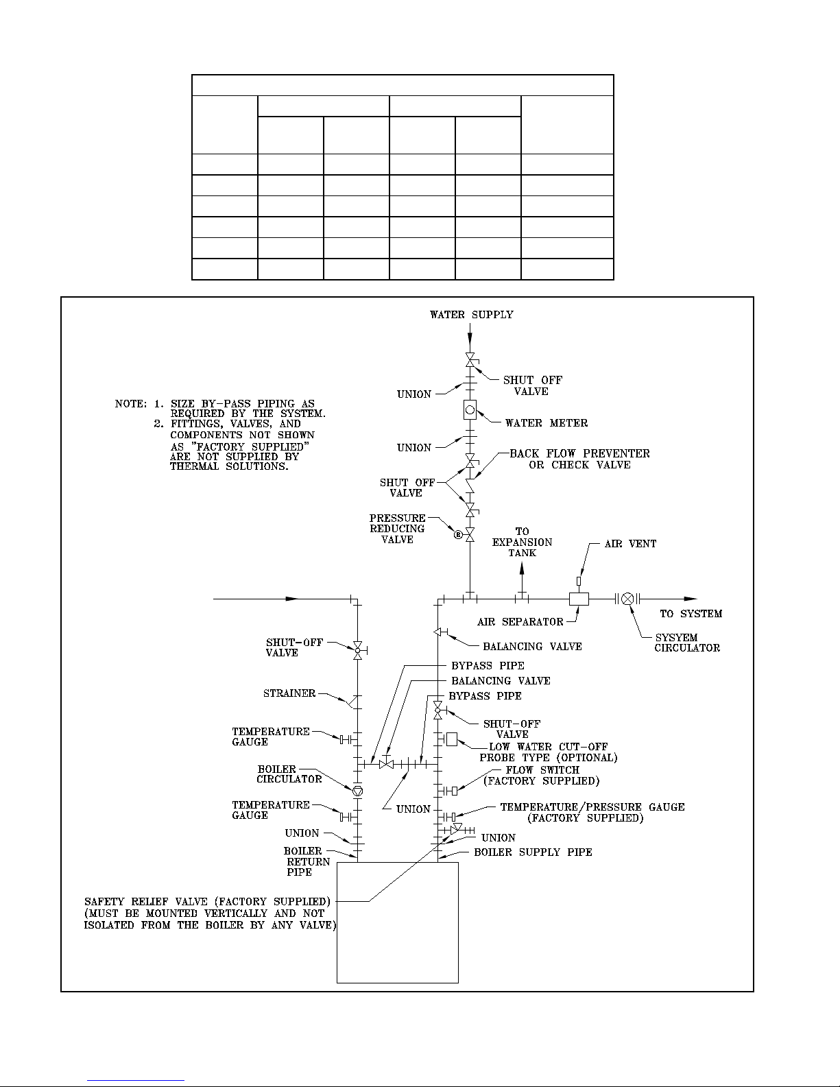
Table 2 - Solaris Boiler Flow and Pressure Drop
20° ΔT (max) 40° ΔT (min)
Boiler
Model
SOL-300 0.8 24 0.5 12 2
SOL-500 6.9 41 1.4 20 2
SOL-750 6.5 64 1.5 32 3
SOL-1000 16.1 85 3.7 43 3
SOL-1250 23.5 106 6.9 53 3
SOL-1500 29.1 128 10.6 64 3
Flow
(GPM) Δ P (ft)
Flow
(GPM)
Supply/Return
Pipe (in. dia.)Δ P (ft)
Figure 12: Water Piping (Single Boiler)
22
Page 23
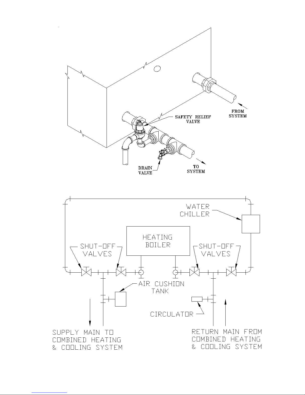
Figure 13: Safety & Drain Valve Installation
Figure 13 A: Recommended Piping for Combination
Heating & Cooling (Refrigeration) System
23
Page 24

V. Gas Piping
WARNING
Failure to properly pipe gas supply to boiler
may result in improper operation and damage to the boiler or structure. Always assure
gas piping is absolutely leak free and of the
proper size and type for the connected load.
An additional gas pressure regulator may
be needed. Consult gas supplier.
A. Size gas piping. Design system to provide adequate gas
supply to boiler. Consider these factors:
1. Allowable pressure drop from point of delivery to
boiler. Maximum allowable system pressure is ½
psig. Actual point of delivery pressure may be less;
contact gas supplier for additional information. The
minimum and maximum gas valve inlet pressure is
stamped on the rating label and can be found in table
3.
2. Maximum gas demand. Refer to the boiler’s input
found in Figure 1 or as printed on it’s rating label.
Also consider existing and expected future gas
utilization equipment (i.e. water heater, cooking
equipment).
3. Length of piping and number of ttings. Refer to
Table 5 for maximum capacity of Schedule 40 pipe.
Table 6 lists equivalent pipe length for standard ttings.
Table 3: Gas Ratings
Maximum
Boiler
Model
SOL-300 14 4.5 3.5
SOL-500 14 4.5 1.3
SOL-750 14 4.5 2.3
SOL-1000 14 4.5 1.9
SOL-1250 14 4.5 1.5
SOL-1500 14 4.5 1.3
Gas Pressure
(in. w.c.)
Minimum
Gas Pressure
(in. w.c.)
Manifold
Pressure
(in. w.c.)
4. Specic gravity of gas. Gas piping systems for
gas with a specic gravity of 0.70 or less can be
sized directly from Table 5, unless authority having
jurisdiction species a gravity factor be applied.
For specic gravity greater than 0.70, apply gravity
factor from Table 4. If exact specic gravity is not
shown choose next higher value.
Table 4: Specic Gravity Correction Factors
Specic
Gravity
0.50 1.10 1.10 0.74
0.55 1.04 1.20 0.71
0.60 1.00 1.30 0.68
0.65 0.96 1.40 0.66
0.70 0.93 1.50 0.63
0.75 0.90 1.60 0.61
0.80 0.87 1.70 0.59
0.85 0.84 1.80 0.58
0.90 0.82 1.90 0.56
1.00 0.78 2.00 0.55
For materials or conditions other than those listed above, re-
fer to National Fuel Gas Code, NFPA54/ANSI Z223.1,
or size system using standard engineering methods
acceptable to authority having jurisdiction.
Correction
Factor
Specic
Gravity
Correction
Factor
B. Connect boiler gas valve to gas supply system.
1. Use methods and materials in accordance with local
plumbing codes and requirements of gas supplier. In
absence of such requirements, follow National Fuel
Gas Code, NFPA 54/ANSI Z223.1.
2. Use thread (joint) compounds (pipe dope) resistant
to action of liqueed petroleum gas.
3. Install sediment trap, ground-joint union and manual
shut-off valve upstream of boiler gas control valve
and outside jacket. See Figure 14.
4. All above ground gas piping upstream from manual
shut-off valve must be electrically continuous and
bonded to a grounding electrode. Do not use gas
piping as grounding electrode. Refer to National
Electrical Code, NFPA 70.
USA boilers built for installation at altitudes greater than 2,000 feet above sea level have been
specically oriced to reduce gas input rate 4 percent per 1,000 feet above sea level per the
National Fuel Gas Code, NFPA 54/ANSI Z223.1.
24
C. Pressure test. The boiler and its gas connection must be
NOTICE
Page 25

Table 5: Maximum Capacity of Schedule 40 Pipe in CFH* for Gas Pressures of 0.5 psig or Less
MANUAL
SHUT-OFF
VALVE
GROUND-JOINT
UNION
TEE
CAP
3" MIN.
0.3 inch w.c. Pressure Drop 0.5 inch w.c. Pressure Drop
Length (Feet)
3/4 1 1-1/4 1-1/2 3/4 1 1-1/4 1-1/2
10 273 514 1060 1580 360 678 1390 2090
20 188 353 726 1090 247 466 957 1430
30 151 284 583 873 199 374 768 1150
40 129 243 499 747 170 320 657 985
50 114 215 442 662 151 284 583 873
60 104 195 400 600 137 257 528 791
70 95 179 368 552 126 237 486 728
80 89 167 343 514 117 220 452 677
90 83 157 322 482 110 207 424 635
100 79 148 304 455 104 195 400 600
* 1 CFH of Natural Gas is approximately equal to 1 MBH.
leak tested before placing boiler in operation.
1. Protect boiler gas control valve. For all testing over
DANGER
½ psig, boiler and its individual shutoff valve must
be disconnected from gas supply piping. For testing at ½ psig or less, isolate boiler from gas supply
Do not use matches, candles, open ames
or other ignition source to check for leaks.
piping by closing boiler’s individual manual shutoff
valve.
2. Locate leaks using approved combustible gas detector, soap and water, or similar nonammable solution.
WARNING
Failure to use proper thread compounds
on all gas connectors may result in leaks of
ammable gas.
WARNING
Gas supply to boiler and system must be
absolutely shut off prior to installing or servicing boiler gas piping.
Table 6: Equivalent Lengths of Standard Pipe Fittings & Valves
VALVES FULLY OPEN
Figure 14: Recommended Gas Piping
Pipe Size I.D. Gate Globe Angle Swing 90° Elbow 45° Elbow 90° Tee, Flow 90° Tee, Flow
1/2” 0.622 0.35 18.6 9.3 4.3 1.6 0.78 1.0 3.1
3/4” 0.824 0.44 23.1 11.5 5.3 2.1 0.97 1.4 4.1
1” 1.049 0.56 29.4 14.7 6.8 2.6 1.23 1.8 5.3
1-1/4” 1.380 0.74 38.6 19.3 8.9 3.5 1.60 2.3 6.9
25
Page 26

VI. Electrical
DANGER
Positively assure all electrical connections are unpowered before attempting installation or service of electrical components or connections of the boiler or building. Lock out all electrical boxes
with padlock once power is turned off.
WARNING
Failure to properly wire electrical connections to the boiler may result in serious physical harm.
Electrical power may be from more than one source. Make sure all power is off before attempt-
ing any electrical work.
Each boiler must be protected with a properly sized over-current device.
Never jump out or make inoperative any safety or operating controls.
The wiring diagrams contained in this manual are for reference purposes only. Each boiler is
shipped with a wiring diagram attached to the front door. Refer to this diagram and the wiring
diagram of any controls used with the boiler. Read, understand and follow all wiring instructions
supplied with the controls.
A. General. Install wiring and electrically ground boiler
in accordance with authority having jurisdiction or, in
the absence of such requirements, follow the National
Electrical Code, NFPA 70, and/or CSA C22.1 Electrical
Code.
B. A separate electrical circuit must be run from the main
electrical service with an over-current device/disconnect in the circuit. A service switch is recommended
and may be required by some local jurisdictions. Install
the service switch in the line voltage “Hot” leg of the
power supply. Locate the service switch such that the
boiler can be shut-off without exposing personnel to
danger in the event of an emergency. Connect the main
power supply and ground to the three (3) boiler wires
(black, white and green) located in the junction box at
the back of the boiler jacket.
C. Refer to Figures 15 and 16 for details on the internal
boiler wiring.
D. When installed, the boiler must be electrically bonded
to ground in accordance with the requirements of the
authority having jurisdiction or, in the absence of such
requirements, with the National Electric Code, ANSI/
NFPA70 and/or the Canadian Electrical Code Part 1,
CSA C22.1, Electrical Code.
NOTICE
This boiler is equipped with a high water temperature limit located inside the internal wiring of the
boiler. This limit provides boiler shutdown in the event the boiler water temperature exceeds the
set point of the limit control. Certain Local Codes require an additional water temperature limit. In
addition, certain types of systems may operate at temperatures below the minimum set point of
the limit contained in the boiler.
If this occurs, install an additional water temperature limit (Honeywell L4006 Aquastat) located in
the system piping as shown in the Water Piping and Trim Section of this manual. Wire as indicated in the Electrical Section of this manual.
26
Page 27

SAGE
CONTROLLER
Solaris
Ladder Diagram
LOW WATER
CUTOFF
OPTION
(SEE NOTE 1)
WATER FLOW SWITCH
BURNER ON/OFF SWITCH
HIGH LIMIT AND OPERATING
TEMPERATURE SWITCHES
HIGH AND LOW GAS
PRESSURE SWITCHES
CNO
CNC
CC
CNO
MM 750-
MT-120
IGNITION PILOT
IGNITION XFMR
IGN
.
LEAD
2
1
P
GR
INTERMITTENT
PILOT
GAS VALVE
3
5
COMBUSTION AIR FLOW
SWITCH
CNO
BLOCKED VENT
GN
RD
10
18
17
20
19
22
21
237
K1 K1
26
27
FUSE
G
2
10 28
8
9
11
12
13
14
16
15
7
8
9
11
10
3
2
5
SENSE
MAIN FUEL VALVE
6
SENSE
COMBUSTION AIR
FLOW
SENSE
HIGH LIMIT
SENSE
GAS PRESS SWITCHES
SENSE
WATER FLOW SWITCH
SENSE
BURNER ON/OFF
SWITCH
SENSE
LOW WATER CUTOFF
6
2
2
2
L1
L2
G
TO DISCONNECT (BY
OTHERS). GROUND
UNIT TO TECHNICAL
EARTH GROUND
120V-1PH-60HZ
43
31
32
34
35
33
36
K5
K5
29
37
38
K3
2
40
39
K4
41
4
4
5
3
K3
K5
K2
K3
SENSE
ALARM RELAY K2
K4
K6
51
52
1
2
1
4
1
5
0-10 VDC
TO
135 OHM
(+)
(-)
HONEYWELL Q7800H
FLAME SAFEGUARD SUBBASE
AND
PROGRAMMER CONTROL
RM7897A-1002
CALL FOR
HEAT
LC
CA
42
47
48
49
K2
2
3
3
2
3
50
2
0
30
K6
45
46
3
2
44
Flame
Rod
F
O+
O-
R+
R-
DP
LR
RO
SI
C
OUTSIDE AIR
SENSOR
REMOTE SYSTEM
SENSOR
OUTSIDE AIR
RESET OPTION
SYSTEM
TEMPERATURE
CONTROL OPTION
OUTLET
SENSOR
INLET
SENSOR
RJ45
MULTIPLE BOILER OUTSIDE AIR AND
REMOTE SYSTEM TEMPERATURE
SENSOR SHARING
C
SP
BP
VI
LO
SO
SYSTEM PUMP
COLD AIR DAMPER,
SYSTEM PUMP BACKUP
OR ALARM
BOILER PUMP
SPARE
LOCKOUT INDICATOR
CONTROL RELAY OPTIONS
MIXING VALVE
ACTUATOR
C-
C+
MR
MS
OR
1-9 VDC
24VAC +
24VAC -
2
12
7
5
4
6
8
9
1
11
10
3
K1
CS
AL
PR
C
LC
CH
FUSE
24VAC +
24VAC -
2
3
7
5
4
6
8
9
1
10
OO V
- V+
P-P
+
CA HL GP WF
Pin 6
Pin 1
Pin 7
Pin 1
BC
BO
BI
V+
V-
COMBUSTION BLOWER
SPEED CONTROL
CIRCUIT (0-10VDC)
COMBUSTION BLOWER
120 VAC CIRCUIT
GND TO
CHASSIS
GND TO
CHASSIS
2
1
3
GND TO
CHASSIS
2
1
3
GND TO
CHASSIS
MAIN
GAS VALVE
115V TO 24V
TRANSFORMER
L2
L1
C
C
C
O+
O-
R+
R-
RJ11
SAGE CONTROLLER PEER-TO-PEER
COMMUNICATION
GND TO
CHASSIS
CNC
NC NC
LINE VOLTAGE ALARM
BLOWER MOTOR
AUXILIARY RELAY
AUXILIARY RELAY
MAIN FUEL VALVE(S)
20
HIGH LIMIT OPERATING LIMIT
HIGH LOW
GND TO
CHASSIS
FACTORY WIRING, LINE VOLTAGE
LINE TYPES:
FIELD WIRING, LINE VOLTAGE
FACTORY WIRING, LOW VOLTAGE(SEE NOTE 3)
FACTORY WIRING, SPECIAL IGNITER
FIELD WIRING, LOW VOLTAGE
25
24
CS AL CH C PR
OO WF GP HL
THERMAL FUSE
(SEE NOTE 2)
BOILER
STATUS
12 VDC
0.5A MAX TOTAL
FOR SO, SP, BP,
V1, & LO
REMOTE ON/OFF
(ENABLE/DISABLE)
SPARE INPUT
DOMESTIC HOT
WATER PRIORITY
LOCAL/REMOTE
(REMOVE JUMPER IF USED)
12 VDC
REMOTE CONTROL
REMOTE SETPOINT
OPTIONAL WIRING
CRA1
CRA2
CRA3
CRA4
CRA5
NOTES:
1. IF LOW WATER CUTOFF (LWCO) IS NOT USED, WIRE #P2 10/THERMAL
FUSE MUST BE WIRED FROM TERMINAL TO THE THERMAL FUSE.
2. IF THE HIGH AND LOW GAS PRESSURE SWITCHES ARE NOT USED, A
WIRE MUST BE INSTALLED BETWEEN TERMINAL AND .
3. FACTORY WIRING, LOW VOLTAGE IS 24VAC UNLESS OTHERWISE INDICATED.
10
16
17
GND TO
CHASSIS
Figure 15: Internal Boiler Wiring Ladder Diagram
27
Page 28

E. System Controls and Wiring
E1
W7W6W5W4W3W2W1
250V T5A
SIZE 3AG
W15
W14 W11
W10 W12
W13
W8
W9
K2
K6
K4K3
K5
K1
24V
COIL
CAUTION
HAZARD OF ELECTRIC SHOCK.
MORE THAN ONE DISCONNECT
SWITCH MAY BE REQUIRED TO
DE-ENERGIZE THE DEVICE
FOR SERVICING.
GND
L2 L1
120VAC POWER
SUPPLY
2
3 10
11 12
13
14
15 16
17
18 19 20
21 2
28
2272
2625
24
23
22
2923031323334353637383940414243444546
32323
3
4748492505152
P8
176
12
RJ11
RJ45
BC
BO
BI
CCC
SO
SP
BPVILO
MR
MS
C-
C+
LC
CH
O+
O+
O-
O-
R+
R+
R-
R-
DP
LR
RO
SI
C
C
CPRALCS
WF
P+P-V+V-OO
CA HL GP
HLPR
C
CHWF
GP
AL
CS
CA
LC
OO
G
L2
3456789
10
F
1213141516171819202122
3 5
SWITCH
ON/OFF
BURNER
NO
NC
C
CNO CNC
GAS PRESSURE SWITCH
LOW HIGH
MANUAL
SWITCH
AIR FLOW
COMBUSTION
TRANSFORMER
IGNITION
PILOT
INGITION
FLAME ROD
OR ALARM
SYSTEM PUMP BACKUP
COLD AIR DAMPER,
SYSTEM PUMP
BOILER PUMP
SPARE
LOCKOUT INDICATOR
AUXILIARY EQUIPMENT
AIR SENSOR
OUTSIDE
SYSTEM TEMPERATURE CONTROL OPTION
OUTSIDE AIR RESET OPTION
WATER PRIORITY
DOMESTIC HOT
(ENABLE/DISABLE)
REMOTE ON/OFF
SPARE INPUT
^WE
^WE
^BK
^BK
WE
BNBNBNBNBN
YW
BN
^BK
^WE
WE
BK
GN
WE
BK
WE
BK
YW
OE
OE
BN
WE
BN
WE
BN
WE
BE
YWYWYWYWYWYWYWYWYW
YW
NC C
NC C
RESET HIGH LIMIT
AUTO
TRANSFORMER
NEC
LOAD
R
C
YW
YW
YW
YW
YW
YW
YW
YW
YW
YW
YW
BE
YW
BE
YW
YW
BE
BE
YW
YW
YW
^WE
^BK
YW
YW
YW
YW
IGN LEAD
SWITCH OPTION
LOCAL REMOTE
(SEE NOTE 3)
BLOCKED
VENT
SWITCH
P1 P2
P3
P5
P4
P6
P7
104 GN
YW
OE
SWITCH
FLOW
WATER
LOW
F1
F2
125V T5A
SIZE 5MM X 20MM
CHASSIS
GND TO
GROUND
L2
L1
TO DISCONECT,
(BY OTHERS)
GROUND UNIT TO
TECHINCAL EARTH GND.
208/230/460V-3PH-60HZ
GN
WE
BK
CHASSIS
GND TO
OE
2
1
3
CHASSIS
GND TO
2
1
3
CHASSIS
GND TO
GAS VALVE
IGNITION PILOT
GAS VALVE
MAIN
WIRE COLORS:
BE = BLUE
BK = BLACK
BN = BROWN
GN = GREEN
OE = ORANGE
PK = PINK
RD = RED
VT = VIOLET
WT = WHITE
YW = YELLOW
RELAY/SWITCH TERMINALS:
C = COMMON
NC = NORM. CLOSED
NO = NORM. OPEN
WIRE TYPES:
(BLACK COLOR SHOWN, TYPICAL FOR ALL COLORS)
FACTORY WIRING, LINE VOLTAGE, 12 AWG, 105°C
FACTORY WIRING, LINE VOLTAGE, 18 AWG, 105°C
FACTORY WIRING, LOW VOLTAGE, 18 AWG, 105°C
FACTORY WIRING, LOW VOLTAGE, 18 AWG, SHIELDED
FACTORY WIRING, SPECIAL IGNITER, NOT IN HARNESS
OPTIONAL WIRING, LINE VOLTAGE, NOT IN HARNESS, 18AWG, 105°C
OPTIONAL WIRING, LOW VOLTAGE, NOT IN HARNESS
^BK
BK
BK
*BK
WE
BK
CHASSIS
GND TO
BLOWER
VARIABLE SPEED
PIN 6
PIN 1
PIN 7
PIN 1
BK
WE
(SEE NOTE 2)
(CRA1)
(CRA2)
(CRA3)
(CRA4)
(CRA5)
STANDARD FACTORY WIRING, LINE VOLTAGE, NOT IN HARNESS, 18AWG, 105°C
STANDARD FACTORY WIRING, LOW VOLTAGE, NOT IN HARNESS
STANDARD FACTORY WIRING, NOT IN HARNESS, 16AWG, 200°C
FUSE
^BK
^WE
NO
C
C
NC
THERMAL FUSE
(SEE NOTE 1)
(INSTALL IGNITION TERMINAL,
RAJAH MODEL AEBF)
(REMOVE)
(REMOVE)
(REMOVE)
(REMOVE)
(REMOVE)
(REMOVE JUMPERS 11, 12, & 15)
NOTES:
1. IF THE LOW WATER CUTOF F(LWCO) IS USED, DISCONNECT WIRE LABELED
P2 10/THERMAL FUSE FROM THE THERMAL FUSE AND CONNECT IT TO
LWCO TERMINAL 3. ALSO, CONNECT LWCO TERMINAL 5 TO THE THERMAL FUSE.
2. IF GAS PRESSURE SWITCHS ARE USED, INSTALL WIRING BETWEEN P16 AND
P17 TO INCLUDE THE PRESSURE SWITCH(S) AS SHOWN. IF NO GAS PRESSURE
SWITCH IS REQUIRED, INSTALL A JUMPER BETWEEN TERMINALS P16 AND
P17 AS SHOWN.
3. IF THE REMOTE ON/OFF FUNCTION IS DESIRED, REMOVE JUMPER WIRE BETWEEN
TERMINALS RO & C AND WIRE AS SHOWN. NOT TO BE DONE AT FACTORY.
THERMAL SOLUTIONS SAGE CONTROLLER™ (SBC™)
PART NO. 801SOL0001
(BACK VIEW)
P12
LOW WATER
CUTOFF (LWCO)
OPTION
WE
GN
HONEYWELL
PROGRAMMER CONTROL
RM789A-1002
HONEYWELL Q7800H
PART NO. 101182-01
CHASSIS
GND TO
1. Refer to National Electric Code or Local Electric Codes for proper size and type of wire required. Follow Code.
2. Use anti-short bushings on all wiring passing through boiler jacket, junction boxes and/or control boxes.
3. Use armored cable (BX) over all exposed line voltage wiring.
28
Figure 16: Schematic Diagram
Page 29

VII. Modular Installation
A. General Guidelines
1. Read and follow all venting, combustion air, water
piping, gas piping and electrical instructions contained in this manual unless otherwise instructed in
this section.
2. Consult Local Building Codes or National Fuel Gas
Code, NFPA 54/ANSI Z222.3 for restrictions and
instructions on modular boiler installations.
3. Modular systems are complex. Design and installation of modular systems should only be undertaken
by skilled and knowledgable engineers and contractors.
4. Use stainless steel vent material approved for con-
densing ue gass applications.
B. Module Sizing
Thermal Solutions recommends sizing each boiler in a
modular system to provide 20 % of the combined heating load where ever possible. If the combined load ex-
ceeds the output of ve (5) boilers, install the minimum
number of boilers to meet the load requirements.
C. Venting
1. Horizontal/Vertical Venting
a. Use Stainless Steel vent material approved for
condensing ue gas applications.
WARNING
CAUTION
Installing multiple vent terminations close
together promotes frost buildup on buildings. To minimize this possibility, extend the
distance from the building to the end of the
vent termination and increase the horizontal
distance between terminations.
f. Refer to the cautions, notices, and warnings in
Section III.
2. Conventional Venting (Negative Draft)
a. Refer to Figure 17 for conventional venting
guideline for modular boilers.
b. Refer to National Fuel Gas Code to determine
required chimney diameter and common venting diameter. Note that combined input, lateral
length and chimney height affect vent diameter.
c. A single double acting barometric damper can
be utilized on the common venting when venting
according to Figure 17.
d. Slope common venting a minimum of one (1)
inch in four feet of run towards boilers.
e. Locate boiler(s) with lowest input closest to
chimney.
f. Refer to cautions, notices, and warnding in Sec-
tion III.
Do not manifold vent components of a
boiler without correcting to negative draft.
b. See Table 1 for the maximum vent length of each
size boiler.
c. Refer to Section III of this manual for guidelines
on venting of modular boilers individually. Each
boiler requires an individual vent pipe.
d. The minimum horizontal distance between vent
terminations is one (1) foot. Additional horizontal distance is desirable to avoid frost damage to
the building. Vent terminations must be at least
twelve (12) inches above the ground plus the
expected snow accumulation.
e. Multiple vertical vent pipes may be piped
through a common conduit or chase so that one
roof penetration may be made. Each vent termination must be one (1) foot from other terminations. A minimum of at least six (6) inches from
the common conduit to combustible material
must be maintained unless otherwise instructed
by the conduit manufacturer.
D. Air Intake Piping
1. Locate air intake termination on the same wall as
the vent termination if possible, to prevent nuisance
boiler shutdowns. However, boiler may be installed
with vertical venting and sidewall combustion air
inlet (or visa versa) if installation conditions do not
allow alternate arrangement.
2. Refer to Figures 18 and 19 for common air intake
guidelines for modular water heaters.
3. Individual air intake pipes may be used in lieu of
common air intake piping. If so desired, refer to
Figures 4 and 8.
4. Refer to Table 1 for the maximum air intake length.
Common air intake straight lengths and ttings
should be assumed to have the equivalent length
the same as an individual air intake pipe used for a
given boiler intake pipe diameter.
5. Position horizontal air intake termination center line
below horizontal vent termination’s center line.
6. Vertical air intake pipe must terminate at least two
(2) feet above teh closest portion of the roof.
7. Refer to the cautions, notices, and warnings in the
Combustion Air Section of this manual.
29
Page 30

E. Water Piping
1. Refer to Figures 20 through 25 for typical water pip
ing installation details for modular boilers.
2. Installing a low water cutoff in the system is highly
recomended and may be required by code.
3. Refer to Table 2 for pressure drop and ow requirements for each boiler.
4. Refer to the instructions, cautions, notices, and
warnings in Section IV.
F. Gas Piping
1. Refer to National Fuel Gas Code, Local Codes and
Tables 5 and 6 for gas pipe sizing.
2. Each boiler must be piped as shown in Figure 14.
3. Refer to the instructions, catuions, notices, and
warnings in Section V.
G. Electrical
WARNING
If gas pressure in the building is above 1/2
psig, an additional gas pressure regulator is
required. Using one additional regulator for
multiple boilers may result in unsafe boiler
operation. The additional regulator must be
able to properly regulate gas pressure at
the input of the smallest boiler. If the regulator cannot do this, two or more additional
regulators are required. Consult regulator
manufacturer and/or local gas supplier for
instructions and equipment ratings.
-
1. Each boiler must be provided with a fused discon
nect and service switch.
2. Install wiring in accordance with requirements of
authority having jurisdiction. In the absence of such
requirements, follow the National Electric Code,
NFPA 70 and/or CSA C22.1 Electric Code.
3. Refer to Figure 2 for electrical data for each boiler
size.
4. Refer to the instructions, cautions, notices, and
warnings found in Section VI.
30
-
Page 31

Figure 17: Modular Boiler Conventional Venting
Figure 18: Modular Boiler Horizontal Air Intake Piping
31
Page 32

LISTED IN TABLE 1.
Figure 19: Modular Boiler Vertical Air Intake Piping
32
Page 33

Figure 20: Modular System: Typical One Pipe Water Piping
33
Page 34

34
Figure 21: Modular System: Typical Primary/Secondary Water Piping
Page 35

Figure 22: Modular System: Typical Primary/Secondary without System Pump
35
Page 36

36
Figure 23: Modular System: Typical Reverse - Return Water Piping
Page 37

Figure 24: Modular System Reverse - Return with System Pump Only
37
Page 38

38
Figure 25: Modular System: Typ Primary/Secondary with Reverse-Return
Page 39

VIII. System Start-up
A. Safe operation and other performance criteria were met
with gas manifold and control assembly provided on
boiler when boiler underwent tests specied in American National Standard for Gas-Fired Low-Pressure
Steam and Hot Water Boilers, ANSI Z21.13.
B. Verify that the venting, water piping, gas piping and
electrical system are installed properly. Refer to installation instructions contained in this manual.
C. Conrm all electrical, water and gas supplies are turned
off at the source and that vent is clear of obstructions.
D. Conrm that all manual shut-off gas valves between the
boiler and gas source are closed.
WARNING
Completely read, understand and follow all
instructions in this manual before attempting start up.
E. FILL ENTIRE HEATING SYSTEM WITH WATER
and vent air from system. Use the following procedure
on a Series Loop or multi-zoned system installed to
remove air from the system while lling.
WARNING
3. Attach a hose to the vertical hose bib located prior to
the full port ball valve in the system supply piping.
(Note - Terminate hose in ve gallon bucket at a
suitable oor drain or outdoor area).
4. Starting with one circuit at a time, open zone valve
or shut-off valve in system supply and return piping.
5. Open hose bib.
6. Open ll valve (Make-up water line should be located directly after full port ball valve in system supply
piping between air scoop and expansion tank).
7. Allow water to overow from bucket until discharge
from hose is bubble free for 30 seconds.
8. Close the opened zone valve or shut-off valve for
the zone being purged of air, then open the zone
valve or shut-off valve for the next zone to be
purged. Repeat this step until all zones have been
purged. At completion, open all zone valves or
shut-off valves.
9. Close hose bib, continue lling the system until the
pressure gauge indicates required system operating
pressure. Close ll valve.
(Note - If make-up water line is equipped with
pressure reducing valve, system will automatically
ll to set pressure. Follow ll valve manufacturer’s
instructions).
10. Open isolation valve in boiler supply piping.
The maximum operating pressure of this
boiler is 150 psig. Never exceed this pressure. Do not plug or change pressure relief
valve.
NOTICE
If it is required to perform a long term pressure test of the hydronic system, the boiler
should rst be isolated to avoid a pressure
loss due to the escape of air trapped in the
boiler.
To perform a long term pressure test includ-
ing the boiler, ALL trapped air must rst be
removed from the boiler.
A loss of pressure during such a test, with
no viable water leakage, is an indication
that the boiler contained trapped air.
1. Close full port ball valve in boiler supply piping.
2. Isolate all zones by closing zone valves or shut-off
valves in supply and return of each zone(s).
11. Remove hose from hose bib.
F. Conrm that the water ow switch is operating prop-
erly.
G. Turn on the electrical supply to the boiler and circula-
tion system at the fused disconnect.
H. Conrm that water ow switch is operating properly.
I. Prepare to check operation.
1. Obtain the gas heating value (in Btu per cubic feet)
from the gas supplier.
2. Connect a monometer to the pressure taping
upstream V1 on the main gas valve. Use the G 1/8
test nipple provided. Reference item 7 on gure 28.
3. Temporarily turn off all other gas-red appliances.
4. Turn on gas supply to the boiler gas piping.
5. Purge the gas line of air.
6. Reset the low gas pressure switch.
7. Conrm that the supply pressure to the gas valve is
14 in. w.c. or less. Refer to Table 3 for the minimum
supply pressure.
39
Page 40

DANGER
Do not use matches, candles, open ames
or other ignition source to check for leaks.
8. Open the eld installed manual gas shut-off valve
located upstream of the gas valve on the boiler.
9. Check that boiler gas piping, valves, and all other
components are leak free using a soap solution or
a similar non-combustible solution, electronic leak
detector or other approved method. Eliminate any
leaks.
J. Follow the operating instructions to place the boiler
into operation. Reference Figure 27.
K. Sequence of operation. See Figure 29. If boiler fails to
operate properly, see Trouble shooting Guide in Section
IX.
L. Select Desired Operating Mode. Refer to the Sage
Boiler Control ™ (SBC ™) instructional manual supplied with the boiler.
M. Set operating limits. Refer to the (SBC ™) instructional
manual supplied with the boiler.
Figure 26: Pilot Burner/Main Burner Flame
N. Check Ignition control module shut-off.
1. Rotate the manual gas shut-off valves clockwise
from “ON” to “OFF” position.
2. Turn on the boiler-operating switch located on the
left side of the unit.
3. Allow boiler to complete prepurge and pilot trial for
ignition (PTIF) sequence. Conrm that the ame
control locks out on pilot ame failure.
4. Rotate the manual shut off valve for the pilot to al-
low gas ow to the pilot valve.
5. Allow the boiler to complete the pre-purge, PTIF,
and main trial for ignition (MTFI). Conrm that the
ame control locks out on main ame failure.
6. Rotate the manual shut off valves for the main gas
valve to allow gas ow to the main gas valve. Conrm that the ame control locks out on main ame
failure.
7. Disconnect the pilot lead wires from the pilot gas
valve. If the burners do not shutdown, determine the
cause of the malfunction. Replace necessary items
and check operation.
40
Page 41

FOR YOUR SAFETY READ BEFORE OPERATING
WARNING:
A.
This appliance is equipped with an ignition device, which
automatically lights the pilot. Do not try to light the pilot by
hand.
B.
BEFORE OPERATING smell all around the appliance area
forgas.Besuretosmellnexttotheoorbecausesomegasis
heavierthanairandwillsettleontheoor.
WHAT TO DO IF YOU SMELL GAS
• Do not try to light any appliance.
• Do not touch any electric switch; do not use any phone in
your building.
• Immediately call your gas supplier from a neighbor’s
phone. Follow the gas supplier’s instructions.
Ifyoudonotfollowtheseinstructionsexactly,areorexplosionmayresult
causing property damage, personal injury, or loss of life.
OPERATING INSTRUCTIONS
1.
STOP! Read the safety information above on this label.
2.
Set the thermostat to lowest setting.
3.
Turn off all electric power to the appliance.
4.
This appliance is equipped with an ignition device, which
automatically lights the pilot. Do not try to light the pilot
by hand.
Inlet Gas
5.
Remove front door.
•Ifyoucannotreachyourgassupplier,calltheredepartment.
C.
Use only your hand to push in or turn the gas control knob.
Never use tools. If the knob will not push in or turn by hand,
don’ttrytorepairit,callaqualiedservicetechnician.
Forceorattemptedrepairmayresultinareorexplosion.
D.
Do not use this appliance if any part has been under water.
Immediatelycallaqualiedservicetechniciantoinspectthe
appliance and to replace any part of the control system and
any gas control which has been under water.
7.
Rotate gas shutoff valves clockwise from “ON” position
to “OFF”. Make sure handle rests against stop.
8.
Waitve(5)minutestoclearoutanygas.Thensmellfor
gas,includingneartheoor.Ifyousmellgas,STOP!Follow
“B” in the safety information above on this label. If you do
not smell gas, go to the next step.
9.
Rotate gas shutoff valves counterclockwise from
“OFF” to “ON”. Make sure handle rest against stop. Do not
force.
6.
Locate the gas pilot & main
shutoff valves at the end
of the gas supply pipe
inside the boiler.
Gas Shut Off Valves
TO TURN OFF GAS TO APPLIANCE
1.
Set the thermostat to lowest setting.
2.
Turn off all electric power to the appliance if service is to be
performed.
3.
Remove front door.
Figure 27: Operating Instructions
10.
Replace front door.
11.
Turn on all electric power to the appliance.
12.
Set thermostat to desired setting.
13.
If the appliance will not operate, follow the instructions “TO
TURN OFF GAS TO APPLIANCE” and call your service
technician or gas supplier.
4.
Rotate gas shutoff valves clockwise from “ON” position
to “OFF”. Make sure handle rests against stop.
5.
Replace front door.
814SOL0001
41
Page 42

1 Electrical connection for valves (DIN EN 175 301-803) 10 Setting screw Ratio V
2 Input ange 11 Vent nozzle G 1/8
3 Pressure connection G 1/8 upstream of lter 12 G 1/8 pressure connection Burner pressure p
4 Filter 13 Output ange
Test point connection G 1/8 upstream of V1, possible
5 Type plate 14
both sides
6 Cover 15 G 1/8 pressure connection blower pressure p
Test point connection G 1/8 upstream of V1, possible
7
on both sides 16 G 1/8 pressure connection for pF furnace pressure
Test point connection G 1/8 downstream of V2
8
possible on both sides 17 Optional: Pulse line pBr
9 Setting screw Zero point adjustment N * G 1/8: 1/8” Iso Parallel Threads
Figure 28: Main Gas Valve
Br
L
42
Page 43

Figure 29: Sequence of Operation
43
Page 44

O.Checkthepilotandmainburnerames.Allow the
boiler to complete pre-purge, PTIF, and MTFI. Look
through the boiler sight glass and check the pilot and
main burner ames. Reference Figure 26 for ame appearance. The ames should have a clearly dened in-
ner cone with no yellow tipping. Orange-yellow streaks
should not be confused with true yellow tipping. If the
ames do not meet the criteria in gure 26, adjust the
gas valve settings as described in step R.
WARNING
c. Use the N setting (Item 9 on Figure 28) on the
main gas valve to adjust the gas manifold pres-
sure at low re. Turn the screw setting clockwise
to increase counterclockwise to decrease the
manifold pressure.
3. Clock the gas meter for at least 30 seconds. Use
table 7 to determine the gas ow rate in cubic feet
per hour.
4. Determine the input rate. Multiply the gas ow rate
by the gas heating value.
Failure to properly adjust gas input rate will
result in over ring or under ring of the appliance. Improper and unsafe boiler operation may result.
P. Check low water cut-off (if so equipped).
1. Adjust setpoint to highest setting.
2. With boiler operating, open the drain
valve and slowly drain the boiler.
3. Main burners and pilot burner will extinguish and
blower will stop when the water level drops below
the low water cutoff probe. Verify limit, thermostat
or other controls have not shut off the boiler.
4. Adjust the setpoint to the desired value and rell
the boiler.
Q. Verify that all safety and operating limits are operat-
ing properly. These controls and limits include differ-
ential air switch, water temperature operating control,
manual reset water temperature safety limit, and the
high and low gas pressure switches (if provided). Refer
to the individual manuals, provided with the boiler, for
these components to obtain proper start-up and operating instructions. Follow all instructions contained in
these manuals. Refer to section IX to view a description
of the safety and operating controls.
R. Adjust the gas input rate to the boiler.
1. Administer a call for heat and allow the boiler to
operate.
2. Check the manifold pressure at high re and low
re. See table 3 or the rating label located in the
boiler’s vestibule compartment.
a. Connect manometer to pressure tapping
downstream V1 on main gas valve. See item 8 on
Figure 28.
b. Use the V setting (Item 10 on Figure 28) on
the main gas valve to adjust the gas manifold
pressure at high re. Turn the screw setting
clockwise to increase and counterclockwise to
decrease the manifold pressure.
WARNING
Failure to properly adjust gas input will
result in over ring or under ring of the
appliance. Improper and unsafe operation
may result.
5. Compare the measured input rate to the input rate
stated on the rating plate.
a. The boiler must not be over red. Reduce the
input rate by decreasing the manifold pressure as
described in step R. Do not reduce more than 0.3
inch w.c. If the boiler is still over red, contact
your Thermal Solutions representative.
b. If the measured value is less than 98% of the
rating plate input, increase the input rate by
increasing the manifold gas pressure described
in step R. Do not increase the manifold pressure
more than 0.3 inch w.c. Contact your Thermal
Solutions representative if the measured rate is
still less than 98% of the rated input.
WARNING
Failure to properly adjust excess air will
result in unsafe levels of carbon monoxide.
Variations in venting or combustion air pressure and temperature will change excess
air. Adjust excess air levels so that variation
in venting or combustion air pressures and
temperatures caused by change of seasons, wind conditions, opening or closing of
boiler room doors or windows do not cause
the boiler to operate with carbon monoxide
concentrations above 400 parts per million.
6. Measure the percent oxygen (%O2), the carbon
monoxide concentrations in the ue gas (CO ppm),
and the ue gas temperature. Compare the results
44
Page 45

with the values given on the factory re test report
supplied with the boiler.
7. Return gas red appliances to previous conditions of
use.
S. Review user’s information manual and system Op-
eration with owner or operator.
Table 7: Gas Flow Rate in Cubic Feet Per Hour
Size of Gas Meter Dial
Seconds
for One
30 60 120 240
32 56 113 225
34 53 106 212
36 50 100 200
38 47 95 189
40 45 90 180
42 43 86 172
44 41 82 164
46 39 78 157
48 37 75 150
50 36 72 144
52 35 69 138
54 33 67 133
56 32 64 129
58 31 62 124
60 30 60 120
One-Half
Cu. Ft.
One
Cu. Ft. Two Cu. Ft.
45
Page 46

IX. Service and Maintenance
DANGER
This boiler uses ammable gas, high voltage electricity, moving parts, and very hot water under
high pressure. Assure that all gas and electric power supplies are off and that the water temperature is cool before attempting any disassembly or service.
Do not attempt any service work if gas is present in the air in the vicinity of the boiler. Never
modify, remove or tamper with any control device.
WARNING
This boiler must only be serviced and repaired by skilled and experienced service technicians.
If any controls are replaced, they must be replaced with identical models.
Read, understand and follow all the instructions and warnings contained in all the sections of this
manual.
If any electrical wires are disconnected during service, clearly label the wires and assure that the
wires are reconnected properly.
Never jump out or bypass any safety or operating control or component of this boiler.
Read, understand and follow all the instructions and warnings contained in ALL of the compo-
nent instruction manuals.
Assure that all safety and operating controls and components are operating properly before plac-
ing the boiler back in service.
CAUTION
Label all wires prior to disconnection when servicing controls. Wiring errors can cause improper
and dangerous operation.
Verify proper operation after servicing.
ATTENTION
Au moment de l’entretien des commandes, étiqueteztous les ls avant de les débrancher. Des
erreurs de câblage peuvent entraîner un fonetionnement inadéquat et dangereux.
S’assurer que l’appariel fonctionne adéquatement une fois l’entretien terminé.
A. Periodic Maintenance. Inspection and service should
be conducted periodically. Turn off electrical power and
gas supply while conducting service or maintenance.
Follow instructions TO TURN OFF GAS TO APPLIANCE. See Figure 27.
1. General
a. Keep the area around the boiler free from com-
bustible materials, gasoline and other ammable
vapors and liquids.
b. Keep the area around the combustion air inlet
terminal free from contaminates.
c. Keep the boiler room ventilation openings open
and unobstructed.
2. Low water cutoff (if so equipped).
a. Probe Type (Annual Service). Probe type
LWCO should be removed once a year, examined and cleaned of any dirt accumulations to assure proper operations. Do not attempt to repair
mechanisms in the eld. Complete replacement
mechanisms, including necessary gaskets and
installation instructions, are available from the
manufacturer.
3. Vent/Air Intake System. Inspect for obstructions,
soot accumulation, proper support, deterioration of
46
Page 47

pipe, ttings, and joints.
a. Clean terminal screens. Terminals must be free
of obstruction, undamaged, with screens securely
in place.
b. Inspect and clean the air lter as needed. The
lter can be cleaned using water. See Figure 39,
Item 11, for location.
c. Terminal Wall thimbles (if used) must be weath-
ertight.
d. Pipe must be full round shape, and show no dam-
age from impact or excessive temperature.
e. Ensure that there is nothing obstructing the ow
of combustion air and/or ue gas.
f. Inspect and clean piping with soft bristle brush
and vacuum to remove any lint, soot, or other
dirt.
g. Replace immediately if any signs of deterioration
or corrosion are present.
h. Pipe must be supported at minimum ve (5) foot
intervals and must not sag.
i. All vent joints must be secure and watertight.
j. All air intake joints must be secure and airtight.
k. Horizontal vent tee drain or vertical vent tee
drain (if used) must have minimum 6 inch trap
and allow condensate to ow freely. To Clean:
i. Disconnect drain tube from drain tting.
ii. Flush drain tube with water. Fill trap with
water.
iii. Securely fasten drain tube to drain tting,
providing gas-tight and watertight seal.
1/2 inch of sensing probe. If ame is yellow and
lazy, follow instructions TO TURN OFF GAS
TO APPLIANCE (see Figure 27), and contact
qualied agency.
e. Check main burner ames. See Figure 26. Flame
should have clearly dened inner cone with no
yellow tipping. Orange-yellow streaks caused
by dust should not be confused with true yellow
tipping. If yellow ames are observed, follow
instructions TO TURN OFF GAS TO APPLI-
ANCE (see Figure 27), and contact qualied
service agency.
6. Combustion Chamber/Burners . Inspect for
blockage or soot accumulation (annually).
a. Remove Main Burners. See Figure 30.
1. Remove front door.
2. Remove air box cover.
3. Disconnect ignition wire, sensor wire,
ground wire and gas valve wiring.
4. Disconnect manifold unions at pilot valve
and main gas inlet on right side of air box.
5. Remove attachment screws holding air box
to front of combustion chamber.
6. Remove burner/fuel train assembly from
combustion chamber.
7. Inspect and clean burners with soft bristle
brush and vacuum to remove any dirt and
lint.
l. If pipe must be disassembled for removal of
obstructions or resealing of joint, see Section III,
Paragraph B.
4. Inspect Condensate Drain Trap and
Drain Line (Monthly)
a. Inspect condensate trap water level. If low, add
water to bring level to trap discharge.
b. Ensure condensate can ow freely to drain.
5. Inspect Pilot and Main Burner Flames
(Monthly).
a. Remove jacket front panel.
b. View ames through Flame Observation Port.
c. Adjust thermostat to highest setting.
d. Check pilot ame. See Figure 26. The pilot pro-
duces three (3) ames. The center ame should
be steady, medium hard blue enveloping 3/8 to
8. If burners show signs of deterioration or corrosion, replace immediately.
9. Check gas orices for dirt and lint. Clean as
necessary.
10. Inspect heat exchanger and combustion
chamber. Clean heat exchanger with
straight handle wire brush and vacuum heat
exchanger and combustion chamber.
1. Exercise care during vacuuming to
avoid damaging base insulation.
11. Inspect combustion chamber/burner assembly gaskets and replace if required.
12. Install burner/fuel train assembly and secure
with original fasteners.
13. Connect manifold unions, ignition wire, sen-
47
Page 48

sor wire, ground wire and gas valve wiring.
WIRE BRUSH
SOFT BRISTLE BRUSH
14. Install air box cover and attachment hardware.
15. Install front door.
6. Check Operation . Follow steps from Section VIII
for system start-up.
Figure 30: Cleaning Boiler Flue Passages
48
Page 49

B. Safety and Operating Controls. Operation and Shut Down
Component Function
Circuit Board Fuse
Power Switch
Operating Aquastat
Manual Reset High
Limit Aquastat
Flow Switch
Pressure (Safety)
Relief Valve
Mixer Fuseable Link
If the power draw of the control circuit exceeds approximately 5 amps, the circuit board
fuse trips and prevents the boiler from operating until the fuse is replaced.
If this switch is in the off position, power is interrupted to the control circuit of the boiler,
which prevents the boiler from operating. If the switch is in the on position, power is supplied to the control circuit.
If the boiler water temperature exceeds the adjustable set point, power is interrupted to the
control circuit of the boiler, which prevents the boiler from operating. When the boiler water temperature drops below the set point minus the adjustable differential setting, power is
again supplied to the control circuit.
If the boiler water temperature exceeds the adjustable set point, power is interrupted to the
control circuit of the boiler, which prevents the boiler from operating. Power is interrupted
until the control is manually reset by pressing the control’s reset button. When the button
is depressed, power will again be supplied to the control circuit.
If the water ow through the boiler drops below the xed ow rate required to move the
control’s paddle enough to close the controls contacts, power is interrupted to the control
circuit, which prevents the boiler from operating. When the water ow rate is increased,
the paddle closes the control’s contacts and power is supplied to the control circuit.
If the pressure inside the appliance exceeds the xed set point, the valve opens mechanically and discharges water. The valve remains open until the pressure inside the appliance
drops below the set point.
If the temperature in the interior of the burner exceeds the xed set point. The contacts of
the switch open and power is interrupted to the control circuit, which prevents the boiler
from operating. Power is interrupted until the switch is replaced.
Vestibule Fuseable
Link
High and Low Gas
Pressure Switches
Combustion Air Flow
Switch
Flame Safeguard
Control
Variable Frequency
Drive (VFD)
Thermal Solutions
Sage Boiler Control™
(SBC)™
If the temperature in the interior of the vestibule enclosure exceeds the xed set point, the
contacts of the switch open and power is interrupted to the control circuit, which prevents
the boiler from operating. Power is interrupted until the switch is replaced.
If the gas pressure reaches a point below the adjustable set point, or above the adjustable
set point, the contacts of the switch open and power is interrupted to the control circuit,
which prevents the boiler from operating. Power is interrupted until gas pressure is between the high and low set points and the control is manually reset by moving the switch to
the reset position. The switches will not reset until the gas pressure is within the set point
parameters.
If the differential air pressure drops below the xed set point, the contacts of the switch
open and power is interrupted to the control circuit, which prevents the boiler from operat-
ing. Power is interrupted until air ow increases so that the contacts close.
Refer to the manual supplied with the boiler.
The variable frequency drive’s primary function is to vary the rotational speed of the blower
fan based on the air requirements of the boiler combustion process. The VFD on Modulat-
ing boilers responds to a 0-10 VDC or 4-20 ma signal from the Digital Temperature Controller.
The Thermal Solutions Sage Boiler Control™ (SBC™) is a complete boiler and automation system. It provides advanced boiler modulation control, operating control, diagnostics,
multiple boiler lead lag and auxiliary device control. Refer to the SBC manual shipped with
the boiler to learn more about these features and functions.
49
Page 50

C. Trouble Shooting Guide
Alarm Messages are shown one at a time in priority order. The message closes to the top of this list is displayed rst. Following
messages are not show until the higher priority message has cleared. All alarm messages are also stored in the fault history.
LCD Display
Alarm Message
Low Water Level
Off Switch Turn Burner Switch On
Low Water Flow
Fuel Limit
High Temp Limit
Low Air Flow
FSG Fault
Outlet Temp Fail
Inlet Temp Fail
OA Temp Fail
Remote Temp Fail
Recommended
Action
Manually Reset the Low
Water Cutoff
Ensure Boiler Pump is
Running and Boiler
Water Flow is
Unobstructed
Manually Reset the Fuel
Pressure Switch
Manually Reset the
High Temperature
Aquastat
Check Combustion Air
Blower and Air
Pressure Switch
Settings and Wiring
Manually Reset
Required, Refer to
Flame Safeguard
Manual
Corrective Actions
Check Wiring and
Sensor
Check Wiring and
Sensor
Check Wiring and
Sensor
Check Wiring and
Sensor
Explanation
Low Water Cutoff Switch
When this option is congured and an instrument is installed, the manual reset
low water safety relay is preventing the boiler from starting. If terminal (LC) does
not receive power and the Call For Heat output (CH) is powered the “Low Water
Level” Message is displayed.
Burner Switch is Off
Control switch is in the OFF position and is preventing the boiler from starting. If
terminal (OO) does not receive power and the Call For Heat output (CH) is powered the “OFF Switch” Message is displayed.
Low Water Flow Switch
Low water ow is preventing the boiler from starting. If terminal (WF) does not
receive power and the Call For Heat output (CH) is powered the “Low Water
Flow” Message is displayed.
Low or High Gas Pressure Switch
The low or high gas pressure switch is preventing the boiler from starting. If
terminal (GP) does not receive power and the Call For Heat output (CH) is
powered the “Fuel Limit” Message is displayed.
High Limit Temperature
The high temperature limit (HL) (and operational temperature limit when
provided) aquastat is preventing a boiler start. If terminal (HL) does not receive
power and the Call For Heat output (CH) is powered the “High Temp Limit”
Message is displayed.
Low Air Flow or Blocked Vent Switch Not Made
The air ow (and blocked vent switch when provided) is preventing a boiler start.
If terminal (CA) does not receive power and the Call For Heat output (CH) is
powered the “Low Air Flow” Message is displayed.
Flame Safeguard Fault
The Flame Safeguard is preventing a boiler start. If terminal (AL) receives power
at any time, the “Flame Failure” Message is displayed.
Boiler Outlet Temperature Sensor Fail
The boiler outlet temperature sensor is not connected or is reading above or
below a valid range. When the boiler outlet sensor fails and the Outlet Sensor
mode was selected the control will transfer to Lost Sensor Blind Mode.
Boiler Inlet Temperature Sensor Fail
The boiler inlet temperature sensor is not connected or is reading above or below
a valid range. When the boiler inlet sensor fails the mixing valve output will drive
to 0% and low temperature alarm and maximum water differential (boiler outlet
minus boiler inlet) temperature hold are disabled.
Outside Air Temperature Sensor Fail
The outside air sensor is congured and is not connected or is reading above or
below a valid range. When the outside air sensor fails the warm weather shutdown (WWSD) and outside air reset control logics are disabled.
Remote System Temperature Sensor Fail
The remote system temperature sensor is congured and is not connected or is
reading above or below a valid range. If Remote System Temperature Sensor
mode was selected the control will transfer to Boiler Outlet Sensor Mode.
50
Page 51

Trouble Shooting Guide (continued)
LCD Display
Alarm Message
Remote Input Fail
Comm Failure
Recommended
Action
Check Wiring and
Remote System
Check Wiring and
Remote System
Conrm each boiler has
a unique address
Explanation
Remote Control Input Fail
The Remote Control Input is congured and is not connected or is above or below a valid range. When the remote control input fails the following control mode
changes are taken automatically:
Selected Modes Resulting Control Mode
Remote Mod Outlet Sensor and Local Setpoint
Remote Mod & Remote Sensor Remote Sensor and Local Setpoint
Remote SP Outlet Sensor and Local Setpoint
Remote SP & Remote Sensor Remote Sensor and Local Setpoint
Communication Failure
The Modbus or Peer-To-Peer network has failed. When the Modbus network fails
the following control mode changes are taken automatically:
Selected Modes Resulting Control Mode
Modbus Mod Outlet Sensor and Local Setpoint
Modbus Mod & Remote Sensor Remote Sensor and Local Setpoint
Modbus SP Outlet Sensor and Local Setpoint
Modbus SP & Remote Sensor Remote Sensor and Local Setpoint
After a Modus communication failure, the ‘Comm Failure’ alarm is not cleared
until communication is restored and successfully writes to both the Remote On
/ Off Modbus Command (00004) and Remote Firing Rate or Remote Setpoint
(40006) points have been completed, power is cycled or the protocol parameter is
changed to Peer-To-Peer and then back to Modbus.
Low Inlet Temp
Memory Failure
Check wiring and
sensor
Check return water
temperature. Consider
system or operational
changes to avoid low
temperature events
Call Factory Reset
all memories in
System menu:
Clr BIT History
Clr Alarm Hist
Clr Run Time Cnt
Clr Cycle Cnt
Factory Defaults
(Factory Level
Password is required)
When a Peer-To-Peer network has failed the boilers begin operation as stand
alone boilers using the selected parameters.
After a Peer-To-Peer communication failure the ‘Comm Failure’ alarm is not
cleared until communication is restored and the boiler rejoins a network with at
least one other boiler, power is cycled or the protocol parameter is changed to
Modbus and then back to Peer-To-Peer.
Low Boiler Inlet Temperature
If the boiler inlet temperature is below the low boiler inlet temperature setpoint,
the “Low Inlet Temp” Message is displayed and the boiler inlet temperature
history is stored. See following page for additional information on low boiler inlet
temperature history storage and retrieval.
Memory Failure
New software has been installed in the SBC™ or a power interruption has caused
a memory failure. The Call For Heat will be prevented until the condition is
cleared.
51
Page 52

X. Sage Boiler ControlTM (SBCTM)
A. INTRODUCTION: The intent of this section is to briey
summarize the controllers capabilities, familiarize the user
with its basic features and to list factory supplied default
settings. Read the additionally supplied Factory Instruction
Manual for the SBC to learn more about the controllers
features and capabilities.
1. Sage Boiler Control Overview
The Sage Boiler Control (SBC) is a complete boiler
monitoring and automation system. The SBC provides advanced boiler modulation, operating control,
diagnostics, multiple boiler lead-lag and auxiliary
device control. The SBC provides advanced control
features in an easy to use package.
Flexible, Field Selectable Control.
2.
Control modules, water system, boiler auxiliary and
modulating lead/lag control features are menu selectable without the need for external programmers,
laptops or downloads. Every boiler is shipped with
factory defaults that make eld menu selections unnecessary unless you are applying additional control
features.
3.
Boiler Monitoring and Diagnostic Displays
The SBC’s two line by sixteen character LCD
display may be used for monitoring boiler inlet and
outlet, remote system and outside air temperatures,
modulation rate setpoint and modulating percent and
mixing valve demand percent. Additionally, the display automatically presents boiler sequence messages, alarms, hold and lockout messages. A diagnostic
menu is included that provides the last 10 alarm
messages and boiler inlet temperature alarm history.
Boiler inlet temperature alarm history includes time
and date, the lowest inlet temperature reached and
the amount of time the water temperature dropped
below the alarm setpoint.
Modulation Rate and On/Off Modes
4.
The SBC may simply control boiler modulation
and on/off output based on the boiler water outlet temperature and an operator adjusted setpoint.
However, using parameter selections, the SBC
allows the boiler modulation and on/off output to
respond to remove system water and outside air
temperatures, Domestic Hot Water Priority (DHWP)
input or Energy Domestic Hot Water Priority (EMS)
modulation rate demand, remote setpoint or remote
start/stop commands. Parameter selections of remote
system water temperature and remote mode determining the choice of one of six different control
modes.
5. Advanced Availability
The above control modes are menu selectable options. However, if a selected sensor rails, the SBC
automatically changes to a control mode that will
allow continued automatic operation of the boiler.
For example, in the event of a remote system tem-
52
perature sensor failure, the SBC will automatically
switch to boiler outlet temperature sensor based
control.
6. Outdoor Air Reset
When selected the modulation rate setpint is automatically adjusted based on outside air temperature.
Outdoor air “reset” setpoint saves fuel by adjusting
the water temperature of a heating boiler lower as
the outside air temperature increases.
7. Warm Weather Shutdown (WWSD)
Some boilers are used primarily for heating buildings, and the boilers can be automatically shutdown when the outdoor air temperature is warm.
When outside air temperature is above the WWSD
setpoint, this function will prevent the boiler, boiler
pump and/or the system pump from starting.
8. Domestic Hot Water Priority (DHWP)
Some boilers are used primarily for building space
heating, but also provide heat for the domestic hot
water users. When the outdoor temperature is warm,
the outdoor reset setpoint may drop lower than a
desirable domestic hot water temperature. When
enabled and a DHWP contact input is detected, the
hot water setpoint is adjusted to be greater than a
eld adjustable DHWP Setpoint.
9. Water Side Control Outputs
In order to maximize the life and availability of a
hot water system it may be desirable to automate
mixing valves, boiler pumps, system pumps, and
standby system pumps. The SBC makes this type of
automation totally integrated and cost effective. The
control of these devices is eld selectable through
simple yes/no menu selections.
10. Combustion Air Side Control Outputs
Boiler room combustion air dampers (fresh air
dampers) and vent inducer control outputs are eld
selectable options.
11. Peer-To-Peer Network
The SBC includes state-of-the-art modulating leadlag sequencer for up to eight (8) boilers capable of
auto rotation, outdoor reset and peer-to-peer communication. The peer-to-peer network is truly “plug
and play”. Communication is activated by simply
connecting a RJ11 telephone line between boilers.
The SBC provides precise boiler coordination by
sequencing boilers based on both remote system
water temperature and boiler modulation rate. For
example, the lead boiler can be congured to start
a lag boiler after operating above 90% modulation
rate for longer than an adjustable time. The boilers
are modulated in “unison” (parallel) modulation rate
to ensure even heat distribution.
12. Modbus Communication Interface
Page 53

A factory congured RS485 Modbus interface is
available for Energy Management System (EMS) or
SCADA system monitoring and control.
B. FRONT PANEL DISPLAY
POWER LED (Steady On Green LED) indicates power is available down
stream of the Electronic Control Module’s on board fuse.
(Flashing On Green LED) indicates manual mode operation for
boiler modulation, Call For Heat, and/or mixing valve modula
tion.
ALARM LED (Steady On Red LED) indicates an alarm is active. (Flashing
On Red LED) indicates a lockout alarm is active and a manual
reset may be required.
SCREEN 2 line by 16 character display provides operational, alarm,
sequence status, conguration and diagnostic user interface
ENTER The ENTER key has no function in display mode. The ENTER
key is used to select menus, menu items and save edited pa
rameters as follows:
Select Mode (steady text): Press ENTER to change into Edit
Mode or select a menu or menu item
Edit Mode (blinking text): Press ENTER to save the current
value. Press MENU to cancel the current editing operation.
UP, DOWN Select Mode (steady text): Press UP, DOWN to change the
selected display and move up and down menu items.
Edit Mode (blinking text): Press UP, DOWN to increase or de
crease the value of the number being edited, or scrolls through
a list of choices.
MENU Press and hold MENU to change to the Main Menu screen.
When in a sub menu screen, press MENU to move to the next
higher menu. When in Edit Mode (blinking text) Press MENU to
cancel the current editing operation.
53
Page 54

C. SETUP MENU
Display
WWSD Off
LL Start
Trigger
LL Stop
Trigger
Boiler On
Delay
Boiler Off
Delay
High Fire
Limit
Rotation Disable
Rotation
After
Outdoor
Sensor
Outdoor
Set Up
Boiler Set
Up
Outdoor
Design
Boiler
Design
Local
PID P
Factory
Settings
90 50 to 100
25 0 to 50
120 0 to 900
30 0 to 900
100 40 to 100
168 8 to 720
No
55°F 40°F to 100°F
140°F 80°F to 180°F
30°F -20°F to 50°F
180°F 80°F to 220°F
20 0 to 10000
Range/Choices
Off Ignores Warm Weather setpoint
WWSD of Boiler When Outside Air Temperature (OAT) is higher than the WWSD setpoint, inhibits boiler start
WWSD of Sys
Pump
Both
Disable
Enable
No Outside Air Input (O+O-) is ignored.
Display Only Do Not Calculate setpoint based on outdoor temperature, Display Outside Air Temperature
Outdoor Reset
Description
WWSD
Species Warm Weather Shut-Down (WWSD) control of boiler and/or system pump:
When OAT is higher than the WWSD setpoint de-energize System Pump output (SO)
When OAT is higher than the WWSD setpoint, inhibit Call for Heat and de-energized system pump
output (SO)
LL Start Trigger
Species the percent of maximum modulation rate the running boiler(s) must reach before calling
upon additional boilers for help.
LL Stop Trigger
Species the percent of modulation rate that the running boiler(s) must be below before shutting
down a lag boiler.
Boiler On Delay
Time Delay after the On Point setpoint before starting the next boiler. Short time delay to prevent
nuisance starts due to momentary temperature and modulation rate swings.
Boiler Off Delay
Time Delay after the Off Point setpoint before stopping the next boiler. Short time delay to prevent
nuisance stops due to momentary temperature and modulation rate swings.
High Fire Limit
High modulation rate limit for all boilers on the peer-to-peer network as long as at least one boiler is
still not running. After the last boiler has started the modulation rate is released up to 100%.
Rotation
Species number of hours (cumulative) a lead boiler runs before passing the lead to another boiler.
Lead rote will be surrendered earlier if the lead boiler is placed into manual mode, is running remotely
(mode 6), fails to start, is “blind” (all input sensors failed), or is satisfying a DHWP request.
Rotate After
Species number of hours (cumulative) a lead boiler runs before passing the lead to another boiler.
Outdoor Sensor
Enables the Outside Air Temperature sensor and display and control logic:
Calculate the temperature setpoint based on outdoor temperature using a reset curve dened by
Outdoor Set Up, Boiler Set Up, Outdoor Design and boiler Design parameters.
Outdoor Set Up
The Outdoor Set Up temperature is the outdoor temperature at which the Boiler Set Up temperature
is supplied. Only visible when Outdoor Sensor is set to Outdoor Reset.
Boiler Set Up
The Boiler Set Up temperature is the starting boiler water temperature of the reset ratio. If the building feels cool during mild outdoor conditions, the Boiler Set Up setting should be increased. Only
visible when Outdoor Sensor is set to Outdoor Reset.
Outdoor Design
The Outdoor Design temperature is the outdoor temperature at which the Boiler Design temperature
is supplied.
Only visible when Outdoor Sensor is set to Outdoor Reset
Boiler Design
The Boiler Design setting is the water temperature required to satisfy the building heat loss during
the Outdoor Design temperature. If the building feels cool during cold outside conditions, the Boiler
Design setting should be increased.
Only visible when Outdoor Sensor is set to Outdoor Reset.
Local PID P
Promotional gain value for boiler outlet temperature sensor control Modes. A larger gain value results
in tighter, more active, PID control. Gain is the primary PID modulation rate tuning adjustment and
provides the immediate modulation rate response.
54
Page 55

C. Setup Menu (Continued)
Display
Local
PID I
Local
PID D
Remote
PID P
Remote
PID I
Remote
PID D
Mixing
Valve P
Mixing
Valve I
Mixing
Valve D
Max ΔT P 10 0 to 10000
Max ΔT I 60 0 to 10000
Max ΔT D 0 0 to 10000
Factory
Settings
30 0 to 10000
20 0 to 10000
30 0 to 10000
10 0 to 10000
60 0 to 10000
Range/Choices Description
0 0 to 10000
0 0 to 10000
0 0 to 10000
Local PID I
Integral Gain value for boiler outlet temperature sensor control Modes. A smaller value makes the
Integral ramp in less time (i.e.., faster). Integral is a secondary PID modulation rate tuning adjustment
that ramps the output over time (typically minutes).
Local PID D
The Derivative Gain value for boiler outlet temperature sensor control Modes. A larger Derivative
gain value produces a larger PID output contribution proportional to the rate of change of the error
(Setpoint - Boiler Outlet Temperature). When set equal to zero it has no effect on the output.
Remote PID P
Proportional Gain value for Remote System Temperature sensor control Modes. Refer to Local PID P
for explanation.
Remote PID I
Integral Gain term for Remote System Temperature sensor control Modes. Refer to Local PID I for
explanation.
Remote PID D
Derivative Gain term for Remote System Temperature sensor control Modes. Refer to Local PID D for
explanation
Mixing Valve P
Proportional Gain value for boiler Inlet Temperature sensor control mode. A larger gain value results
in tighter, more active, PID control. Gain is the primary PID modulation rate tuning adjustment and
provides the immediate mixing valve modulation response.
Only visible when mixing valve = yes.
Mixing Valve I
Integral Gain value for boiler inlet Temperature sensor control mode. A smaller value makes the Integral ramp in less time (i.e., faster). Integral is a secondary PID modulation rate tuning adjustment that
ramps the output over time (typically minuets).
Mixing Valve D
The Derivative Gain value for boiler Inlet Temperature sensor control mode. A larger Derivative gain
value produces a larger PID output contribution proportional to the rate of change of the error (Setpoint - Boiler Inlet Temperature)
When set equal to zero it has no effect on the output.
Max ΔT P
Promotional Gain value for boiler differential (boiler outlet minus inlet temperature sensor) temperature control mode. Refer to Local PID P for explanation.
Only Visible when mixing valve = yes.
Max ΔT I
Integral Gain value for boiler differential (boiler outlet minus inlet temperature sensor) temperature
control mode. Refer to Local PID I for explanation.
Only visible when mixing valve = yes.
Max ΔT D
Derivative gain term for boiler differential (boiler outlet minus inlet temperature sensor) temperature
control mode. Refer to Local PID D for explanation. Only visible when mixing valve = yes.
55
Page 56

D. Boiler Conguration Menu
Display
Display
Units
Boiler
Pump
Pump
Prepurge
Postpurge
ΔT
Inlet Sen-
sor
Mixing
Valve
Set Time/
Date
Spare
Input
Spare
Output
Factory
Setting
°F
None
15 0 to 600
Yes
No
____
Off
Off
Range/Choices Description
Always On Pump Runs Continuously.
Purge Pump Runs during pump pre/post purge operations and during call for heat and then turns off.
Lead On
5 0 to 20
hour : minute
Month / day /
Sys Pump FB
Low Fire
System Pump BUCloses when System Pump output is activated but the System Pump Feedback indicates the Primary
Soft Alarm Close when any alarm is active.
°F
°C
None No Boiler Pump.
No
Yes
No
Yes
year
Off Ignore
Off Never close output (SO).
CAD
Display Units
Selects how temperature parameter values are displayed.
Boiler Pump
Lead boiler’s pump runs continuously when the boiler is the lead boiler and revers to “Purge” operation when it is a lag boiler.
Pump Prepurge
Sets length of time the boiler pump will be run prior to closing the “Call for Heat” relay (CH).
Only visible when Boiler Pump does not equal None.
Postpurge ΔT
Denes the temperature above BIT that BOT must be at or below before turning off the boiler pump
during pump post purge (Pump Cooldown State).
Only visible when Boiler Pump does not equal None.
Inlet Sensor
Enables the inlet temperature display and control logic.
Mixing Valve
Enables the mixing valve control output and user display.
Set Time/Date
Sets the time and date of the boiler’s real time clock. This item also displays the time and date.
Spare Input
Set the function of the Spare Input Terminal (SL):
Input (SI) should be wired to a ow switch inserted in the ow of the of the primary system pump. Input (SI) indicates the primary system pump is operating. If output (SO) is set to System Backup Pump,
system pump output (SO) is energized and System Pump Feedback is de-energized the System
Backup Pump output (SO) is energized.
When the Fuel Valve Energized input (SC) is not energized and input (SI) is energized the modulation
rate is set to the “Low Fire Spd” setpoint. When input (SI) is not energized the modulation rate is set to
“Fan Purge Spd” setpoint. When the fuel valve energized input (CS) is energized input (SI) is ignored.
Spare Output
Sets the function of the Spare Output Terminal (SO):
Closes SO relay with a call for heat, Opens SO relay 2 minutes after call for heat has been deactivated.
System Pump is not operating.
56
Page 57

E. System Conguration Menu
Display
DHWP Off
Remote
Control
Remote
1.0 volt =
Remote
9.0 volt =
Remote
Sensor
System
Pump
LWC or
CAD
Alarm
Message
Factory
Setting
140°F 60°F to 170°F
220°F 150°F to 220°F
16 Text
Charac-
Range/Choices Description
Off No DHWP.
Isolated
Demand
Shared Demand
No No
No Remote Sensor Input (R+,R-) is ignored.
No
No
No
ters
Display Only Remote Sensor Input (R+,R-) is used for display only.
Control
No
Yes
No
Yes
“Low Water
Level”
DHWP
Enables Domestic Hot Water Priority (DHWP) control feature. When input (DP) is energized DHWP
becomes active as selected:
Boiler that received the input (DP) drops off the Peer-To-Peer network and its temperature setpoint
is adjusted above the DHWP setpoint. The PID output is based on boiler outlet temperature and setpoint. If Remote SP or Remote System temperature sensor were selected, control is switched to the
Boiler Outlet Sensor.
If the lead boiler receives the input (DP) the temperature setpoint for all boilers on the peer-to-peer
network is adjusted above the DHWP setpoint.
Remote Control
Sets the remote (Energy Management System) control mode as follows:
Local setpoint and modulation rate is used. Modbus and remote input (C+,C-) are ignored.
Remote 1.0 Volt =
Sets the temperature corresponding to the input (C+,C-) 1 Volt. Voltage below 1V is considered
invalid, (failed or miswired sensor.)
Remote 9.0 Volt =
Sets the temperature corresponding to the input (C+,C-) 9 volts. Voltage above 9V is considered
invalid (failed or miswired sensor.)
Remote Sensor
Enables the Remote System Temperature sensor display and control logic:
Control Remote Sensor Input (R+,R-) is compared with the temperature setpoint to establish a modulation rate.
System Pump
Enables the System Pump Output (SO)
LWC or CAD
Species a Low Water Cut-off Switch or Combustion Air Damper (Fresh Air Damper). Open switch
is connected to input (LC). Enables Limit Hold and alarm messages. Limit hold display message is
described by parameter 28.
Alarm Message
Limit Hold and alarm message displayed corresponding to sensor connected to input (LC).
The “ENTER” key and “up” and “Down” arrow keys are used to change the text message.
Only visible when parameter 27 equals Yes.
57
Page 58

F. Setpoints Menu
Display
Opera-
tional SP
On Point -5°F 0°F to -99°F
Off Point 15°F 0°F to 99°F
High
Temp
Stop
DHWP
Setpoint
WWSD
Setpoint
Max SP 230°F 140°F to 230°F
Min SP 140°F 60°F to 230°F
Min In
H2O
Temp
Max H2O
Delta T
Max
Delta T
Hold
Factory
Setting
180°F 60°F to 230°F
200°F 60°F to 230°F
180°F 140°F to 230°F
70°F 40°F to 90°F
130°F 110°F to 180°F
40°F 20°F to 50°F
50°F 20°F to 50°F
Range/Choices Description
Operational SP
Setpoint used in Local Setpoint Mode when not servicing a Domestic Hot Water Priority (DHWP)
request.
On Point
The boiler starts when the water temperature drops “On Point” degrees below the setpoint.
Off Point
The boiler stops when the water temperature rises “Off Point” degrees above the setpoint.
High Temp Stop
The boiler stops when water temperature is above the High Temperature Stop setpoint. This setpoint
is active in every control mode.
DHWP Setpoint
The Domestic How Water Priority (DHWP) Setpoint is active when DHW Input (DP) closes and
“DHWP” parameter is set to “yes” and Local SP Mode is selected. When the contact is closed, the
boiler outlet is maintained at, or above, the DHW Setpoint.
WWSD Setpoint
The Warm Weather Shutdown (WWSD) Setpoint used to disable boiler and/or system pump operation when enabled by setting the “WWSD” parameter to “WWSD of Boiler”, “WWSD of Sys Pump” or
“Both”
Max SP
The Maximum Operational Setpoint for all possible Local and Remote Modes.
Min SP
The Minimum Operational Setpoint is the lower limit for all Local and Remote modes.
Min In H2O Temp.
Minimum Inlet Water Temperature Setpoint used as the Mixing Valve inlet temperature setpoint.
Only visible when Mixing Valve equals Yes.
Max H2O Delta T
Maximum Water Differential (Boiler Outlet minus Boiler Inlet) temperature setpoint used as the Mixing
Valve differential temperature setpoint.
Only visible when Mixing Valve equals yes.
Max Delta T Hold
Maximum Water differential (Boiler Outlet minus Boiler Inlet) Temperature used to hold modulation
rate at low re.
58
Page 59

G. Communication Menu
Display
Protocol
Modbus
Address
Baud
Rate
Parity Odd
Timeout 30 1 - 120
Messag-
es Rcvd
Messag-
es Sent
Boiler
Address
Online
Status
Factory
Setting
Peer-To-
Peer
19.2
Range/Choices Description
Peer-To-Peer
1 1 - 247
1 1 to 8
Modbus
9.6
19.2
38.4
Odd
Even
None
XXXXXXXX
Protocol
Selects between Peer-To-Peer (Multiple boiler lead/lag control network) and a Modbus slave communication.
Modbus Address
Each boiler must be given a unique address.
Only visible when Protocol equals Modbus.
Baud Rate
Units are 1000 Bits Per Second (KBPS).
Only visible when Protocol Equals Modbus.
Parity
Only visible when Protocol equals Modbus.
Timeout
Only visible when Protocol equals Modbus.
Messages Rcvd
Diagnostic tool used to conrm wiring and Modbus master conguration.
Only visible when Protocol equals Modbus.
Messages Sent
Diagnostic tool used to conrm wiring and Modbus master conguration.
Only visible when Protocol equals Modbus.
Boiler Address
Each Boiler must be given a unique address. The boiler address assignment determines the boiler
sequencing order. A value of 0 disables the network communications.
Only visible when Protocol equals Peer-To-Peer.
Online Status
Each space can be either the boiler address or a “-” depending on whether there is a boiler of that
address online.
Example: _ _ 6 _ _ _ 321 indicates that boilers 6, 3,2, and 1 are online.
Only visible when Protocol equals Peer-To-Peer
H. Manual Mode Menu
Display
101 Auto
102 Varies 0 to 100
103 Varies
104 Auto
105 Varies 0 to 100
Factory
Setting
Range/Choices Description
Man
Auto
On
Off
Man
Auto
Boiler Man/Auto
Man: Remain in Manual Mode
Auto: Return to Boiler Mode specied by parameter/boiler conditions.
Activated only when in Supervisor Mode.
Modulation Rate
Sets the modulation rate to be sued for boiler when in Manual Mode.
Activated only when in Supervisor Mode and Boiler Man/Auto = Man.
Boiler On/Off
Sets the boiler start/stop status when in Manual Mode.
No: Turn of boiler if running, otherwise remain off.
Yes: Turn on boiler if off, otherwise remain on.
Activated only when in Supervisor Mode and Boiler Man/Auto = Man.
Mixing Valve M/A
Man: Remain in Manual Mode
Auto: Return to Control Mode specied by parameter/boiler conditions
Activated only when in Supervisor Mode.
Mixing Valve
Sets the Mixing Valve % Open to be used for valve when in Manual Mode.
Activated only when in Supervisor Mode and Mixing Valve M/A equals Man.
59
Page 60

I. Security Menu
Passwords
There are three Access Levels in the system: Basic, Supervisor, and Factory.
At the BASIC Access Level, the user can view many parameters, but is only allowed to edit a
•
small sub-set of the parameters that are visible.
At the SUPERVISOR Access Level, the user can view and edit most parameters that are vis-
•
ible. Not all parameters will be visible at the Supervisor Access Level.
At the FACTORY Access Level, all relevant internal parameters in the system will be visible
•
and programmable.
The Basic Access Level is the access level at power-up if the system password parameter is not
equal to zero. The Supervisor Access Level is the access level at power-up if the system password parameter is equal to zero. If the system password is non-zero, the Supervisor Access Level
may be reached by entering the correct password in the Enter Password parameter.
The Factory Access Level can be reached by entering the factory password in the Enter Password
parameter and holding the Enter key for at least two seconds when accepting the value entered.
The display will jump to the Access Level parameter menu when the system has entered the Factory Access Level. Note that the Access Level parameters value will indicate “Supervisor”.
To exit either of the privileged access levels (Factory or Supervisor), change the value of the Access Level parameter from “Supervisor” to “Basic”. Also, if no key is pressed for ~ 1 hour, the access level will automatically revert to Basic.
Factory
No.
Setting Range/Choices Parameter and Description
Access Level
Basic
Supervisor
Basic: Select Basic Level Access to parameters/variables
Supervisor: Select Password Level Access to parameters/
variables.
Enter Password
0 to 9999
Allows user to enter password to gain access to both Supervisor Access and Factory Access Levels.
Set Password
15 0 to 9999
Holds the user-dened password for the boiler. A password
= ) means no password protection. Access Level will default to Supervisor Level at power-up.
60
Page 61

XI. Repair Parts
2
3
10
7
7
9
1
6
5
4
8
All Solaris® Series Repair Parts may be obtained through your local Thermal Solutions
representative. Should you require assistance in locating a Thermal Solutions representative in
your area, or have questions regarding the availability of Thermal Solutions products or repair parts,
please contact Thermal Solutions Customer Service at (717) 239-7642 or Fax (877) 501-5212.
Figure 31: Combustion Chamber
Key
No. Description Part Number
1. Combustion Chamber SOL-300 SOL-500 SOL-750 SOL-1000 SOL-1250 SOL-1500
1 Base/Bottom Panel 618SOL0204 618SOL0504 618SOL0704 618SOL1004 618SOL1204 618SOL1504
2 Left Side Panel Assembly 618SOL0021 618SOL00211
3 Right Side Panel Assembly 618SOL0031 618SOL00311
4 Air Box Cover 718SOL0203 718SOL0503 718SOL0703 718SOL1003 718SOL1203 718SOL1503
5 Air Box Assembly 618SOL02051 618SOL05051 618SOL07051 618SOL10051 618SOL12051 618SOL15051
6 Canopy Assembly 618SOL0210 618SOL0510 618SOL0710 618SOL1010 618SOL1210 618SOL1510
7 Side Insulation 820SOL0020 820SOL0021
8 Front Insulation 820SOL0203 820SOL0503 820SOL0703 820SOL1003 820SOL1203 820SOL1503
9 Bottom Insulation 820SOL0200 820SOL0500 820SOL0700 820SOL1000 820SOL1200 820SOL1500
10 Back Insulation 820SOL0202 820SOL0502 102504-01 102504-02 102504-03 102504-04
61
Page 62

Figure 32: Burner Tray
2
1
3
4
Key
No. Description Part Number
1. Burner Tray
1 3 Burner Assembly 102017-01
2 Ignitor Assembly 812SOL0010
3 Gasket, Burner Mounting Plate 820SOL0004
4 Gasket, Ignitor Assembly 820SOL0005
62
Page 63

6
3
5
4
2
1
3
7
Figure 33: Gas Train (SOL-300)
(Reference Table 8)
63
Page 64

3
9
6
5
4
7
1
10
8
3
SIDE VIEW OF
GAS VALVE
2 2
11
Figure 34: Gas Trains (SOL-500 through SOL-1500)
64
(Reference Table 8)
Page 65

Gas Trains: Reference Figures 33 & 34
SOL-300 SOL-500 SOL-750 SOL-1000 SOL-1250 SOL-1500
Main Gas Valve Flange(s) 3/4” NPT (1) 102281-01 — — — — —
Main Gas Valve Body (1)816SOL0006 (1)816SOL0510 (1) 816SOL0005
Key Description (Quantity) Part Number
1
Main Gas Valve Flange(s) 1” NPT — (2) 816SOL0503 (2) 102281-02 — —
Main Gas Valve Flange(s) 1-1/4” NPT — — — — (2) 102281-03 —
Main Gas Valve Flange(s) 1-1/2” NPT — — — — — (2) 102281-04
2
Manual Gas Valve 1” NPT (2) 816SOL0015 — —
Manual Gas Valve 1-1/4” NPT — — — — (2) 816SOL0016 —
Manual Gas Valve 1-1/2” NPT — — — — — (2) 816SOL0017
3
4 Pilot Gas Valve (1) 816SOL0501
5 Pilot Gas Valve Flange 1/2” NPT (1) 816SOL0502
6 Manual Gas Valve 1/2” NPT (1) 816SOL0010
7 Insulation Grommet (1) 820SOL0001
8 High Gas Pressure Switch (Optional) — (1) 816SOL0005
9 Low Gas Pressure Switch (Optional) — (1) 816SOL0006
10 G18 Test Nipple — (2) 816SOL0001
Table 8: Gas Train Components
11 Hose Barb — (2) 816SOL0002
65
Page 66

1
2
Manifold Orice Assembly
Key
No. Description
1 Manifold Orice Assembly 812SOL0200 812SOL0500 812SOL0700 812SOL1000 812SOL1200 812SOL1500
2a Natural Gas Prejet 812SOL0034
2b Liquid Propane (LP) Gas Prejet 812SOL0001
Figure 35: Manifold Orice Assembly
66
Boiler Model
SOL-300 SOL-500 SOL-750 SOL-1000 SOL-1250 SOL-1500
Page 67

3
5
2
3
4
1
6
Heat Exchanger Assembly (SOL-300 & 500)
Key No. Description Quantity
1 Heat Exchanger 1 603SOL0210 603SOL0510
2 Immersion Well 2 80160456
3 Inlet/Outlet Temp. Sensor 2 801SOL0010
4A Temp/Pressure Gauge 0-100PSI 1 8056248
4B Temp/Pressure Gauge 0-200PSI 1 8056249
4C Temp/Pressure Gauge 0-240PSI 1 8056250
5 Water Flow Switch 1 80160175
6 Tube Bafes 10 718SOL0219 718SOL0519
Part Number
SOL-300 SOL-500
Figure 36: Heat Exchanger Assembly (SOL-300 & 500)
67
Page 68

Key No. Description
1 Heat Exchanger 102499-01 102499-02 102499-03 102499-04
2 Tube Bafe 718SOL0719 718SOL1019 718SOL1219 718SOL1519
3 Inlet/Outlet Temp Sensor 801SOL0010
4 Hose Banding 924660281
5 Hose Clamp 80860491
6 Fiberglass Tape Gasket 9206032
Figure 37: Heat Exchanger Assembly (SOL-750 through 1500)
68
Part Number
SOL-750 SOL-1000 SOL-1250 SOL-1500
Page 69

7
9
6
5
3
4
1
2
8
Key No. Description Quantity Part Number
1. Electrical Panel
1 Q7800H1009 Electrical Side Panel 1 704SOL0006
Q7800H1009 Honeywell Relay Module Circuit
2
board 1 101182-01
3 Relay Module Honeywell RM7897A1002 1 801602121
4 Flame Rectication Amplier 1 80160207
5 Purge Card 1 8136362
6 Keyboard Display Module 1 80160640
7 Transformer, 120V Primary, 24V Secondary 1 801600502
8 Combustion Airow Switch 1 102382-03
Figure 38: Electrical Panel
69
Page 70

SOL-300 SOL-500 SOL-750 SOL-1000 SOL-1250 SOL-1500
7
4
10
1
2
5
9
11
6
3
8
12
Part Number
Figure 39: Boiler Jacket Assembly
1 Base Panel Assembly 604SOL0211 604SOL0511 604SOL0711 604SOL1011 604SOL1211 604SOL1511
2 Jacket, Rear Panel Assembly 604SOL0203 604SOL0503 604SOL0703 604SOL1003 604SOL1203 604SOL1503
3 Exhaust CV Assembly 618SOL0000 618SOL0001 618SOL0701 618SOL1001 618SOL1201 618SOL1501
4 Jacket, Right Side Panel Assembly 604SOL0204 604SOL0504 604SOL0704 604SOL1004 604SOL1204 604SOL1504
5 Jacket, Left Side Panel Assembly 604SOL0205 604SOL0505 604SOL0705 604SOL1005 608SOL1205 604SOL1505
No. Description
Key
6 Jacket, Top Panel Assembly 604SOL0206 604SOL0506 604SOL0706 604SOL1006 604SOL1206 604SOL1506
7A Jacket. Front Panel (Left Side SOL-1250 & 1500) 704SOL0202 704SOL0502 604SOL0702 604SOL1002 704SOL0090 704SOL0091
8 Insulation Box 820SOL0032 820SOL0032 820SOL0033 820SOL0033 820SOL0033 820SOL0033
9 Intake Corner Vent Assembly 604SOL0208 604SOL0508 604SOL0708 604SOL0708 604SOL1208 604SOL1208
7B Jacket, Front Panel (Right Side SOL-1250 & 1500) — — — — 704SOL0092 704SOL0093
10 Exhaust Corner Vent 704SOL0207 704SOL0507 704SOL0707 704SOL0707 704SOL1207 704SOL1207
11 Air Inlet Filter 811SOL0020 811SOL0020 811SOL0022 811SOL0022 811SOL0022 811SOL0022
70
Page 71

SERVICE RECORD
Date Service Performed
71
Page 72

SERVICE RECORD
Date Service Performed
72
Page 73

SERVICE RECORD
Date Service Performed
73
Page 74

Important Product Safety Information
Refractory Ceramic Fiber Product
Warning:
This product contains refractory ceramic bers (RCF). RCF has been classied as a possible human carcinogen. After this product is red, RCF may, when exposed to extreme-
ly high temperature (>1800F), change into a known human carcinogen. When disturbed
as a result of servicing or repair, RCF becomes airborne and, if inhaled, may be hazardous to your health.
AVOID Breathing Fiber Particulates and Dust
Precautionary Measures:
Do not remove or replace previously red RCF (combustion chamber insulation, target walls, canopy gasket, ue cover gasket, etc.) or attempt any service or repair work
involving RCF without wearing the following protective gear:
1. A National Institute for Occupational Safety and Health (NIOSH) approved
respirator
2. Long sleeved, loose tting clothing
3. Gloves
4. Eye Protection
• Take steps to assure adequate ventilation.
• Wash all exposed body areas gently with soap and water after contact.
• Wash work clothes separately from other laundry and rinse washing machine
after use to avoid contaminating other clothes.
• Discard used RCF components by sealing in an air tight plastic bag.
First Aid Procedures:
• If contact with eyes: Flush with water for at least 15 minutes. Seek immediate medical attention if irritation persists.
• If contact with skin: Wash affected area gently with soap and water. Seek
immediate medical attention if irritation persists.
• If breathing difculty develops: Leave the area and move to a location with
clean fresh air. Seek immediate medical attention if breathing difculties
persist.
74
Page 75

Thermal Solutions
(seller)
LIMITED WARRANTY
LIMITED WARRANTY
Subject to the terms and conditions herein and except as provided below with respect to products or parts not manufactured
by Thermal Solutions, Seller warrants to the original owner
at the original installation site that products manufactured by
Seller (“Products”) comply, at the time of manufacture, the
heat exchanger with recognized hydronics industry regulatory
agency standards and requirements then in effect and will be
free from defects in materials and workmanship for a period of
3 years from date of shipment (the “Warranty Period”). The
burner is also covered under the limited warranty for 1 year
from date of shipment (the “Warranty” Period). SPECIAL
NOTE: The warranty of any boiler found to be operating as a
“Water Heater” shall revert back to Thermal Solution’s standard water heater warranty.
For products or parts not manufactured by Thermal Solutions,
the warranty obligations of Thermal Solutions shall, in all
respects, be limited to one year.
REMEDY
A. The sole remedy for breach of this warranty is expressly
limited to the repair or replacement of any part found to be
defective under conditions of normal use within the Warranty Period. Labor for removal and/or installation is not
included.
B. Warranty - The owner must notify the original installer of
the Product and Seller (Attention: Thermal Solutions, P.O.
Box 3244, Lancaster, PA 17604-3244), in writing, within
the Warranty Period, providing a detailed description of all
claimed defects. Transportation to a factory or other designated facility for repairs of any products or items alleged
defective shall, in all events, be the responsibility and at
the cost of the owner.
EXCLUSIONS
Seller shall have no liability for and this warranty does not
cover:
A. Incidental, special or consequential damages, such as loss
of the use of products, facilities or production, inconvenience, loss of time or labor expense involved in repairing
or replacing the alleged defective Product.
B. The performance of any Product under conditions varying
materially from those under which such Product is usually
tested under industry standards as of the time of shipment.
C. Any damage to the Product due to abrasion, erosion, corro
sion, deterioration, abnormal temperatures or the inuence
of foreign matter or energy.
D. The design or operation of owner’s plant or equipment
or of any facility or system of which any Product may be
made a part.
E. The suitability of any Product for any particular applica
tion.
-
F. Any failure resulting from misuse, modication not
authorized by Seller in writing, improper installation or
lack of or improper maintenance.
G. Equipment furnished by the owner, either mounted or
unmounted, or when contracted for by the owner to be
installed or handled.
H. Leakage or other malfunction caused by:
1. Defective installations in general and specically, any
installation which is made:
a. in violation of applicable state or local plumbing
housing or building codes,
b. without a certied ASME, pressure relief valve, or
c. contrary to the written instructions furnished with
the unit
2. Adverse local conditions in general and, specically,
sediment or lime precipitation in the tubes and/or headers or corrosive elements in the atmosphere.
3. Misuse in general and, specically, operation and
maintenance contrary to the written instructions
furnished with the unit, disconnection, alteration or
addition of components or apparatus, not approved by
seller, operation with fuels or settings other than those
set forth on the rating plate or accidental or exterior
damage.
I. Production of noise, odors, discoloration or rusty water.
J. Damage to surrounding area or property caused by leakage
or malfunction.
K. Costs associated with the replacement and/or repair of the
unit including: any freight, shipping or delivery charges,
any removal, installation or reinstallation charges, any material and/or permits required for installation reinstallation
or repair, charges to return the boiler and or components.
Seller’s liability under this warranty shall not in any case exceed the amount paid for the Product found to be defective.
THIRD-PARTY WARRANTIES
For goods or components not manufactured by Seller, the warranty obligations of Seller shall, in all respects, conform and be
limited to one year from the date of shipment
SEVERABILITY
To the extent that any provision of this warranty would be void
-
or prohibited under applicable law, such provisions shall be
limited in effect to the minimum extent necessary to render the
remaining provisions hereof enforceable.
75
 Loading...