


INSTALLATION, OPERATING AND
SERVICE INSTRUCTIONS FOR
SOLARIS
Gas-Fired Boiler
For service or repairs to boiler, call your heating contractor. When seeking information on boiler,
provide Boiler Model Number and Serial Number as show on Rating Label.
Boiler Model Number
SOL __ __ __ __ - __ __ __
Heating Contractor Phone Number
Address
814SOL0010-8/09
Boiler Serial Number
6 __ __ __ __ __ __ __
Installation Date
Price - $5.00
1

IMPORTANT INFORMATION - READ CAREFULLY
NOTE: The equipment shall be installed in accordance with those installation regulations enforced in the area where the
installation is to be made. These regulations shall be carefully followed in all cases. Authorities having jurisdiction
shall be consulted before installations are made.
All wiring on boilers installed in the USA shall be made in accordance with the National Electrical Code and/or local regulations.
All wiring on boilers installed in Canada shall be made in accordance with the Canadian Electrical Code and/or local regulations.
The Commonwealth of Massachusetts requires this product to be installed by a licensed Plumber or Gas Fitter.
The following terms are used throughout this manual to bring attention to the presence of hazards of various risk levels,
or to important information concerning product life.
DANGER
Indicates an imminently hazardous situation
which, if not avoided, will result in death,
serious injury or substantial property dam-
Indicates a potentially hazardous situation
which, if not avoided, may result in moderate or minor injury or property damage.
CAUTION
age.
WARNING
Indicates a potentially hazardous situation
which, if not avoided, could result in death,
serious injury or substantial property damage.
Indicates specic instructions on installation, operation, or maintenance which are
important but not related to personal injury
hazards.
NOTICE
DANGER
DO NOT store or use gasoline or other ammable vapors or liquids in the vicinity of this or any
other appliance.
If you smell gas vapors, DO NOT try to operate any appliance - DO NOT touch any electrical
switch or use any phone in the building. Immediately, call the gas supplier from a remotely located phone, Follow the gas supplier’s instructions or if the supplier is unavailable, contact the
re department.
Manufacturer’s Contact Information:
Thermal Solutions
1175 Manheim Pike
Lancaster, PA 17601
717-239-7642
www.thermalsolutions.com
2

WARNING
This boiler requires regular maintenance and service to operate safely. Follow the instructions
contained in this manual.
Improper installation, adjustment, alteration, service or maintenance can cause property dam-
age, personal injury or loss of life. Read and understand the entire manual before attempting
installation, start-up operation, or service. Installation and service must be performed only by an
experienced, skilled, and knowledgeable installer or service agency.
This boiler must be properly vented.
This boiler needs fresh air for safe operation and must be installed so there are provisions for
adequate combustion and ventilation air.
The interior of the venting system must be inspected and cleaned before the start of the heating
season and should be inspected periodically throughout the heating season for any obstructions.
A clean and unobstructed venting system is necessary to allow noxious fumes that could cause
injury or loss of life to vent safely and will contribute toward maintaining the boiler’s efciency.
Installation is not complete unless a pressure relief valve is installed into the tapping located on
top of appliance. - See the Water Piping and Trim Section of this manual for details.
This boiler is supplied with safety devices which may cause the boiler to shut down and not restart without service. If damage due to frozen pipes is a possibility, the heating system should
not be left unattended in cold weather; or appropriate safeguards and alarms should be installed
on the heating system to prevent damage if the boiler is inoperative.
This boiler contains very hot water under high pressure. Do not unscrew any pipe ttings nor
attempt to disconnect any components of this boiler without positively assuring the water is cool
and has no pressure. Always wear protective clothing and equipment when installing, starting
up or servicing this boiler to prevent scald injuries. Do not rely on the pressure and temperature
gauges to determine the temperature and pressure of the boiler. This boiler contains components which become very hot when the boiler is operating. Do not touch any components unless
they are cool.
Boiler materials of construction, products of combustion and the fuel contain alumina, silica,
heavy metals, carbon monoxide, nitrogen oxides, aldehydes and/or other toxic or harmful substances which can cause death or serious injury and which are known to the state of California
to cause cancer, birth defects and other reproductive harm. Always use proper safety clothing,
respirators and equipment when servicing or working nearby the appliance.
Failure to follow all instructions in the proper order can cause personal injury or death. Read all
instructions, including all those contained in component manufacturers manuals which are provided with the boiler before installing, starting up, operating, maintaining or servicing.
Keep boiler area clear and free from combustible materials, gasoline and other ammable vapors or liquids.
All cover plates, enclosures and guards must be in place at all times.
This product must be installed by a licensed plumber or gas tter when installed within the Com-
monwealth of Massachusetts.
This boiler has a limited warranty, a copy of which is printed on the back of this manual. It is the
responsibility of the installing contractor to see that all controls are correctly installed and are
operating properly when the installation is complete.
NOTICE
3

Table of Contents
I. Pre-Installation ................................................. 6
II. Unpack Boiler ...................................................7
III. Venting/Air Intake Piping ................................ 8
A. Vent Guidelines Due to Removal of an
Existing Boiler .............................................8
B. General Guidelines ..................................... 9
C. Supplemental Vent Terminal Location
Instructions ................................................10
D. Separate Horizontal Venting
System ........................................................ 11
E. Optional Horizontal Vent Terminal
Mounting .................................................... 14
F. Conventional Venting........ ........................15
G. Air Intake Piping ......................................15
H. Separate Vertical Venting System ...........17
IV. Water Piping and Trim .................................. 20
V. Gas Piping .......................................................24
VI. Electrical .........................................................26
VII. Modular Installations ....................................29
VIII. System Start-up ...........................................39
IX. Service and Maintenance ............................... 46
A. Periodic Maintenance ..............................46
B. Safety & Operating Controls .................... 49
C. Trouble Shooting ........................................50
X. Sage Boiler ControlTM (SBCTM)......................52
A. Introduction ............................................... 52
B. Front Panel Display ...................................53
C. Setup Menu ................................................54
D.BoilerCongurationMenu ......................56
E. SystemCongurationMenu ....................57
F. Setpoints Menu ..........................................58
G. Communication Menu ..............................59
H. Manual Mode Menu .................................. 59
I. Security Menu............................................60
XI. Repair Parts ....................................................61
XII. Service Record .............................................. 71
XIII. Refractory Ceramic Fiber ..........................74
XIV. Warranty .......................................................75
Minimum Clearance to Combustible Materials
Left Side Right Side Front Rear Top Flue Connector
1” 1” 24” 3” 1” 6”
Recommended Clearance for Service
Model Left Side or Right
Front Rear Top
Side
SOL-300 24” 24” 24” 16”
SOL-750 24” 24” 24” 16”
SOL-1000 24” 24” 24” 19”
SOL-1250 24” 24” 24” 31”
SOL-1500 24”
Note: Verify clearance with jurisdiction having authority and local codes.
4
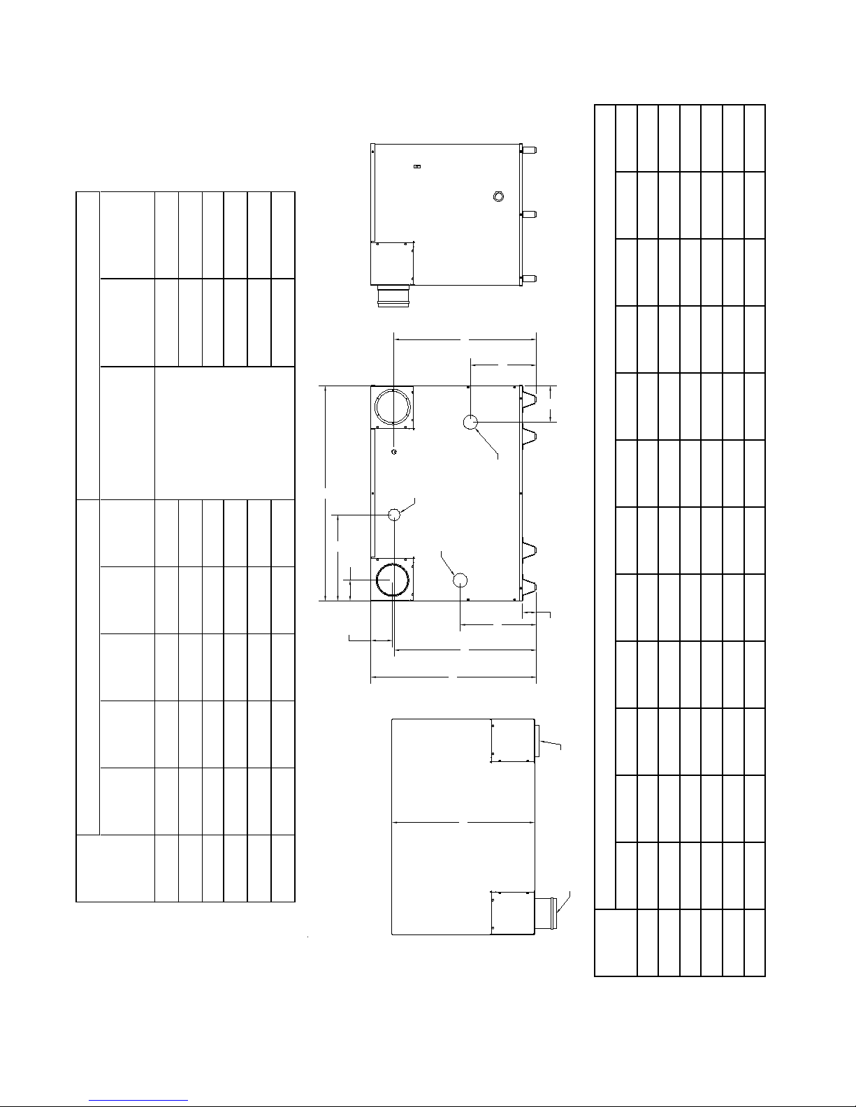
(Amps)
REAR VIEW
TOP VIEW
SIDE VIEW
L
(TYP.)
L
(TYP.)
C
2.71
E
D
B
K
A
13.00
H
M VENT
OUTLET
F OULET
WATER
F INLET
WATER
G INLET GAS
J
M VENT
INLET
Amp Draw
Rated Blower
(HP)
Rated Motor
Horse Power
Electrical Supply
(Voltz/Hertz/Phase)
Wet
(lbs.)
Weight
Dry
(lbs.)
Weight
Water
Volume
(Gallons)
BTU
(MBH)
Output
General Ratings and Capacities
(MBH)
BTU Input
Boiler
Model
SOL-300 300 252 1.1 288.5 297.7 3/4 8.5
SOL-500 500 420 1.3 316.0 326.8 3/4 8.5
SOL-750 750 637.5 2.4 508.5 528.5 120/60/1 3/4 8.0
SOL-1000 1000 850 2.6 548.5 570.2 3/4 8.0
SOL-1250 1250 1062.5 2.9 620.0 644.2 1-1/8 12
SOL-1500 1500 1275 3.3 713.0 740.5 1-1/8 12
Dimensions
‘A’ ‘B’ ‘C’ ‘D’ ‘E’ ‘F’ ‘G’ ‘H’ ‘J’ ‘K’ ‘L’ ‘M’
Boiler
Model
SOL-300 27.8 32.6 28.1 25.9 15.0 2.0 1.00 4.1 29.3 17.0 4.1 4.0
SOL-500 42.6 32.6 28.1 28.0 15.0 2.0 1.00 7.2 27.8 17.0 4.1 6.0
SOL-750 41.4 36.9 31.8 32.4 13.0 3.0 1.00 3.5 32.1 23.6 6.2 8.0
SOL-1000 49.4 36.9 31.8 32.4 13.0 3.0 1.25 3.5 32.1 21.6 6.2 8.0
SOL-1250 61.6 36.9 31.8 32.4 13.0 3.0 1.25 3.5 32.1 26.5 6.2 10.0
Figure 1: Dimensions
SOL-1500 73.9 36.9 31.8 32.4 13.0 3.0 1.50 3.5 32.1 25.6 6.2 10.0
5

I. Pre-Installation
WARNING
If you do not follow these instructions ex-
actly, a re or explosion may result causing
property damage or personal injury.
DANGER
Do not install boiler where gasoline or other
ammable vapors or liquids, or sources
of hydrocarbons (i.e. bleaches, cleaners,
chemicals, sprays, paint removers, fabric
softeners, etc.) are used or stored.
NOTICE
E. Protect gas ignition system components from water
(dripping, spraying, rain, etc.) during boiler operation
and service (circulator replacement, condensate trap,
control replacement, etc.).
F. Provide combustion and ventilation air in accordance
with sections 5.3 of the National Fuel Gas code,
ANSIZ223.1/NFPA 54, or sections 7.2, 7.3, or 7.4 of
CAN/CSA B149.1, Natural Gas and Propane Installation code, or applicable provisions of the local building
codes.
WARNING
Adequate combustion and ventilation air
must be provided to assure proper combustion.
Due to the low water content of the boiler,
mis-sizing of the boiler with regard to the
heating system load will result in excessive
boiler cycling and accelerated component
failure. Thermal Solutions DOES NOT
warrant failures caused by mis-sized boiler
applications. DO NOT oversize the boiler
to the system. Modular boiler installations
greatly reduce the likelihood of boiler oversizing.
A. Installation must conform to the requirements of the
authority having jurisdiction. In the absence of such
requirements, installation must conform to the Na-
tional Fuel Gas Code, NFPA 54/ANSI Z223.1, and/or
CAN/CGA B149 Installation Codes. Where required
the installation must conform to the standard for con-
trols and safety devices for automatically red boilers,
ANSI/ASME CSD-1.
B. Appliance is design certied for installation on combus-
tible ooring. Do not install boiler on carpeting.
C. Provide clearance between boiler jacket and combus-
tible material in accordance with local re ordinance.
Refer to Figure 1 for minimum listed clearance from
combustible material. Recommended service clearance
is 24 inches from left side, right side and front. Recommended service clearance is 36” at rear of unit. Service clearances may be reduced to minimum clearances
to combustible materials.
The following guideline is based on the National Fuel Gas
Code, NFPA 54/ANSI Z223.1.
1. Determine volume of space (boiler room). Rooms
communicating directly with space (through openings not furnished with doors) are considered part of
space.
Volume [ft³] = Length [ft] x Width [ft] x Height [ft]
2. Determine Total Input of all appliances in space.
Round result to nearest 1,000 Btu per hour (Btuh).
3. Determine type of space. Divide Volume by Total
Input.
a. If result is greater than or equal to 50 ft³ per
1,000 Btuh, space is considered an unconned
space.
b. If result is less than 50 ft³ per 1,000 Btuh, space
is considered a conned space.
4. Determine building type. A building of unusually
tight construction has the following characteristics:
a. Walls and ceiling exposed to outside atmosphere
have a continuous water vapor retarder with a
rating of 1 perm or less with openings gasketed
and sealed, and;
b. Weather-stripping has been added on openable
windows and doors, and;
c. Caulking or sealants applied in joints around
window and door frames, between sill plates and
oors, between wall-ceiling joints, between wall
panels, at plumbing and electrical penetrations,
and at other openings.
D. Install on level oor. Floor must be able to support
weight of boiler, water and all additional system components.
6
5. For boiler located in an unconned space in a
building of other than unusually tight construction, adequate combustion and ventilation air
is normally provided by fresh air inltration
through cracks around windows and doors.
6. For boiler located within unconned space in
building of
within equate conned space, provide outdoor
air through two permanent openings which
communicate directly or by duct with the
outdoors or spaces (crawl or attic) freely commu nicating with the outdoors. Locate one opening
within twelve (12) inches of top of space. Locate
remaining opening within twelve (12) inches of
bottom of space. Minimum dimension of air
opening is three (3) inches. Size each opening
per following:
a. Direct communication with outdoors. Minimum
free area of one (1) square inch per 4,000 Btu per
hour input of all equipment in space.
b. Vertical ducts. Minimum free area of one (1)
square inch per 4,000 Btu per hour input of all
equipment in space. Duct cross-sectional area
shall be same as opening free area.
c. Horizontal ducts. Minimum free area of one (1)
square inch per 2,000 Btu per hour input of all
equipment in space. Duct cross-sectional area
shall be same as opening free area.
unusually tight construction, or
Alternate method for boiler located within
conned space. Use indoor air if two permanent
openings communicate directly with additional
space(s) of sufcient volume such that combined
volume of all spaces meet criteria for unconned
space. Size each opening for minimum free area
of one (1) square inch per 1,000 Btu per hour
input of all equipment in spaces, but not less than
100 square inches.
7. Combustion Air/Ventilation Duct Louvers and
Grilles. Equip outside openings with louvers to
prevent entrance of rain and snow, and screens to
prevent entrance of insects and rodents. Louvers and
grilles must be xed in open position or interlocked
with equipment to open automatically before burner
operation. Screens must not be smaller than ¼ inch
mesh.
Consider the blocking effect of louvers, grilles and
screens when calculating the opening size to provide
the required free area. If free area of louver or grille
is not known, assume wood louvers have 20-25
percent free area and metal louvers and grilles have
60-75 percent free area.
CAUTION
Avoid operating this boiler in an environment where saw dust, loose insulation bers, dry wall
dust, etc. are present. If boiler is operated under these conditions, the burner interior and ports
must be cleaned and inspected daily to insure proper operation.
II. Unpack Boiler
CAUTION
Do not drop boiler. Do not bump boiler
jacket against the oor.
A. Move boiler to approximate installed position.
B. Remove all crate fasteners.
C. Lift and remove outside container. Save two of the
wooden slats from the container sleeve for use in Steps
E and F.
D. Remove all boiler hold-down fasteners.
Installation of this boiler should be undertaken only by trained and skilled personnel
from a qualied service agency.
E. Tilt the boiler to its front side or back side and slide a
wooden slat under the raised feet.
F. Tilt the boiler in the opposite direction and slide another
wooden slat under the raised feet.
G. Slide the boiler left or right off the skid using the two
wooden slats as runners.
H. Move boiler to its permanent location.
WARNING
7
III. Venting / Air Intake Piping
WARNING
Do not use this boiler with galvanized, non metallic or any other venting material that is not de-
signed for condensing ue gas applications.
Do not use a drafthood with this appliance.
Do not use vent dampers with this boiler.
Moisture and ice may form on surfaces around termination. To prevent deterioration, surfaces
should be in good repair (sealed, painted, etc.).
This appliance needs fresh air for safe operation and must be installed so there are provisions
for adequate combustion and ventilation air.
Do not reduce size of air intake pipe.
Read, understand and follow combustion air instruction restrictions contained in the Pre-Installa-
tion instructions of this manual.
Do not operate appliance where gasoline or other ammable vapors or liquids, or sources of
hydrocarbons (i.e. bleaches, cleaners, chemicals, sprays, paint removers, fabric softeners, etc.)
are used, stored and/or present in the air.
When installing vent pipe through chimney, no other appliance can be vented into the chimney.
Do not exceed maximum vent/air intake lengths. Refer to Table 1.
A. Vent Guidelines Due to Removal of an Ex-
isting Boiler
For installations not involving the replacement of an
existing boiler, proceed to Step B.
When an existing boiler is removed from a common
venting system, the common venting system is likely to
be too large for proper venting of the remaining appliances. At the time of removal of an existing boiler, the
following steps shall be followed with each appliance
remaining connected to the common venting system
placed in operation, while the other appliances remaining connected to the common venting system are not in
operation:
1. Seal any unused openings in the common venting
system.
2. Visually inspect the venting system for proper size
and horizontal pitch and determine there is no
blockage or restriction, leakage, corrosion, and
other deciencies which could cause an unsafe
condition.
3. Insofar as is practical, close all building doors and
windows and all doors between the space in which
the appliances remaining connected to the common
venting system are located and other spaces of the
building. Turn on clothes dryers and any appliance
not connected to the common venting system.
Turn on any exhaust fans, such as range-hoods
and bathroom exhausts, so they will operate at
8
maximum speed. Do not operate a summer exhaust
fan. Close replace dampers.
4. Place in operation the appliance being inspected.
Follow the Lighting (or Operating) Instructions.
Adjust thermostat so appliance will operate
continuously.
5. Test for spillage at the draft hood relief opening
after ve (5) minutes of main burner operation. Use
the ame of a match or candle, or smoke from a
cigarette, cigar or pipe.
6. After it has been determined that each appliance
remaining connected to the common venting
system properly vents when tested as outlined
above, return doors, windows, exhaust fans, re
place dampers and any other gas burning appliance
to their previous conditions of use.
7. Any improper operation of the common venting
system should be corrected so the installation
conforms with the National Fuel Gas Code, NFPA
54/ANSI Z223.1 and/or CAN/CSA B149.1 Natural
Gas and Propane Installation Code. When resizing
any portion of the common venting system, the
common venting system should be resized to approach the minimum size as determined using the
appropriate tables in Part 11 of the National Fuel
Gas Code, ANSI Z223.1/NFPA 54 and/or CAN/CSA
B149.1 Natural Gas and Propane Installation Code.

B. General Guidelines
1. Vent system installation must be in accordance with
Part 7, Venting of Equipment of the National Fuel
Gas Code, ANSI Z223.1/NFPA 54, or Section 7,
Venting Systems and Air Supply for Appliances of
the CAN/CSA B149.1, Natural Gas and Propane Installation Code, or applicable provisions of the local
building codes.
2. Contact local building or re ofcials about restrictions and installation inspection in your area.
3. Refer to the appropriate drawings in this section of
this manual to determine the proper conguration of
venting system. Figures 2 thru 11. The vent system
shall be installed in accordance with the instructions
listed in this manual.
4. This appliance requires a Special Gas Vent. The
product is designed to use AL 29-4C® Stainless
Steel or other Stainless Steel material approved for
condensing ue gas applications. The boilers are
shipped with AL 29-4C® vent adapter to directly
connect to Heat Fab Saf-T-Vent. The use of alternate manufacturer’s venting systems will require
adapters and vent terminal. These adapters are not
supplied with this unit and should be obtained from
the supplier of alternate venting system.
5. The venting system must be installed so as to
prevent accumulation of condensate. Horizontal
vent pipe must maintain a minimum ¼ inch per foot
slope down towards boiler.
a. Do not manifold condensate drains.
b. A common condensate pump/sump may be used.
Run separate condensate piping from each vent
drain to the sump. A common drain may be used
to discharge condensate from the sump.
Consult pump/sump manufacturer for compat-
ibility of materials of construction with ue gas
condensate. If a common pump/sump is used,
individual vent drain lines must be connected
such that one drain pipe cannot back feed into
another vent drain.
c. Consult local authorities regarding disposal of
ue gas condensate into public waste water system. Some jurisdictions require that the condensate be buffered before discharge. this buffering
is commonly achieved by draining the condensate through a limestone bed. Consult chemical
treatment company for buffering systems.
6. Use noncombustible ¾ inch pipe strap to support
horizontal runs and maintain vent location and
slope while preventing sags in pipe. Do not restrict
thermal expansion or movement of vent system.
Maximum support spacing is ve (5) feet. Do not
penetrate any part of the vent system with fasteners.
7. Vent length restrictions are based on equivalent
length of vent/air pipe (total length of straight
pipe plus equivalent length of ttings). Maximum
vent/air lengths are listed in Table 1. Do not exceed
Table 1: Vent & Air Intake Length
Vent/Air Intake
Pipe Dia.Min Max
Boiler Model
SOL-300 5 50 4
SOL-500 5 78 6
SOL-750 5 50 8
SOL-1000 5 50 8
SOL-1250 5 50 10
SOL-1500 5 50 10
maximum vent/air intake lengths. Refer to vent
manufacturer’s recommendations for the equivalent
length of ttings.
8. Provide and maintain vent pipe minimum clearances
to combustible materials. Vent pipe minimum clearance to combustible material is four (4) inches when
vent is installed in a fully enclosed (chase) application or three (3) inches when vent is installed with
at least one side open, similar to a joist bay application. Use double wall thimble when penetrating a
combustible wall. Some examples of Wall thimble
manufactures are American Metal Products, Hart &
Cooley, and Metal Fab.
9. Do not install venting system components on the ex-
terior of the building except as specically required
by these instructions. The vent termination location
is restricted as follows:
a. The minimum distance from adjacent public
walkways, adjacent buildings, openable win
dows and building openings shall not be less
than those values specied in the National Fuel
Gas Code, ANSI Z223.1/NFPA 54 and/or CAN/
CSA B149.1, Natural Gas and Propane Installa
tion Code.
b. Minimum twelve (12) inches above grade plus
normally expected snow accumulation level, or
seven (7) feet above grade if located adjacent to
public walkway. Do not install over public walkway where local experience indicates appliance
ue gas vapor or condensate creates a nuisance
or hazard.
c. Minimum three (3) feet above any forced air
inlet located within ten (10) feet.
d. Power Vent - Minimum four (4) feet below, four
(4) feet horizontally from, or four (4) feet above
any door, window, or gravity air inlet.
ft. ft. In.
9

e. Minimum of four (4) feet horizontally from, and
in no case above or below, unless a 4 foot horizontal distance is maintained from electric meters, gas meters, regulators and relief equipment.
This distance may be reduced if equipment is
protected from damage due to condensation or
vapor by enclosure, overhangs, etc.
f. Minimum twelve (12) inches from overhang or
corner of building.
g. The vent termination shall be located such that
no damage to building materials will occur from
Figure 2: Vent Therminal Location
NOTICE
Cut must be square with pipe and led or
sanded smooth before joining. Carefully
ensure roundness of cut pipe by hand with
gloves before installing. Seal joint with RTV
specied in this manual.
ue gasses degradation.
10. Enclose vent passing through occupied or unoccu
pied spaces above the boiler with material having a
re resistance rating of at least equal to the rating
of the adjoining oor or ceiling. Maintain minimum
clearances to combustible materials. See page 4.
11. Plan venting system to avoid possible contact with
plumbing or electrical wires. Start at vent connector
on top of boiler and work towards vent terminal.
12. Once a vent pipe manufacturer and system is chosen never mix and match vent systems.
13. Field Supplied Vent Terminations (One per boiler)
a. Horizontal - Use Saf-T Vent mitered termination
with screen or equivalent
b. Vertical - Use Saf-T Vent rain cap or equivalent
C. Supplemental Vent Terminal Location In-
structions (Massachusetts Code Only)
The Commonwealth of Massachusetts requires compli-
ance with regulation 248 CMR 4.00 and 5.00 for installation of side-wall vented gas appliances as follows:
(a) For all side wall horizontally vented gas fueled equip-
ment installed in every dwelling, building or structure
used in whole or in part for residential purposes, including those owned or operated by the Commonwealth and
where the side wall exhaust vent termination is less than
seven (7) feet above nished grade in the area of the
venting, including but not limited to decks and porches,
the following requirements shall be satised:
1. INSTALLATION OF CARBON MONOXIDE DETECTORS. At the time of installation of the side wall
horizontal vented gas fueled equipment, the installing
plumber or gastter shall observe that a hard wired
carbon monoxide detector with an alarm and battery
back-up is installed on the oor level where the gas
equipment is to be installed. In addition, the install-
ing plumber or gastter shall observe that a battery
operated or hard wired carbon monoxide detector with
an alarm is installed on each additional level of the
dwelling, building, or structure served by the side wall
horizontal vented gas fueled equipment. It shall be the
responsibility of the property owner to secure the services of qualied licensed professionals for the installation of hard wired carbon monoxide detectors.
a. In the even that the side wall horizontally vented
gas fueled equipment is installed in a crawl space or
an attic, the hard wired carbon monoxide detector with
alarm and battery back-up may be installed on the next
adjacent oor level.
b. In the event that the requirements of this subdivision
can not be met at the time of completion of installation, the owner shall have a period of thirty (30) days
to comply with the above requirements; provided, however, that during said thirty (30) day period, a battery
operated carbon monoxide detector with an alarm shall
be installed.
2. APPROVED CARBON MONOXIDE DETECTORS.
Each carbon monoxide detector as required in accordance with the above provisions shall comply with
NFPA 720 and be ANSI/UL 2034 listed and IAS certi-
ed.
3. SIGNAGE. A metal or plastic identication plate shall be
permanently mounted to the exterior of the building at
a minimum height of eight (8) feet above grade directly
in line with the exhaust vent terminal for the horizontally vented gas fueled heating appliance or equipment.
The sign shall read, in print size no less than one-half
(1/2) inch in size, “GAS VENT DIRECTLY BELOW,
KEEP CLEAR OF ALL OBSTRUCTIONS”.
4. INSPECTION. The state or local gas inspector of the side
wall horizontally vented gas fueled equipment shall
not approve the installation unless, upon inspection,
10

the inspector observes carbon monoxide detectors and
signage installed in accordance with the provisions of
248 CMR 5.08(2)(a)1 through 4.
(b) EXEMPTIONS: The following equipment is exempt
from 248 CMR 5.08(2)(a)1 through 4:
1. The equipment listed in Chapter 10 entitled “Equipment Not Required To Be Vented” in the most current
edition of NFPA 54 as adopted by the board; and
2. Product Approved side wall horizontally vented
gas fueled equipment installed in a room or structure
separate from the dwelling, building or structure used in
whole or in part for residential purposes.
(c) MANUFACTURER REQUIREMENTS - GAS
EQUIPMENT VENTING SYSTEM PROVIDED.
When the manufacturer of Product Approved side wall
horizontally vented gas equipment provides a venting
system design or venting system components with the
equipment, the instructions provided by the manufacturer for installation of the equipment and the venting
system shall include:
1. Detailed instructions for the installation of the venting system design or the venting system components;
and
2. A complete parts list for the venting system design or
venting system.
(d) MANUFACTURER REQUIREMENTS - GAS
EQUIPMENT VENTING SYSTEM NOT PROVIDED.
When the manufacturer of a Product Approved side
wall horizontally vented gas fueled equipment does not
provide the parts for venting the ue gasses, but identies “special venting systems”, the following requirements shall be satised by the manufacturer:
1. The referenced “special venting system” instructions shall be included with the appliance or equipment
installation instructions; and
2. The “special venting systems” shall be Product
Approved by the Board, and the instructions for that
system shall include a parts list and detailed installation
instructions.
(e) A copy of all installation instructions for all Product
Approved side wall horizontally vented gas fueled
equipment, all venting instructions, all parts lists for
venting instructions, and/or all venting design instructions shall remain with the appliance or equipment at
the completion of the installation.
D. Separate Horizontal Venting System. See
Figures 3, 4 and 5.
1. Vent Piping –
a. Do not exceed maximum vent/air intake
lengths. Refer to Table 1.
b. Recommended horizontal installation consists
of vent being sloped down ¼ inch per foot
toward boiler.
c. Use appropriate designed thimbles when
passing through combustible walls (thimble
use optional for noncombustible walls). Insert
thimble through wall from outside. Secure
outside ange to wall with nails or screws, and
seal ID, OD and vent holes with sealant
material. Install inside ange to inside wall,
secure with nails or screws, and seal with
sealant material.
d. For noncombustible wall application when
thimble is not used, size opening such that bell
with locking band attached cannot pass
through.
e. Join vent terminal to vent pipe. Locate vent
pipe such that vent terminal is between six (6)
inches and twenty-four (24) inches from wall
when joined to inside vent piping. See Figure
3 or 4.
f. Insert vent pipe through thimble/opening from
outside and join to vent system. Apply seal ant between vent pipe and opening/thimble to
provide weathertight seal.
2. Side Vent Installation. See gure 5.
a. Horizontal vent/air intake runs with no
vertical rise in piping allowed.
b. Do not exceed maximum vent/air intake
lengths. Refer to Table 1.
c. Recommended Horizontal Installation only
consists of vent/air intake sloped down 1/4
inch per foot toward termination.
d. Thimbles, same as “C” above in section D.1
e. same as “D” above in section D.1
f. same as “E” above in section D.1
g. same as “F” above in section D.1
Figure 3: Side Top Vent
11

12
Figure 4: Recommended Separate Horizontal - Vent/Air Intake Installation

Figure 5: Side Vent
13

E. Optional Separate Horizontal Vent Terminal Mounting – See Figure 6
1. Do not exceed maximum vent/air intake lengths.
Refer to Table 1.
2. This installation will allow a maximum of ve (5)
feet vertical exterior run of the vent/air intake piping
to be installed on separate horizontal venting and
indoor air horizontal venting.
Note: Exterior run to be included in equivalent vent/
air intake lengths.
3. Install vent piping.
a. Install vent piping for desired venting system.
Refer to specic section for details for vent pipe
installation.
b. After penetrating wall/thimble, install a 90°
elbow so that elbow leg is in the up direction.
c. Install maximum of ve (5) feet of vent pipe.
Refer to Sections C through E for proper proce-
dures for joining vent pipe and ttings.
d. At top of vent pipe length install a 90° elbow so
that elbow leg is opposite the building’s exterior
surface.
e. Install 45° elbow to upper 90° elbow so that leg
of 45° is in down direction (see Figure 6). If not
using indoor air, proceed to Step f.
f. Install horizontal vent terminal.
g. Brace piping if required.
4. Air Intake Piping (not required for indoor air).
a. Install air intake piping for desired venting sys-
tem. Refer to specic section for details for air
intake installation.
b. After penetrating wall, install a corrosion re-
sistant 90o elbow so that elbow leg is in the up
direction.
c. Install maximum of ve (5) feet of corrosion
resistant air intake pipe.
d. At top of air intake pipe install air intake termi
nal (provided with boiler).
e. Brace piping if required.
-
14
Figure 6: Optional Indoor Air – Vent Terminal Installation
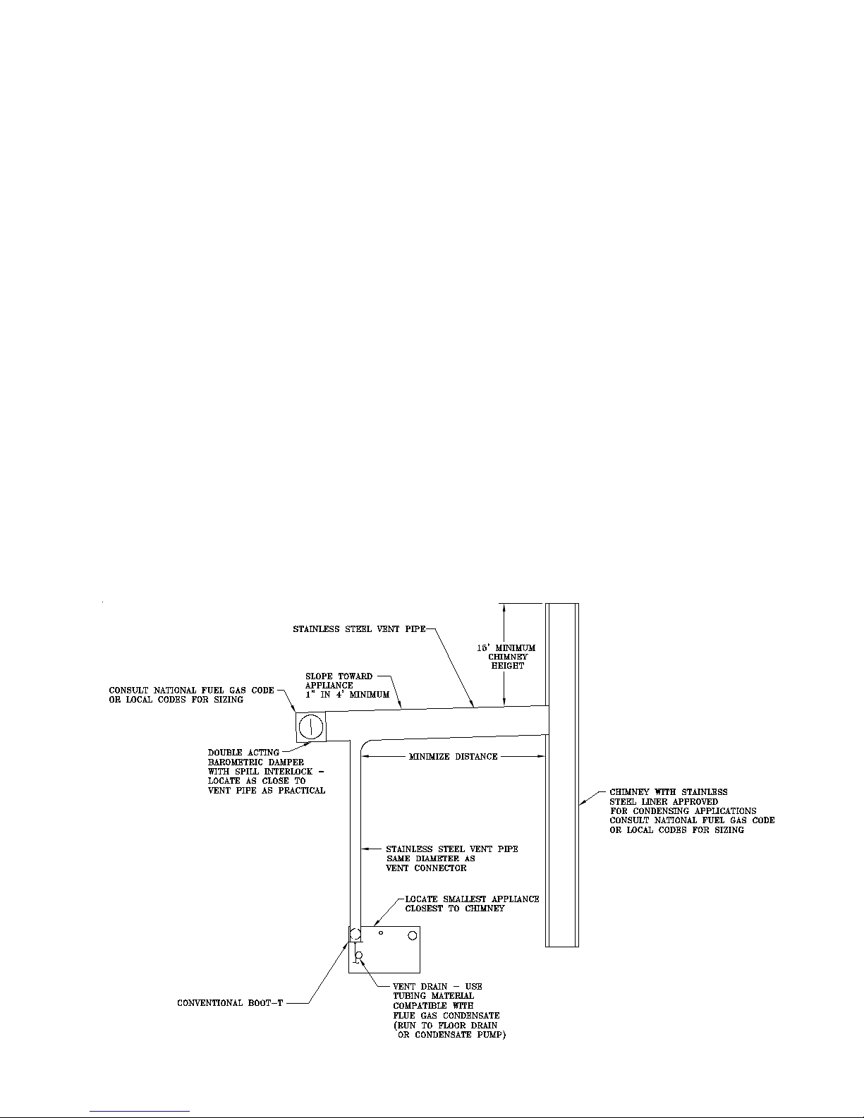
F. Conventional Venting (Negative Draft) – See Figure 7
a. The minimum chimney height is 15 feet.
b. The chimney must be protected from down
drafts, rain and debris by using a chimney cap or
star.
c. Start installing vent at vent cap and continue
installation toward the boiler.
d. The ue connector and chimney ue diameter
may need to be increased or decreased depend
ing on the dimensions of the boiler. Consult the
National Fuel Gas Code or Local Codes for siz-
ing. Boiler input, ue connector lateral distance
and chimney height affect the ue connector or
chimney ue diameters.
e. A double acting barometric damper with integral
ue spillage interlock switch must be used when
the boiler is vented conventionally.
f. The chimney and ue connector must be sized
and congured to provide a minimum - 0.04 inch
w.c. draft at the vent outlet of the boiler.
g. Maintain a minimum vertical pitch of one (1)
inch in four (4) feet of vent connector run.
G. Air Intake Piping - See Figure 4 & 8
1. Locate air intake termination on the same wall as the
vent termination if possible, to prevent nuisance boiler
shutdowns. However, boiler may be installed with vertical venting and sidewall combustion air inlet or vice
versa, if installation conditions do not allow alternate
arrangement.
2. Do not exceed maximum air intake length. See Table 1.
3. Use single wall metal pipe and ttings or thin wall PVC
available at most heating distributors.
4. Air intake termination must be located: Horizontal - At
least twelve (12) inches above grade plus the expected
snow accumulation.
5. Start at collar on burner enclosure (inside boiler jacket)
and work towards the air intake terminal.
6. Maintain minimum of 1/4 inch per foot slope on
horizontal runs. Slope towards air inlet terminal when
possible. If not, slope towards boiler.
7. The air intake pipe must be adequately supported with
straps or supports no less than ve (5) feet apart on
horizontal runs. The complete air intake piping system
must be rigid and able to withstand minor impacts without collapse.
8. Inlet air pipe penetration: Horizontal - Size wall penetration to allow easy insertion of air inlet piping. Seal
around pipe with sealant to form weathertight exterior
joint.
9. Seal all joints airtight, using silicone caulk or self-adhesive aluminum tape.
10. Install Air Intake Terminal.
Figure 7: Conventional Venting (Negative Draft)
15

16
SEE TABLE 1.
Figure 8: Separate Horizontal – Vent/Air Intake Terminal Conguration

H. Separate Vertical Venting System - See Figures 9, 10, and 11.
Vertical Venting –
1. Do not exceed maximum vent lengths. Refer to
Table 1.
2. Slope horizontal runs minimum ¼ inch per foot
down towards boiler.
3. Install re stops where vent passes through oors,
ceilings or framed walls. The re stop must close
the opening between the vent pipe and the structure.
Fire stop manufacturers are Air-Jet, American Metal
Products, Metal-Fab, and Simpson Dura-Vent.
4. Whenever possible, install vent straight through the
roof. Refer to Figure 9 if offset is necessary. Maintain minimum clearance to combustible
materials.
5. Install Vent Terminal.
a. Size roof opening to maintain minimum clear-
ance from combustible materials.
b. Extend vent pipe to maintain minimum vertical
and horizontal distance of twelve (12) inches
from roof surface. Allow additional vertical distance for expected snow accumulation. Provide
brace as required. Refer to Figure 11.
c. Vertical venting requires use of the roof ashing
and storm collar to prevent moisture from entering the structure.
d. Install storm collar on vent pipe immediately
above ashing. Apply Dow Corning Silastic 732
RTV Sealant between vent pipe and storm collar
to provide weathertight seal.
e. Attach vent terminal.
Vertical Air Intake Piping –
1. Do not exceed maximum air intake length. Refer to
Table 1.
2. Locate air intake termination on the same roof loca
tion as the vent termination if possible, to prevent
nuisance boiler shutdowns. However, boiler may be
installed with vertical venting and sidewall combustion air inlet or vica versa, if installation conditions
do not allow alternate arrangement.
-
8. Inlet air pipe penetration:
9. Seal all joints airtight, using silicone caulk or self -
adhesive aluminum tape.
10. Install Air Intake Terminal:
Vertical - Insert intake piping into intake terminal
collar. Secure terminal to intake piping and seal
joint with silicone caulk.
with straps or supports no less than ve (5) feet
apart on horizontal runs. The complete air intake
piping system must be rigid and able to withstand
minor impacts without collapse.
Vertical - Size roof opening to allow easy insertion
of inlet piping and allow proper installation of ashing and storm collar.
a. Use appropriately designed vent ashing when
passing through roofs. Follow ashing manufac-
turers’ instructions for installation procedures.
Flashing manufacturers are Air-Jet, American
Metal Products, Metal Fab, and Simpson DuraVent.
b. Extend air intake pipe to maintain minimum
vertical and horizontal distance of twelve (12)
inches from roof surface. Allow additional vertical distance for expected snow accumulation.
Provide brace as required. Refer to Figure 11.
c. Vertical air intake requires ashing and a storm
collar to prevent moisture from entering the
structure.
d. Install storm collar on air intake pipe immediate-
ly above ashing. Apply Dow Corning Silastic
732 RTV Sealant between air intake pipe and
storm collar to provide weathertight seal.
3 Use single wall metal pipe and ttings or thin wall
PVC available at most heating distributors.
4. Air intake termination must be located:
Vertical - At least twelve (12) inches above the roof
surface plus the expected snow accumulation.
5. Start at collar on burner enclosure (inside boiler
jacket) and work towards the air intake terminal.
6. Maintain minimum of 1/4 inch per foot slope on
horizontal runs. Slope down towards boiler.
7. The air intake pipe must be adequately supported
17

18
Figure 9: Vertical Vent Installation

Figure 10: Attic Offset
Figure 11: Indoor Air - Horizontal / Vertical Vent Terminal Installation
Extend Vent/Air Intake Piping to maintain minimum vertical (“X”) and minimum horizontal (“Y”) distance of twelve
(12) inches from roof surface. Allow additional vertical (“X”) distance for expected snow accumulation.
19

IV. Water Piping and Trim
CAUTION
iii. Oxygen permeable materials in the distribu-
tion system.
Failure to properly pipe boiler may result in
improper operation and damage to boiler or
structure.
1. Design and install boiler and system piping to
prevent oxygen contamination of boiler water and
frequent water additions.
CAUTION
Oxygen contamination of boiler water will
cause corrosion of iron and steel boiler
components, and can lead to boiler failure. Thermal Solutions Standard Warranty
does not cover problems caused by oxygen contamination of boiler water or scale
(lime) build-up cause by frequent addition of
water.
CAUTION
All piping either new or existing must be
cleaned with a tri sodium phosphate (TSP)
solution to remove mill scale and oils from
the system. Failure to do so could result in
premature failure of the heat exchanger (not
covered by Thermal Solutions warranty.)
CAUTION
On an existing or retrot system, a lter or
strainer must be installed on the system
return prior to the boilers.
b. In order to insure long product life, oxygen
sources must be eliminated. This can be accomplished by taking the following measures:
i. Repairing system leaks to eliminate the need
for addition of make-up water.
ii. Eliminating and/or repairing ttings which
allow oxygen absorption.
iii. Using non-permeable materials in the distri-
bution system.
iv. Isolating the boiler from the system water by
installing a heat exchanger.
vi. Using properly designed and operating air
elimination devices in water piping.
2. Design and install system piping to prevent return
water temperatures below 130°F. Refer to Table 2
for boiler ow and pressure drop requirements.
3. Connect system supply and return piping to boiler.
Refer to Figure 12. Also consult I=B=R Installation
CAUTION
Return water temperature below 130°F
will cause ue gas condensation inside the
boiler. Flue gas condensate can lead to
boiler failure. Thermal Solutions Standard
Warranty does not cover problems caused
by ue gas condensation.
WARNING
CAUTION
When using Glycol products, all Glycol
manufacturers’ requirements, including
rust inhibitors, must be adhered. Max 50%
Glycol.
a. There are many possible causes of oxygen con-
tamination such as:
i. Addition of excessive make-up water as a
result of system leaks.
ii. Absorption through open tanks and ttings.
20
Supply and return water temperature differences greater than 40°F can lead to boiler
failure. Thermal Solutions Standard Warranty does not cover problems caused by
temperature difference greater than 40°F.
and Piping Guides. Maintain ½” minimum distance
between water piping and combustible material.
Consult Thermal Solutions for unusual system
requirements.
4. A pressure relief valve is supplied with each appliance. No valve is to be placed between the relief
valve and appliance. No reducing coupling or other
restriction shall be installed in the discharge line.

See Figure 13.
compatible with local environmental regulations.
a. Pipe the safety relief discharge to a suitable place
for disposal when relief occurs.
b. Do not install reducing couplings for other
restrictive devices in the safety relief discharge
line.
c. The safety relief discharge line must allow for
complete drainage of both the valve and line.
5. If the relief valve discharges periodically, this may
be due to thermal expansion in a closed water
supply system. Contact the water supplier or local
plumbing inspector on how to correct this situation.
DO NOT PLUG THE RELIEF VALVE.
6. Install the drain valve provided with the appliance at
the lowest elevation. See Figure 13.
7. If this boiler is used in connection with refrigeration systems, the boiler must be installed so that the
chilled medium is piped in parallel with the boiler
using appropriate valves to prevent the chilled
medium from entering the boiler, see gure 13A.
Also consult I=B=R Installation and Piping Guides.
If this boiler is connected to heating coils located
in air handling units where they may be exposed to
refrigerated air circulation, the boiler piping must be
equipped with ow control valves or other automatic means to prevent gravity circulation of boiler
water during operation of the cooling system.
8. Install water ow switch. Water ow switch must
be located such that water ow disruptions do not
affect switch operation. Maintain maximum practi-
cal straight piping before and after ow switch to
minimize water disruptions. Refer to manufactures’
instructions for proper paddle length.
9. A low water cutoff is required to protect a hot water
boiler when any connected heat distributor (radiation) is installed below the top of the hot water
boiler (i.e. baseboard on the same oor level as the
boiler). In addition, some jurisdictions require the
use of a LWCO with a hot water boiler. If a low
water cutoff is required, it must be mounted in the
system piping above the boiler. The minimum safe
water level of a hot water boiler is just above the
highest water containing cavity of the boiler; that is,
a hot water boiler must be full of water to operate
safely.
10. Oil, grease, and other foreign materials which
accumulate in new hot water boilers and a new or
reworked system should be boiled out, and then
thoroughly ushed. A local qualied water
treatment chemical specialist is a suggested source
for recommendations regarding appropriate
chemical compounds and concentrations which are
11. After the boiler and system have been cleaned and
ushed, and before relling the entire system add
appropriate water treatment chemicals, if necessary,
to bring the pH between 8.8 and 9.2.
12. If it is required to perform a long term pressure
test of the hydronic system, the boiler should rst
be isolated to avoid a pressure loss due to the
escape of air trapped in the boiler.
To perform a long term pressure test including the
boiler, ALL trapped air must rst be removed from
the boiler.
A loss of pressure during such a test, with no
visible water leakage, is an indication that the
boiler contained trapped air.
WARNING
Failure to operate the unit with the proper
water ow rate can lead to appliance failure.
Always install water ow switch so that the
unit stops operating if improper water ow
is present.
Safety relief valve discharge piping must
be piped such that the potential of severe
burns is eliminated. DO NOT pipe in any
area where freezing could occur. DO NOT
install any shut-off valves, plugs or caps.
Consult Local Codes for proper discharge
piping arrangement.
Do not operate boiler with ow rates in
excess of the maximum ow rates listed in
Table 2. Boiler tube erosion and pitting will
occur. Thermal Solutions Standard Warranty does not cover problems caused by
excessive water ow rates.
If a high head system pump is installed, assure that the boiler relief valve and system
piping are capable of operating properly
at the combined pressure of the system ll
pressure plus the pump static head pressure.
21
Table 2 - Solaris Boiler Flow and Pressure Drop
20° ΔT (max) 40° ΔT (min)
Boiler
Model
SOL-300 0.8 24 0.5 12 2
SOL-500 6.9 41 1.4 20 2
SOL-750 6.5 64 1.5 32 3
SOL-1000 16.1 85 3.7 43 3
SOL-1250 23.5 106 6.9 53 3
SOL-1500 29.1 128 10.6 64 3
Flow
(GPM) Δ P (ft)
Flow
(GPM)
Supply/Return
Pipe (in. dia.)Δ P (ft)
Figure 12: Water Piping (Single Boiler)
22
Figure 13: Safety & Drain Valve Installation
Figure 13 A: Recommended Piping for Combination
Heating & Cooling (Refrigeration) System
23
 Loading...