

Page 1
Price - $3.00
H
INSTALLATION, OPERATING AND
SERVICE INSTRUCTIONS
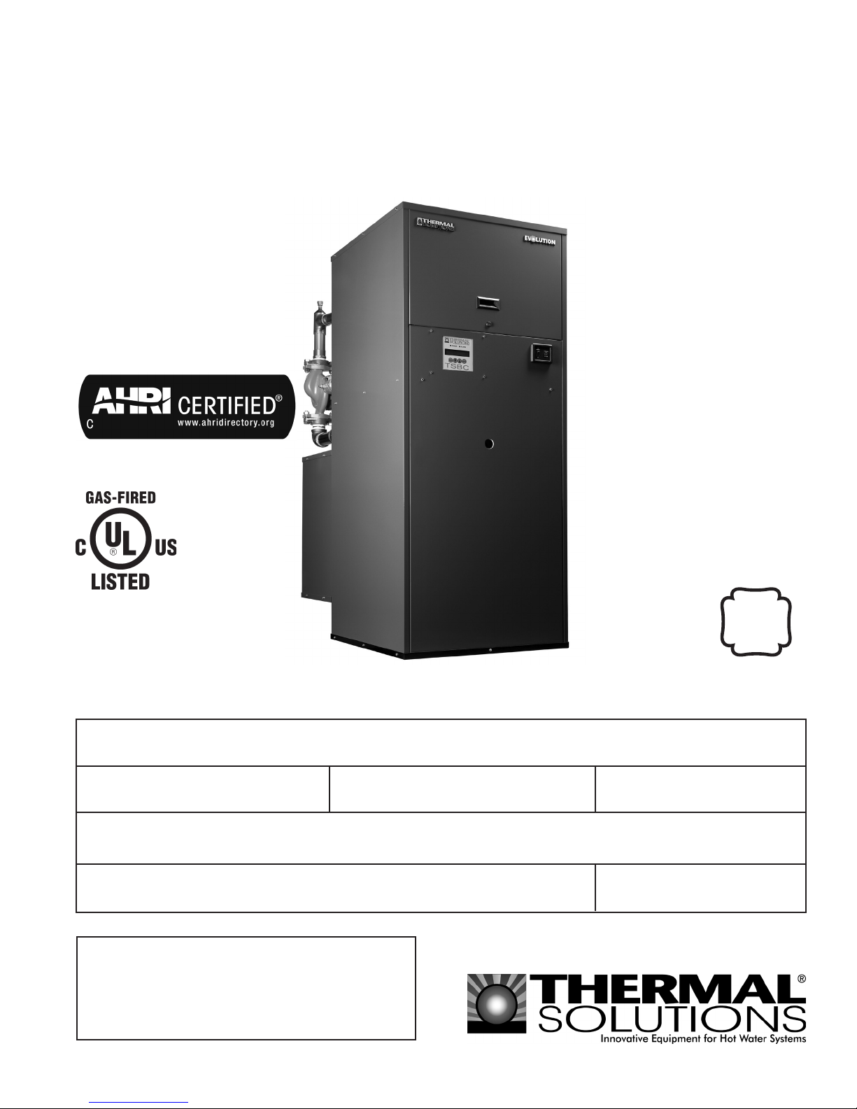
EVCA SERIES CONDENSING BOILER
A
S
M
E
File Number MH25585
For service and repairs to the heating plant, call your heating contractor. When seeking information on the
boiler from the manufacturer, provide boiler model and serial number as shown on rating label.
Boiler Model Installation Date
EVCA -
Heating Contractor
Your Local Thermal Solutions Representative:
Serial Number
Type System
Phone NumberAddress
814EVC003 R4-11/12
1
Page 2

IMPORTANT INFORMATION - READ CAREFULLY
NOTE: Post these instructions and maintain in legible condition.
NOTE: e equipment shall be installed in accordance with those installation regulations required in the area where the
installation is to be made. ese regulations shall be carefully followed in all cases. Authorities having jurisdiction
shall be consulted before installations are made.
All wiring on boilers installed in the USA shall be in accordance with the National Electrical Code and/or local regulations.
All wiring on boilers installed in Canada shall be in accordance with the Canadian Electrical Code and/or local regulations.
e following terms are used throughout this manual to bring attention to the presence of hazards of various risk levels, or to
important information concerning product life.
DANGER
Indicates an imminently hazardous situation
which, if not avoided, will result in death, serious
injury or substantial property damage.
WARNING
Indicates a potentially hazardous situation which,
if not avoided, could result in death, serious injury
or substantial property damage.
Indicates a potentially hazardous situation which,
if not avoided, may result in moderate or minor
injury or property damage.
Indicates special instructions on installation,
operation, or maintenance which are important
but not related to personal injury hazards.
CAUTION
NOTICE
DANGER
DO NOT store or use gasoline or other ammable vapors or liquids in the vicinity of this or any other
appliance.
If you smell gas vapors, DO NOT try to operate any appliance - DO NOT touch any electrical switch or use
any phone in the building. Immediately, call the gas supplier from a remotely located phone. Follow the gas
supplier’s instructions or if the supplier is unavailable, contact the re department.
2
Page 3
WARNING
This boiler requires regular maintenance and service to operate safely. Follow the instructions contained
in this manual.
Improper installation, adjustment, alteration, service, or maintenance can cause property damage, personal
injury or loss of life. Read and understand the entire manual before attempting installation, start-up,
operation, or service. Installation and service must be performed only by an experienced, skilled installer
or service agency.
This boiler must be properly vented.
This boiler needs fresh air for safe operation and must be installed so there are provisions for adequate
combustion and ventilation air.
The interior of the venting and air intake systems must be inspected and cleaned before the start of the
heating season and should be inspected periodically throughout the heating season for any obstructions.
Clean and unobstructed venting and air intake systems are necessary to allow noxious fumes that could
cause injury or loss of life to vent safely and will contribute toward maintaining the boiler’s efciency.
This boiler is supplied with safety devices which may cause the boiler to shut down and not re-start
without service - If damage due to frozen pipes is a possibility, the heating system should not be left
unattended in cold weather; or appropriate safeguards and alarms should be installed on the heating
system to prevent damage if the boiler is inoperative.
This boiler contains very hot water under high pressure. Do not unscrew any pipe ttings nor attempt
to disconnect any components of this boiler without positively assuring the water is cool and has no
pressure. Always wear protective clothing and equipment when installing, starting up or servicing this
boiler to prevent scald injuries. Do not rely on the pressure and temperature gauges to determine the
temperature and pressure of the boiler. This boiler contains components which become very hot when
the boiler is operating. Do not touch any components unless they are cool.
Boiler materials of construction, products of combustion and the fuel contain alumina, silica, heavy metals,
carbon monoxide, nitrogen oxides, aldehydes and/or other toxic or harmful substances which can cause
death or serious injury and which are known to the state of California to cause cancer, birth defects and
other reproductive harm. Always use proper safety clothing, respirators and equipment when servicing
or working nearby the appliance.
Failure to follow all instructions in the proper order can cause personal injury or death. Read all instructions,
including all those contained in component manufacturers manuals which are provided with the boiler
before installing, starting up, operating, maintaining or servicing.
Keep boiler area clear and free from combustible materials, gasoline and other ammable vapors or
liquids.
All cover plates, enclosures and guards must be in place at all times.
This product must be installed by a licensed plumber or gas tter when installed within the Commonwealth
of Massachusetts.
NOTICE
This boiler has a limited warranty, a copy of which is printed on the back of this manual. It is the responsibility
of the installing contractor to see that all controls are correctly installed and are operating properly when the
installation is complete.
3
Page 4

Table of Contents
I. Pre-Installation........................................... 8
II. Unpacking the Boiler ................................ 9
III. Installation ................................................ 10
A. Venting ................................................ 10
B. Combustion Air ................................. 15
C. Water Treatment ................................ 17
D. Water Piping and Trim ...................... 18
E. Gas Piping ........................................... 21
F. Electrical ............................................. 24
G. Modular Systems ................................31
H. Condensate Drains ............................ 40
IV. System Start-up ........................................ 41
V. Lighting Instructions ...............................44
VI. Boiler Operational Sequence ..................46
VII. Service/Maintenance ............................... 48
A. Safety and Operating Controls......... 49
B. Troubleshooting .................................50
C. Periodic Maintenance........................52
D. Inspection & Cleaning Procedure ... 53
VIII. Repair Parts .............................................56
IX. ermal Solutions Boiler Control™
(TSBC™) ...................................................85
A. Introduction .......................................85
B. Front Panel Display ........................... 86
C. Security Menu .................................... 88
D. Setup Menu .........................................89
E. Boiler Conguration Menu...............92
F. System Conguration Menu .............93
G. Setpoints Menu ..................................94
H. Communication Menu ..................... 95
I. Manual Mode Menu ...........................96
X. Warranty ................................... Back Cover
Minimum Clearance to Combustible Materials
Left Side Right Side Front Rear Top Flue Connector
6" 6" 24" 6" 6" 18"
Recommended Clearance for Service
Boiler Size Left Side or Right Side Front and Rear Top
750/1000 24" 24" 24" 24" 16"
1500 24" 24" 24" 24" 19"
2000 24" 24" 24" 24" 31"
3000 24" 24" 36" 36" 26.5"
NOTES:
1. When 3 or more units are mounted side-by-side, the front service clearance
increases by 12" and the rear service clearance increases by 24".
2. Verify clearances with local codes.
3. Net AHRI Ratings
A. The Net AHRI Water Ratings shown are based on a piping and pickup allowance of 1.15.
B. The manufacturer should be consulted before selecting a boiler for installations having unusual piping and
pickup requirements, such as intermittent system operation, extensive piping systems, etc.
C. The ratings have been determined under the provisions governing forced draft boiler-burner units.
4
Page 5
Notes:
1. Piping removed for visual clarity.
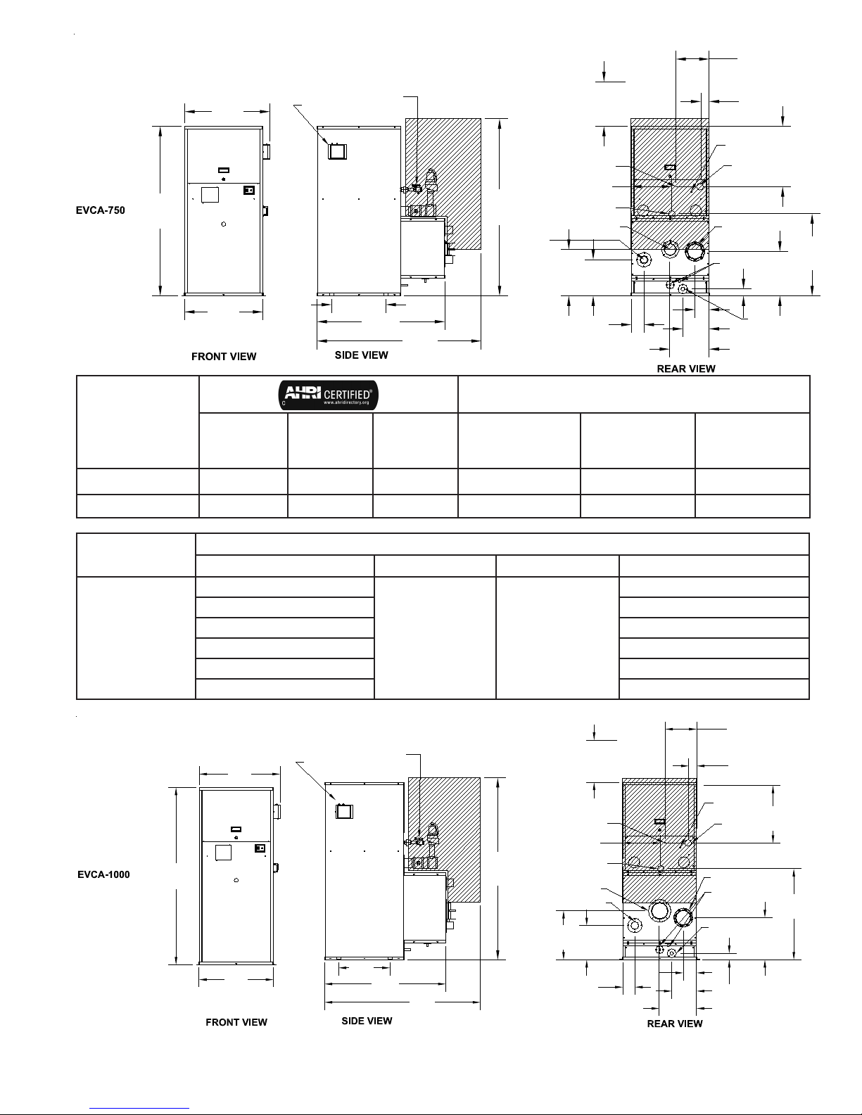
2. See notes concerning Net AHRI Ratings on page 4.
MOUNTED LOW
31.0
[787.4]
60.9
[1547.8]
28.3
[717.6]
WATER CUT-OFF
SHUT-OFF VALVE
19.5
[495.3]
[1169.5]
MANUAL
46.0
56.5
[1435.1]
63.9
[1623.1]
REQUIREMENT
FOR BURNER
REMOVAL
WATER INLET
2.5 NPT
GAS VENT .75
NPT PIPE
14.5
[368.7]
SUPPLY TO
SYSTEM, 2"
VICTAULIC
FLUE OUTLET Ø4
SAF-T-VENT
16.7
13.0
[424.9]
4.6
[116.7]
16.0
[406.4]
[330.9]
5.1
[128.4]
[239.7]
14.2
[360.0]
9.4
CAPACITIES
BOILER MODEL
NUMBER
INPUT
(MBH)
GROSS
OUTPUT
(MBH)
NET AHRI
RATING
2
(MBH)
WATER
VOLUME
(gallons)
DRY WEIGHT
(lbs.)
WET WEIGHT
EVCA-750 750 699 608 16.7 1,401 1,672
12.0
[304.8]
3.0
[76.2]
GAS PILOT
Ø.25 TUBE
GAS SUPPLY
INLET AIR Ø6
GALVANIZED
DUCT
CONDENSATE DRAINS TO BE
PIPED TO AN EXTERNAL TRAP
1 NPT
BOILER DRAIN
1 NPT PIPE
2.5
[63.5]
21.8
[552.9]
16.0
[406.3]
(lbs.)
29.6
[751.1]
EVCA-1000 1,000 939 817 18.4 1,518 1,868
BOILER MODEL
RANGE
750/1000
65.2
SUPPLY (volts/Hz/phase) blower motor (hp) pump motor (hp) Nominal power draw (amps)
120/60/1
208/60/1 9.1
230/60/1 9.0
208/60/3 7.4
230/60/3 7.3
460/60/3 6.3
MANUAL SHUT-OFF
19.5
[495.3]
VALVE
46.0
[1169.5]
[1435.1]
MOUNTED LOW
31.0
[787.4]
[1655.8]
28.3
[717.6]
WATER CUT-OFF
ELECTRICAL
1 1/2 1/4
REQUIREMENT
FOR BURNER
REMOVAL
68.2
[1732.3]
56.5
16.0
GAS VENT .75 NPT
PIPE
14.5
[368.7]
SUPPLY TO SYSTEM,
2" VICTAULIC
FLUE OUTLET Ø6
SAF-T-VENT
WATER INLET
2.5 NPT
18.6
[472.7]
13.0
[330.9]
4.6
[116.7]
14.5
12.0
[304.8]
[406.4]
5.1
[128.4]
14.2
[360.0]
9.4
[239.7]
[76.2]
GAS PILOT
Ø.25 TUBE
GAS SUPPLY
1.5 NPT
INLET AIR Ø6
GALVANIZED DUCT
CONDENSATE DRAINS TO BE
PIPED TO AN EXTERNAL TRAP
BOILER DRAIN
1 NPT PIPE
2.5
[63.5]
3.0
21.8
[552.9]
34.5
[877.4]
16.0
[406.3]
Figure 1a: Dimensions and Capacities EVCA 750 & 1000
5
Page 6
[304.8]
GAS PILOT
Ø.25 TUBE
GAS SUPPLY
1.5 NPT
CONDENSATE DRAINS TO BE
PIPED TO AN EXTERNAL TRAP
BOILER DRAIN
1 NPT PIPE
2.5
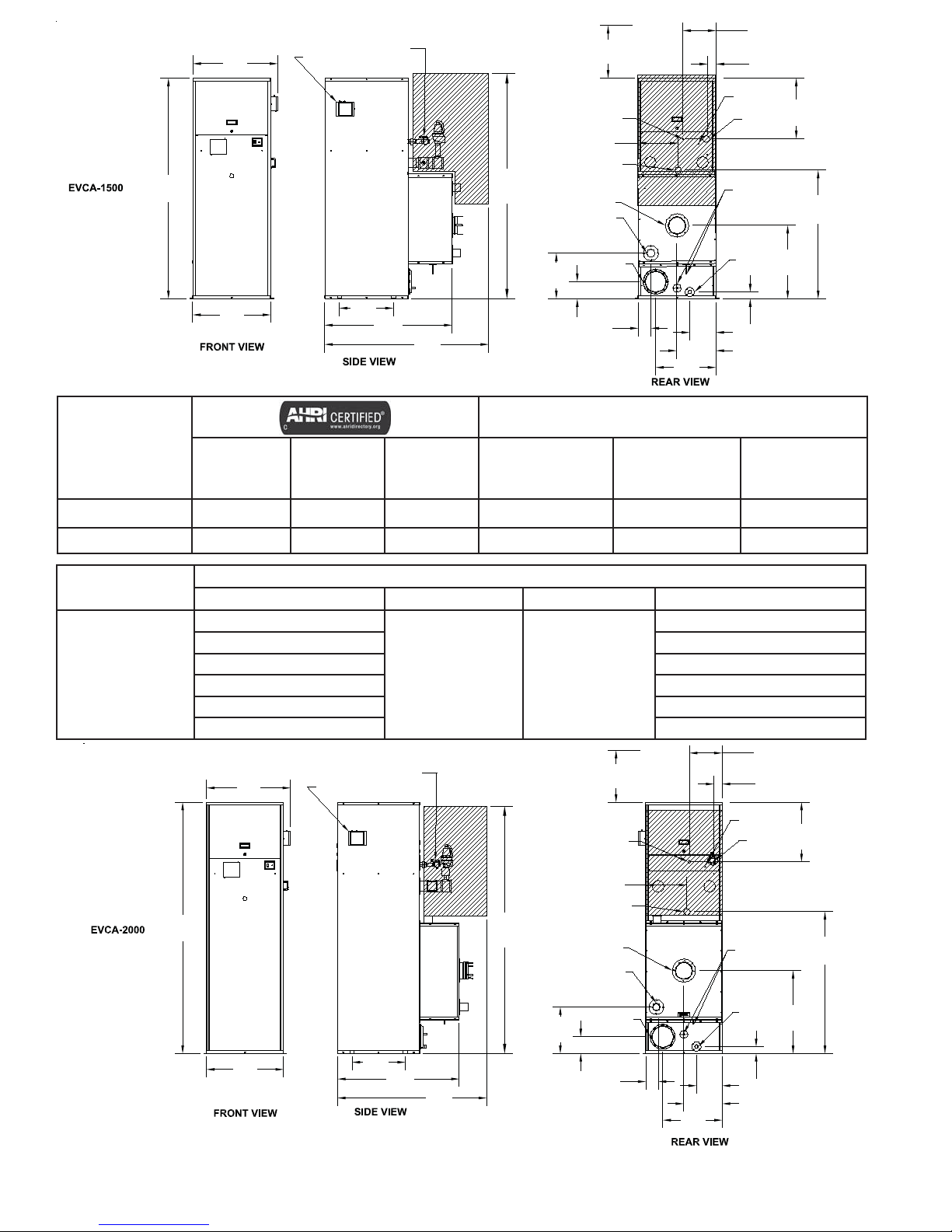
Notes:
1. Piping
removed for
visual clarity.
2. See notes
concerning
Net AHRI
Ratings on
page 4.
82.1
[2085.3]
REQUIREMENT
FOR BURNER
REMOVAL
SUPPLY TO SYSTEM,
FLUE OUTLET Ø6
GALVANIZED DUCT
16.5
[418.8]
6.2
19.0
GAS VENT .75 NPT
PIPE
14.5
[368.7]
2" VICTAULIC
SAF-T-VENT
WATER INLET
2.5 NPT
INLET AIR Ø8
4.6
[116.7]
[157.2]
[482.6]
21.8
[552.5]
14.2
[360.0]
[239.7]
9.4
MANUAL SHUT-OFF
19.5
[495.3]
VALVE
46.0
[1169.5]
56.5
[1435.1]
MOUNTED LOW
31.0
[787.4]
79.1
[2009.1]
28.3
[717.6]
WATER CUT-OFF
CAPACITIES
BOILER MODEL
NUMBER
INPUT
(MBH)
GROSS
OUTPUT
(MBH)
NET AHRI
RATING
2
(MBH)
WATER
VOLUME
(gallons)
DRY WEIGHT
(lbs.)
EVCA-1500 1,500 1,420 1,235 19.8 1,704 1,994
12.0
3.0
[76.2]
21.8
[552.9]
46.4
[1177.8]
26.5
[672.8]
[63.5]
WET WEIGHT
(lbs.)
EVCA-2000 2,000 1,900 1,652 21.2 1,897 2,163
BOILER MODEL
RANGE
1500/2000
SUPPLY (volts/Hz/phase) blower motor (hp) pump motor (hp) Nominal power draw (amps)
120/60/1
208/60/1 11.9
230/60/1 11.8
208/60/3 9.3
230/60/3 9.0
460/60/3 7.2
MANUAL SHUT-OFF
31.0
[787.4]
91.8
[2331.7]
MOUNTED LOW
WATER CUT-OFF
VALVE
1 1/2 3/4
ELECTRICAL
REQUIREMENT
FOR BURNER
REMOVAL
92.8
[2357.1]
31.0
GAS VENT
.75 NPT PIPE
15.1
[384.0]
SUPPLY TO SYSTEM,
2" VICTAULIC
FLUE OUTLET Ø6
SAF-T-VENT
WATER INLET
2.5 NPT
[787.4]
19.3
12.0
[304.8]
3.0
[76.2]
GAS PILOT
Ø.25 TUBE
GAS SUPPLY
1.5 NPT
CONDENSATE DRAINS TO BE
PIPED TO AN EXTERNAL TRAP
21.8
[552.9]
51.9
[1318.5]
28.3
[717.6]
Figure 1b: Dimensions and Capacities EVCA 1500 & 2000
19.5
[495.3]
44.5
[1131.0]
53.0
[1346.2]
BOILER DRAIN
[239.7]
1 NPT PIPE
30.4
[771.7]
9.4
2.5
[63.5]
INLET AIR Ø8
GALVANIZED DUCT
17.1
[433.6]
4.6
[116.7]
6.2
[157.2]
21.8
[552.5]
14.2
[360.0]
6
Page 7
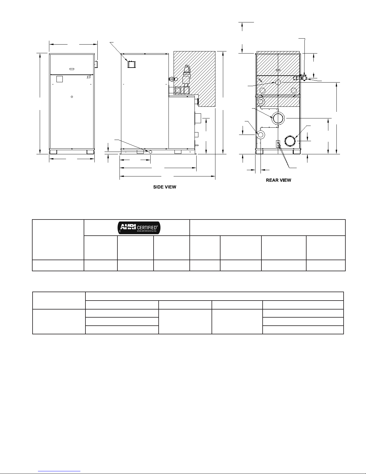
40.8
[1036.3]
MOUNTED LOW
WATER CUT-OFF
REQUIREMENT
FOR BURNER
REMOVAL
SUPPLY TO SYSTEM,
4 Victaulic
MANUAL SHUT-OFF
26.5
[673.1]
VALVE
20.9
[531.8]
GAS SUPPLY
2 NPT
84.5
[2146.3]
Notes:
38.1
[968.2]
FRONT VIEW
BOILER DRAIN
1 NPT PIPE
1.9
26.0
[660.3]
[47.3]
64.5
[1638.1]
80.5
[2044.1]
86.1
FLUE OUTLET Ø8
[2188.1]
SAF-T-VENT
WATER INLET
4 NPT
29.9
[760.1]
16.1
[410.1]
4.4
[112.8]
INLET AIR Ø8
GALVANIZED DUCT
10.9
[275.9]
CONDENSATE DRAINS TO BE
PIPED TO AN EXTERNAL TRAP
1. Piping removed for visual
clarity.
2. See notes concerning Net
AHRI Ratings on page 4.
CAPACITIES
BOILER MODEL
NUMBER
INPUT
(MBH)
GROSS
OUTPUT
(MBH)
NET AHRI
RATING
2
(MBH)
WATER
VOLUME
(gallons)
HEAT
TRANSFER
AREA (sq.ft.)
DRY WEIGHT
(lbs.)
EVCA-3000 3,000 2,910 2,530 53.9 1,426 3,354 3,803
29.9
[760.1]
WET
WEIGHT
(lbs.)
60.2
[1528.3]
BOILER MODEL
SUPPLY (volts/Hz/phase) blower motor (hp) pump motor (hp) Nominal power draw (amps)
208/60/3
EVCA-3000
230/60/3 13.9
460/60/3 7.0
Figure 1c: Dimensions and Capacities EVCA 3000
ELECTRICAL
14.6
2 2
7
Page 8

I. Pre-Installation
WARNING
Carefully read all instructions before installing
boiler. Failure to follow all instructions in proper
order can cause personal injury or death.
A. Installation must conform to the requirements of
the authority having jurisdiction. In the absence of
such requirements, installation must conform to the
National Fuel Gas Code, NFPA 54/ANSI Z223.1, and/
or CAN/CGA B149 Installation Codes. Where required
by the authority having jurisdiction, the installation
must conform to the Standard for Controls and Safety
Devices for Automatically Fired Boilers, ANSI/ASME
CSD-1.
B. e boiler is not design certied for installation on
combustible ooring. e boiler must not be installed
on carpeting.
C. Provide clearance between boiler jacket and combustible
material in accordance with local re ordinance. Refer
to page 4 of this manual for minimum listed clearance
from combustible material.
D. Install on level oor. For basement installation provide
concrete base if oor is not perfectly level or if water
may be encountered on oor around boiler. Floor
must be able to support weight of boiler, water and all
additional system components.
E. Protect gas ignition system components from water
(dripping, spraying, rain, etc.) during boiler operation
and service (circulator replacement, condensate trap
service, control replacement, etc.).
1. Determine volume of space (boiler room). Rooms
communicating directly with space (through
openings not furnished with doors) are considered
part of space.
Volume [³] = Length [] x Width [] x Height []
2. Determine Total Input of all appliances in space.
Round result to nearest 1,000 Btu per hour (Btuh).
3. Determine type of space. Divide Volume by Total
Input.
a. If result is greater than or equal to 50 ³ per 1,000
Btuh, space is considered an unconned space.
b. If result is less than 50 ³ per 1,000 Btuh, space is
considered a conned space.
4. Determine building type. A building of unusually
tight construction has the following characteristics:
a. Walls and ceiling exposed to outside atmosphere
have a continuous water vapor retarder with a
rating of 1 perm or less with openings gasketed
and sealed, and;
b. Weather-stripping has been added on openable
windows and doors, and;
c. Caulking or sealants applied in joints around
window and door frames, between sole plates and
oors, between wall-ceiling joints, between wall
panels, at plumbing and electrical penetrations,
and at other openings.
5. For boiler located in an unconned space in a
building of other than unusually tight construction,
adequate combustion and ventilation air is normally
provided by fresh air inltration through cracks
around windows and doors.
NOTICE
F. Provide combustion and ventilation air in accordance
with applicable provisions of local building codes or:
USA - National Fuel Gas Code, NFPA 54/ANSI Z223.1,
Section 5.3, Air for Combustion and Ventilation;
Canada - Natural Gas Installation Code, CAN/CGA
- B149.1, or Propane Installation Code, CAN/CGA
- B.149.2, Part 5, Venting Systems and Air Supply for
Appliances.
WARNING
Adequate combustion and ventilation air must
be provided to assure proper combustion.
e following guideline is based on the National Fuel
Gas Code, NFPA 54/ANSI Z223.1.
Boilers operated with sealed combustion are
exempt from needing provisions for combustion
air from the room, provided air intake piping is
installed per code and the instructions in this
manual.
6. For boiler located within unconned space in
building of unusually tight construction or within
conned space, provide outdoor air through two
permanent openings which communicate directly or by
duct with the outdoors or spaces (crawl or attic) freely
communicating with the outdoors. Locate one opening
within 12 inches of top of space. Locate remaining
opening within 12 inches of bottom of space. Minimum
dimension of air opening is 3 inches. Size each opening
per the following:
8
Page 9
a. Direct communication with outdoors. Minimum
free area of 1 square inch per 4,000 Btu per hour
input of all equipment in space.
b. Vertical ducts. Minimum free area of 1 square
inch per 4,000 Btu per hour input of all
equipment in space. Duct cross-sectional area
shall be same as opening free area.
c. Horizontal ducts. Minimum free area of 1
square inch per 2,000 Btu per hour input of all
equipment in space. Duct cross-sectional area
shall be same as opening free area.
Alternate method for boiler located within conned
space. Use indoor air if two permanent openings
communicate directly with additional space(s) of
sucient volume such that combined volume of all
spaces meet criteria for unconned space. Size each
opening for minimum free area of 1 square inch per
1,000 Btu per hour input of all equipment in spaces,
but not less than 100 square inches.
7. Ventilation Duct Louvers and Grilles. Equip outside
openings with louvers to prevent entrance of rain
and snow, and screens to prevent entrance of insects
and rodents. Louvers and grilles must be xed in
open position or interlocked with equipment to
open automatically before burner operation. Screens
must not be smaller than ¼ inch mesh.
Consider the blocking eect of louvers, grilles and
screens when calculating the opening size to provide
the required free area. If free area of louver or grille
is not known, assume wood louvers have 20-25
percent free area and metal louvers and grilles have
60-75 percent free area.
DANGER
Do not install boiler where gasoline or other
ammable vapors or liquids, or sources
of hydrocarbons (i.e. bleaches, cleaners,
chemicals, sprays, paint removers, fabric
softeners, etc.) are used or stored.
NOTICE
Due to the low water content of the boiler,
incorrect sizing of the boiler with regard to the
heating system load will result in excessive
boiler cycling and accelerated component
failure. Thermal Solutions DOES NOT warrant
failures caused by incorrectly sized boiler
applications. DO NOT oversize the boiler to
the system. Modular boilers greatly reduce the
likelihood of boiler oversizing.
II. Unpacking the Boiler
NOTICE
Boiler crate is equipped with a tip & tell label.
If label indicates boiler has been tipped over
during shipping, remove crate and inspect
before trucker leaves.
CAUTION
Do not drop boiler. Do not bump boiler jacket
against oor.
A. Move boiler to approximate installed position.
B. Remove all crate fasteners.
C. Open outside container and remove all inside protective
spacers and bracing.
D. Remove all boiler hold-down fasteners.
WARNING
Installation of this boiler should be undertaken
only by trained and skilled personnel from a
qualied service agency.
E. Remove unit from shipping skid (if provided.)
1. Tilt the boiler to one side and slide a small roller
under the raised base.
2. Tilt the boiler to the other side and slide another
roller under the base.
3. Place a larger pipe roller on oor behind the skid.
4. Roll the boiler forward or backward o the skid and
onto the pipe roller.
F. Move boiler to its permanent location.
WARNING
Boiler air vent is shipped loose for EVCA 750-
2000. Refer to water piping and trim section prior
to lling the boiler with water.
9
Page 10

III. Installation
A. VENTING
WARNING
Improper venting may result in property damage
and the release of ue gasses which contain
deadly carbon monoxide (CO) into the building,
which can cause severe personal injury and/or
death.
1. Venting Requirements
In order to properly vent this boiler, the installer
must select and install a vent system that meets all
requirements specied in this section (VENTING) as
well as following the instructions provided by the vent
system manufacturer.
a. e vent system shall be designed and constructed in
accordance with the National Fuel Gas Code/NFPA
54 ANSI Z223.1 and applicable local building codes to
develop a positive ow adequate to convey ue or vent
gasses to the outdoors.
b. If this boiler is being installed in Massachusetts, follow
the Massachusetts Code instructions printed later in this
section.
c. Consult the vent pipe manufacturer’s instructions for
vent system assembly and system specic installation
requirements.
g. Vent pipe system must be adequately supported at
intervals no less than ve (5) feet apart. e completed
vent system must be rigid and able to withstand impacts
without collapse.
h. is boiler’s venting is Category IV (positive vent
pressure, ue condensing), with regards to National Fuel
Gas Code/NFPA 54 ANSI Z223.1.
i. Vent pipe system must be fully sealed.
j. Atmospheric venting is prohibited.
k. For multiple boiler installations, each boiler must have
its own independent vent system. Common venting
with additional or any other appliances is prohibited.
WARNING
Do not use vent dampers or barometric dampers
with this boiler.
l. Direct vent applications: For direct vent (ducted
combustion air) installations, the maximum vent length
is 50 equivalent feet. e vent length is equal to the total
length of straight pipe plus the equivalent length of vent
ttings.
m. Non-direct vent applications: For non-direct vent
installations (those without ducted combustion air),
design the vent system so that the pressure measured at
the outlet of the boiler is between 0”w.c. and 0.3”w.c. at
high re.
WARNING
Vent pipe system must be made of materials
approved for use with condensing ue gasses.
d. Vent pipe system shall be acceptable for use with boiler
fuel type.
e. Vent pipe system shall be compatible either by directly
connecting, or by use of an adapter, to the boiler vent
connection.
i. is boiler is shipped with an AL 29-4C® Heat-Fab
Saf-T-Vent connection.
ii. Alteration of the boiler vent connection is
prohibited.
f. Do not reduce the diameter of the vent pipe. e vent
pipe must not be smaller than the vent connector on the
boiler.
n. If any point of the vent pipe system is higher than the
boiler ue collar, the vent system must have adequate
condensate drain loop(s) to prevent condensate from
running back into the boiler.
o. It is permissible to run vent pipe through a vertical
or horizontal chase provided minimum clearances to
combustible materials are maintained.
p. e minimum clearance to combustible material
is six (6) inches, unless otherwise specied by vent
manufacturer.
q. Horizontal vent pipe must slope no less than one (1)
inch in four (4) feet of run. For sidewall venting, slope
pipe toward vent termination if possible.
r. e vent termination location is restricted as follows:
i. Minimum twelve (12) inches above grade plus
normally expected snow accumulation or seven (7)
feet above grade if located adjacent to public walkways.
DO NOT INSTALL over public walkway where local
experience indicates condensation or vapor from the
boiler creates a nuisance or hazard.
10
Page 11

ii. Minimum three (3) feet above any forced air inlet
located within ten (10) feet of the vent termination.
iii. Minimum four (4) feet below, four (4) feet
horizontally or one (1) foot above any door, window or
gravity air inlet.
iv. Minimum four (4) feet horizontally from electric
meters, gas meters, regulators and relief valves. is
distance may be reduced if equipment is protected from
damage due to condensation or vapor by enclosure,
overhangs, etc.
v. Minimum twelve (12) inches from corners of
building.
3. IMPORTANT
e Commonwealth of Massachusetts requires
compliance with regulation 248 CMR 4.00 and 5.00 for
installation of side-wall vented gas appliances as follows:
(a) For all side wall horizontally vented gas fueled
equipment installed in every dwelling, building or
structure used in whole or in part for residential
purposes, including those owned or operated by the
Commonwealth and where the side wall exhaust
vent termination is less than seven (7) feet above
nished grade in the area of the venting, including
but not limited to decks and porches, the following
requirements shall be satised:
s. Use appropriately designed thimbles when passing
through combustible walls or roofs.
t. Install re-stops where vent passes through oors,
ceilings or framed walls. e re-stop must close the
opening between the vent pipe and the structure.
u. Enclose vent passing through occupied or unoccupied
spaces above the boiler with materials having a re
resistance rating at least equal to the rating of the
adjoining oor or ceiling. Maintain minimum clearance
to combustible materials.
v. Locate vent terminal above combustion air intake
terminal (if used) and no closer than one (1) foot
horizontally.
w. Vertical venting requires ashing and a storm collar to
prevent moisture from entering the structure.
x. Vertical vent termination must be at least two (2)
feet plus the expected snow accumulation above roof
penetration height.
2. General Guidelines
a. is boiler has been certied with AL29-4C® venting.
Select a vent material that is approved for use with
condensing ue gasses.
b. Install vent system before installing air intake, water, gas
or electrical connections.
c. For instances where the vent system manufacturer’s
instructions do not make a specication, refer to the
below points.
1. INSTALLATION OF CARBON MONOXIDE
DETECTORS. At the time of installation of the side wall
horizontal vented gas fueled equipment, the installing
plumber or gastter shall observe that a hard wired
carbon monoxide detector with an alarm and battery
back-up is installed on the oor level where the gas
equipment is to be installed. In addition, the installing
plumber or gastter shall observe that a battery
operated or hard wired carbon monoxide detector
with an alarm is installed on each additional level of
the dwelling, building or structure served by the side
wall horizontal vented gas fueled equipment. It shall
be the responsibility of the property owner to secure
the services of qualied licensed professionals for the
installation of hard wired carbon monoxide detectors.
a. In the event that the side wall horizontally vented
gas fueled equipment is installed in a crawl space or an
attic, the hard wired carbon monoxide detector with
alarm and battery back-up may be installed on the next
adjacent oor level.
b. In the event that the requirements of this
subdivision can not be met at the time of completion of
installation, the owner shall have a period of thirty (30)
days to comply with the above requirements; provided,
however, that during said thirty (30) day period, a
battery operated carbon monoxide detector with an
alarm shall be installed.
2. APPROVED CARBON MONOXIDE DETECTORS.
Each carbon monoxide detector as required in
accordance with the above provisions shall comply
with NFPA 720 and be ANSI/UL 2034 listed and IAS
certied.
i. Make sure pipe and ttings are clean by swabbing
with alcohol. Use Dow Corning 736 or 732 RTV,
Polybar #500 RTV or Sil-bond 4500 or 6500 to seal vent
pipe.
ii. Refer to the appropriate drawings in this section
of this manual to determine common acceptable
congurations of venting system.
3. SIGNAGE. A metal or plastic identication plate shall be
permanently mounted to the exterior of the building at a
minimum height of eight (8) feet above grade directly in
line with the exhaust vent terminal for the horizontally
vented gas fueled heating appliance or equipment. e
sign shall read, in print size no less than one-half (1/2)
inch in size, “GAS VENT DIRECTLY BELOW. KEEP
CLEAR OF ALL OBSTRUCTIONS”.
11
Page 12

4. INSPECTION. e state or local gas inspector of the
side wall horizontally vented gas fueled equipment shall
not approve the installation unless, upon inspection,
the inspector observes carbon monoxide detectors and
signage installed in accordance with the provisions of
248 CMR 5.08(2)(a)1 through 4.
B. EXEMPTIONS: e following equipment is exempt
from 248 CMR 5.08(2)(a)1 through 4:
1. e equipment listed in Chapter 10 entitled
“Equipment Not Required To Be Vented” in the
most current edition of NFPA 54 as adopted by the
Board; and
2. Product Approved side wall horizontally vented
gas fueled equipment installed in a room or
structure separate from the dwelling, building or
structure used in whole or in part for residential
purposes.
C. MANUFACTURER REQUIREMENTS - GAS
EQUIPMENT VENTING SYSTEM PROVIDED.
When the manufacturer of Product Approved side
wall horizontally vented gas equipment provides a
venting system design or venting system components
with the equipment, the instructions provided by the
manufacturer for installation of the equipment and the
venting system shall include:
1. Detailed instructions for the installation of
the venting system design or the venting system
components; and
2. A complete parts list for the venting system
design or venting system.
D. MANUFACTURER REQUIREMENTS - GAS
EQUIPMENT VENTING SYSTEM NOT PROVIDED.
When the manufacturer of a Product Approved side
wall horizontally vented gas fueled equipment does
not provide the parts for venting the ue gases, but
identies “special venting systems”, the following
requirements shall be satised by the manufacturer:
1. e referenced “special venting system”
instructions shall be included with the appliance or
equipment installation instructions; and
2. e “special venting systems” shall be Product
Approved by the Board, and the instructions for
that system shall include a parts list and detailed
installation instructions.
E. A copy of all installation instructions for all Product
Approved side wall horizontally vented gas fueled
equipment, all venting instructions, all parts lists
for venting instructions, and/or all venting design
instructions shall remain with the appliance or
equipment at the completion of the installation.
12
Page 13
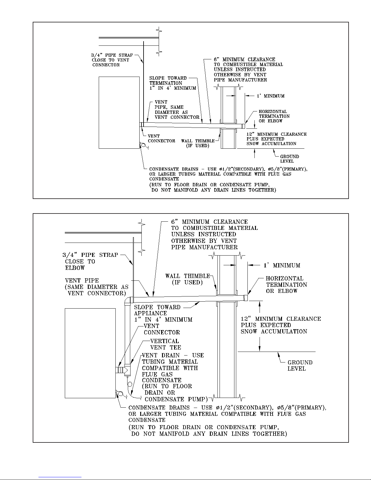
Figure 2: Typical Sidewall Pressurized Venting
Figure 3: Typical Sidewall Pressurized Venting (Optional)
13
Page 14
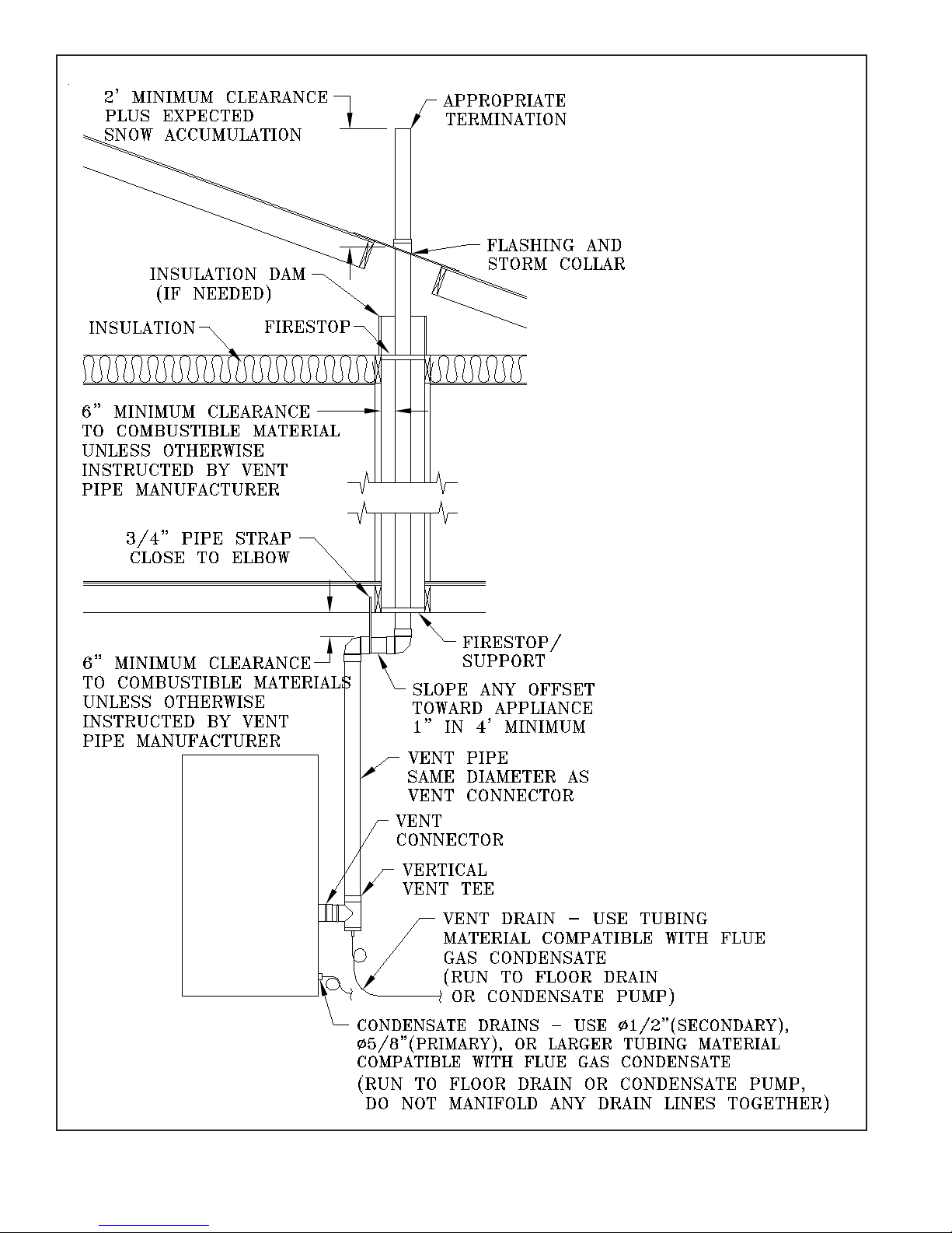
Figure 4: Typical Vertical Pressurized Venting
14
Page 15

B. COMBUSTION AIR - See Figures 5 and 6
1. e boiler may be operated with inside or outside
air.
2. Refer to combustion air piping drawings in this
section of this manual for proper outside air
installation details.
3. Combustion air conduit can be galvanized smoke
pipe, PVC, CPVC, or exible aluminum conduit.
4. e maximum air inlet length is y (50) equivalent
feet. Air inlet length is equal to the total length of
straight pipe plus the equivalent length of ttings.
Consult conduit manufacturer for equivalent length
of ttings and pipe.
5. Consult intake pipe manufacturer's instructions
for proper method of sealing vent pipe sections
and ttings. Do not use other adhesives or sealants
except as expressly permitted by the vent pipe
manufacturer's instructions.
WARNING
Do not reduce size of air intake pipe.
Read, understand and follow combustion air
instruction restrictions contained in the PreInstallation instructions of this manual.
WARNING
Do not locate air intake where petroleum
distillates, CFCs, detergents, volatile vapors
or any other chemicals are present. Severe
boiler corrosion and failure will result.
Thermal Solutions does not warrant failures
caused by contaminated air.
Do not locate air intake termination where
natural convection or wind conditions may
cause the boiler exhaust gases to be drawn
into the air intake.
6. Air intake termination must be located at least
twelve (12) inches above grade plus the expected
snow accumulation.
7. Boiler may be installed with vertical venting and
sidewall combustion air inlet or visa versa.
8. e air intake pipe must be adequately supported
with straps or supports no less than ve (5) feet
apart. e completed air intake pipe system must be
rigid and able to withstand impacts without collapse.
CAUTION
Dirty, contaminated or dusty air used for
combustion will decrease the useful life of
the boiler air lter. Use outside air if inside
air quality is questionable. Use outside air if
the boiler is installed in manufacturing plants,
laundries, dry cleaners or other locations with
heavy particulates in the air.
15
Page 16
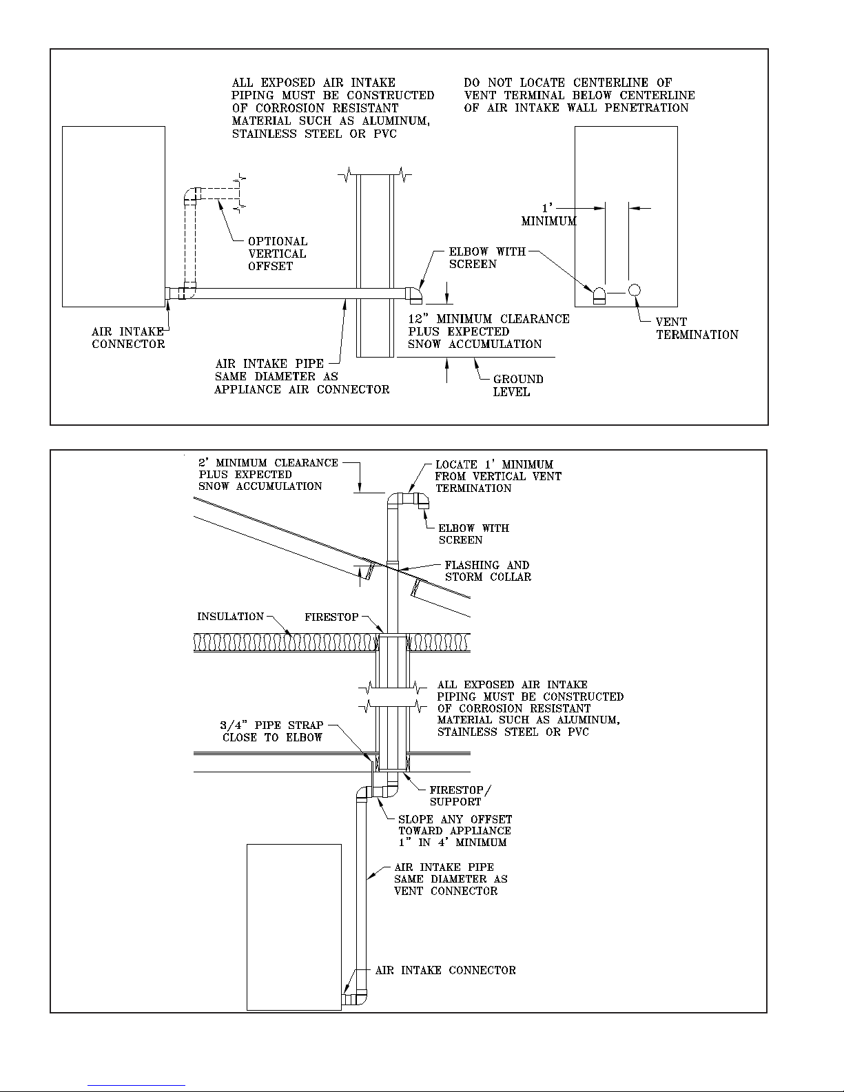
Figure 5: Horizontal Air Intake Piping
Figure 6: Vertical Air Intake Piping
16
Page 17
C. WATER TREATMENT
e quality of water used in the heating system is essential
for the successful operation and longevity of the system
components. A successful water treatment plan will help
to maintain eciency, reduce the regularity of repair and/
or replacement, and extend the working life of the boiler
and other system equipment. If le untreated, poor water
quality could cause a number of problems including, but not
limited to, oxidation, scaling, corrosion, and fouling. See
Table 1A for examples of typical chemical agents found in
untreated water along with their potential eects.
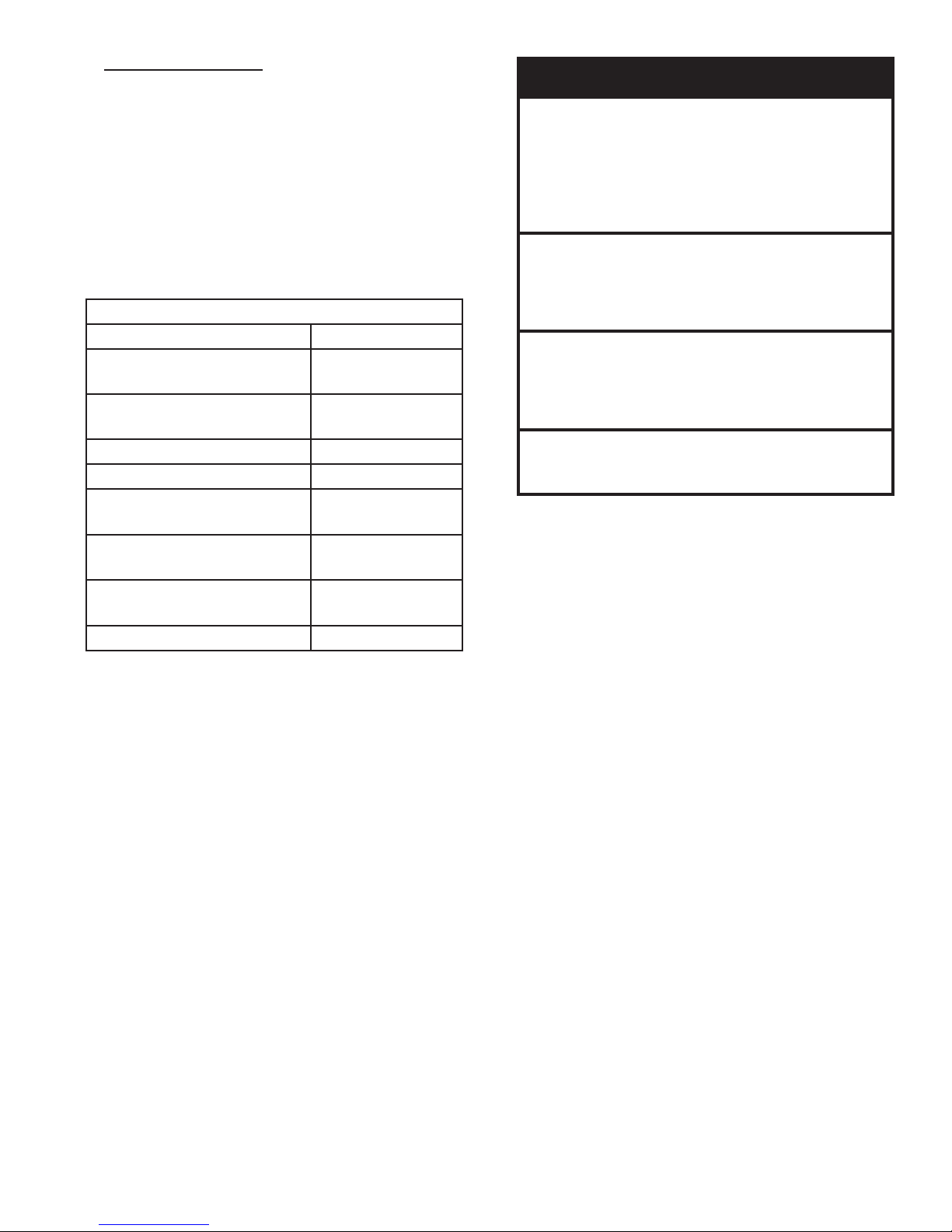
Table 1A: Chemical Agents and Effects
Compound Effect
Calcium Carbonate
Soft Scale
(CaCO3)
Calcium Bicarbonate
Soft Scale, CO
2
(CaHCO3)
Calcium Sulphate (CaSO4) Hard Scale
Calcium Chloride (CaCl2) Corrosion
Magnesium Carbonate
Soft Scale
(MgCO3)
Magnesium Bicarbonate
Corrosion, Scale
(MgHCO3)
Magnesium Sulphate
Corrosion
(MgSO4)
Silicon Dioxide (SiO2) Hard Scale
CAUTION
The water shall have a maximum water hardness
of 8.5 grains or 150 ppm. The recommended
pH range is 8.8 to 9.2. However, other aspects
of water quality can affect boiler operation and
longevity. A qualied water treatment expert
should be consulted to develop a complete
water treatment plan.
Oxygen contamination of boiler water will cause
corrosion of iron and steel boiler components,
and can lead to boiler failure. Thermal Solutions
Standard Warranty does not cover problems
caused by oxygen contamination of boiler water.
Proper water treatment and boiler maintenance
is required to avoid scale build-up on the inside
of the boiler. Thermal Solutions Standard
Warranty does not cover problems caused by
scale build-up.
When using Glycol products, all Glycol
manufacturers' requirements, including rust
inhibitors, must be adhered. Max 50% Glycol.
Since the condition of water varies from location to location,
it is impossible to prescribe a one-size-ts-all treatment plan
for the system water. In order to develop an eective water
treatment plan, it will be necessary to gain knowledge of the
impurities dissolved in the water. Once all the impurities
are identied, the proper treatment plan can be established.
erefore, it will be essential to obtain the expertise of
a qualied industrial water treatment professional for
establishing a treatment plan.
In addition, a periodic testing/sampling plan should be
developed. e intent of the plan should be to: (1) ensure the
protection of the boiler and system equipment, (2) prevent
an unforeseen system failure, (3) provide information for
use in addressing the water quality, and (4) to conrm the
proper concentration of chemicals in use.
17
Page 18
D. WATER PIPING AND TRIM
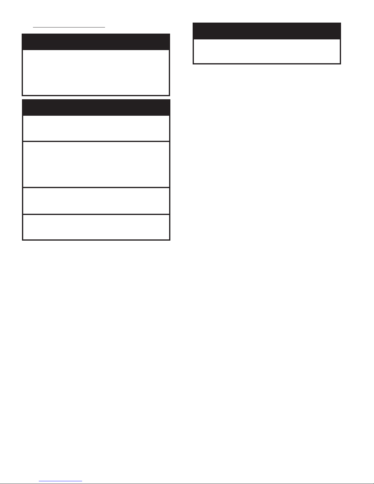
CAUTION
WARNING
For EVCA 750-2000, the boiler air vent is shipped
loose. Prior to connecting system piping to
boiler, or lling the boiler with water, remove
protective cap from the tagged elbow at the top
of the loop piping. Install supplied air vent to
boiler elbow using teon tape.
CAUTION
Failure to properly pipe boiler may result in
improper operation and damage to boiler or
structure.
All piping, either new or existing, must be
cleaned with a tri sodium (TSP) solution to
remove mill scale and oils from the system.
Failure to do so could result in premature failure
of the heat exchanger (not covered by Thermal
Solutions warranty.
On an existing or retrot system, a lter or
strainer must be installed on the system return
prior to the boilers.
When using Glycol products, all Glycol
manufacturers' requirements, including rust
inhibitors, must be adhered.
1. Design and install boiler and system piping to
prevent oxygen contamination of boiler water
and frequent water additions.
a. ere are many possible causes of oxygen
contamination such as:
i. Addition of excessive make-up water
as a result of system leaks.
ii. Absorption through open tanks and ttings.
iii. Oxygen permeable materials in the
distribution system.
b. In order to insure long product life, oxygen
sources must be eliminated. is can be
accomplished by taking the following measures:
i. Repairing system leaks to eliminate the need
for addition of make-up water.
ii. Eliminating and/or repairing ttings which
allow oxygen absorption.
iii. Using of non-permeable materials in the
distribution system.
iv. Isolating the boiler from the system water by
installing a heat exchanger.
v. Using properly designed and operating air
elimination devices in water piping.
Support weight of system piping adequately.
Boiler loop piping is not designed to support
system piping weight.
2. Connect system supply and return piping to boiler.
a. Refer to Figure 8.
b. Consult I=B=R Installation and Piping Guides.
c. Maintain ½" minimum distance between water
piping and combustible material.
d. Consult ermal Solutions for unusual system
requirements.
3. Remove protective cap from boiler drain line located
in the rear of the boiler (EVCA-750 through 2000)
or the right side of the boiler (EVCA-3000).
4. For EVCA-3000, install a 10" minimum or longer 1"
diameter nipple into hole in right side of base and
thread into drain elbow underneath the boiler.
5. Install drain valve in the boiler drain line at bottom
rear or right side of the boiler.
6. If this boiler is used in connection with refrigeration
systems, the boiler must be installed so that the
chilled medium is piped in parallel with the boiler
using appropriate valves to prevent the chilled
medium from entering the boiler. Also consult
I=B=R Installation and Piping Guides. If this boiler
is connected to heating coils located in air handling
units where they may be exposed to refrigerated air,
the boiler piping must be equipped with ow control
valves to prevent gravity circulation of boiler water
during operation of the cooling system.
7. Install optional low water cut-o in system piping
above the boiler, if not shipped with boiler. On
EVCA-750 through -2000 boilers, a low water cuto may be installed on the boiler at the factory as
an option. A factory-mounted low water cut-o is
standard on all EVCA-3000 boilers.
8. Install an air eliminating device to remove air from
the system.
18
Page 19
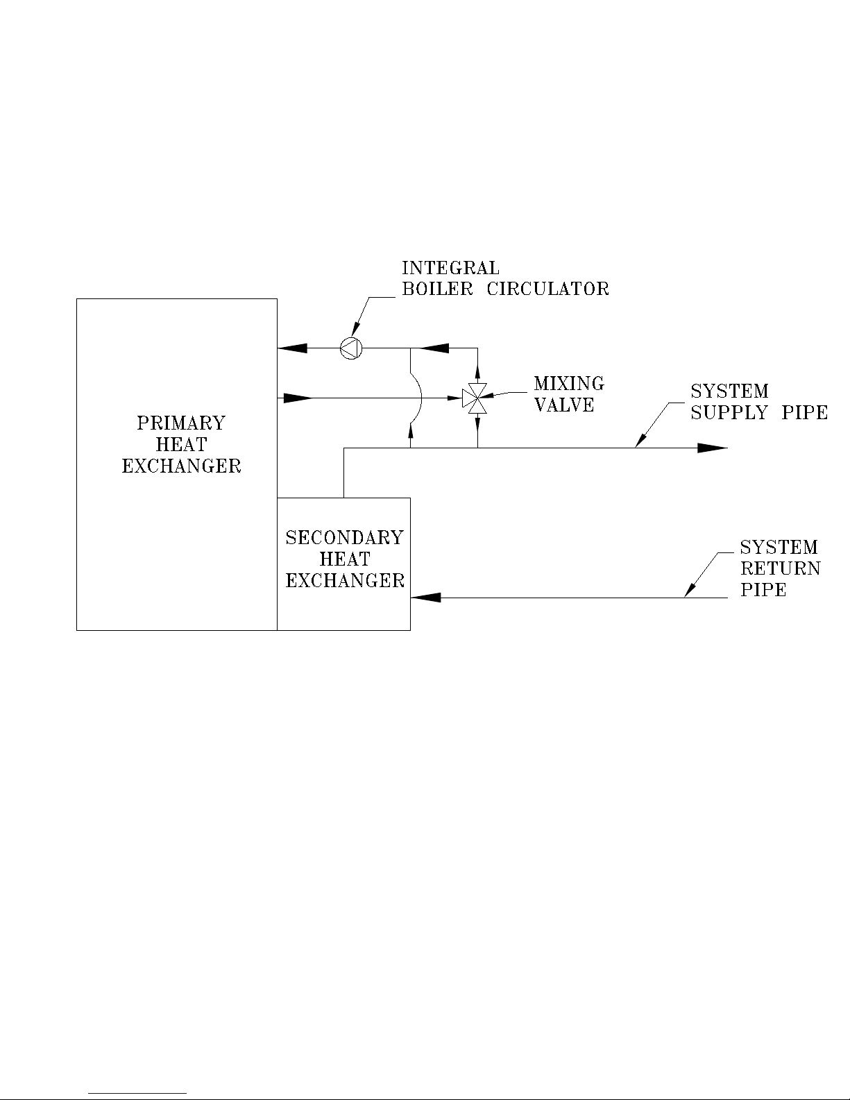
Figure 8: Schematic Boiler Piping
19
Page 20
WARNING
Failure to operate the unit with the proper water
ow rate can lead to appliance failure. Always
verify proper water ow switch operation so that
the unit stops operating if improper water ow is
present.
Safety relief valve discharge piping must be
piped such that the potential of severe burns
is eliminated. DO NOT pipe in any area where
freezing could occur. DO NOT install any shutoff valves, plugs or caps. Consult Local Codes
for proper discharge piping arrangement.
If a high head system pump is installed, ensure
that the boiler relief valve and system piping are
capable of operating properly at the combined
pressure of the system ll pressure plus the
pump static head pressure.
Do not install valves, plugs or caps in safety
relief valve piping.
Safety relief valve piping must be terminated
such that in the event the safety relief valve
opens, the discharge will not cause personal
injury or damage.
Do not operate the boiler with ow rates in
excess of the maximum ow rates listed in Table
1B Tube erosion and pitting will occur. Thermal
Solutions Standard Warranty does not cover
problems caused by excessive water ow rates.
supplier or local plumbing inspector on how best to
control this situation.
12. A pressure relief valve is supplied with each boiler.
No valve is to be placed between the relief valve and
appliance.
a. Pipe the safety relief discharge to a suitable place
for disposal when relief occurs.
b. Do not install reducing couplings or other
restrictive devices in the safety relief discharge
line.
c. e safety relief discharge line must allow for
complete drainage of both the valve and line.
13. If the relief valve discharges periodically, this may be
due to thermal expansion in a closed water supply
system. Contact the water supplier or local plumbing
inspector on how to correct this situation. DO NOT
PLUG THE RELIEF VALVE.
9. Refer to Table 1B for pressure drop, ow rates, and
temperature rise (ΔTs).
10. e factory supplied circulator is not intended to
replace the boiler supply circulator or the system
supply circulator. It provides a constant ow to the
primary heat exchanger.
11. If the boiler is installed in a closed water supply
system, such as one having a back ow preventer in
the cold water supply line, means shall be provided
to control thermal expansion. Contact the water
Table 1B- EVCA BOILER FLOW AND PRESSURE DROP
BOILER
MODEL
(Ft. hd)
EVCA-750 32.4 70 17.8 47 11.6 35 8.3 28 6.3 23 5.0 20
EVCA-1000 36.9 94 20.9 63 13.9 47 10.2 38 7.9 31 6.4 27
EVCA-1500 53.7 142 27.3 95 16.9 71 11.7 57 8.6 47 6.7 41
EVCA-2000 67.8 190 36.0 127 23.0 95 16.2 76 12.2 63 9.6 54
EVCA-3000 29.2 291 15.2 194 9.6 146 6.7 116 5.0 97 3.9 83
Note: * Indicates maximum allowable ow rate.
*20°F ∆T 30°F ∆T 40°F ∆T 50°F ∆T 60°F ∆T 70°F ∆T
DP
GPM
DP
(Ft. hd)
GPM
DP
(Ft. hd)
GPM
DP
(Ft. hd)
GPM
DP
(Ft. hd)
GPM
DP
(Ft. hd)
GPM
20
Page 21
E. GAS PIPING
WARNING
Failure to properly pipe gas supply to boiler may
result in improper operation and damage to the
boiler or structure. Always assure gas piping is
absolutely leak free and of the proper size and
type for the connected load.
An additional gas pressure regulator may be
needed. Consult gas supplier.
1. Size gas piping. Design system to provide adequate
gas supply to boiler. Consider these factors.
a. Allowable pressure drop from point of delivery
to boiler. Refer to Table 2 for minimum and
maximum boiler gas train inlet pressure. If gas
supply pressure is higher than maximum as listed
in Table 2, an additional eld supplied pressure
regulator will be required.
be located as far away from the boiler as possible to
prevent nuisance shutdowns.
a. e minimum and maximum inlet gas pressure
must not exceed the value specied in Table 2.
3. Install eld supplied sediment trap, ground-joint
union and manual non-displaceable shut-o valve
upstream of factory supplied shut-o valve outside
the boiler jacket. Use methods and materials in
accordance with Local Codes and requirements of
gas supplier. In absence of such requirements, follow
National Fuel Gas Code, NFPA 54/ANSI Z223.1
and/or CAN/CGA B149 Installation Codes.
4. Use thread joint compound resistant to the action of
liqueed petroleum gas.
WARNING
Failure use proper thread compounds on all gas
connectors may result in leaks of ammable gas.
TABLE 2 - BOILER GAS TRAIN
INLET PRESSURE
BOILER
MODEL
MIN ("w.c.) MAX (psig)
EVCA-750 7.0 5
EVCA-1000 7.0 5
EVCA-1500 7.0 5
EVCA-2000 9.0 5
EVCA-3000 6.0 5
b. If a lower minimum gas pressure is needed,
the low gas pressure build can be used. e
minimum gas pressure on all of the low gas
pressure builds is 4.0 in. w.c. Consult factory if
this option is desired. is option is not available
on the EVCA-3000.
c. Maximum gas demand. Table 6 lists boiler input
rate. Also consider existing and expected future
gas utilization equipment (i.e., water heater,
cooking equipment).
d. Length of piping and number of ttings. Refer
to Table 3 for maximum capacity of schedule
40 pipe. Table 5 lists equivalent pipe length for
standard ttings.
i. Given the specic gravity of gas at your
location, a correction factor can be found on
Table 4 and multiplied by the "Capacity in
Cubic Feet of gas Per Hour" on Table 3.
ii. For gas piping material other than schedule
40 pipe, refer to the National Fuel Gas Code,
NFPA 54/ANSI Z223.1 and/or CAN/CGA
B149 Installation codes.
MODULATION
5. All above ground gas piping upstream from eld
supplied manual gas valve must be electrically
continuous and bonded to a grounding electrode.
Do not use gas piping as grounding electrode. Refer
to National Electrical Code, ANSI/NFPA 70 and /or
CSA C22.1 Electrical Codes.
WARNING
Gas supply to boiler and system must be
absolutely shut off prior to installing or servicing
boiler gas piping.
WARNING
Use an additional gas pressure regulator where
the gas pressure is greater than 5 psig. Using
one additional regulator for multiple boilers
may result in unsafe boiler operation. The
additional regulator must be able to properly
regulate gas pressure ow at the lowest input of
a single boiler. If the regulator cannot do this,
two or more additional regulators are required.
Consult regulator manufacturer's instructions for
minimum gas ow rate.
NOTICE
The EVCA-3000 is shipped with the gas line
regulator in the downward position. During
installation loosen the union behind the regulator
and rotate gas inlet to horizontal orientation.
Remove cap and reattach 1/4" regulator tubing to
regulator.
2. If step down regulator is required, it must be used in
conjunction with the factory supplied regulator and
21
Page 22
6. Pressure test. e boiler and its gas connection must
be leak tested before placing boiler in operation.
a. Protect boiler gas control valve. For all testing
over ½ psig, boiler and its individual shuto
valve must be disconnected from gas supply
piping. For testing at ½ psig or less, isolate
boiler from gas supply piping by closing the
boiler's individual manual shuto valve.
b.. Locate leaks using approved combustible
gas detector, soap and water, or similar
nonammable solution.
Do not use matches, candles, open ames or
other ignition source to check for leaks.
DANGER
TABLE 3: MAXIMUM GAS CAPACITY OF SCHEDULE 40 PIPE.
(Based on Gas Pressure less than 2 psi, pressure drop of 0.3 in w.c. and 0.6 specic gravity.)
Pipe Length in
Pipe Size (in.)
Equivalent Feet
3/4 1 1-1/4 1-1/2 2 2-1/2 3 4
Capacity in Cubic Feet of Gas Per Hour
10 273 514 1060 1580 3050 4860 8580 17500
20 188 353 726 1090 2090 3340 5900 12000
30 151 284 583 873 1680 2680 4740 9660
40 129 243 499 747 1440 2290 4050 8270
50 114 215 442 662 1280 2030 3590 7330
60 104 195 400 600 1160 1840 3260 6640
70 95 179 368 552 1060 1690 3000 6110
80 89 167 343 514 989 1580 2790 5680
90 83 157 322 482 928 1480 2610 5330
100 79 148 304 455 877 1400 2470 5040
125 70 131 269 403 777 1240 2190 4460
150 63 119 244 366 704 1120 1980 4050
175 58 109 224 336 648 1030 1820 3720
200 54 102 209 313 602 960 1700 3460
TABLE 4 – SPECIFIC GRAVITY
CORRECTION FACTORS
Specic
Gravity
0.50 1.10 1.10 0.74
0.55
0.60
0.65
0.70
0.75
0.80
0.85
0.90
1.00
Correction
Factor
Specic
Gravity
1.04 1.20 0.71
1.00 1.30 0.68
0.96 1.40 0.66
0.93 1.50 0.63
0.90
0.87
0.84
0.82
0.78
1.60 0.61
1.70 0.59
1.80 0.58
1.90 0.56
2.00 0.55
Correction
Factor
22
Page 23
TABLE 5 - EQUIVALENT OF STANDARD PIPE FITTING & VALVES
Valves Fully Open (Screwed,
Pipe
Size
1/2"
3/4"
1"
1-1/4"
1-1/2"
2"
2-1/2"
3"
4"
6"
Equivalent lengths are for standard screwed ttings and for screwed, anged, or welded valves relative
to schedule 40 steel pipe.
I.D.
Inches
0.622
0.824
1.049
1.380
1.610
2.067
2.469
3.068
4.026
6.065
Flanged, Welded)
Gate Globe Angle
0.36
0.48
0.61
0.81
0.94
1.21
1.44
1.79
2.35
3.54
17.3
22.9
29.1
38.3
44.7
57.4
68.5
85.2
112
168
8.65
11.4
14.6
19.1
22.4
28.7
34.3
42.6
56
84.1
Swing
Check
4.32
5.72
7.27
9.58
11.2
14.4
17.1
21.3
28.0
42.1
Schedule 40, Screwed Fittings
90°
Elbow
(threaded)
1.55
2.06
2.62
3.45
4.02
5.17
6.16
7.67
10.1
15.2
45°
Elbow
(threaded)
0.73
0.96
1.22
1.61
1.88
2.41
2.88
3.58
4.70
7.07
90° Tee, Flow
through Branch
(threaded)
3.10
4.12
5.24
6.90
8.04
10.3
12.3
15.3
20.2
30.4
WARNING
Table 6 lists gas inputs at sea level to 2000 feet altitude. Reduce gas input four percent (4%) for each
additional 1000 feet above sea level.
TABLE 6: RATED INPUT
BOILER
MODEL
EVCA-750 750 300 1
EVCA-1000 1000 400 1-1/2
EVCA-1500 1500 600 1-1/2
EVCA-2000 2000 800 1-1/2
EVCA-3000 3000 1200 2
RATED CAPACITY (CFH)
NATURAL LP/PROPANE
GAS CONNECTION SIZE (inch dia.)
23
Page 24
F. ELECTRICAL
1. General. Install wiring and ground boiler in
accordance with authority having jurisdiction or in
absence of such requirements National Electrical
Code, ANSI/NFPA 70 and/or CSA C22.1 Electrical
Code.
WARNING
Failure to properly wire electrical connections to
the boiler may result in serious physical harm.
DO NOT ATTACH ADDITIONAL J-Box to back or
top of boiler jacket.
DANGER
Positively assure all electrical connections are
unpowered before attempting installation or
service of electrical components or connections
of the boiler or building. Lock out all electrical
boxes with padlock once power is turned off.
2. A separate electrical circuit must be run from
the main electrical service with an over-current
device/disconnect in the circuit. A service switch
is recommended and may be required by some
local jurisdictions. Locate the service switch such
that the appliance can be shut o without exposing
personnel to danger in the event of an emergency.
3. Connect the main power supply and ground from
fused disconnect to proper boiler electrical leads
located in the junction box at the rear of the boiler.
Refer to electrical consumption plate on boiler
jacket.
4. Protection for the factory installed circulator is
provided by the factory. Install a separate fused
disconnect switch for each additional circulator
installed (i.e. boiler and system circulators).
5. Connect eld supplied safety limits or devices
using proper terminals provided in boiler electrical
cabinet. Refer to wiring diagram supplied with
boiler for wiring information. Refer to Figures 9a 9f for typical wiring diagrams. Refer to Figure 1, for
electrical requirements for boiler.
WARNING
Electrical power may be supplied from more than
one service. Make sure all power is off before
attempting any electrical work.
The wiring diagrams contained in this manual are
for reference purposes only. Each boiler may be
wired differently according to the specications
given to Thermal Solutions at the time the boiler
was purchased. Always use the wiring diagram
provided with the boiler. If the wiring diagram
provided with the boiler is unavailable, STOP all
wiring work and contact Thermal Solutions for a
replacement diagram.
Do not directly connect low voltage (24 volt,
milliamp, etc.) controls to this boiler. If low
voltage controls are desired, isolating relays
must be used.
Never jump out any safety controls.
Never jump out or make inoperative any safety
or operating controls. Each boiler must be
protected with a properly sized over-circuit
device.
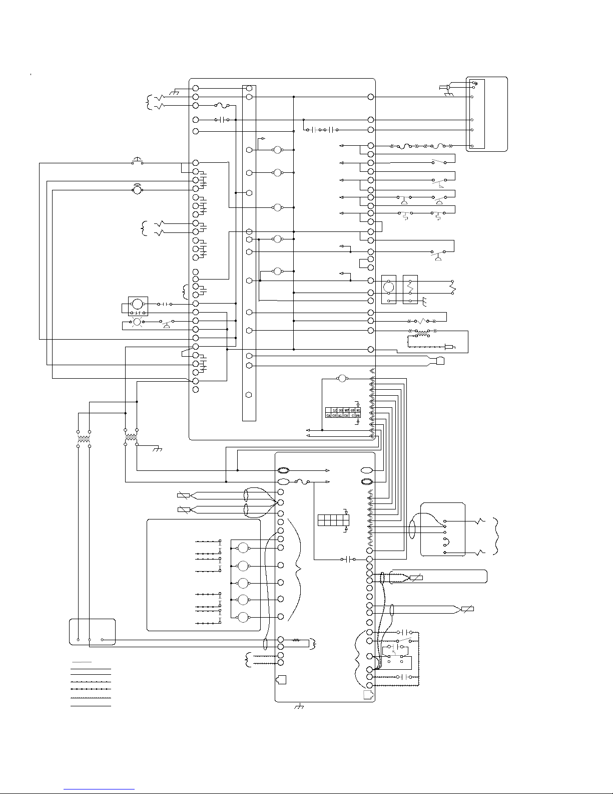
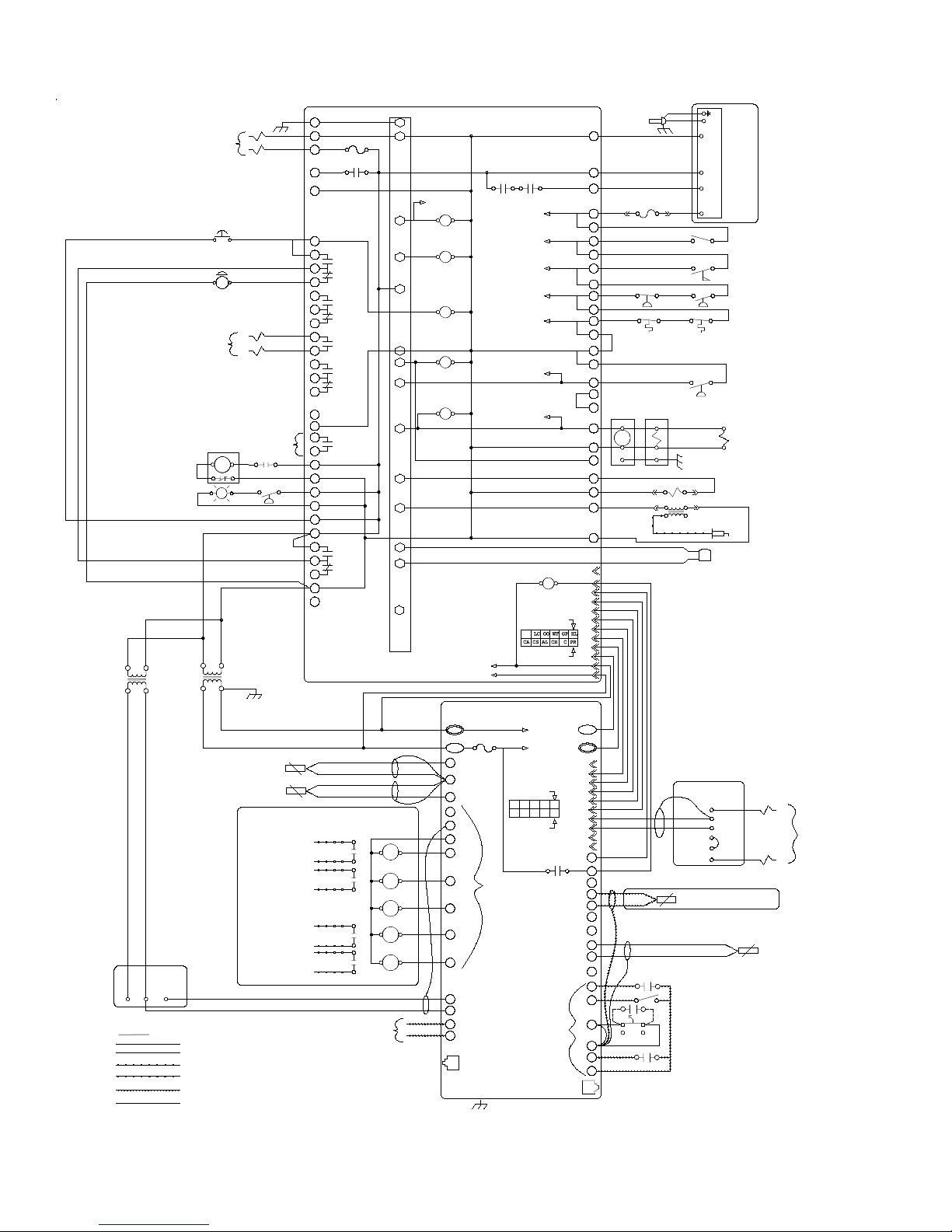
6. e following pages have sample wiring diagrams.
Contact ermal Solutions Representative or visit
website (www.thermalsolutions.com) for current
wiring options.
7. An as-built wiring diagram is included with every
boiler when it ships.
CAUTION
Each boiler must be protected with a dedicated
properly sized fused disconnect.
24
Page 25
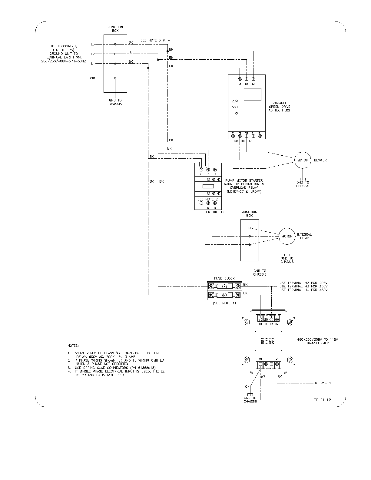
Figure 9a: 208/230/480V - 1PH/3PH - 60HZ Supply Power Wiring Schematic
25
Page 26
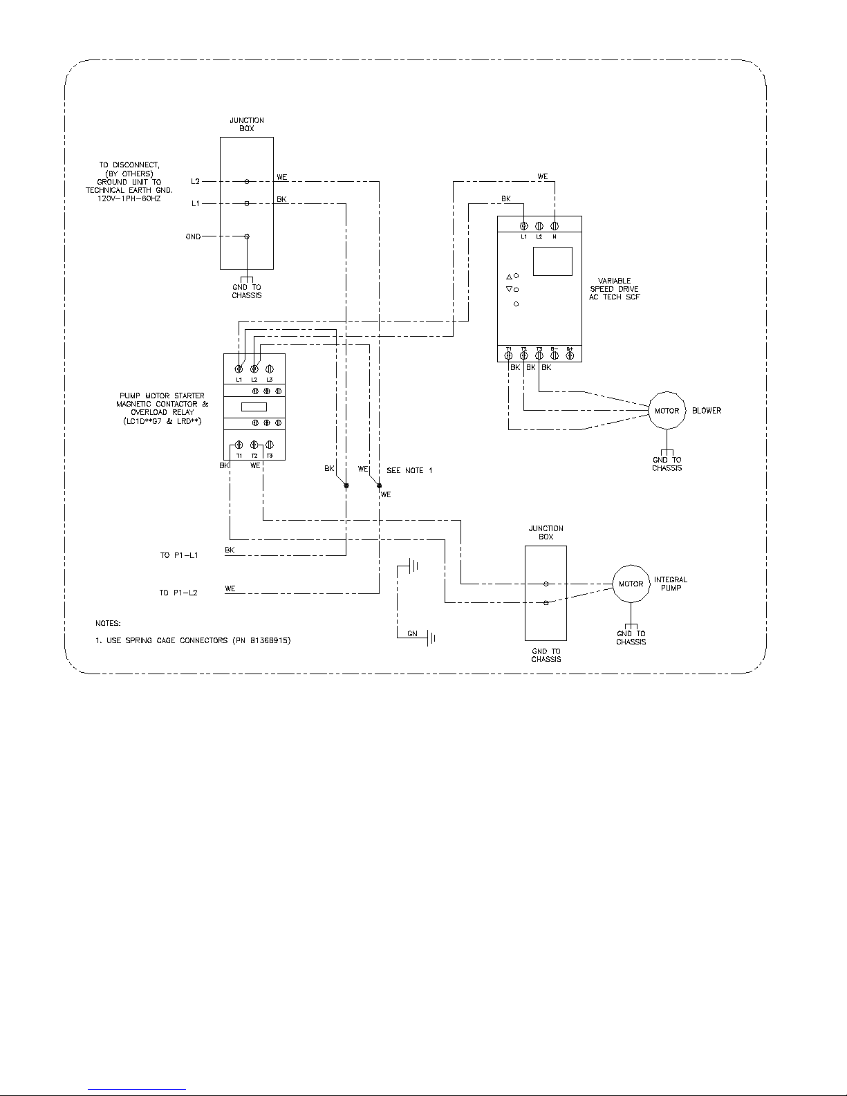
Figure 9b: 120V - 1PH - 60HZ Supply Power Wiring Schematic
26
Page 27
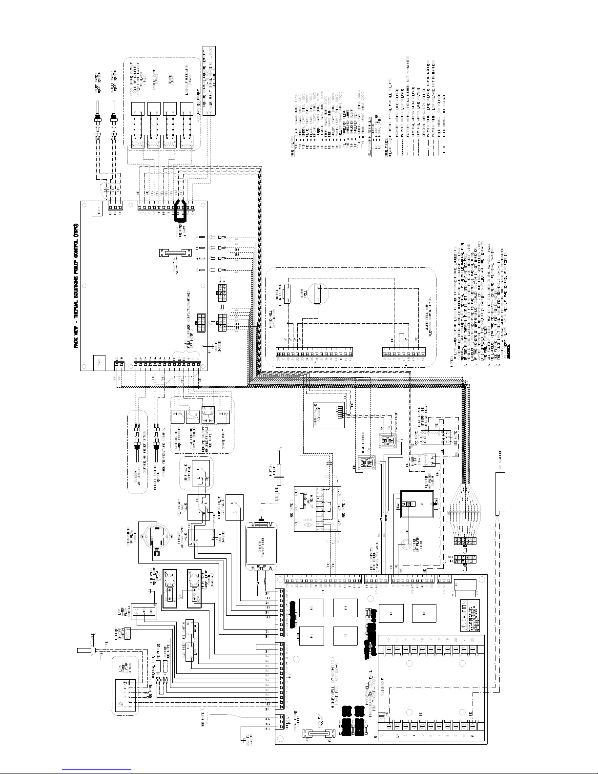
Figure 9c: Control Wiring Schematic (EVCA-750/2000)
27
Page 28
PUMP MOTOR STARTER
AND OVERLOAD RELAY
BLOCKED AIR FILTER
SWITCH AND LIGHT
115V TO 24V
TRANSFORMER
MIXING VALVE
1 2 3
LINE TYPES:
120V-1PH-60HZ
SEE FIGURES 9a&9b FOR
SUPPLY POWER WIRING
ALARM SILENCE
PUSH BUTTON
ALARM BELL
TO VSD
TERMS.
1&2
M
96 95
LT
ACTUATOR
FACTORY WIRING, LINE VOLTAGE
FACTORY WIRING, LOW VOLTAGE (SEE NOTE 2)
FACTORY WIRING, SPECIAL IGNITER
FIELD WIRING, LINE VOLTAGE
FIELD WIRING, LOW VOLTAGE
OPTIONAL WIRING
GND TO
CHASSIS
(2)
(1)
DRY CONTACTS
FOR BOILER
STATUS
INDICATION
A1A2
BOILER PUMP
5 9
CRA3
NO
115V TO 24V
TRANSFORMER
GND TO
CHASSIS
OUTLET
SENSOR
INLET
SENSOR
PROG. SPARE OUTPUT
(COLD AIR DAMPER,
SYSTEM PUMP BACKUP
LOCKOUT INDICATOR
G
L2
L1
29
2
30
31
32
33
34
35
36
37
38
39
40
41
43
44
45
46
3
2
3
C
2
3
3
47
48
49
2
50
OR ALARM)
SYSTEM PUMP
SPARE
CONTROL RELAY OPTIONS
G
2
FUSE
K3
3
K5
K5
K3
K4
K6
K2
REMOTE CONTROL
REMOTE SETPOINT
(VALID INPUT SIGNAL RANGE IS 1-9VDC)
4
5
6
21
9
8
10 28
G
F
0
2
9
13 14
CRA
1
5
9
13 14
CRA
2
5
13 14
CRA
3
9
13 14
CRA
4
5
9
13 14
CRA
5
5
OR
0-10 VDC INPUT
SEE NOTE 6
Q7800H1009 INTERNAL WIRING
4
SENSE
ALARM RELAY K2
K2
LINE VOLTAGE ALARM
K3
BLOWER MOTOR
K5
AUXILIARY RELAY
K4
K6
MAIN FUEL
VALVE(S)
HONEYWELL Q7800H
FLAME SAFEGUARD SUBBASE
AND
PROGRAMMER CONTROL
RM7896D 1027
24VAC -
24VAC +
C
FUSE
PR
BO
BC
BI
C
C
C
SO
SP
BP
VI
LO
1
R
MS
m
h
o
0
0
5
MR
C-
C+
RJ11
GND TO
CHASSIS
K1 K1
SENSE
LOW WATER CUTOFF
SENSE
BURNER ON/OFF
SWITCH
SENSE
WATER FLOW SWITCH
SENSE
GAS PRESS SWITCHES
SENSE
HIGH LIMIT
SENSE
COMBUSTION AIR
FLOW
SENSE
MAIN FUEL VALVE
THERMAL SOLUTIONS
BOILER CONTROL
(TSBC)
CA HL GP WF
OO V- V+ P- P+
12 VDC
0.5A MAX TOTAL
FOR SO, SP, BP,
V1, & LO
4-20 mA DC
CONVERTED TO
2-10 VDC
(FIELD SUPPLIED
CONTACTS/SWITCHES)
CALL FOR
HEAT
24VAC -
24VAC +
Pin 6
Pin 1
K1
11
10
9
8
7
6
5
Pin 7
Pin 1
12 VDC
2
3
10
11
12
13
14
15
16
17
18
19
20
21
22
237
24
25
26
2
42
27
2
2
12
3
11
10
9
8
7
6
5
4
2
1
AL
CS
10
9
8
7
6
5
4
3
2
1
LC
CH
O+
O+
O-
O-
R+
R+
R-
R-
DP
LR
RO
C
SI
C
RJ45
BURNER
THERMAL FUSE
OPTIONAL
SEE NOTE 3
HIGH LOW
HIGH LIMIT OPERATING LIMIT
NC
MANUAL AUTO
PRIMARY SECONDARY
GAS RATIO
GAS
ACTUATOR
VALVE
L
E/H
N
2
1
4
3
REMOTE
LOCAL
P
2
1
BURNER ON/OFF SWITCH
WATER FLOW SWITCH
HIGH AND LOW GAS
PRESSURE SWITCHES
HIGH LIMIT AND OPERATING
TEMPERATURE SWITCHES
UNUSED OPERATING LIMIT
COMBUSTION AIR FLOW
SWITCH
VENT VALVE
(OPTIONAL)
INTERRUPTED
IGNITION PILOT
GAS VALVE
UV SCANNER
2
5
OUTSIDE AIR
RESET OPTION
3
5
IGNITION XFMR
IGNITION PILOT
COMBUSTION BLOWER
SPEED CONTROL
CIRCUIT
REMOTE SYSTEM
SENSOR
VESTIBULE
THERMAL FUSE
CNO
CNC
L
N
CNO
NC
CC
CNO
GND TO
CHASSIS
VARIABLE
SPEED DRIVE
AC Tech SCF
1
12
2
2
OUTSIDE AIR
SENSOR
DOMESTIC HOT WATER PRIORITY
DOMESTIC HOT WATER PRIORITY
LOCAL/REMOTE(REMOTE CONTROL OR REMOTE SETPOINT)
LOCAL/REMOTE(REMOTE CONTROL OR REMOTE SETPOINT)
REMOTE ON/OFF(ENABLE/DISABLE)
SEE NOTE 5
SPARE INPUT
SPARE INPUT
MM 750-
MT-120
LOW WATER
CUTOFF
OPTION
(SEE NOTE 1)
(38)
(37)
TO K3
RELAY ON
FLAMESAFEGUARD
SUBBASE
TERM. 37 & 38
Figure 9d: Ladder Wiring Diagram (EVCA-750/2000)
28
Page 29
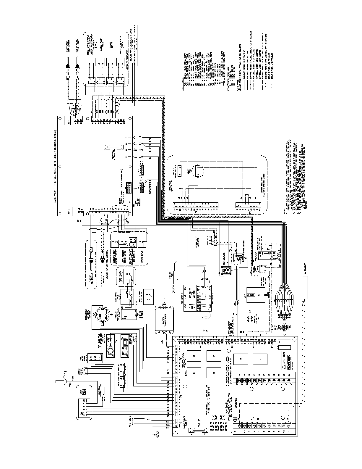
Figure 9e: Control Wiring Schematic (EVCA-3000)
29
Page 30
120V-1PH-60HZ
SEE FIGURES 9a&9b FOR
SUPPLY POWER WIRING
PUMP MOTOR STARTER
AND OVERLOAD RELAY
BLOCKED AIR FILTER
SWITCH AND LIGHT
115V TO 24V
TRANSFORMER
ALARM SILENCE
PUSH BUTTON
ALARM BELL
TO VSD
TERMS.
1&2
A1A2
M
96 95
LT
TRANSFORMER
(2)
(1)
BOILER PUMP
115V TO 24V
GND TO
CHASSIS
DRY CONTACTS
FOR BOILER
STATUS
INDICATION
5 9
CRA3
NO C
G
L2
FUSE
L1
K3
29
2
30
31
K5
32
33
34
35
K5
36
37
K3
38
39
K4
40
41
43
44
45
K6
46
3
2
3
2
3
3
47
K2
48
49
2
50
Q7800H1009 INTERNAL WIRING
G
2
AND
24VAC -
24VAC +
K1 K1
SENSE
LOW WATER CUTOFF
SENSE
BURNER ON/OFF
SWITCH
SENSE
WATER FLOW SWITCH
SENSE
GAS PRESS SWITCHES
SENSE
HIGH LIMIT
SENSE
COMBUSTION AIR
FLOW
SENSE
MAIN FUEL VALVE
K1
CALL FOR
HEAT
11
10
9
8
7
6
5
12
11
10
Pin 7
Pin 1
4
SENSE
ALARM RELAY K2
K2
3
LINE VOLTAGE ALARM
K3
4
BLOWER MOTOR
5
K5
AUXILIARY RELAY
6
21
K4
K6
9
MAIN FUEL
VALVE(S)
8
10 28
G
F
HONEYWELL Q7800H
FLAME SAFEGUARD SUBBASE
0
2
PROGRAMMER CONTROL
RM7896D 1027
2
3
10
11
12
13
14
15
16
17
18
19
20
21
22
237
24
25
26
2
42
27
2
2
3
9
8
7
6
5
4
2
1
VESTIBULE
THERMAL FUSE
HIGH LOW
CNC
HIGH LIMIT OPERATING LIMIT
NC
MANUAL
PRIMARY SECONDARY
GAS RATIO
GAS
ACTUATOR
VALVE
L
E/H
N
N
L
NC
AUTO
GND TO
CHASSIS
P
2
1
MM 750MT-120
3
LOW WATER
CUTOFF
5
BURNER ON/OFF SWITCH
WATER FLOW SWITCH
CNO
HIGH AND LOW GAS
PRESSURE SWITCHES
CNO
HIGH LIMIT AND OPERATING
TEMPERATURE SWITCHES
CC
UNUSED OPERATING LIMIT
COMBUSTION AIR FLOW
SWITCH
CNO
VENT VALVE
(OPTIONAL)
INTERRUPTED
IGNITION PILOT
GAS VALVE
UV SCANNER
IGNITION XFMR
IGNITION PILOT
G G0 Y
LINE TYPES:
MIXING VALVE
ACTUATOR
FACTORY WIRING, LINE VOLTAGE
FACTORY WIRING, LOW VOLTAGE (SEE NOTE 2)
FACTORY WIRING, SPECIAL IGNITER
FIELD WIRING, LINE VOLTAGE
FIELD WIRING, LOW VOLTAGE
OPTIONAL WIRING
GND TO
CHASSIS
OUTLET
SENSOR
INLET
SENSOR
PROG. SPARE OUTPUT
COLD AIR DAMPER,
SYSTEM PUMP BACKUP
OR ALARM
SYSTEM PUMP
SPARE
LOCKOUT INDICATOR
CONTROL RELAY OPTIONS
9
13 14
CRA
1
5
9
13 14
CRA
2
5
13 14
CRA
3
9
13 14
CRA
4
5
9
13 14
CRA
5
5
REMOTE CONTROL
OR
REMOTE SETPOINT
0-10 VDC INPUT
(VALID INPUT SIGNAL RANGE IS 1-9VDC)
SEE NOTE 2
THERMAL SOLUTIONS
BOILER CONTROL
(TSBC)
C
FUSE
PR
BO
BC
BI
C
C
C
SO
SP
12 VDC
0.5A MAX TOTAL
FOR SO, SP, BP,
V1, & LO
BP
VI
LO
MS
MR
C-
C+
RJ11
GND TO
CHASSIS
24VAC -
24VAC +
Pin 6
CA HL GP WF
OO V- V+ P- P+
Pin 1
(FIELD SUPPLIED
CONTACTS/SWITCHES)
12 VDC
AL
CS
10
9
8
7
6
5
4
3
2
1
LC
CH
O+
O+
O-
O-
R+
R+
R-
R-
DP
LR
RO
C
SI
C
RJ45
LOCAL
2
1
4
3
REMOTE
VARIABLE
SPEED DRIVE
AC Tech SCF
1
12
2
2
OUTSIDE AIR
SENSOR
DOMESTIC HOT WATER PRIORITY
DOMESTIC HOT WATER PRIORITY
LOCAL/REMOTE(REMOTE CONTROL OR REMOTE SETPOINT)
LOCAL/REMOTE(REMOTE CONTROL OR REMOTE SETPOINT)
REMOTE ON/OFF(ENABLE/DISABLE)
REMOTE ON/OFF(ENABLE/DISABLE)
SEE NOTE 3
SPARE INPUT
SPARE INPUT
2
5
COMBUSTION BLOWER
SPEED CONTROL
CIRCUIT
OUTSIDE AIR
RESET OPTION
(38)
(37)
REMOTE SYSTEM
SENSOR
TO K3
RELAY ON
FLAMESAFEGUARD
SUBBASE
TERM. 37 & 38
Figure 9f: Ladder Wiring Diagram (EVCA-3000)
30
Page 31

G. MODULAR SYSTEMS
1. General Guidelines
a. Read and follow all venting, combustion
air, water piping, gas piping and electrical
instructions contained in this manual unless
otherwise instructed in this section.
b. Modular systems are complex. Design and
installation of modular systems should only
be undertaken by skilled and knowledgeable
engineers and contractors.
c. Consult Local Building Codes, National Fuel Gas
Code, or NFPA 54/ANSI Z223.1 for restrictions
and instructions for modular boilers.
d. Refer to the Pre-Installation section for further
warnings, cautions, notices and instructions.
2. Module Sizing
Consult factory for recommended number and
size of boilers for a given input.
3. Venting
a. Refer to Venting Section for sidewall and vertical
venting guidelines.
b. Each boiler requires an individual vent pipe.
c. e minimum horizontal distance between
vent terminations is one (1) foot. Additional
horizontal distance is desirable to avoid frost
damage to the building. Vent terminations must
be at least twelve (12) inches above the ground
plus the expected snow accumulation.
d. IMPORTANT: Refer to the Venting section
for further warnings, cautions, notices and
instructions.
4. Air Intake Piping
a. Consult intake pipe manufacturer for common
air intake pipe sizing.
b. Refer to Figures 10 and 11 for common air intake
guidelines for modular boilers.
c. Individual air intake pipes may be used in lieu of
common air intake piping.
d. Common air intake straight lengths and ttings
should be assumed to have the equivalent length
the same as an individual air intake pipe, used for
a given boiler intake pipe diameter.
e. Position horizontal air intake termination center
line below horizontal vent termination's center
line.
f. Vertical air intake pipe must terminate at least
two (2) feet above the closest portion of the roof.
g. IMPORTANT: Refer to the Combustion Air
section for further warnings, cautions, notices
and instructions.
5. Water Piping
a. Refer to Figure 12 for the recommended piping
arrangement on modular boiler systems. Refer
to Figures 13, 14, 15, 16 or 17 for alternate piping
arrangements on modular boiler systems.
b. Installing a low water cut-o in the system piping
is highly recommended and may be required by
Code, if not factory-mounted on boiler.
c. Refer to Table 1b for pressure drop for each
boiler.
d. Consult I=B=R Installation and Piping Guide.
e. Maintain ½" minimum distance between water
piping and combustible material.
f. Refer to Water Piping and Trim Section
for further warnings, cautions, notices and
instructions.
NOTICE
The pressure drop given in Table 1B is for the
boiler only. The pressure drop of each system
tting and component must be added to the
boiler pressure drop to determine the system
pressure head requirement. See Table 5 for
tting and component equivalent lengths.
CAUTION
Proper water treatment is required. The water
shall have a maximum water hardness of 8.5
grains or 150 ppm. The recommended pH range
is 8.8 to 9.2.
6. Gas Piping
a. Refer to National Fuel Gas Code, Local Codes
and Tables 2 through 6 for gas pipe sizing.
b. Refer to Gas Piping Section for further warnings,
cautions, notices and instructions.
31
Page 32
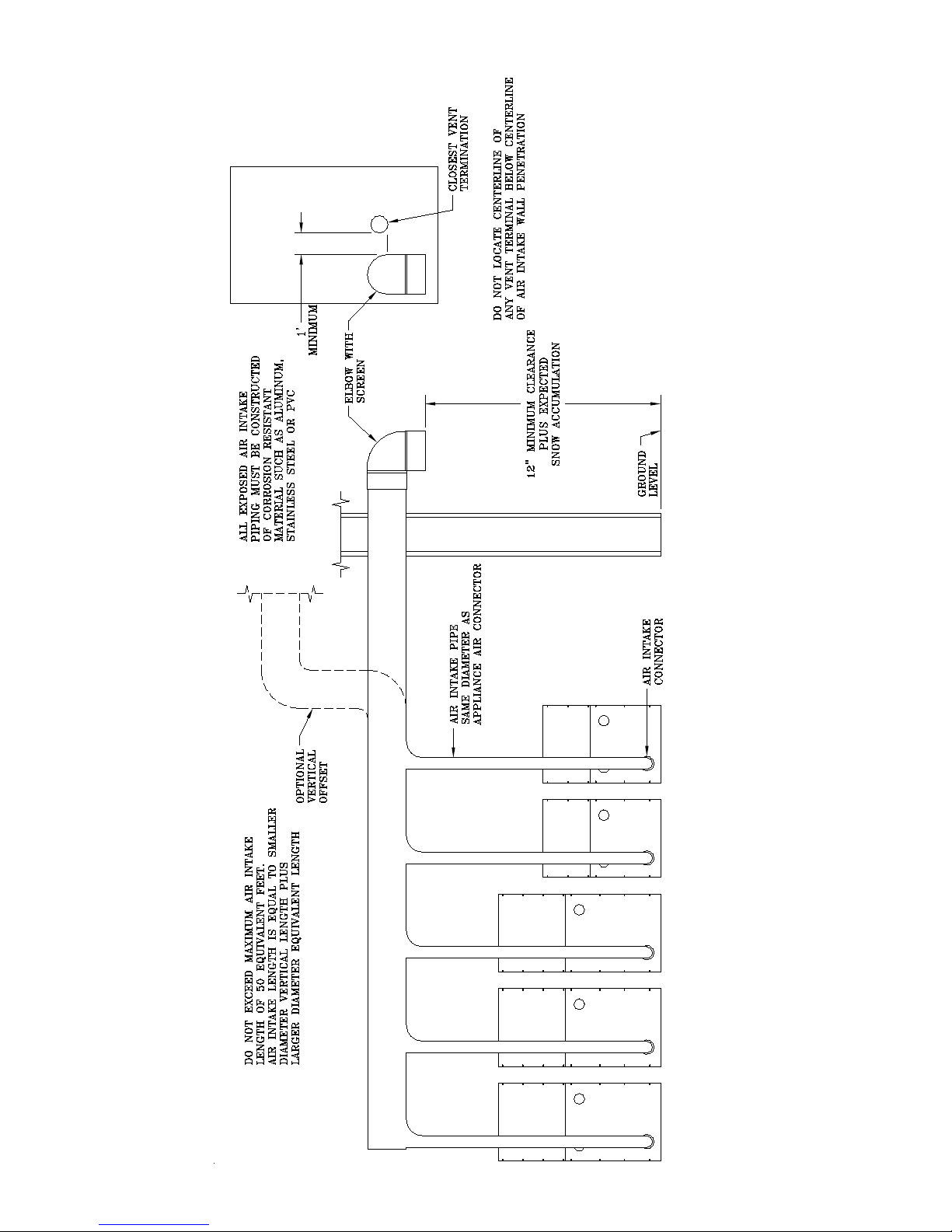
Figure 10: Modular System Horizontal Air Intake Piping
32
Page 33
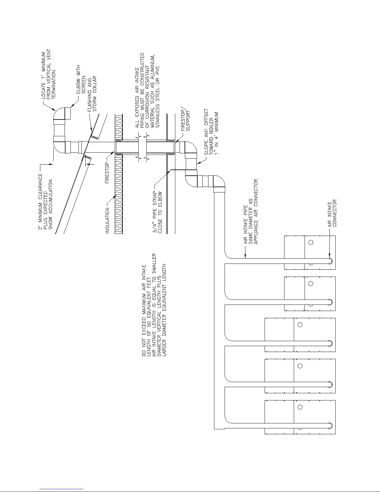
Figure 11: Modular System Vertical Air Intake Piping
33
Page 34
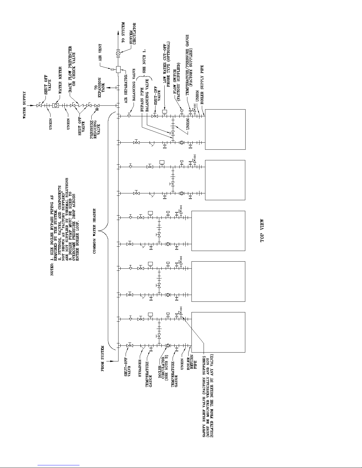
Figure 12: Modular System: Typical One Pipe Water Piping
34
Page 35
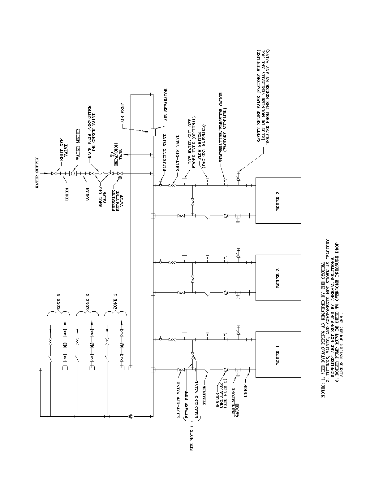
Figure 13: Modular System: Typical Primary/Secondary Water Piping
35
Page 36
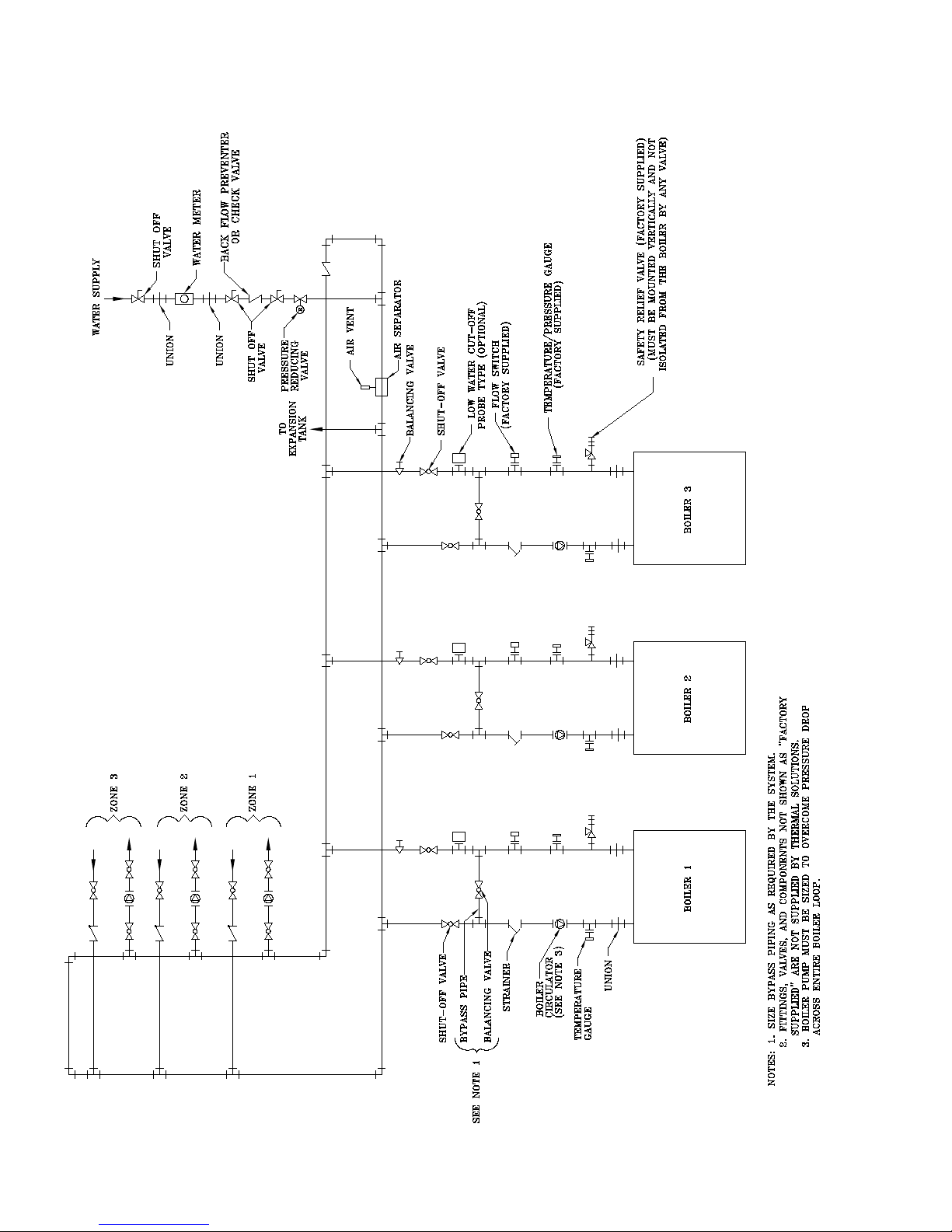
Figure 14: Modular System: Typical Primary/Secondary without System Pump
36
Page 37
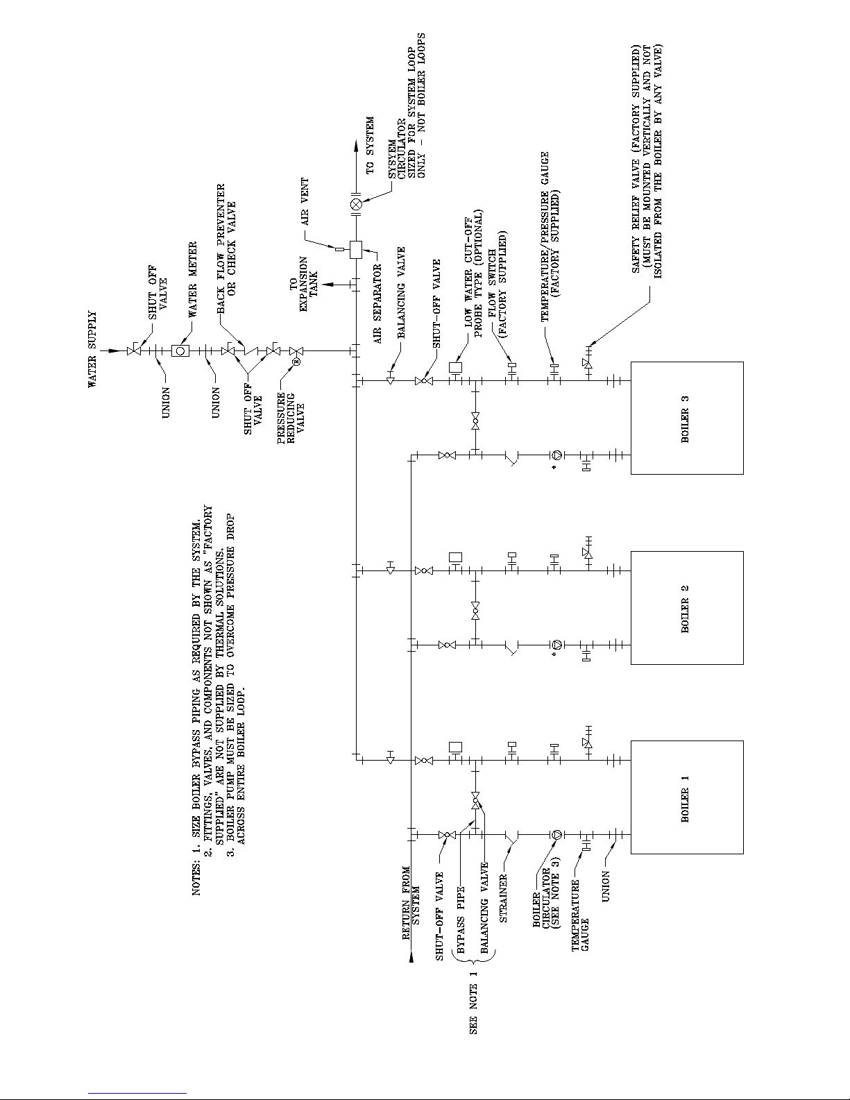
Figure 15: Modular System: Typical Reverse - Return Water Piping
37
Page 38
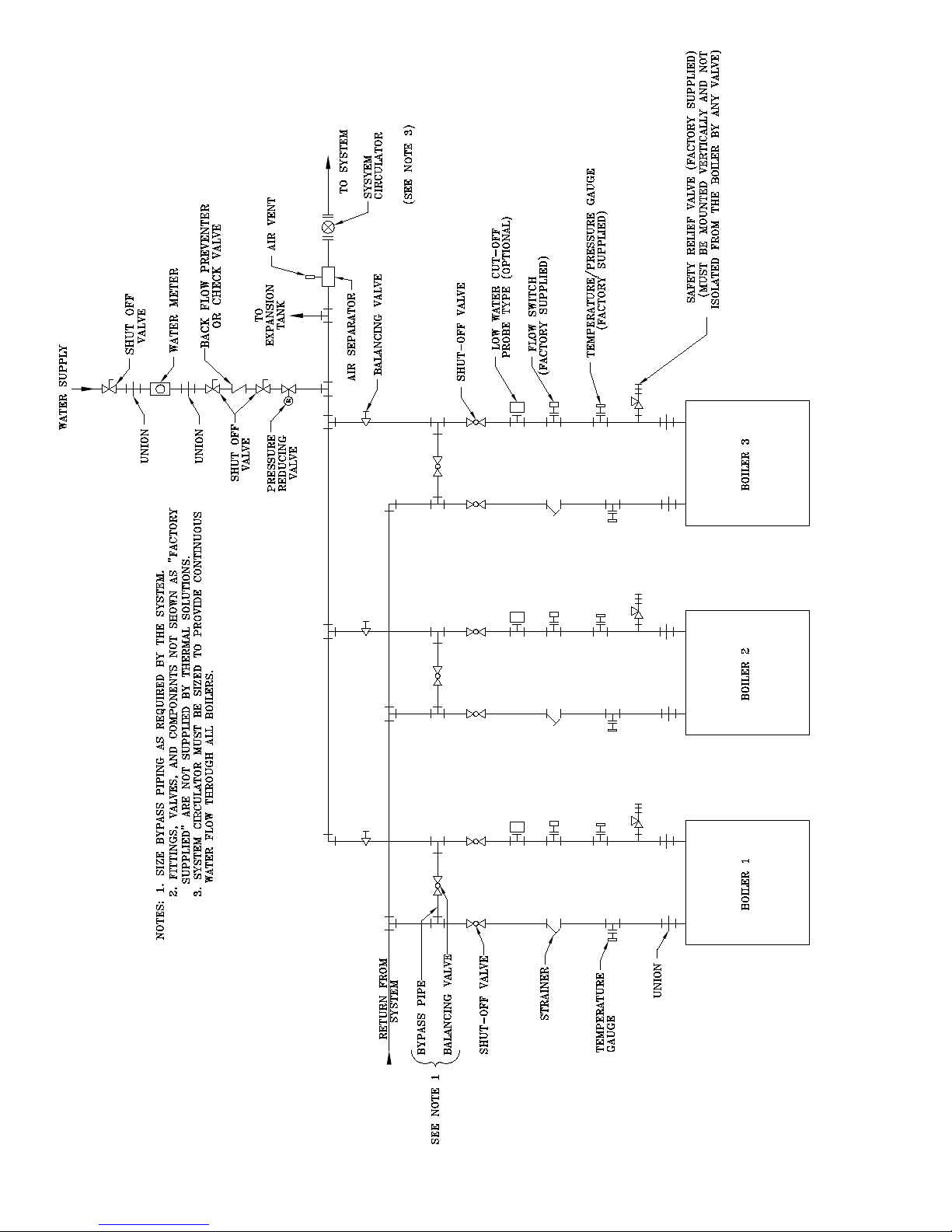
Figure 16: Modular System Reverse - Return with System Pump Only
38
Page 39
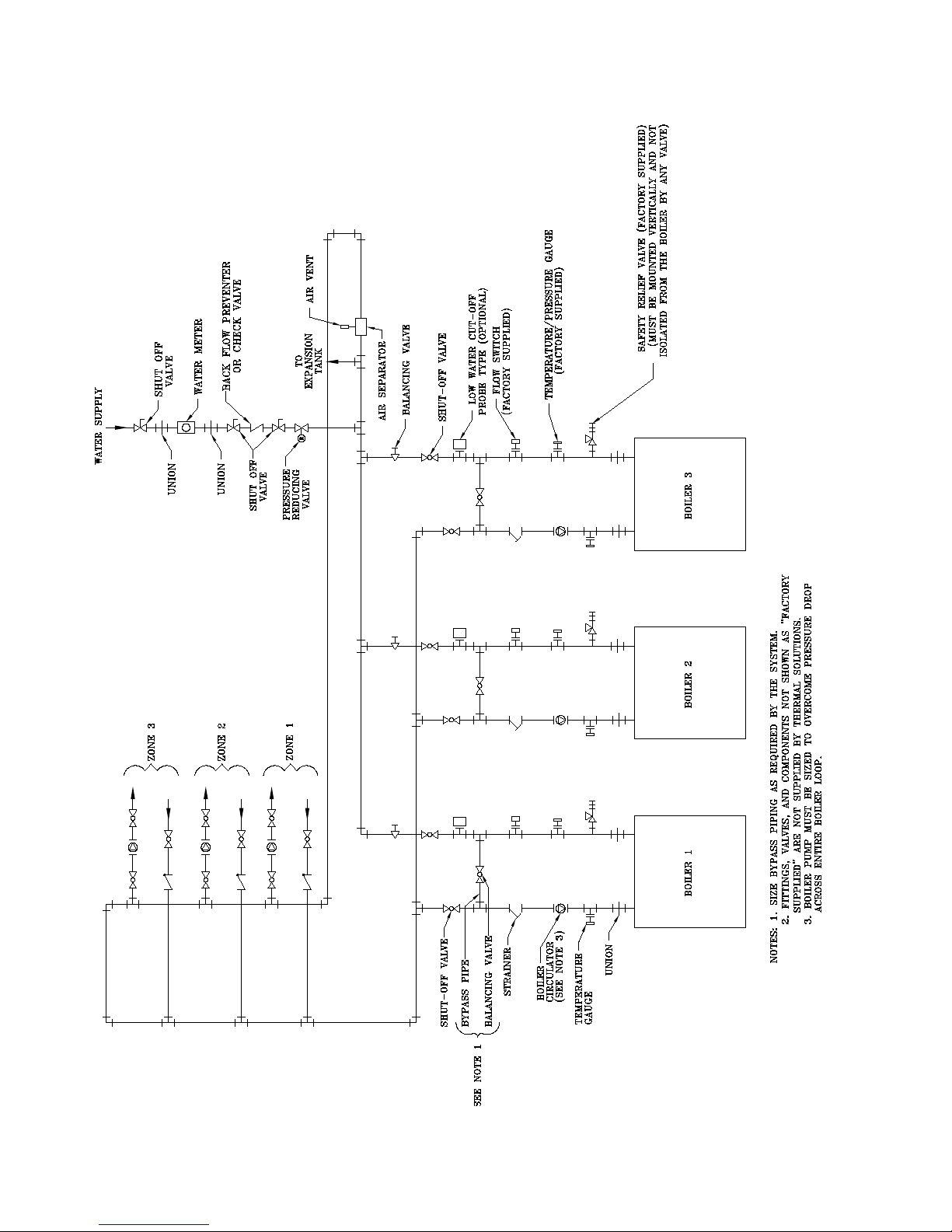
Figure 17: Modular System: Typical Primary/Secondary with Reverse-Return
39
Page 40

7. Electrical
a. Each boiler must be provided with a dedicated
fused disconnect.
b. Install wiring and ground boiler in accordance
with requirements of authority having
jurisdiction. In absence of such requirements,
reference the National Electrical Code, ANSI/
NFPA 70 and/or CSA C22.1 Electrical Code.
c. Refer to Figure 1 for electrical data for each size
boiler.
d. Refer to the Electrical Section for further
warnings, cautions, notices and instructions.
NOTICE
Do not install boiler and circulator pump on the
same fused disconnect.
8. Condensate Piping
a. Each boiler requires separate condensate drains.
In addition, most venting congurations require
separate condensate drains in the vent system.
H. CONDENSATE DRAINS
1. Each boiler has two condensate drains - one from
the primary heat exchanger, and one from the
secondary heat exchanger. In addition, most vent
congurations require a drain tee located in the vent
piping. Pipe each condensate drain separately to a
oor drain or condensate pump/sump. See Table 7
for maximum condensate ow rates.
2. Use continuous Teon, high temperature resistant
silicone tubing, or other tubing material compatible
with ue gas condensate for condensate piping.
CAUTION
Failure to properly pipe condensate system will
greatly reduce boiler life. Do not install plugs,
caps or valves on condensate piping.
Do not manifold boiler condensate drains or vent
drains together.
Do not crimp condensate lines or reduce drain
line inner diameter size.
Each condensate drain must contain a siphon/
pigtail or trap to prevent ue gas ow through
the condensate piping. The height of the top of
the siphon/pigtail loop or trap shall not exceed
the height of the condensate drain outlet.
3. A common condensate pump/sump may be used.
Run separate piping from each condensate drain
to the sump. A common drain may be used to
discharge condensate from the sump. Consult
pump/sump manufacturer for compatibility of
pump/sump materials of construction. If a common
sump is used, individual drain lines should be
connected such that one drain cannot back feed into
another drain.
4. Consult local authorities regarding disposal of ue
gas condensate into public waste water system.
Some jurisdictions require that the condensate
be buered before discharge. is buering is
commonly achieved by draining the condensate
through a limestone bed. e condensate will be
slightly acidic and range between 3 - 5 on the pH
scale. Consult ermal Solutions or a chemical
treatment company for buering systems.
TABLE 7: MAXIMUM CONDENSATE
FLOW
Boiler
Model
Condensate Flow (gal/hr)
EVCA-750 3.4
EVCA-1000 4.5
EVCA-1500 6.8
EVCA-2000 9.1
EVCA-3000 18.6
Maximum
CAUTION
Do not use material that is not approved for use
with ue gas condensate for condensate piping.
40
Page 41
IV. System Start-up
CAUTION
Failure to properly pipe boiler may result in
improper operation and damage to boiler or
structure.
Oxygen contamination of boiler water will cause
corrosion of iron and steel boiler components,
and can lead to boiler failure. Thermal Solutions
Standard Warranty does not cover problems
caused by oxygen contamination of boiler water.
Proper water treatment is required to avoid scale
build-up on the inside of the boiler. Thermal
Solutions standard warranty does not cover
problems caused by scale build-up.
All piping either new or existing must be cleaned
with a tri sodium phosphate (TSP) solution to
remove mill scale and oils from the system.
Failure to do so could result in premature failure
of the heat exchanger (not covered by Thermal
Solutions warranty).
On an existing or retrot system, a lter or
strainer must be installed on the system return
prior to the boilers.
When using Glycol products, all Glycol manu-
factures' requirements, including rust inhibitors,
must be adhered. Max 50% Glycol.
A. System Check
1. Verify that the venting, water piping, gas piping and
electrical system are installed properly. Refer to
installation instructions contained in this manual.
WARNING
Completely read, understand and follow all
instructions in this manual, Honeywell ame
safeguard, and all other component manuals
supplied with this boiler before attempting start
up.
2. Conrm all electrical, water and gas supplies are
turned o at the source and that chimney/vent
is clear of obstructions. If boiler is controlled by
an external control system, this system must be
temporarily disconnected. e local boiler controls
should be allowed to operate the boiler.
3. Remove the upper front jacket panel.
WARNING
Prior to pressurizing the boiler water supply
system, be sure the boiler piping air vent is
properly installed. Refer to water piping section
of this manual.
CAUTION
This boiler contains a manual gas shut-off valve
inside of the upper front jacket panel
B. Pressurize the Hydronic System - ll entire heating
system with water and vent air from system. Use the
following procedure on a Series Loop or multi-zoned
system installed to remove air from the system while
lling.
1. Close full port ball valve in boiler supply piping.
2. Isolate all zones by closing zone valves or shut-o
valves in supply and return of each zone(s).
3. Attach a hose to the hose bib in system piping and
terminate hose in a ve gallon bucket at a suitable
oor drain or outside area.
4. Starting with one circuit at a time, open zone valve
or shut-o valve in system supply and return piping.
a. Open hose bib.
b. Open ll valve (Make-up water line should be
located directly aer full port ball valve in system
supply piping between air scoop and expansion
tank).
c. Allow water to overow from bucket until
discharge from hose is bubble free for 30 seconds.
d. Close the opened zone valve or shut-o valve for
the zone being purged of air, then open the zone
valve or shut-o valve for the next zone to be
purged. Repeat this step until all zones have been
purged. At completion, open all zone valves or
shut-o valves.
5. Close hose bib, continue lling the system until the
pressure gauge indicates required system operating
pressure. Close ll valve.
(Note - if make-up water line is equipped with
pressure reducing valve, system will automatically
ll to set pressure. Follow ll valve manufacturer's
instructions).
6. Open isolation valve in boiler supply piping.
7. Remove hose from hose bib.
8.
Conrm that the boiler and system have no water leaks.
4. Conrm that all manual shut-o gas valves between
the boiler and gas supply are closed.
CAUTION
For the EVCA-3000, do not open or adjust mixing
valve actuator rotating knob at the top of the
actuator. This will affect proper boiler operation.
41
Page 42

WARNING
The maximum operating pressure of this boiler
is 160 psig. Never exceed this pressure. This
boiler was supplied with a safety relief valve with
a pressure relief setting specied at the time of
purchase. The relief valve setting must be above
the maximum operating pressure of the system.
Consult Thermal Solutions if the desired system
operating pressure is above the safety relief
valve pressure setting. Do not plug or change
safety relief valve.
C. Power the boiler - Turn on electrical supply to the
boiler and circulation system at fused disconnect
switches. Note that there is electrical power at certain
components even with the power switch o. See wiring
diagrams in Figures 9a-9f.
D. Power the Circulators - Turn system circulators on
and purge air from the boiler and system piping.
1. Conrm motor rotation on boiler and system
circulators.
2. Conrm that water ow switch is operating properly.
E. Pressurize the Fuel System - Turn on gas supply to the
boiler gas piping.
1. Conrm that the supply pressure to the gas regulator
supplied with the boiler conforms to Table 2 for
maximum and minimum supply pressures.
2. Open the manual gas shut-o valves located
upstream of the gas regulator supplied with the
boiler. Do not open manual gas valve inside of boiler
jacket.
DANGER
Do not use matches, candles, open ames or
other ignition source to check for leaks.
3. Using soap solution, or similar non-combustible
solution, electronic leak detector or other approved
method, check that boiler gas piping valves,
regulators and all other components are leak free.
Eliminate any leaks.
4. Purge gas line of air.
5. Reset low gas pressure safety switch.
F. Select Operational Mode - Refer to the ermal
Solutions Boiler ControlTM (TSBCTM) Instruction
Manual to select the desired control features.
G. Check Blower Rotation - Remove air lter to expose
the fan blades.
1. Allow boiler to enter the sequence of operation.
2. While in Pre-Purge, position the ame control to the
test position.
3. Conrm proper blower motor rotation.
4. Shut boiler o and position the ame control back to
run. Reinstall air lter.
H. Flame Safeguard Operation Check - Turn boiler
operating switch to the ON position.
1. Allow boiler to complete prepurge and trial for
ignition period. Once pilot ame is recognized by
controller, position ame control switch to TEST
position.
2. Look through the boiler sight glass and conrm
that pilot ame is blue and steady and that the ame
signal is steady and between 1.5 and 5.0 volts DC.
On some boiler sizes, the pilot ame may not be
visible. In these cases, conrm proper ame signal
(as indicated above.)
3. Adjust pilot gas regulator until proper pilot manifold
gas pressure is achieved per retest report label.
Pilot ame should be blue with very little yellow.
4. Turn the boiler o, place ame control switch in
"run" position, and repeat Steps H.1 and H.2 at least
ve times until reliable pilot ignition and signal is
achieved and conrmed.
5. With the pilot operating properly, allow boiler to
continue to trial for main ame. Conrm that the
ame control locks out on main ame failure.
6. Open the manual main gas shut-o valve located
inside the boiler jacket. Using the procedure detailed
in Step E.3, leak test gas piping and valves inside of
jacket. Eliminate any leaks.
7. Reset ame safeguard and allow boiler to run
through prepurge, trial for pilot and trial for main
ame.
8. Conrm that main ame ignites smoothly.
9. Observe main ame and conrm that burner
element is evenly orange without ickering.
10. Observe ame signal and conrm signal is steady
and between 1.5 and 5.0 volts DC.
11. Using the procedure detailed in step E.3, leak test
gas piping and valves inside of jacket. Eliminate any
leaks.
12. Turn boiler o and repeat Steps H.7-H.10 at least
ve times to conrm proper main burner operation.
I. Begin Commissioning the boiler - With main ame
on, at high re, measure gas pressure upstream and
downstream of the main gas valves
1. Adjust the manifold pressure to match the pressure
indicated on the factory retest label.
2. Reassure that the inlet gas pressure is within the
acceptable range found in Table 2. Adjust if
necessary.
42
Page 43

WARNING
Failure to properly adjust gas input rate will
result in over ring or under ring of the
appliance. Improper and unsafe boiler operation
may result.
temperature operating control, manual reset water
temperature safety limit, vestibule fuseable link,
mixer fuseable link, high and low gas pressure
switches. Refer to manuals for these components for
proper start-up and operating instructions. Follow
all instructions contained in these manuals. is
manual was provided with the boiler.
3. Conrm that high and low gas pressure switches are
functioning and are adjusted to prevent over ring
or under ring of the boiler.
4. Adjust setting of air lter ow switch by rotating
knob on switch counter clockwise until change
lter light switch is illuminated. Turn switch knob
clockwise ¼ turn past the point where the change
lter light goes out. Replace upper front jacket
panel.
5. With boiler running and all panels attached,
measure oxygen (O2) and carbon monoxide
(CO) concentrations in the ue gas and ue gas
temperature. Compare results with values given on
factory retest report supplied with the boiler.
DANGER
Failure to properly adjust excess air will result
in unsafe levels of carbon monoxide. Variations
in venting or combustion air pressure and
temperature will change excess air. Adjust
excess air levels so that variation in venting
or combustion air pressures and temperatures
caused by change of seasons, wind conditions,
opening or closing of boiler room doors or
windows do not cause the boiler to operate with
carbon monoxide concentrations above 400
parts per million.
J. Finish Commissioning at the Boiler - Reconnect any
wires from the external control system, if applicable.
1. Test function of external control system.
2. Place system control back in normal operation, if
necessary.
K. Water Treatment - Contact reputable chemical
treatment company for recommendations on proper
water treatment for the installation. Each installation
is dierent and must be analyzed based on local water
conditions and boiler operating schedule.
e treatment chemicals must be compatible with
copper, bronze, steel and cast iron materials of
construction.
6. Verify that all safety and operating limits and ame
controls are operating properly. ese controls
and limits include combustion air switch, water
CAUTION
A proper water treatment and monitoring program will extend the life of the boiler. The water shall have
a maximum water hardness of 8.5 grains or 150 ppm. The recommended pH range is 8.8 to 9.2. However,
other aspects of water quality can affect boiler operation and longevity. A qualied water treatment expert
should be consulted to develop a complete water treatment plan.
WARNING
Chemicals used in treating boiler water are toxic and/or harmful. Always use protective clothing and
equipment when working with/near chemicals. Contact local authorities to determine if treated boiler water
can be discharged into local waste water system.
43
Page 44
V. Lighting Instructions
FOR YOUR SAFETY, READ BEFORE OPERATING
WARNING: If you do not follow these instructions exactly, a re or explosion may result
causing property damage, personal injury, or loss of life.
A. is appliance is equipped with an ignition device
which automatically lights the pilot. Do NOT try to
light the pilot by hand.
B. BEFORE OPERATING smell all around the appliance
area for gas. Be sure to smell next to the oor because
some gas is heavier than air and will settle on the oor.
WHAT TO DO IF YOU SMELL GAS
• Do not try to light any appliance.
• Do not touch any electric switch; do not use any
phone in your building.
• Immediately call your gas supplier from a neighbor's
phone. Follow the gas supplier’s instructions.
OPERATING INSTRUCTIONS
1. STOP! Read all the safety information (warnings,
cautions etc.) in this manual.
2. Turn o all electric power to the appliance.
3. Set the system control so that there is no call for heat
to the appliance.
4. is appliance is equipped with an ignition device
which automatically lights the pilot and main
burner. Do not try to light the pilot or main ame
by hand.
5. Remove front door panel.
6. Locate the gas pilot valve at the rear of the appliance.
7. Locate the gas main valves at the rear of the
appliance and at the end of the gas supply pipe inside
the appliance.
• If you cannot reach your gas supplier, call the re
department.
C. Do not use this appliance if any part has been under
water. Immediately call a qualied service technician
to inspect the appliance and to replace any part of the
control system and any gas control which has been
under water.
10. Rotate gas shuto valves counterclockwise
from "OFF" to "ON". Make sure handle rests against
stop. Do not force.
12. Turn on all electric power to the appliance.
13. Set thermostat to desired setting.
14. If the appliance will not operate, follow
the instructions " TO TURN OFF GAS TO
APPLIANCE" and call your service technician or
gas supplier.
15. Move the switch to the "ON" position.
8. Rotate gas shuto valves clockwise from
"ON" position to "OFF". Make sure handle rests
against stop.
9. Wait ve (5) minutes to clear out any gas. en smell
for gas, including near the oor. If you smell gas,
STOP! Follow "B" in the safety information above on
this label. If you do not smell gas, go to the next step.
16. Set system control so that there is a call for heat
from the system.
17. Observe prepurge, pilot ignition and main ame
ignition.
18. If pilot or main ame ignition does not occur
during initial attempt, remove the upper front jacket
panel of the appliance. If the appliance pilot and
main ame light, go to step 20.
44
Page 45
OPERATING INSTRUCTIONS CONTINUED
19. Reset the burner control by pressing the reset button
located on the burner control. If you do not know
where the control reset button is, do not touch any
part of the control system or wiring. Turn all gas
and electrical power o to the appliance and call a
qualied service technician.
20. Replace the upper front jacket panel.
To Turn Off Gas To Boiler
21. Observe several on and o cycles of the water heater.
If any light os are excessively noisy or rough, or any
questionable boiler operation is noticed, immediately
turn o all gas and electrical power and call qualied
service technician.
22. Should overheating occur or the gas supply fail
to shut o, turn o the manual gas control to the
appliance.
1. Set the thermostat to lowest setting.
2. Turn o electric power to the appliance if service is to
be performed.
3. Remove front door.
4. Rotate gas main shuto valves, located inside the
appliance, clockwise from "ON" position to
"OFF". Make sure handle rests against stop.
5. Replace front door.
6. At the rear of the unit, rotate the pilot and main gas
valves clockwise from "ON" position to
"OFF". Make sure handle rests against stop.
45
Page 46
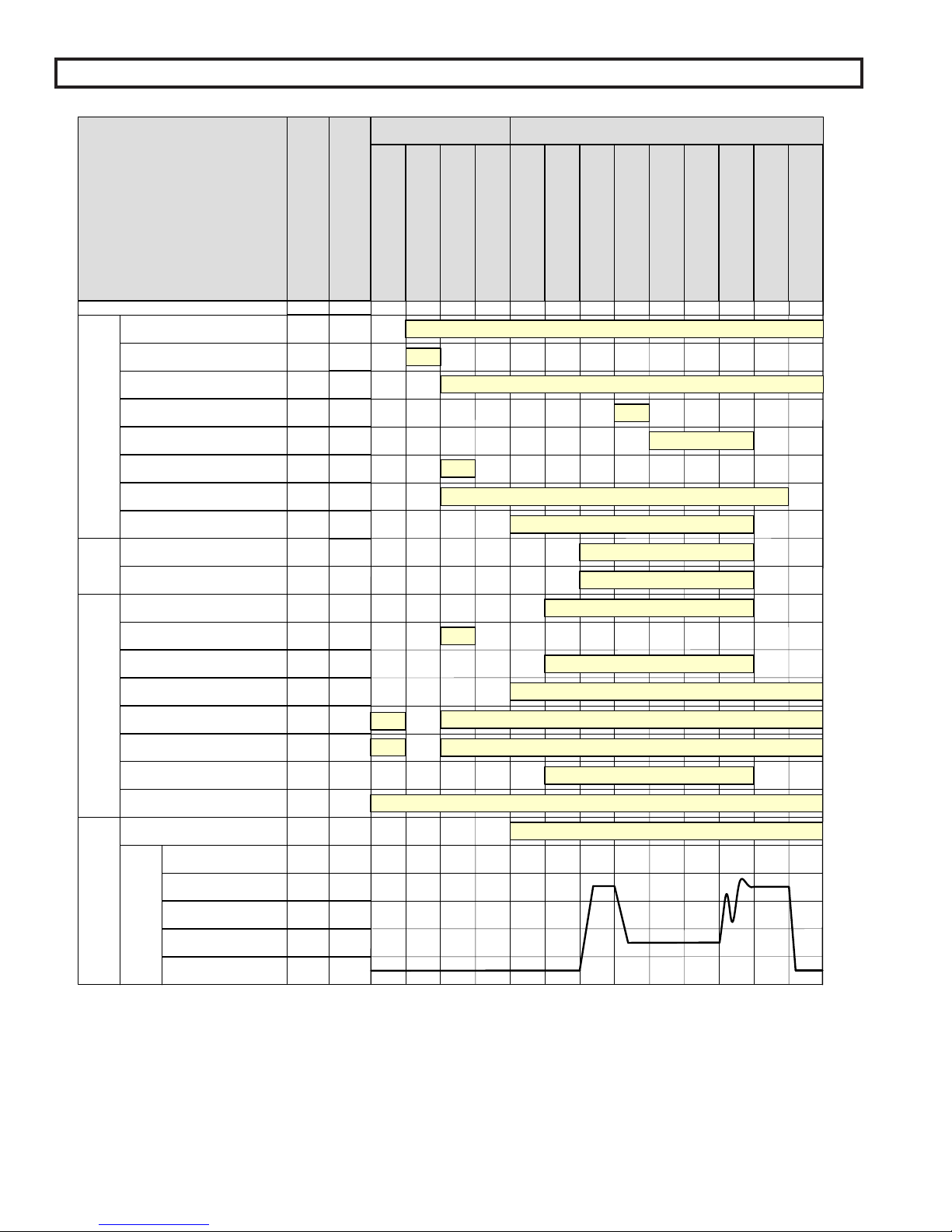
VI. Boiler Operational Sequence
Product Features
Boiler Sequence
Start/Stop Sequence StatesPre-Sequence States
BOILER STATE
LCD Displa y
Boiler Disable or Remote On/Off
Warm Weather Shutdown Setpoint
Domestic Hot Water Priority
System Pump Feedback
(LC, OO, WF , GP and HL inputs)
Limits
Inp uts
(Combustion Air Flow (CA Input))
(Manual Reset Required)
Parame ter / Notes
Outdoor Air Temp >
Low Fire Hold
Fuel Valve Energized
Flame Safeguard Alarm
Call For Heat
Recycling Li mits
Non-Recyclin g Limi ts
Call For Heat Relay
Lockout Indi cator
Spare Output
Terminal Number
RO
O+,O-
DP
SI
CS
AL
SI
R+,R-
OR
BO,BC
LC , OO ,WF,
GP ,H L
CA
CH
LO
VI
-
44 ,30 ,
75
20 ,74
9
-
-
9
70 ,71 ,
72
8,27,
28
-
-
-
-
Parameter/Note
Boiler Disable
Warm Weather
Sh ut do wn
Lockout
b &ca aa
Pump P urg e
Standby
Purge / Pilot Ignition
Limit Hold
-3/d - - -53 4/d
-
Main Ignition
Low Fire / Ignition
Low Fire Hold
Boiler Running
Pump Cooldown
Fan Post Purge
54/d
Boiler Enable/Disable On
Domestic Hot Water Demand Monitored
System Pump Feedback Monitored
Call For Heat
Recycling Limits Made
Non-Recycling Limits Made
Call For Heat Relay On
Spare Output On
Boiler Pump
System Pump
Relay Outputs Interlock Inputs
System Pump Backup Pump
Combustion Air Damper
System Ala rm
Mixing Valve Output
MS,MR
Blower High Speed
Purge %
Modulation
Firing Rate
Modulation Outputs
Low Fire %
Blower 0 Volts
BP
SP
SO
SO
SO
V+,V-,
P+,P -
V+,V-,
P+,P -
V+,V-,
P+,P -
V+,V-,
P+,P -
V+,V-,
P+,P -
2,30
25 ,30
10
10 ,27 /
e
10
6,79,
80
49
52
-
9,51/f
50
Boiler Pump On
System Pump On
Starts in response to System Pump Feedback Input SI
Combustion Air Damper Open
Alarm Status is Monitored
Modulate
Notes
a. Boiler Pump is “On” when the Boiler Pump is set to “On Always” or the boiler is lead boiler and Boiler Pump is set to “On Lead”.
b. Boiler Pump is "On" when the Boiler Pump is set to "On Always" and WWSD is set to "WWSD of System Pump" or “Off”.
c. System Pump is "On" when the System Pump is set to “yes” and WWSD is set to either "WWSD of Boiler" or "Off".
d. Boiler pump is "On" during Prepurge and Post Purge when Boiler Pump is set to "Purge" or boiler is lead & Boiler Pump is set to “On Lead”.
e. Combustion Air Damper Spare Output is maintained “On” for 2 minutes after the Call For Heat is removed.
f. Modulation rate is held at purge % when low fire input is not provided.
46
Page 47
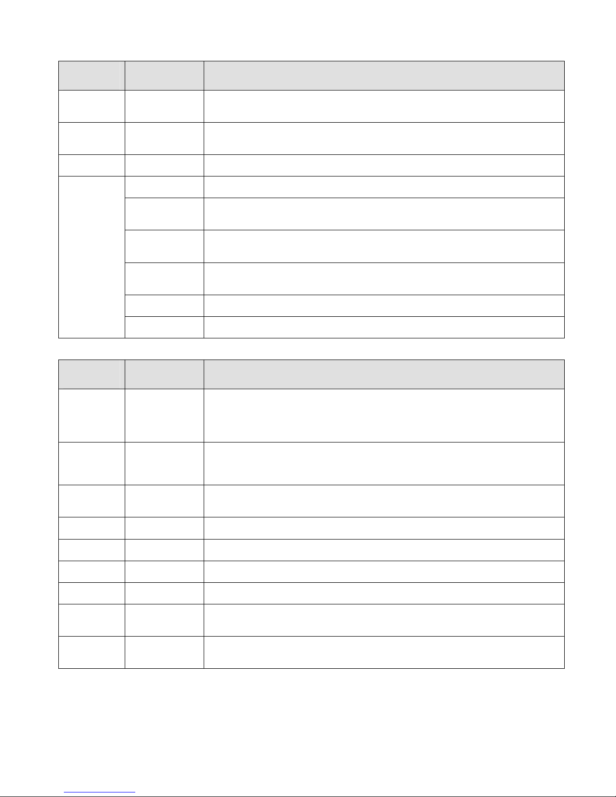
Product Features
Boiler Sequence (Continued)
Pre-Sequence States
BOILER
STATE
LCD Display
Boiler
Disabled
Warm
Weather
Shutdown
Lockout Any Mode
Standby
CONTROL MODE
LCD Display
Any Mode
(Except for
Remote Control)
Any Mode
(Except for
Manual Mode)
Outlet Sensor &
Local SP Mode
Remote Sensor
& Local SP
Mode
Outlet Sensor &
Remote SP
Mode
Remote Sensor
& Remote SP
Mode
Remote Control
Mode
Manual
Operation Mode
Description
Boiler is prevented from starting, Remote On/Off (Enable) (Terminal RO) Input is not
energized.
Boiler is prevented from starting, Warm Weather Shutdown (WWSD) is enabled and
outside air temperature is above the WWSD Setpoint.
Boiler is prevented from starting, Flame Safeguard lockout is present. A Flame
Safeguard manual reset is required.
Control monitors boiler outlet temperature, a Call For Heat is initiated when boiler
outlet temperature is below the Operational Setpoint.
Control monitors Remote System Temperature, a Call For Heat is initiated when
Remote System Temperature is below the Operational Setpoint.
Control monitors boiler outlet temperature, a Call For Heat is initiated when boiler
outlet temperature is below the Remote Setpoint Input (Terminal C+,C- or Modbus
Interface).
Control monitors Remote System Temperature, a Call For Heat is initiated when
Remote System Temperature is below the Remote Setpoint Input (terminal C+,C- or
Modbus Interface).
Control monitors Remote On/Off (Enable) input (Terminal RO or Modbus Interface), a
Call For Heat is initiated when input is energized.
A Call For Heat is initiated when Manual Mode Menu item Boiler On/Off is set to On.
Start/Stop Sequence States
BOILER
STATE
LCD Display
CONTROL MODE
LCD Display
Any Mode
Pump Purge
(Except
Manual Mode)
Limit Hold Any Mode
Purge / Pilot
Ignition
Low Fire /
Ignition
Any Mode
Any Mode
Main Ignition Any Mode
Low Fire
Hold
Boiler
Running
Fan Post
Purge
Pump
Cooldown
Any Mode The modulation output is held at the Low Fire for the Low Fire Hold time.
Any Mode
Any Mode
Any Mode
Description
Once a Call For Heat is initiated and Boiler Pump Purge is selected, the pump output
is energized until the Pump Prepurge Time is complete. If the Call For Heat condition
still exists at the end of the Prepurge Time (the temperature of the water at the sensor
may rise with boiler water flowing passed it) the pump will continue to operate and the
Call For Heat Relay is energized.
Power is applied to the safety limit string. If any limits does not pass power (is not
energized), the alarm LED and LCD display shows the reason the start sequence is
on Hold. Refer to Trouble shooting section for explanation of individual lockout and
alarm messages.
After the limit string passes power, the fan is started, the modulation output is set to
Purge Rate. When the purge period is complete, the flame safeguard sequences on
the ignition transformer and pilot.
When the Spare Input Low Fire is selected, modulation output is set to the Low Fire
Speed when the Spare Input is energized.
The main gas valve input is energized and the modulation output is held constant for
an ignition stabilization period.
When this Low Fire Hold time is complete, the modulation output is released to
modulate.
When water temperature is above setpoint, there is a Flame Safeguard or Limit fault,
the Call For Heat is ended and the modulating output is set to Purge Rate for the Post
Purge Time.
When Boiler Pump Purge is selected, the boiler pump remains “on” until the boiler
outlet temperature is less than the Post Purge Delta (default is 5 F) above the Boiler
Inlet Temperature.
47
Page 48
VII. Service/Maintenance
GENERAL GUIDELINES
1. A thorough and complete boiler inspection and check must be conducted a minimum of one (1) time per year.
2. Follow any checks and/or inspections that may be required as specied in the component manufacturer's
instruction manuals.
3. Repair or replace any defective compontents immediately.
4. The following service procedures are required for proper and safe boiler operation.
DANGER
This boiler uses ammable gas, high voltage electricity, moving parts, and very hot water under high
pressure. Assure that all gas and electric power supplies are off and that the water temperature is cool
before attempting any disassembly or service.
More than one gas shut-off valve and electrical disconnect switch are used on the boiler. Assure that all
gas valves and electrical disconnect switches are off before attempting any disassembly or service.
Do not attempt any service work if gas is present in the air in the vicinity of the boiler.
Never modify, remove or tamper with any control device.
WARNING
This boiler must only be serviced and repaired by skilled and experienced service technicians.
If any controls are replaced, they must be replaced with identical models.
Read, understand and follow all the instructions and warnings contained in all the sections of this
manual.
If any electrical wires are disconnected during service, clearly label the wires and ensure that the wires
are reconnected properly.
Never jump out or bypass any safety or operating control or component of this boiler.
Read, understand and follow all the instructions and warnings contained in ALL of the component
instruction manuals.
Assure that all safety and operating controls and components are operating properly before placing the
boiler back in service.
The service instructions contained in this manual are in addition to the instructions provided by the
manufacturer of the boiler components. Follow component manufacturer’s instructions. Component
manufacturer’s instructions were provided with the boiler. Contact component manufacturer for
replacement if instructions are missing. Do not install, start up, operate, maintain or service this
boiler without reading and understanding all of the component instructions. Do not allow the boiler
to operate with altered, disconnected or jumpered components. Only use replacement components
identical to those originally supplied by Thermal Solutions.
USE caution when servicing components behind upper front jacket panel. Filter/mounting bracket may
cause head injury.
Label all wires prior to disconnection when servicing controls. Wiring errors can cause improper and
dangerous operation.
Verify proper operation after servicing.
CAUTION
48
Page 49
A. SAFETY AND OPERATING CONTROLS. OPERATION AND SHUT DOWN
Component Function
Circuit Board Fuse
Power Switch
Operating Aquastat
Manual Reset High
Limit Aquastat
Flow Switch
Pressure (Safety)
Relief Valve
Mixer Fuseable Link
If the power draw of the control circuit exceeds approximately 5 amps, the circuit board
fuse trips and prevents the boiler from operating until the fuse is replaced.
If this switch is in the off position, power is interrupted to the control circuit of the boiler,
which prevents the boiler from operating. If the switch is in the on position, power is
supplied to the control circuit.
If the boiler water temperature exceeds the adjustable set point, power is interrupted to
the control circuit of the boiler, which prevents the boiler from operating. When the boiler
water temperature drops below the set point minus the adjustable differential setting, power
is again supplied to the control circuit.
If the boiler water temperature exceeds the adjustable set point, power is interrupted to the
control circuit of the boiler, which prevents the boiler from operating. Power is interrupted
until the control is manually reset by pressing the control’s reset button. When the button
is depressed, power will again be supplied to the control circuit.
If the water ow through the boiler drops below the xed ow rate required to move the
control’s paddle enough to close the controls contacts, power is interrupted to the control
circuit, which prevents the boiler from operating. When the water ow rate is increased,
the paddle closes the control’s contacts and power is supplied to the control circuit.
If the pressure inside the appliance exceeds the xed set point, the valve opens
mechanically and discharges water. The valve remains open until the pressure inside the
appliance drops below the set point.
If the temperature in the interior of the burner exceeds the xed set point, The contacts of
the switch open and power is interrupted to the control circuit, which prevents the boiler
from operating. Power is interrupted until the switch is replaced.
Vestibule Fuseable
Link
High and Low Gas
Pressure Switches
Combustion Air Flow
Switch
Flame Safeguard
Control
Variable Frequency
Drive (VFD)
Thermal Solutions
Boiler Control™
(TSBC)™
If the temperature in the interior of the vestibule enclosure exceeds the xed set point, the
contacts of the switch open and power is interrupted to the control circuit, which prevents
the boiler from operating. Power is interrupted until the switch is replaced.
If the gas pressure reaches a point below the adjustable set point, or above the adjustable
set point, the contacts of the switch open and power is interrupted to the control circuit,
which prevents the boiler from operating. Power is interrupted until gas pressure is
between the high and low set points and the control is manually reset by moving the switch
to the reset position. The switches will not reset until the gas pressure is within the set
point parameters.
If the differential air pressure drops below the xed set point, the contacts of the switch
open and power is interrupted to the control circuit, which prevents the boiler from
operating. Power is interrupted until air ow increases so that the contacts close.
Refer to the manual supplied with the boiler.
The variable frequency drive’s primary function is to vary the rotational speed of the blower
fan based on the air requirements of the boiler combustion process. The VFD responds to
a 0-10 VDC signal from the TSBC.
The Thermal Solutions Boiler Control™ (TSBC™) is a complete boiler and automation
system. It provides advanced boiler modulation control, operating control, diagnostics,
multiple boiler lead lag and auxiliary device control. Refer to the TSBC manual shipped
with the boiler to learn more about these features and functions.
49
Page 50
B. TROUBLESHOOTING GUIDE
Alarm Messages
Alarm Messages are shown one at a time in priority order. The message closest to the top of this list is displayed rst.
Following messages are not shown until the higher priority message has cleared. All alarm messages are also stored
in the Fault History.
LCD Display
Alarm Message
Low Water Level
Off Switch Turn Burner Switch On
Low Water Flow
Fuel Limit
High Temp Limit
Low Air Flow
FSG Fault
Outlet Temp Fail
Inlet Temp Fail
OA Temp Fail
Remote Temp Fail
Recommended
Action
Manually Reset the Low
Water Cutoff
Ensure Boiler Pump is
Running and Boiler
Water Flow is
Unobstructed
Manually Reset the Fuel
Pressure Switch
Manually Reset the
High Temperature
Aquastat
Check Combustion Air
Blower and Air
Pressure Switch
Settings and Wiring
Manually Reset
Required, Refer to
Flame Safeguard
Manual
Corrective Actions
Check Wiring and
Sensor
Check Wiring and
Sensor
Check Wiring and
Sensor
Check Wiring and
Sensor
Explanation
Low Water Cutoff Switch
When this option is congured and an instrument is installed, the manual reset
low water safety relay is preventing the boiler from starting. If terminal (LC) does
not receive power and the Call For Heat output (CH) is powered, the “Low Water
Level” Message is displayed.
Burner Switch is Off
Control switch is in the OFF position and is preventing the boiler from starting. If
terminal (OO) does not receive power and the Call For Heat output (CH) is powered the “OFF Switch” Message is displayed.
Low Water Flow Switch
Low water ow is preventing the boiler from starting. If terminal (WF) does not
receive power and the Call For Heat output (CH) is powered, the “Low Water
Flow” Message is displayed.
Low or High Gas Pressure Switch
The low or high gas pressure switch is preventing the boiler from starting. If
terminal (GP) does not receive power and the Call For Heat output (CH) is
powered, the “Fuel Limit” Message is displayed.
High Limit Temperature
The high temperature limit (HL) (and operational temperature limit when
provided) aquastat is preventing a boiler start. If terminal (HL) does not receive
power and the Call For Heat output (CH) is powered, the “High Temp Limit”
Message is displayed.
Low Air Flow or Blocked Vent Switch Not Made
The air ow (and blocked vent switch when installed) is preventing a boiler start.
If terminal (CA) does not receive power and the Call For Heat output (CH) is
powered, the “Low Air Flow” Message is displayed.
Flame Safeguard Fault
The Flame Safeguard is preventing a boiler start. If terminal (AL) receives power
at any time, the “Flame Failure” Message is displayed.
Boiler Outlet Temperature Sensor Fail
The boiler outlet temperature sensor is not connected or is reading above or
below a valid range. When the boiler outlet sensor fails and the Outlet Sensor
mode was selected, the control will transfer to Lost Sensor Blind Mode.
Boiler Inlet Temperature Sensor Fail
The boiler inlet temperature sensor is not connected or is reading above or below
a valid range. When the boiler inlet sensor fails, the mixing valve output will drive
to 0% and low temperature alarm and maximum water differential (boiler outlet
minus boiler inlet) temperature hold are disabled.
Outside Air Temperature Sensor Fail
The outside air sensor is congured and is not connected or is reading above or
below a valid range. When the outside air sensor fails, the warm weather shutdown (WWSD) and outside air reset control logics are disabled.
Remote System Temperature Sensor Fail
The remote system temperature sensor is congured and is not connected or is
reading above or below a valid range. If Remote System Temperature Sensor
mode was selected, the control will transfer to Boiler Outlet Sensor Mode.
50
Page 51

TROUBLESHOOTING GUIDE (CONTINUED)
LCD Display
Alarm Message
Remote Input Fail
Comm Failure
Recommended
Action
Check Wiring and
Remote System
Conrm each boiler has
a unique address
Check Wiring and
Remote System
Explanation
Remote Control Input Fail
The Remote Control Input is congured and is not connected or is above or below a valid range. When the remote control input fails, the following control mode
changes are taken automatically:
Selected Modes Resulting Control Mode
Remote Mod Outlet Sensor and Local Setpoint
Remote Mod & Remote Sensor Remote Sensor and Local Setpoint
Remote SP Outlet Sensor and Local Setpoint
Remote SP & Remote Sensor Remote Sensor and Local Setpoint
Communication Failure
The Modbus or Peer-To-Peer network has failed. When the Modbus network fails
the following control mode changes are taken automatically:
Selected Modes Resulting Control Mode
Modbus Mod Outlet Sensor and Local Setpoint
Modbus Mod & Remote Sensor Remote Sensor and Local Setpoint
Modbus SP Outlet Sensor and Local Setpoint
Modbus SP & Remote Sensor Remote Sensor and Local Setpoint
After a Modus communication failure, the ‘Comm Failure’ alarm is not cleared
until communication is restored and successfully writes to both the Remote On
/ Off Modbus Command (00004) and Remote Firing Rate or Remote Setpoint
(40006) points have been completed, power is cycled or the protocol parameter is
changed to Peer-To-Peer and then back to Modbus.
Low Inlet Temp
Memory Failure
Check return water
temperature. Consider
system or operational
changes to avoid low
temperature events
Check wiring and
sensor
Call Factory Reset
all memories in
System menu:
Clr BIT History
Clr Alarm Hist
Clr Run Time Cnt
Clr Cycle Cnt
Factory Defaults
(Factory Level
Password is required)
When a Peer-To-Peer network has failed the boilers begin operation as stand
alone boilers using the selected parameters.
After a Peer-To-Peer communication failure the ‘Comm Failure’ alarm is not
cleared until communication is restored and the boiler rejoins a network with at
least one other boiler, power is cycled or the protocol parameter is changed to
Modbus and then back to Peer-To-Peer.
Low Boiler Inlet Temperature
If the boiler inlet temperature is below the Low boiler inlet temperature setpoint,
the “Low Inlet Temp” Message is displayed and the boiler inlet temperature
history is stored.
Memory Failure
New software has been installed in the Thermal Solutions Boiler Control (TSBC)
or a power interruption has caused a memory failure. The Call For Heat will be
prevented until the condition is cleared.
51
Page 52

C. PERIODIC MAINTENANCE RECOMMENDED CHECK LIST
Frequency Component/Item Recommended Test
Inspect the area to assure proper clearance to combustible materials,
gasoline, and other ammable vapors and liquids.
Make visual inspection and record readings.
Check combustion properties as specied in section VII, part D.
Make visual inspection of burner ame as stated in section VII, part D.
Test low draft, fan, air pressure, and damper position interlocks
according to instructions if so equipped.
Make visual inspection, check ame signal strength; log.
Read and log ame signal meter, read for both pilot and main ames.
Close manual fuel supply for (1) pilot, (2) main fuel cock, and/or
valve(s); check safety shutdown timing. Refer to section VII, Part D.
Check ring rate control, place TSBC™ in manual mode and check
high and low ring settings for proper operation.
Open limit switch and make aural and visual check; check valve
position indicators and check fuel meters if so tted.
Test low-water fuel cutoff device and alarm according to
manufacturer’s instructions.
Conrm that components are gas tight and free from obstructions to
ow.
Test high and low gas pressure interlocks.
Test condition of water, correct condition as needed.
Recalibrate all indicating and recording gauges.
Check components.
Check drain tubes have liquid in trap and condensate is properly
directed.
Check air lter as specied in section VII, Part D.
Check piping and wiring of all interlocks and shut off valves if so
equipped.
Maintain according to manufacturers' instructions.
Conrm that components are gas tight and free from obstructions to
ow.
Check combustion properties as specied in section IV, Part I, Step 5.
Conduct pilot turndown test according to manufacturer’s instructions.
This test is required annually and after any adjustments to ame
scanner mount or pilot burner.
Check all coils and diaphragms; test other operating parts of all safety
shutoff and control valves.
Perform leakage test on pilot and main gas and/or oil fuel valves, in
accordance with instructions.
Test purge timing according to manufacturer’s instructions.
Replace
Remove lower front jacket panel and check for any signs of corrosion
and leaks.
Check and clean if dirty. Refer to section VII, Part D.
Test proper operation.
Test proper operation. Refer to section VII, Part D.
Recondition or replace.
Test safety relief valves in accordance with ASME Boiler and Pressure
Vessel Code, Sections VI and VII.
Daily
Maintenance
Weekly
Maintenance
Monthly
Maintenance
Semi-Annual
Maintenance
Annual
Maintenance
As-Required
Boiler surroundings
Gauges, monitors, and indicators
Combustion Properties
Burner ame
Low Draft, fan air pressure, and damper
position interlocks
Igniter
Flame signal strength
Flame failure detection system
Firing rate control
Pilot and/or main fuel valves
Low-water fuel cutoff
Flue, vent, stack, condensate drains,
and outlet dampers
Gas pressure interlocks
Water condition
Gauges, monitors, and indicators
Flame failure detection system
Condensate drain tubes
Air lter
Interlocks and valves
Circulators and system pumps
Flue, vent, stack, or outlet dampers
Combustion Properties
Flame failure detection system
Pilot and/or main fuel valves
Pilot and/or main fuel valves
Flame safeguard
Air Filter
Boiler trim
Secondary Heat Exchanger
High limit and operating temp. controls
Mixing Valve
Low-water fuel cutoff
Safety relief valves
52
Page 53

D. INSPECTION AND CLEANING PROCEDURES
Daily Boiler Inspection & Check
1. Inspect the area to assure proper clearance from
combustible materials, gasoline, and other ammable
vapors and liquids.
2. Observe burner color. See "Pilot and Main Flame"
instructions later in this section
3. Check ame control for proper operation and shutdown.
4. Check vent and air intake piping for any obstructions.
5. Check for any water leaks in the entire boiler assembly.
a.) For leaks in the boiler secondary Victaulic® piping:
i) Disassemble the leaking coupling
ii) Clean and lubricate the gasket. Clean all surfaces
mating to the gaskets prior to reassembly.
iii) See www.victaulic.com for specic details about
the QuickVic® style 107 couplings.
NOTICE
Victaulic® brand water-based Vic-Lube shall be
used to lubricate all coupling and ange gaskets
prior to reassembly. Oil-based lubricants shall
not be used.
6. Check for any gas leaks.
7. Check condensate drains for any obstructions.
8. Clean any debris or trash from area.
9. Check the low dra, fan, air pressure, and damper position
interlocks, according to the manufacturer's instructions,
if so equipped.
10. Check gauges, monitors, and indicators to assure they are
functioning properly.
11. Log that the above maintenance was completed in an
appliance log. Maintain log near appliance location.
Weekly Boiler Inspection & Check
1. Check ame strength for both pilot and main ames; log.
2. Check ignitor.
3. Check operation of the ame failure detection system for
both pilot and main ame.
4. Check ring rate control for proper operation.
5. Check pilot and main fuel valves:
Open limit switch and make aural and visual inspection,
check valve position indicators and fuel meters, if provided.
6. Check the low water cuto device and alarm according
to the manufacturer's instructions.
Monthly Safety and Operating Control Checks
1. Check proper operation of all boiler system safety and
operating controls including ame safeguard.
2. Check proper operation safety relief valve.
3 Check condition of water (pH, alkalinity, hardness).
Correct water condition as needed.
4. Check carbon monoxide level in ue products.
5. Check venting/air intake and condensate drain tubes for
obstructions.
6. Repair or replace any inoperative or damaged components.
7. Low water cuto, oat type (if so equipped):
Monthly blowo. During the heating season, if an
external oat type low water cuto is above the boiler,
the blowo valve should be opened once per month (use
greater frequency where conditions warrant), to ush out
the sediment chamber so the device will be free to
function properly.
8. Inspect and replace air lter as needed.
9. Check high and low gas pressure switch interlocks.
10. Log service procedure in appliance log.
Semi-Annual "Tune-Up"
1. Inspect condensate drain tubes for deterioration,
cracking, etc.
2. Inspect air intake and exhaust pipes for leaks, deterioration,
scale, etc.
3. Measure fuel input, oxygen and carbon monoxide in ue
products.
4. Adjust burner to obtain values noted in retest report.
5. Complete safety and operating control checks.
6. Repair or replace any inoperative or damaged components.
7. Log service procedures in water appliance log.
Annual Boiler Inspection and Check
1. Replace air lter.
2. Remove and inspect pilot assembly.
3. Remove lower front jacket panel and check for any signs
of corrosion and leaks.
4. Remove pipe plugs in header and inspect inside of copper
tubes and header.
5. Flush boiler and mechanically remove any scale.
6. Remove, inspect, and clean water ow switch and low
water cutos.
7. Complete "tune-up" procedures (See previous instructions).
8. Log service procedures in appliance log.
9. Repair or replace any inoperative or damaged components.
10. Vent/Air Intake System. Inspect for obstructions, soot
accumulation, proper support, and deterioration of pipe,
ttings, and joints.
a.) Clean terminal screens. Terminals must be
free of obstruction, undamaged, with screens
securely in place.
b.) Terminal and wall thimbles (if used) must be
weathertight.
c.) Pipe must be full round shape, and show no
damage from impact or excessive temperature.
d.) Pipe must be supported at minimum (5) foot
intervals and must not sag.
e.) All vent joints must be secure and watertight.
f.) Horizontal vent tee drain or vertical vent tee
drain (if used) must have minimum 6 inch trap and
allow condensate to ow freely.
To clean:
i.) Disconnect drain tube from drain tting
ii.) Flush drain tube with water. Fill trap with water.
iii) Securely fasten drain tube to drain tting,
providing gas-tight and watertight seal.
g.) If pipe must be disassembled for removal of
obstructions or resealing of joint, see VENTING
section of the manual.
11. Low Water Cuto (if so equipped)
a.) Float type low water cutos should be dismantled
annually by qualiied personnel, to the extent necessary
to ensure freedom from obstructions and proper
functioning of the working parts.
i.) Inspect connecting lines to boiler for accumulation
of mud, scale, etc. and clean as required.
53
Page 54

ii.) Examine all visible wiring for brittle or
worn insulation and make sure electrical
contacts are clean and that they function
properly. Give special attention to solder
joints on bellows and oat when this type of
control is used.
iii.) Check oat for evidence of collapse and
check mercury bulb (where applicable) for
mercury separation or discoloration.
b.) Probe Type: Probe type LWCO should be
removed once a year and cleaned of any dirt
accumulations to assure proper operation.
Do not attempt to repair mechanisms in
the eld. Complete replacement
mechanisms, including necessary gaskets and
installation instructions, are available from the
manufacturer.
12. Verify proper operation aer servicing.
Air Filter
A. Perform a visual inspection of air lter and replace
as necessary.
1. Remove upper front panel.
2. Remove tube from nipple on lter assembly.
3. Remove wing nut.
4. Remove lter assembly from boiler. For the
EVCA-3000: to facilitate assembly removal, loosen
the two top screws on the lower front panel and
lean the lower front panel forward. Remove the
blower lter front plate, if necessary.
5. Remove foam prelter and wash with soap and
water.
6. Replace primary lter as necessary.
Pilot and Main Flame
A. Perform a visual inspection of pilot burner ame.
1. Refer to the ame safeguard instruction manual
and conduct a pilot turndown test.
2. Observe pilot operation and record pilot signal.
Flame should be steady medium hard blue.
B. Pilot cleaning and maintenance
1. Shut o gas supply and disconnect electrical
service.
2. Disconnect scanner, ignition electrode, loosen
and remove pilot gas line and combustion air
line from fan.
3. Remove mounting fasteners and pull pilot
assembly from heat exchanger.
4. Examine pilot electrode and set gaps to 1/8" if
needed. Clean as required.
5. Reassemble in reverse order using a new gasket
available from ermal Solutions.
C. Perform a visual inspection of main burner ame
1. Observe main ame and record ame signal.
Flame color should be steady deep orange in color
with dark blue checkerboard pattern throughout.
2. Main burner requires no cleaning or annual
maintenance.
Check Combustion and Safety Controls
A. Check ame failure detection system with system
operating.
1. Pilot
a.) Refer to the ame safeguard instruction
manual.
b.) Manually close pilot fuel supply and verify
lock out of primary control.
2. Main Flame
a.) Refer to the ame safeguard instruction
manual.
b.) Close manual main fuel shut-o valve and
CAUTION
Do not attempt to remove or service burner.
Damage to the burner may result. Consult
boiler manufacturer.
Secondary Heat Exchanger
A. Remove vent pipe from stack adapter
B. See Figure 18. Use ashlight to inspect the ns of
the heat exchanger through stack adapter opening.
C. If excessive deposits are found, refer to the
following section for cleaning instructions.
D. Re-install vent on stack adapter.
Cleaning Secondary Heat Exchanger for EVCA
Units:
A. Remove vent pipe from stack adapter.
B. See Figure 18. Using the opening in the stack
adapter (1) as a point of entry, remove foreign
matter from the secondary heat exchanger (2) by
sprayng an industrial coil cleaner as specied by
the manufacturer.
C. Reinstall vent on stack adapter.
Mixing Valve:
A. Set TSBC to control the mixing valve manually.
B. Stroke the valve from 0-100%, periodically
stopping to check for proper positioning and valve
seizures.
C. Troubleshoot control signals and valve actuator for
positioning errors.
D. Replace valve body if seizure occurs.
1. When removing/servicing the mixing valve,
never li by the mixing valve actuator. Li the
valve body.
54
Page 55
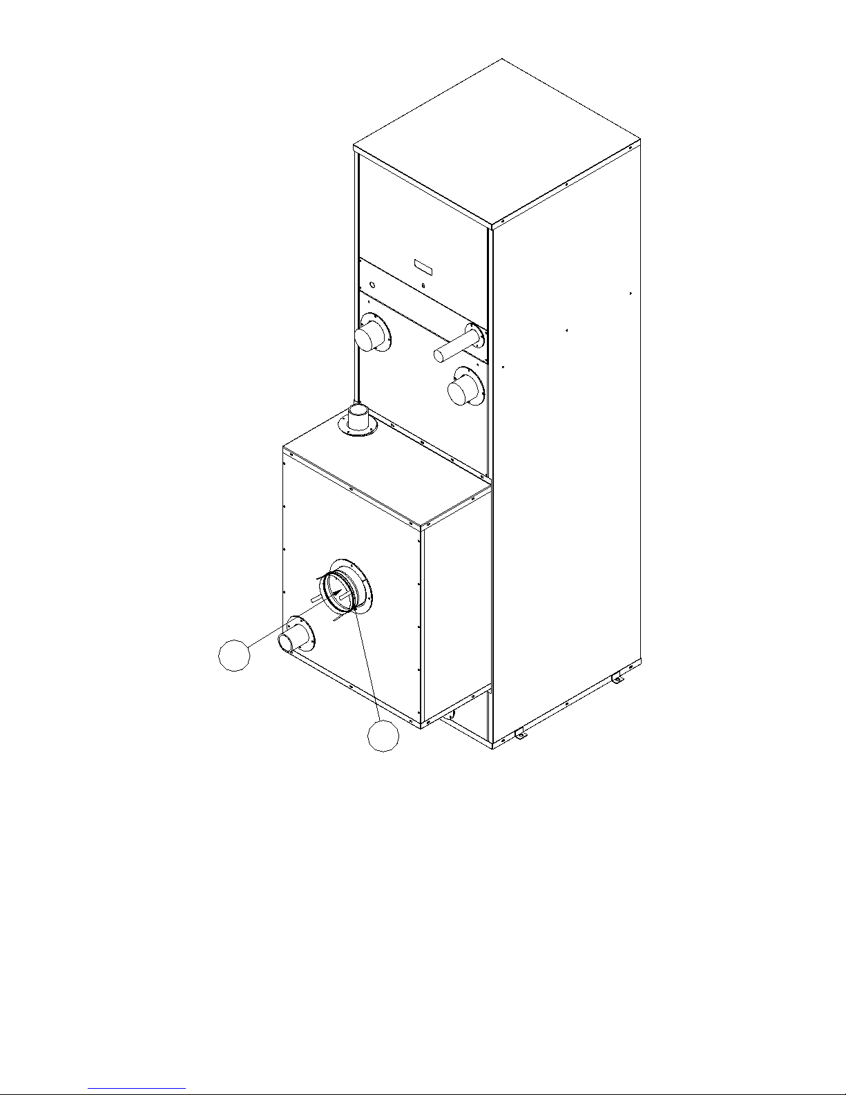
2
1
Figure 18: Cleaning Secondary Heat Exchanger
55
Page 56

This page intentionally left blank
56
Page 57

VIII. Repair Parts
EVCA Series repair parts can be ordered through your nearest ermal Solutions Representative for delivery from Lancaster, PA.
e Representatives can also advise as to the availability of product and repair parts from local sources.
Contact ermal Solutions for your Representative at:
ermal Solutions Products LLC
1175 Manheim Pike
Lancaster, Pennsylvania 17601
Telephone (717) 239-7642
Fax (877) 501-5212 (toll free)
www.thermalsolutions.com
WARNING
The repair parts noted in this section are for a standard EVCA Series boiler. Different contents and
components may have been supplied due to the request of the equipment end user. Consult Thermal
Solutions for repair parts on non-standard controls and components.
57
Page 58
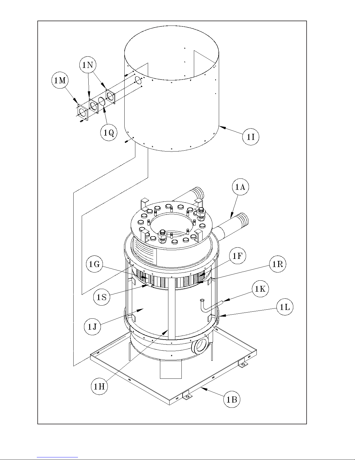
Figure 19: Boiler Combustion Chamber
58
Page 59
BOILER COMBUSTION CHAMBER
Key
No.
Description
EVCA-750 EVCA-1000 EVCA-1500 EVCA-2000
1. COMBUSTION CHAMBER ASSEMBLY
1A Heat Exchanger
(1)
603EVC07510
1B Base
1F Tube Bafe
1G Sight Tube Bafe
Combustion Pan Sup-
1H
port
Heat Exchanger Wrap-
1I
per
1J Heat Exchanger Bafe
(31)
70356215
(1)
70356223
(4)
603562041
(1)
804EVC2003
(1)
70356236
1K Condensate Drain Tube
1L 1” Fiber Gasket
Sight Glass Lens Re-
1M
tainer
1N Sight Glass Gaskets
(Quantity) Part Number
(1)
603EVC01000
61556024
(31)
70356216
(1)
70356224
(4)
603562051
(1)
804EVC2004
(1)
70356237
(1)
806EVC01
(14 LF)
9206032
603EVC01500
(1)
(31)
70356217
70356225
603562061
804EVC2005
70356238
(1)
7186019
(2)
8206039
(1)
(1)
(4)
(1)
(1)
(1)
6035630061
(31)
70356218
(1)
70356226
(4)
603562071
(1)
804EVC2006
(1)
70356239
8065601
EVCA-
3000
(1)
104057-01
(1)
103078-01
(41)
70356317
(1)
70356320
(6)
60356210
(1)
103081-02
(1)
70356242
(1)
(19.5)
9206032
1Q Sight Glass Lens
1R Wrapper Banding
1S Banding Buckle
Temperature Probe (not
1T
shown)
8026082
(24 LF)
92466028
80860946
101935-01
(1)
(25.5 LF)
92466028
(4)
(2)
59
Page 60
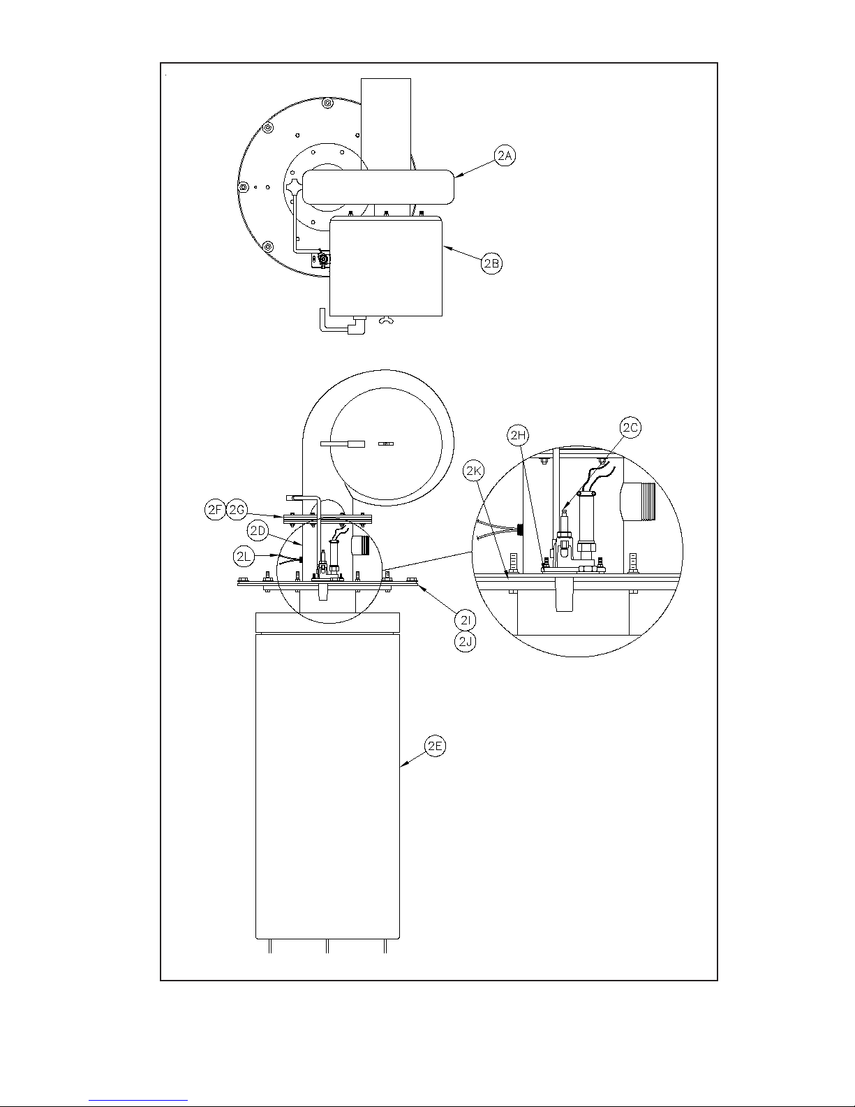
TOP
VIEW
FRONT
VIEW
Figure 20: Burner Assembly
60
Page 61

Key
No.
Description
2. BURNER/ FAN ASSEMBLY
2A Fan (three phase)
2B Air Filter
Pilot Assembly - Natural
2C
-OR- Pilot Assembly -LP
BURNER ASSEMBLIES
(Quantity)
Part Number
EVCA-750 EVCA-1000 EVCA-1500 EVCA-2000 EVCA-3000
81156018
(1)
81156011
(1)
(1)
81156012
See Figure 27
(1)
81156300
(1)
81156101
Mixer Assembly - Natural
2D
Mixer Assembly - LP
2E Burner Element
2F Air Orice Gasket
2G Air Orice
2H Pilot Gasket
2J Burner Gasket
Burner Mounting Flange
2K
Gasket
Burner Thermal Fuse
2L
Assembly
(1)
60256209
(1)
60256213
(1)
TS750CF-
GBNR
80256235
(1)
60256210
(1)
60256214
(1)
TS1000CF-
GBNR
(1)
60256211
60256215
TS1500CF-
GBNR
(2)
8205603
80256236
(1)
82056041
(1)
8205605
(1)
6025601
(1)
(1)
(1)
(1)
(1)
8205608
(1)
60256212
(1)
60256216
(1)
TS2000CF-
GBNR
(1)
80256237
(1)
62156300
(1)
62156300
(1)
TS3000CF-
GBNR
(2)
8205666
N/A
(1)
82056501
(1)
8205665
N/A
61
Page 62
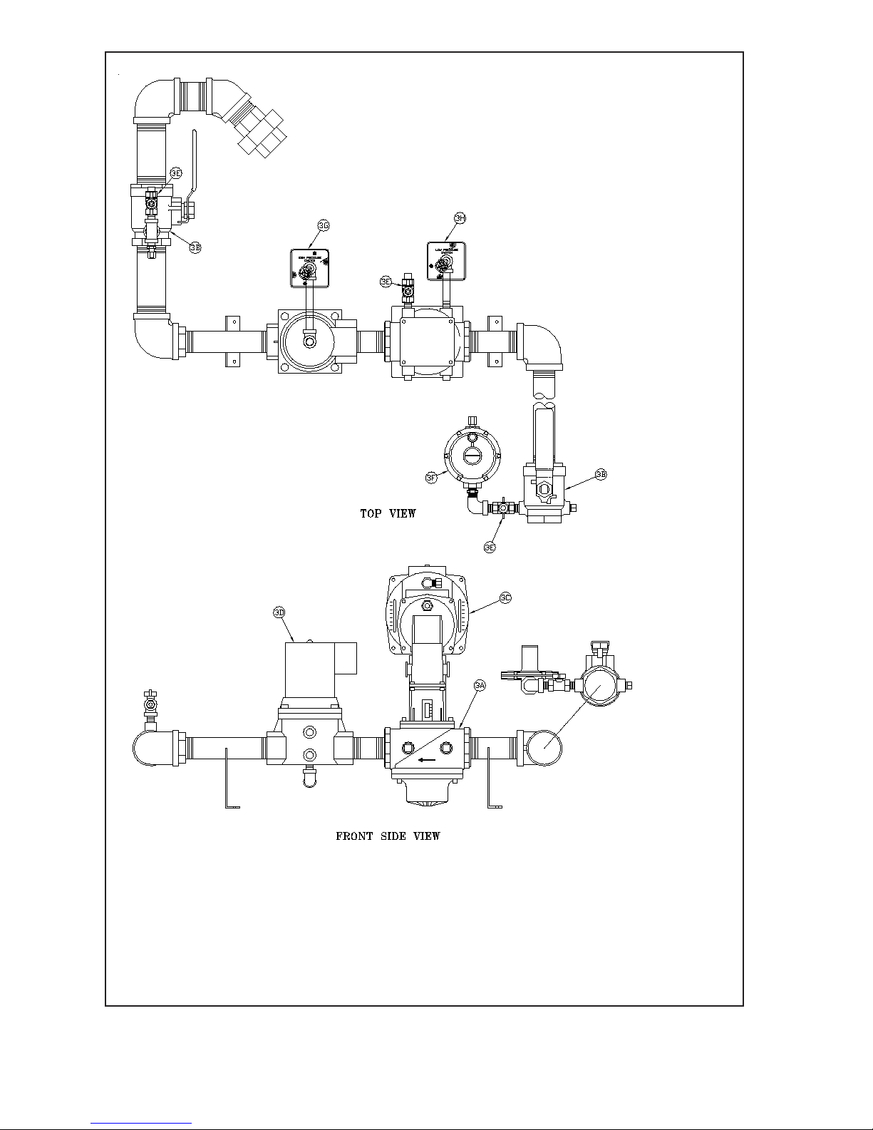
Figure 21a: UL/FM/CSD-1 Main Gas Train Assembly (EVCA-750/2000)
62
Page 63
UL/FM/CSD-1 GAS TRAIN - MAIN AND PILOT
Key
No.
Description
EVCA-750 EVCA-1000 EVCA-1500 EVCA-2000
3. MAIN AND PILOT GAS TRAIN (UL/FM/CSD-1)
Main Gas Valve Body, 1"
NPT
(1)
816634041
3A
Main Gas Valve Body, 1½"
NPT
Manual Gas Valve with Pilot
Tapping, 1" NPT
---
(1)
806603055
3B
Manual Gas Valve with Pilot
Tapping, 1½" NPT
Air/Gas Ratio Controller,
3C
Siemen's SKP75
Solenoid Valve
V4295A1031, 1" NPT
(1)
806603053
(1)
81660207
3D
Solenoid Valve
V4295A1056, 1½" NPT
---
3E Manual Gas Cock, ¼"
3F Pilot Gas Regulator
3G High Gas Pressure Switch
3H Low Gas Pressure Switch
(Quantity) Part Number
--- --- ---
(1)
81663404
--- --- ---
(2)
806603053
(1)
81663408
--- --- ---
(1)
81660205
(3)
822758
(1)
822702
(1)
80160333
(1)
80160332
63
Page 64
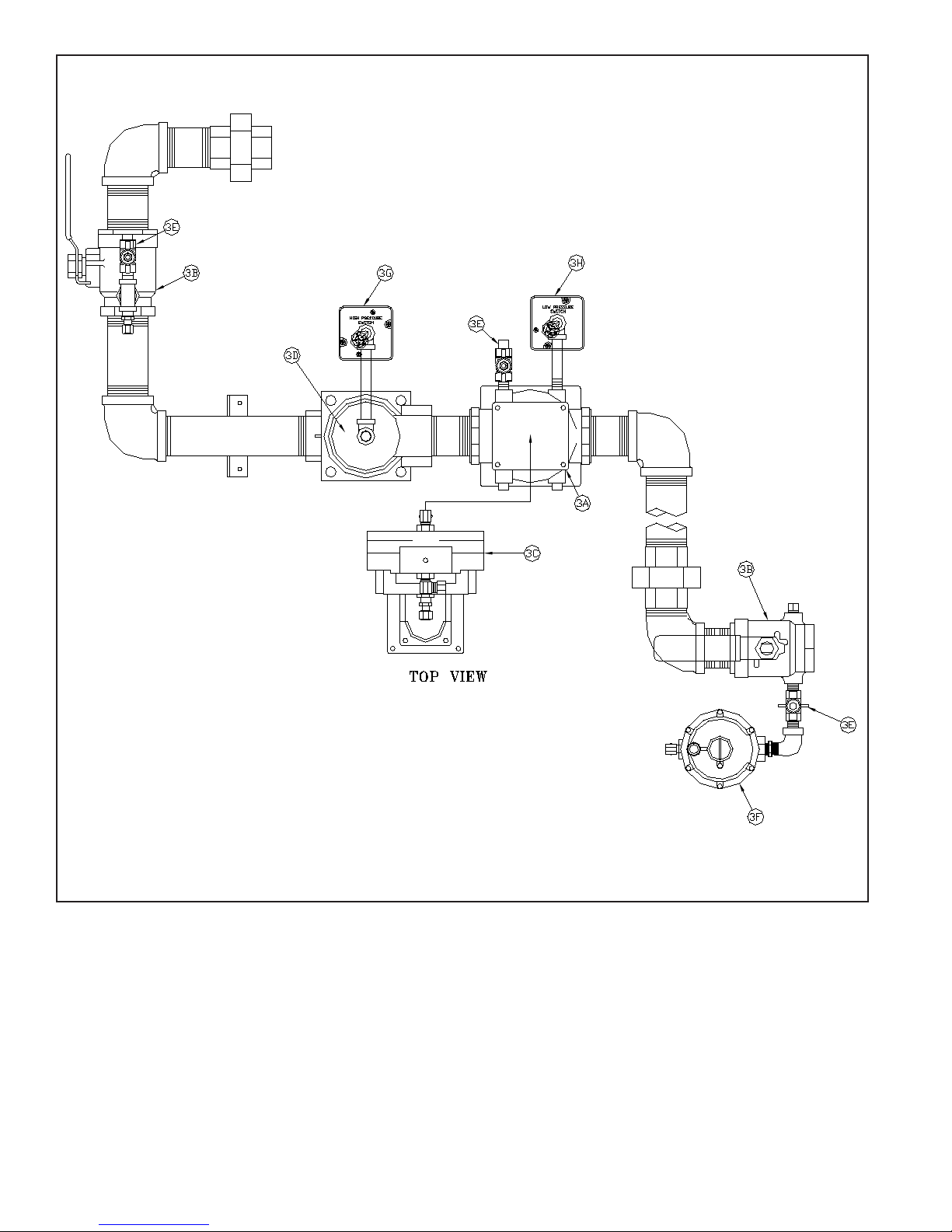
Figure 21b: UL/FM/CSD-1 Main Gas Train Assembly (EVCA-3000)
64
Page 65

UL/FM/CSD-1 Gas Train - Main and Pilot
Key No. Description
Main and Pilot Gas Train (UL/FM/CSD-1)
3A Main Gas Valve Body, 2" NPT
3B
3C
3D
Manual Gas Valve Body with Pilot
Tapping, 2" NPT
Air/Gas Ratio Controller, Siemens
SKP75
Solenoid Valve V4295A1064, 2"
NPT
3E Manual Gas Cock, 1/4"
3F Pilot Gas Regulator
3G High Gas Pressure Switch
3H Low Gas Pressure Switch
(Quantity)
Part Number
EVCA-3000
(1)
816634043
(2)
806604691
(1)
81663408
(1)
816602051
(3)
822758
(1)
822702
(1)
80160333
(1)
80160322
65
Page 66
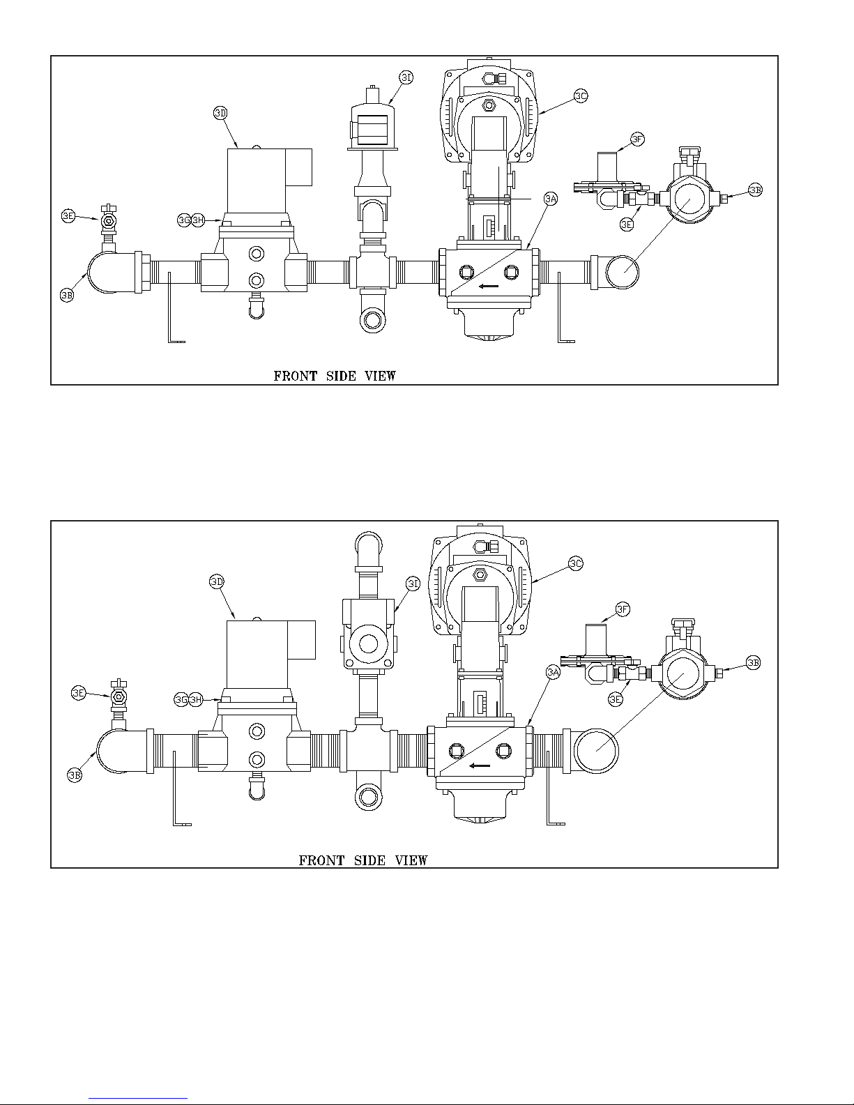
Figure 22a: DB&B Gas Train (750)
Figure 22b: DB&B Gas Train (1000-2000)
66
Page 67
Key
No.
Description
3. MAIN AND PILOT GAS TRAIN
Main Gas Valve Body 1" NPT (1)
3A
Main Gas Valve Body, DBL,
1-1/2" NPT
Manual Gas Valve with Pilot
Tapping, 1" NPT
3B
Manual Gas Valve with Pilot
Tapping, 1-1/2" NPT
DB&B Actuator/Regulator
3C
Ratio Valve, Siemens SKP75
(max 5 PSI)
3D DB&B Solenoid Valve
3E Manual Gas Cock, 1/4"
3F Pilot Gas Regulator
3G High Gas Pressure Switch
3H Low Gas Pressure Switch
3I Normally Open Vent Valve
DB&B – MAIN AND PILOT
(Quantity) Part Number
EVCA-750 EVCA-1000 EVCA-1500 EVCA-2000
816634041
—
(1)
806603055
(1)
806603053
— — —
(1)
81663404
— — —
(2)
806603053
(1)
81663408
(1)
81660207
(1)
81660205
(3)
822758
(1)
822702
(1)
80160333
(1)
80160332
(1)
81660748
67
Page 68
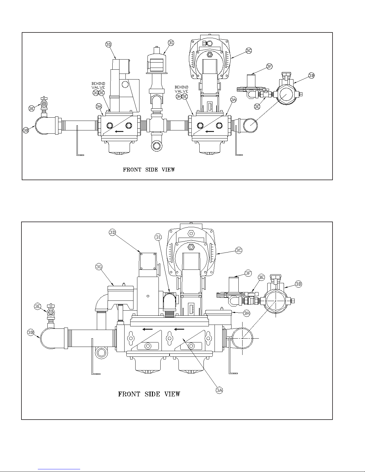
Figure 22c: DB&B w/POC Gas Train (750)
Figure 22d: DB&B w/POC Gas Train (1000-2000)
68
Page 69
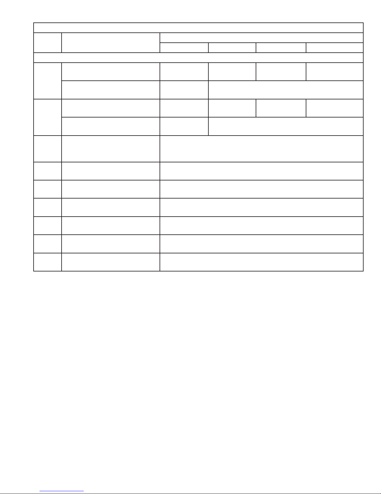
Key
No.
Description
3. MAIN AND PILOT GAS TRAIN
Main Gas Valve Body 1" NPT
3A
Main Gas Valve Body, DBL,
1-1/2" NPT
Manual Gas Valve with Pilot
Tapping, 1" NPT
3B
Manual Gas Valve with Pilot
Tapping, 1-1/2" NPT
DB&B w/POC Actuator/
3C
Regulator Ratio Valve,
Siemens SKP75 (max 5 PSI)
3D
DB&B w/POC Actuator,
Siemens SKP15
3E Manual Gas Cock, 1/4"
3F Pilot Gas Regulator
3G High Gas Pressure Switch
3H Low Gas Pressure Switch
3I Normally Open Vent Valve
DB&B W/POC – MAIN AND PILOT
(Quantity) Part Number
EVCA-750 EVCA-1000 EVCA-1500 EVCA-2000
(2)
816634041
— — —
—
(1)
806603055
— — —
(1)
806603053
81663409
81663407
80160333
80160332
81660748
(1)
81663404
(2)
806603053
(1)
(1)
(3)
822758
(1)
822702
(1)
(1)
(1)
69
Page 70
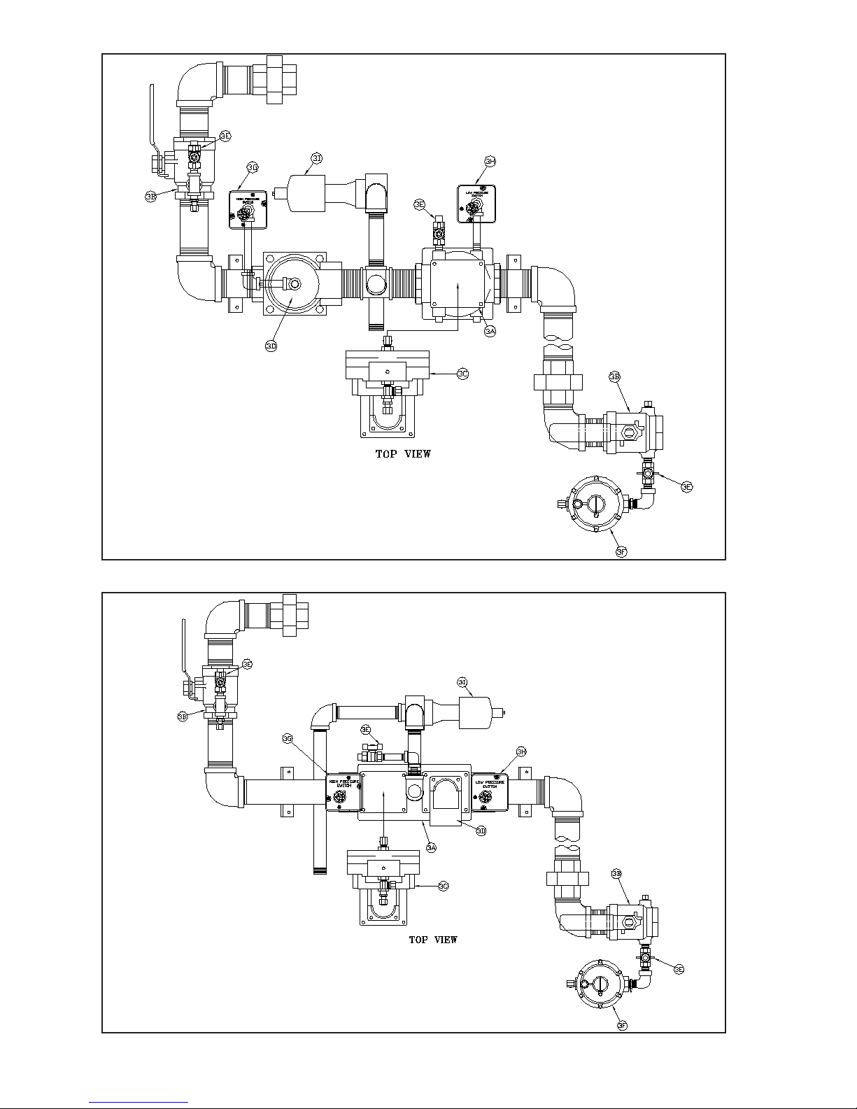
Figure 22e: DB&B Gas Train (EVCA-3000)
Figure 22f: DB&B w/POC Gas Train (EVCA-3000)
70
Page 71
DB&B AND DB&B W/POC -
MAIN AND PILOT
Key
No.
3. MAIN AND PILOT GAS TRAIN
Main Gas Valve Body, DB&B,
2" NPT
3A
Main Gas Valve Body, DB&B
w/POC, 2" NPT
Manual Gas Valve with Pilot
3B
Tapping
DB&B Actuator/Regulator
Ratio Valve, Siemens SKP75
(max 5 psi)
3C
DB&B w/POC Actuator/Regulator Ratio Valve Siemens
SKP75 (max 5 psi)
DB&B Solenoid Gas Valve,
Honeywell
3D
DB&B w/POC Actuator, Siemens SKP15
3E Manual Gas Cock
3F Pilot Gas Regulator
3G High Gas Pressure Switch
3H Low Gas Pressure Switch
3I Normally Open Vent Valve
Description
(Quantity)
Part Number
EVCA-3000
(1)
816634043
(1)
816634051
(2)
80660491
(1)
81663408
(1)
81663409
(1)
8016602051
(1)
81663407
(3)
822758
(1)
822702
(1)
80160333
(1)
80160332
(1)
816607501
71
Page 72
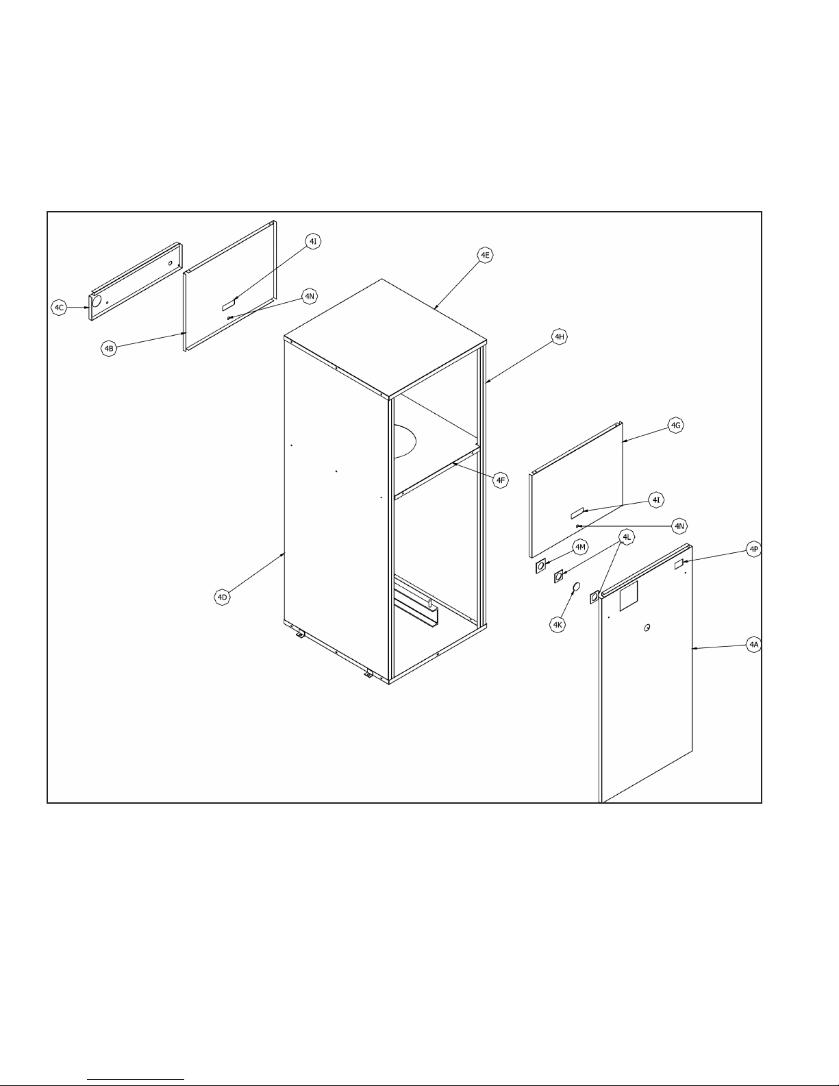
Figure 23: Jacket
72
Page 73
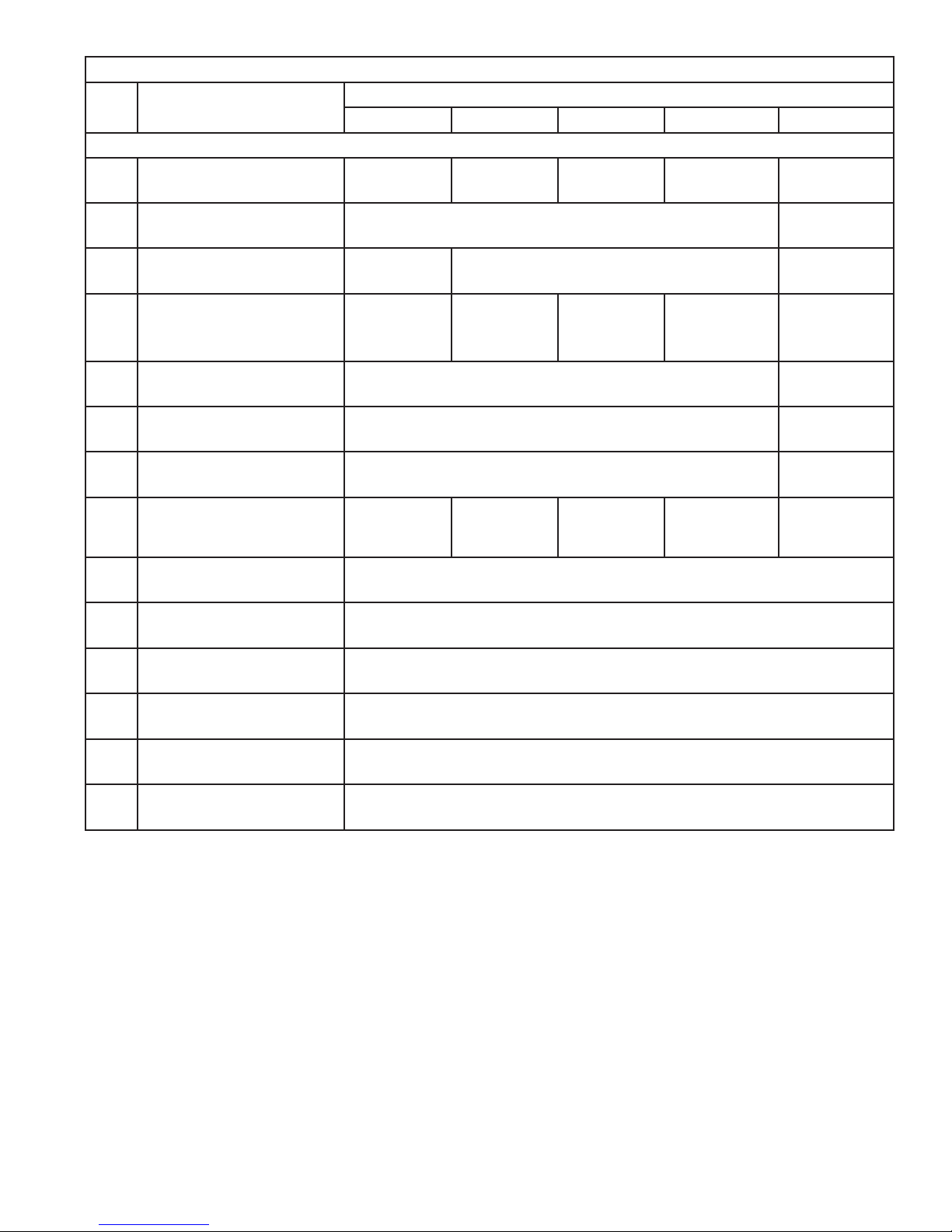
Key
Description (Quantity) Part Number
No.
4. JACKET ASSEMBLY
4A Jacket Lower Front Panel
4B Jacket Upper Rear Panel
Jacket Center Rear
4C
Panel
JACKET
EVCA-750 EVCA-1000 EVCA-1500 EVCA-2000 EVCA-3000
(1)
60456342
---
(1)
60456343
70456279
(1)
60456344
(1)
704562471
(1)
(1)
60456345
(1)
104002-01
(1)
704563002
(1)
104001-01
4D Jacket Panel Left Side
4E Jacket Top Panel
4F Jacket Vestibule Panel
4G Jacket Upper Front Panel
4H Jacket Panel Right Side
4I Handle
4K Observation Port Lens
4L Observation Port Gasket
Observation Port Lens
4M
Retainer
4N Latch
Power Switch w/Filter
4P
Light
(1)
604563291
(1)
604563231
(1)
604563301
704562541
604563021
70456280
(1)
604563241
(1)
604563311
(1)
(1)
(1)
(1)
604563251
8056256
8026082
8206039
7186019
80861722
8136363
(2)
(1)
(2)
(1)
(2)
(1)
(1)
604563321
(1)
604563261
(1)
6045603010
(1)
704563000
(1)
604563000
(1)
104023-01
(1)
6045603020
73
Page 74
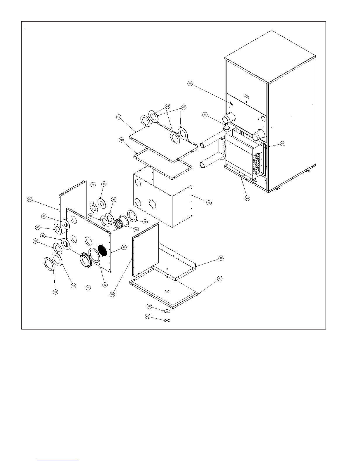
Figure 24: EVCA-750, 1000 and 1500 Secondary Heat Exchanger and Housing
74
Page 75
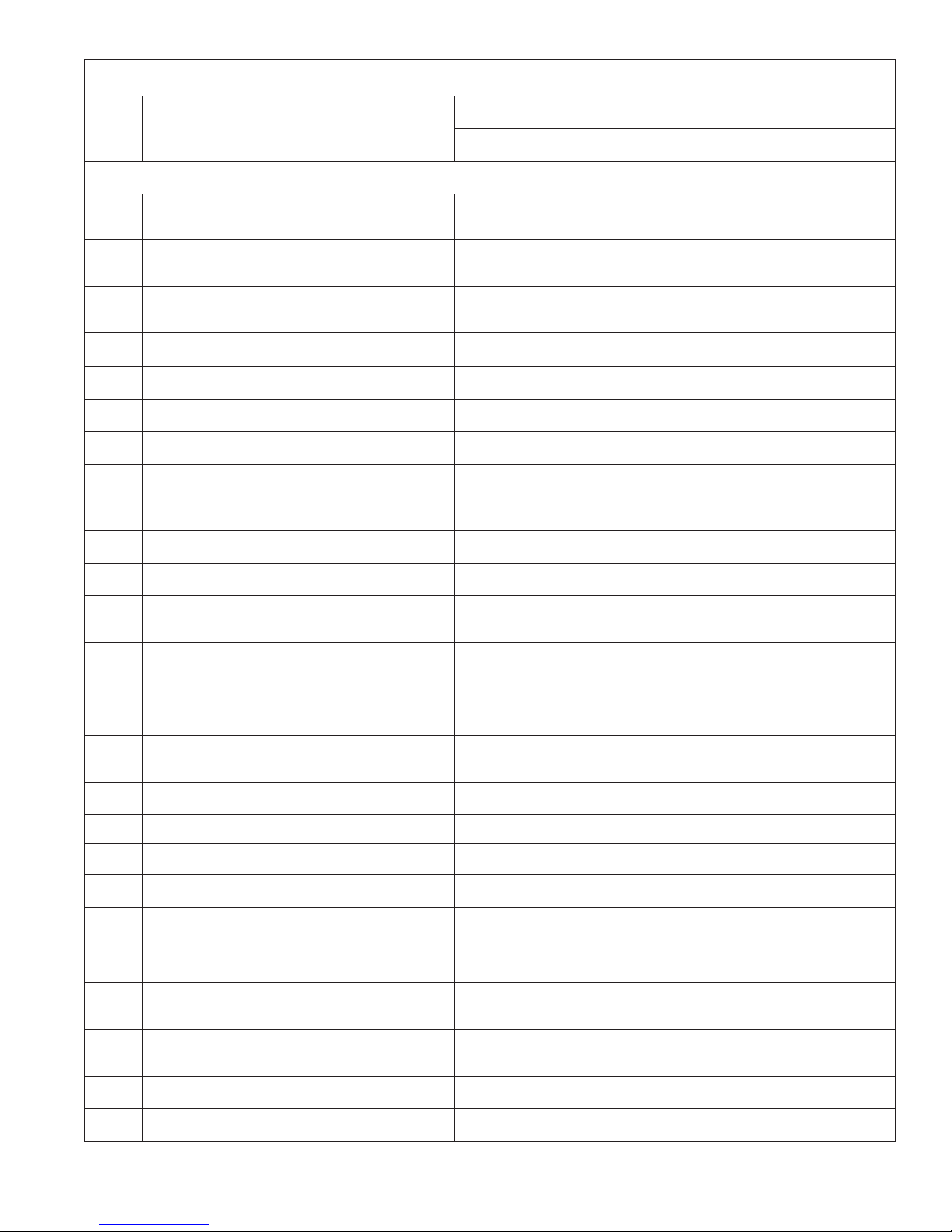
EVCA-750/1500 SECONDARY HEAT EXCHANGER AND HOUSING
Key
No.
Description
4. Secondary Heat Exchanger Housing
4A Secondary Heat Exchanger
4B Secondary Heat Exchanger Drain Pan
4C Secondary Heat Exchanger Wrapper
(Quantity) Part Numbe
EVCA-750 EVCA-1000 EVCA-1500
(1)
803EVC10750
(1)
803EVC11000
(1)
703EVC211
(1)
703EVC2003
(1)
703EVC2004
r
803EVC11500
703EVC2005
4D Secondary Heat Exchanger Top Pan (1) 703EVC20021
4E Stack Adapter (1) 811EVC004 (1) 811EVC006
4F 2” Trim Ring (2) 70456271
4G 2” Trim Ring Gasket (2) 8205643
4H 2-1/2” Trim Ring (2) 704EVC001
4I 2-1/2" Trim Ring Gasket (2) 8205676
4J Stack Adapter Gasket (1) 8205641 (1) 8205642
(1)
(1)
4K Stack Adapter Trim Ring (1) 70456121 (1) 70446129
Secondary Heat Exchanger Jacket
4L
Bottom Panel
4M
Secondary Heat Exchanger Jacket
Side Panel
Secondary Heat Exchanger Jacket
4N
Back Panel
Secondary Heat Exchanger Jacket Top
4O
Panel
4P Stack Trim Ring Gasket
604EVC220401
(2)
604EVC22010
604EVC22011
(1)
604EVC22020
604EVC22021
(1) 604EVC2203
(
1) 820EVC01 (1) 820EVC02
(1)
(2)
604EVC22012
(1)
604EVC22022
01
4Q 1/2" Condensate Trim Ring (1) 704EVC002
4R 1/2" Condensate Trim Ring Gasket (1) 8205677
4S 3" Trim Ring (2) 704EVC004 (2) 70456272
4T 3" Trim Ring Gasket (2) 8205644
4U Jacket Center Rear Panel
Secondary Heat Exchanger Left
4V
Mounting Bracket
Secondary Heat Exchanger Right
4X
Mounting Bracket
(1)
604EVC21010
(1)
703EVC26
(1)
703EVC22
(1)
604EVC21011
(1)
703EVC27
(1)
703EVC23
604EVC21012
703EVC28
703EVC24
(2)
(1)
(1)
(1)
(1)
4Y Air Inlet Trim Ring (1) 81156106 (1) 81156108
4Z Air Inlet Trim Ring Gasket (1) 82056106 (1) 82056108
75
Page 76
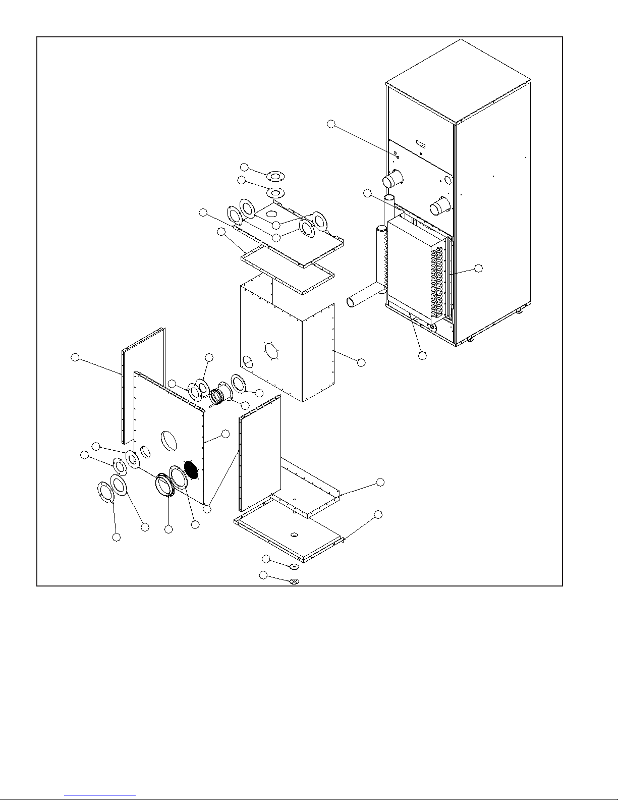
4U
4F
4G
4W
4O
4D
4T
4S
4X
4M
4H
4G
4H
4J
4K
4Y
4G
4P
4E
4N
4M
4Z
4R
4Q
4C
4B
4L
4A
Figure 25a: EVCA-2000 Secondary Heat Exchanger and Housing
76
Page 77

EVCA-2000 SECONDARY HEAT EXCHANGER AND HOUSING
Key Number Description
(Quantity)
Part Numbe
EVCA-2000
r
4. EVCA-2000 Secondary Heat Exchanger Housing
-
-
Boiler Drain Trim Ring, 1" (not shown) (1) 70456136
Boiler Drain Trim Ring Gasket, 1" (not shown) (1) 8205651
4A Secondary Heat Exchanger (1) 803EVC12000
4B Secondary Heat Exchanger Drain Pan (1) 703EVC21
4C Secondary Heat Exchanger Wrapper (1) 703EVC2006
4D Secondary Heat Exchanger Top Panel (1) 703EVC2002
4E Stack Adapte
r
(1) 811EVC006
4F Modied 2-1/2” Trim Ring (1) 704EVC003
4G 2-1/2” Trim Ring Gasket (4) 8205676
4H 2-1/2” Trim Ring (3) 704EVC001
4J Stack Adapter Gasket (1) 8205642
4K Stack Adapter Trim Ring (1) 70456129
4L Secondary Heat Exchanger Jacket Bottom Panel (1) 604EVC22040
4M Secondary Heat Exchanger Jacket Side Panel (2) 604EVC22013
4N Secondary Heat Exchanger Jacket Rear Panel (1) 604EVC22023
4O Secondary Heat Exchanger Jacket Top Panel (1) 604EVC22030
4P Stack Adapter Gasket (1) 820EVC02
4Q Condensate Drain Trim Ring, 1/2" (1) 704EVC002
4R Condensate Drain Trim Ring Gasket, 1/2" (1) 8205677
4S Water Trim Ring, 3" (2) 70456272
4T Water Trim Ring Gasket, 3" (2) 8205644
4U Jacket Center Rear Panel (1) 604EVC21013
4W Secondary Heat Exchanger Left Mounting Bracket (1) 703EVC29
4X Secondary Heat Exchanger Right Mounting Bracket (1) 703EVC25
4Y Air Inlet Ring, 8" (1) 81156108
4Z Air Inlet Ring Gasket, 8" (1) 82056108
77
Page 78
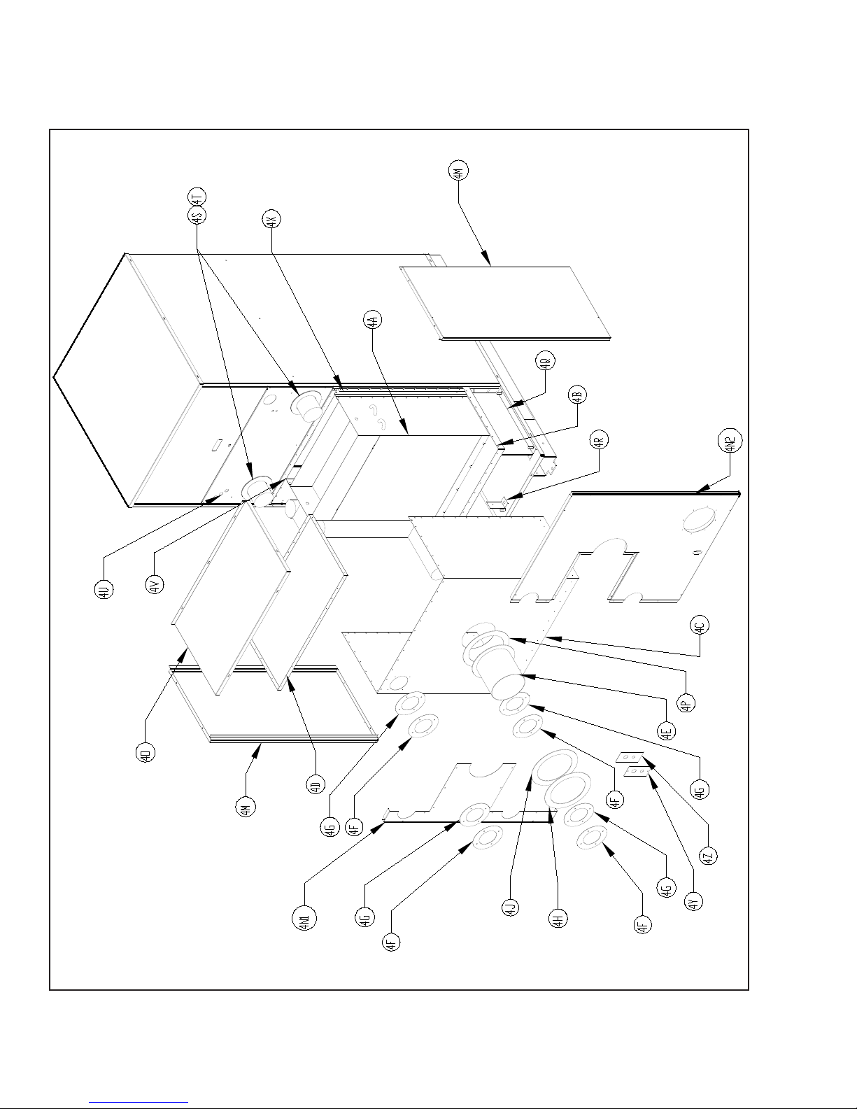
Figure 25b: EVCA-3000 Secondary Heat Exchanger and Housing
78
Page 79

EVCA-3000 SECONDARY HEAT EXCHANGER AND HOUSING
Key
No.
Description
(Quantity) Part Numbe
EVCA-3000
4. Secondary Heat Exchanger Housing
4A Secondary Heat Exchanger (1) 104019-01
4B Secondary Heat Exchanger Drain Pan (1) 103083-02
4C Secondary Heat Exchanger Wrapper (1) 104018-01
4D Secondary Heat Exchanger Top Pan (1) 104017-01
4E Stack Adapter (1) 811EVC008
4F 3-1/2” Trim Ring (4) 70456150
4G 3-1/2” Trim Ring Gasket (4) 8205678
4H Stack Adapter Trim Ring (1) 70456128
4J Stack Adapter Trim Ring Gasket (1) 8205660
4K Air Inlet Trim Ring (1) 81156108
4L Air Inlet Trim Ring Gasket (1) 82056108
4M Secondary Heat Exchanger Jacket Side Panel (2) 104004-01
4N1 Secondary Heat Exchanger Jacket Rear Panel, Water Side (1) 103099-01
4N2 Secondary Heat Exchanger Jacket Rear Panel, Intake Side (1) 103098-01
4O Secondary Heat Exchanger Jacket Top Panel (1) 104005-01
4P Stack Trim Ring Gasket (1) 820EVC03
4Q Secondary Heat Exchanger Pan Support Brace (2) 103079-01
4R Condensate Line Brace (1) 104022-01
4S 4" Trim Ring (2) 70456131
4T 4" Trim Ring Gasket (2) 8205661
4U Jacket Panel, Lower Rear (1) 104001-01
4V Secondary Heat Exchanger Support Brace, Horn Side (1) 104015-01
4X Secondary Heat Exchanger Support Brace, Closed Side (1) 104016-01
4Y Condensate Line Trim Ring (1) 104020-02
4Z Condensate Line Trim Ring Gasket (1) 104021-02
4AA 5/8" Condensate Line Extension (not shown) (1) 104025-01
4AB 1/2" Condensate Line Hose (not shown) (1) 103302-02
4AC 5/8" Condensate Line Extension Fitting (not shown) (1) 104026-01
r
79
Page 80
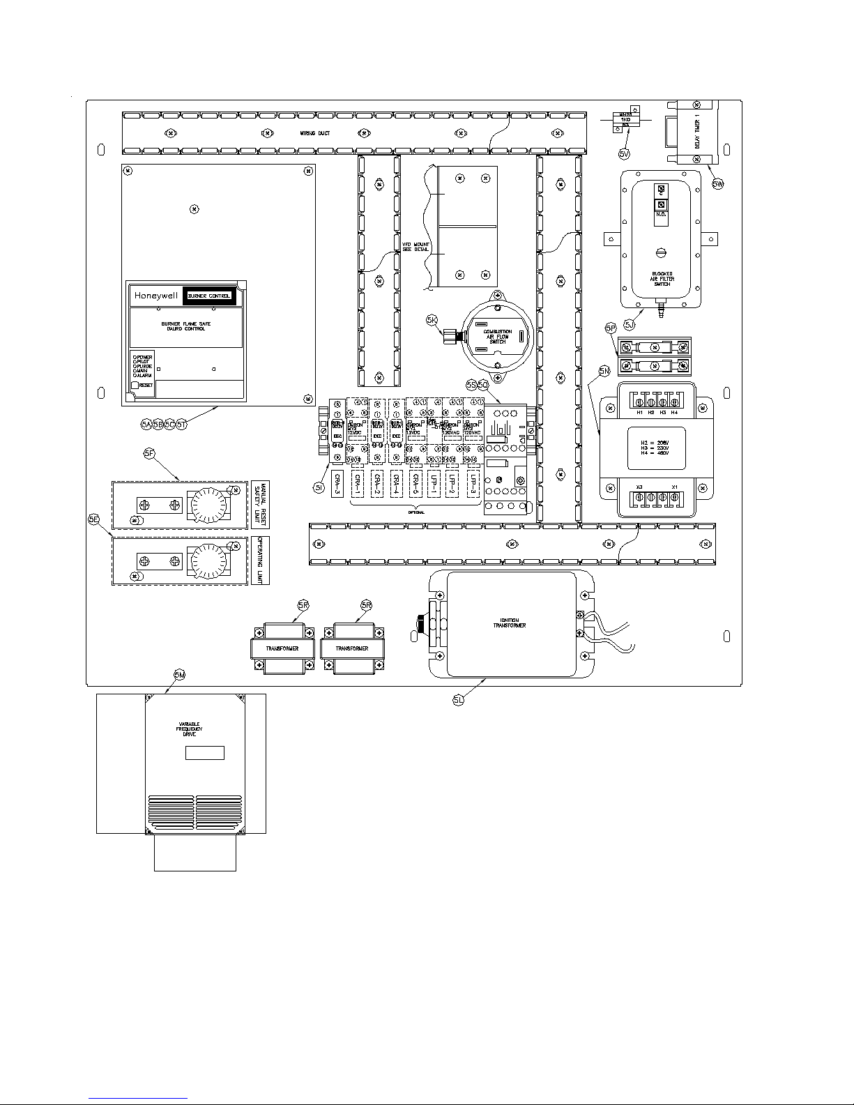
Figure 26: Control Panel Assembly
80
Page 81
Controls
Key
No.
Description (Quantity) Part Numbe
5. Controls and Components
RM7896D1027 Flame Safeguard Control for UL/FM/CSD-1/DB&B (1) 80160212
RM7840L1075 Flame Safeguard Control for DB&B w/POC/LFP (1) 801602303
5A
Modbus Module for 5A (optional - not shown) (1) 80160909
Display Module for 5A (optional - not shown) (1) 80160640
5B Amplier Card (not shown) R7849A1023 (1) 80160243
Purge Card (not shown) ST7800A1039, UL/FM/CSD-1/DB&B/LFP (1) 8136362
5C
Purge Card (not shown) ST7800A1005, DB&B w/POC (1) 81363621
5D Power Switch w/Filter Light (not shown) (1) 8136363
5E Operating Limit L4008A1015 (Auto Reset) (1) 80160626
5F High Limit L4008E 1313 (Manual Reset - Max 240F) (1) 80160667
5G Water Flow Switch FS4-3 (not shown) (1) 80160175
5H Vestibule Fuse Switch (not shown) (1) 80160209
5I Contact Relay 12V DC (1) 80160768
5J Blocked Filter Switch (1) 80160295
5K Combustion Air Flow Switch (1) 102382-02
5L Ignition Transformer (1) 80160018
Variable Frequency Drive 208/230 volt input (1) 80160940
5M
Variable Frequency Drive 460 volt input (1) 80160941
Variable Frequency Drive 115/120 volt input (1) 80160933
5N Control Transformer (1) 80160820
5P Fuses and Fuse Block, for 208/230/460V Application (2) 8136426, (2) 8136427
5Q Overload Relay See Table Below
5R Transformer AT140B1206 (2) 801600502
5S Contactor 3PH 120 Volt Coil (see table below for permutations) See Table Below
5T Q7800H1109 Board for Thermal Solutions Boiler Control (TSBCTM) (1) 101182-01
5U Thermal Solutions Boiler Control (TSBC) Assembly (not shown) (1) 101171-03
5V Resistor, 1K ohm, 25 watt (LFP boiler only) (1) 103577-01
5W Delay Timer (LFP boiler only) (1) 80160675
r
Description 5Q 5S
120V - 1 Phase, EVCA-750/1000 813EVC60004 813EVC60001
208/230V - 1 Phase, EVCA-750/1000 813EVC60003 813EVC60001
208/230 - 3 Phase, EVCA-750/1000 813EVC60002 813EVC60001
120V - 1 Phase, EVCA-1500/2000 813EVC60009 813EVC60007
208/230V - 1 Phase, EVCA-1500/2000 813EVC60004 813EVC60001
208/230V - 3 Phase, EVCA-1500/2000 813EVC60003 813EVC60001
460V - 3 Phase, EVCA-750/1000 813EVC60008 813EVC60001
460V - 3 Phase, EVCA-1500/2000 813EVC60002 813EVC60001
208/230V - 3 Phase, EVCA-3000 813EVC60005 813EVC60001
460V - 3 Phase, EVCA-3000 813EVC60003 813EVC60001
81
Page 82
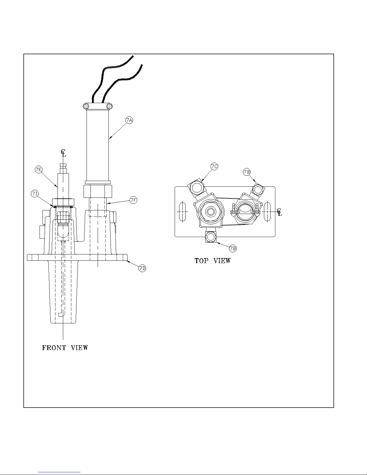
Figure 27: "Bishop" Pilot Assembly
82
Page 83
PILOT ASSEMBLY
Key
No.
Description
6. Pilot Assembly
Pilot Assembly Natural Gas,
ULX2
--Pilot Assembly Propane,
ULX2
7A Ultraviolet Sensor
Pilot Orice Natural Gas
7B
Pilot Orice Propane
7C Pilot Air Orice
7D Cast-Iron Body
7E Ignitor Assembly, ULX2
7F Nipple, 1/2” NPT X Close
Pilot Ignition Cable (not
7G
shown)
Pilot Solenoid Valve
7H
V4048C1047 (not shown)
7I O-Ring
(Quantity) Part Number
EVCA-750 EVCA-1000 EVCA-1500 EVCA-2000 EVCA-3000
(1)
62356110
(1)
62356210
(1)
8026145
(1)
722606
(1)
722605
(1)
722607
(1)
82361581
(1)
82356009
(1)
806600040
(1)
103827-01
(1)
81660204
(1)
8206054
83
Page 84
EVCA LOOP PIPING - MAJOR COMPONENTS
Key
No.
Description
8. EVCA Loop Piping
1-Phase 120/208/230V
¼ HP Pump
3-Phase 208/230/460V
¼ HP Pump
1-Phase 120/208/230V
8A
¾ HP Pump
3-Phase 208/230/460V
¾ HP Pump
3-Phase 208/230/460V
2 HP Pump
8B Temperature Probe
8C 3-Way Valve
8D 3-Way Valve Actuator
3-Way Valve and Actuator
8E
Assembly
(Quantity) Part Number
EVCA-750 EVCA-1000 EVCA-1500 EVCA-2000 EVCA-3000
(1)
805622005
(1)
805622006
—
—
— —
— —
— —
(1)
805622007
(1)
805622008
—
—
(1)
104033-02
(1)
101935-01
(1)
102653-01
(1)
101894-01
—
—
—
(1)
104032-01
84
Page 85

IX. Thermal Solutions Boiler Control™ (TSBC™)
A. INTRODUCTION - e intent of this section is to briey summarize the controllers capabilities, familiarize the user with its
basic features and to list the factory supplied default settings. Read the additionally supplied Factory Instruction Manual for
the TSBC to learn more about the controllers features and capabilities.
1. Thermal Solutions Boiler Control™ Overview
e ermal Solutions Boiler Control™ (TSBC™) is a complete boiler monitoring and automation system. e TSBC™
provides advanced boiler modulation, operating control, diagnostics, multiple boiler lead-lag and auxiliary device control.
e TSBC™ provides advanced control features in an easy to use package.
2. Flexible, Field Selectable Control
Control modes, water system, boiler auxiliary
and modulating lead/lag control features are
menu selectable without the need for external
programmers, lap tops or down loads. Every boiler
is shipped with factory defaults that make eld
menu selections unnecessary unless you are applying
additional control features.
3. Boiler Monitoring and Diagnostic Displays
e TSBC™'s two line by sixteen character LCD
display may be used for monitoring boiler inlet and
outlet, remote system and outside air temperatures,
modulation rate setpoint and modulating percent
and mixing valve demand percent. Additionally,
the display automatically presents boiler sequence
messages, alarms, hold and lockout messages. A
diagnostic menu is included that provides the last
10 alarm messages and boiler inlet temperature
alarm history. Boiler inlet temperature alarm history
includes time and date, the lowest inlet temperature
reached and the amount of time the water
temperature dropped below the alarm setpoint.
4. Modulation Rate and On/Off Modes
e TSBC™ may simply control boiler modulation
and on/o output based on the boiler water outlet
temperature and an operator adjusted setpoint.
However, using parameter selections, the TSBC™
allows the boiler modulation and on/o output
to respond to remote system water and outside
air temperatures, Domestic Hot Water Priority
(DHWP) input or Energy Domestic Hot Water
Priority (EMS) modulation rate demand, remote
setpoint or remote start/stop commands. Parameter
selections of remote system water temperature and
remote mode determine the choice of one of six
dierent control modes.
5. Advanced Availability
e above control modes are menu selectable
options. However, if a selected sensor fails, the
TSBC™ automatically changes to a control mode
that will allow continued automatic operation of
the boiler. For example, in the event of a remote
system temperature sensor failure, the TSBC™ will
automatically switch to boiler outlet temperature
sensor based control.
6. Outdoor Air Reset
When selected the modulation rate setpoint
is automatically adjusted based on outside air
temperature. Outdoor air "reset" setpoint saves
fuel by adjusting the water temperature of a heating
boiler lower as the outside air temperature increases.
7. Warm Weather Shutdown (WWSD)
Some boilers are used primarily for heating
buildings, and the boilers can be automatically
shutdown when the outdoor air temperature is
warm. When outside air temperature is above the
WWSD setpoint, this function will prevent the
boiler, boiler pump and/or the system pump from
starting.
8. Domestic Hot Water Priority (DHWP)
Some boilers are used primarily for building space
heating, but also provide heat for the domestic hot
water users. When the outdoor temperature is
warm, the outdoor reset setpoint may drop lower
than a desirable domestic hot water temperature.
When enabled and a DHWP contact input is
detected, the hot water setpoint is adjusted to be
greater than a eld adjustable DHWP Setpoint.
9. Water Side Control Outputs
In order to maximize the life and availability of a
hot water systems it may be desirable to automate
mixing valves, boiler pumps, system pumps, and
standby system pumps. e TSBC™ makes this
type of automation totally integrated and cost
eective. e control of these devices is eld
selectable through simple yes/no menu selections.
10. Combustion Air Side Control Outputs
Boiler room Combustion air dampers (fresh air
dampers) and Vent Inducer control outputs are eld
selectable options.
11. Peer-To-Peer Network
e TSBC™ includes state-of-the-art modulating
lead-lag sequencer for up to eight (8) boilers capable
of auto rotation, outdoor reset and peer-to-peer
communication. e peer-to-peer network is truly
"plug and play". Communication is activated by
simply connecting a RJ11 telephone line between
boilers. e TSBC™ provides precise boiler
coordination by sequencing boilers based on
85
Page 86
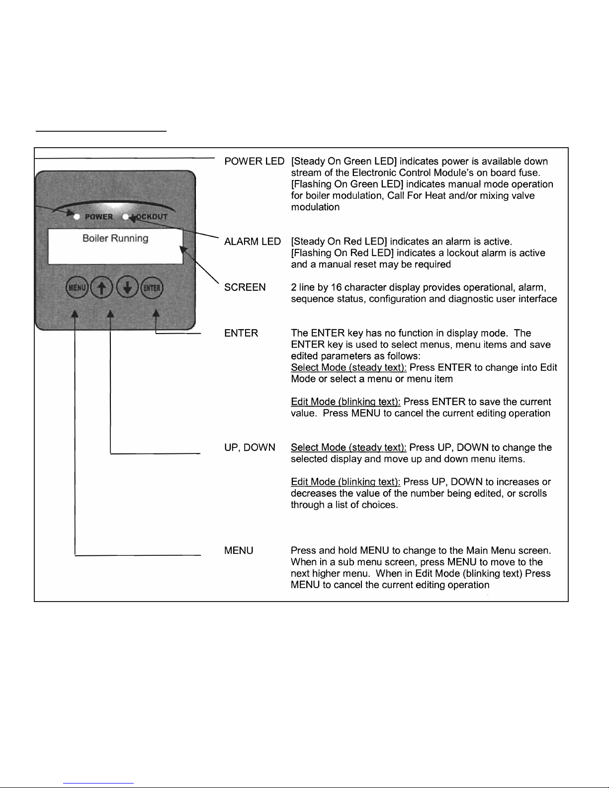
both remote system water temperature and boiler
modulation rate. For example, the lead boiler can be
congured to start a lag boiler aer operating above
90% modulation rate for longer than an adjustable
time. e boilers are modulated in "unison"
(parallel) modulation rate to ensure even heat
B. FRONT PANEL DISPLAY
distribution.
12. Modbus Communication Interface
A factory congured RS485 Modbus interface is
available for Energy Management System (EMS) or
SCADA system monitoring and control.
B. Thermal Solutions Boiler ControlTM (TSBCTM) Wiring
When wiring to the ermal Solutions Boiler Control (TSBC™) terminals, see the terminal layout drawing on the following
page or the terminal jacket label, located on the inside surface of the boiler jacket upper front panel. e TSBC™ terminals are
removable for easier eld wiring connection.
86
Page 87
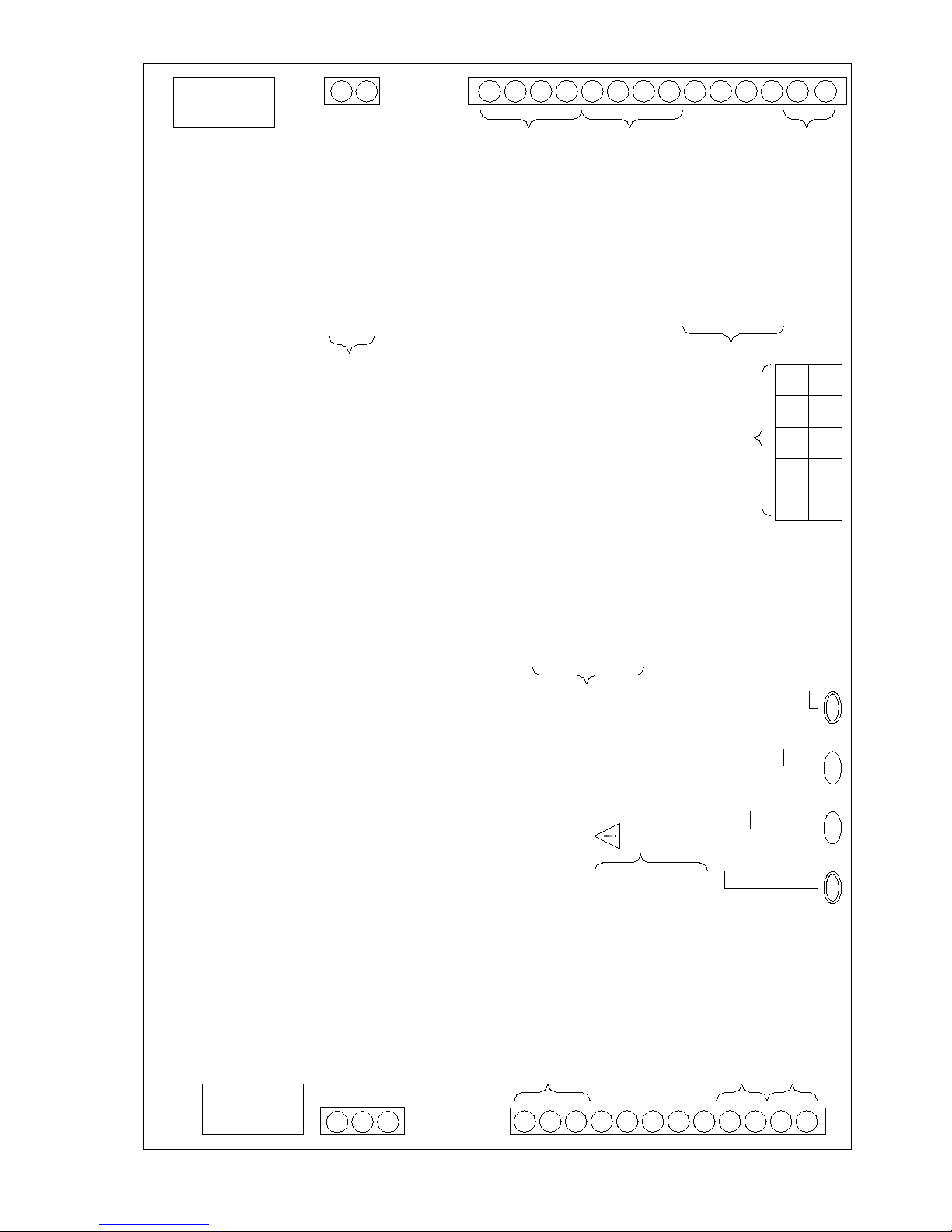
C
R-
O-
LC
CH
RJ-45
(8 pin)
O+
O+
O-
R+
R+
R-
DP
LR
RO
SI
C
Alternate Connection For
Outside Air Temperature and
(TSBC™)
Remote System Temperature
(10k ohm Thermister, 5 Vdc)
Low Water Cutoff Switch Input
24
WARNING:
Vac
Call For Heat Output
NOTE:
Outside Air Temperature
(10k ohm Thermister, 5 Vdc)
CA - Low Combustion Air Flow
Local / Remote
12 Vdc Common
Remote On / Off (Enable)
Remote System Temperature
(10k ohm Thermister, 5 Vdc)
Domestic Hot Water Priority
12
P-, P+ - Firing Rate Demand (0-10 Vdc, PWM)
V-, V+ - Firing Rate Demand (0-10 Vdc)
HL - Operating or High Limit
GP - Gas Pressure Switch
WF - Low Water Flow Switch
OO - Burner On/Off Switch
Vdc
Spare Input (Programmable)
CA
GPWF HL
Fuel Valve Energized
OO
V-V+P-P+
(24 Vac)
24
Vac
12 Vdc,
(24 Vac)
Flame Safeguard Alarm
Power Supply (+24 Vac)
SP and SO
for LO, VI, BP,
0.5 A max total
Thermal Solutions Boiler Control™
TERMINAL LAYOUT GUIDE
(Terminal connections as viewed from front of boiler)
See boiler wiring diagram for details.
All connections have different inputs and outputs.
Valid signal range for terminals C+ and C- is 1-9VDC.
Refer to connections on diagrams for individual inputs/outputs.
Power Common (-24 Vac)
C PR AL CS
Communication
Boiler Peer-To-Peer
Network
(10k ohm Thermister, 5 Vdc) Common
Boiler Outlet Temperature
Boiler Inlet Temperature
RJ-11
Label 101175-04
(6 pin)
BC
BO
BI
12Vdc Common
C
C
C
Spare Output (Programmable)
SO
System Pump Start/Stop
SP
Boiler Pump Start/Stop
BP
Spare Output Start/Stop
VI
Lockout Indicator
LO
Mixing Valve Output
MR
(4-20 mAdc)
MS
Remote Firing Rate or
C-
Setpoint Input (0-10 Vdc)
(See Note)
C+
87
Page 88
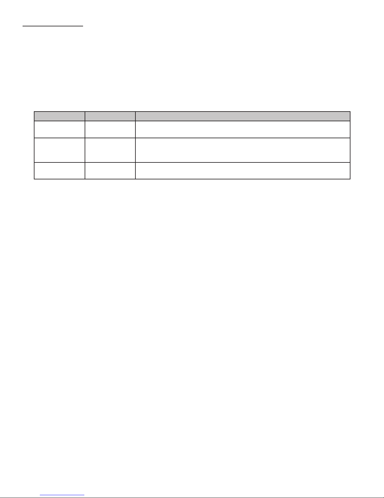
C. SECURITY MENU
1. Press and hold the MENU button to enter menu mode.
2. Access parameters and set password.
a. In MENU mode page through to the SECURITY menu and press ENTER.
b. Page down to the "Enter Password" parameter and press ENTER.
c. Use the arrow buttons to change the password value to the desired password and hold ENTER until the screen ashes.
3. e access level will reset to Basic aer one hour if no key is pressed, or if power is removed.
PASSWORD
Access Level Enter Password Description
Basic 0 (NONE)
Supervisor 15
Factory
Consult Thermal Solutions Boiler Control (TSBC) Instruction manual for operation guidance and a detailed list of parameters
and their associated access levels.
This is the default access level. The user can view many parameters, but is only
allowed to edit a small sub-set of the parameters that are visible.
This password is set at the factory but can be changed in the eld. The user can
view and edit most parameters that are visible. Note: Not all parameters will be visible at the Supervisor Access Level.
All relevant internal parameters in the system will be visible and programmable.
Please consult Thermal Solutions for the factory access level password.
88
Page 89
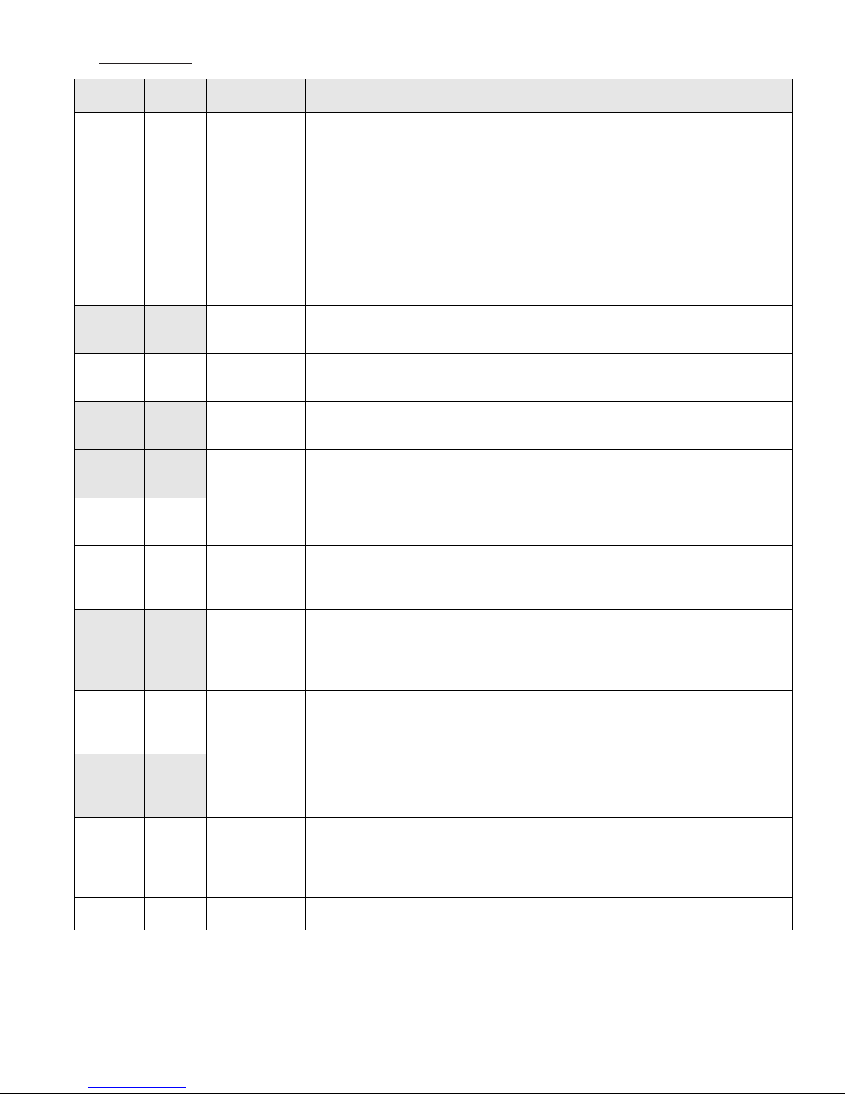
D. SETUP MENU
EVCA Modulating Fire Test Procedures and Specifications
APPENDIX D (Cont…) - TSBCTM SETUP Menu
Factory
Trigger
Boiler
Delay
The Net Start Dwell Time Delay specifies the length of time the peer-to-peer network
The Limit Fault time Delay specifies the length of time the peer-to-peer network will
Specifies number of hours (cumulative) a lead boiler runs before passing the lead to
satisfying a DHWP request
Rotation
Specifies number of hours (cumulative) a lead boiler runs before passing the lead to
Display
Settings
WWSD Off
LL Start
Trigger
LL Stop
Boiler
On Delay
Off
%FR On
Delay
%FR Off
Delay
High Fire
Limit
Deg/Min
Hold Off
Cutback
Setpoint
90 50 to 100 %
25 0 to 50 %
120 0 to 900 (s)
30 0 to 900 (s)
1 1 to 30 (m)
1 1 to 30 (m)
100 40 – 100 %
1 1-10 F
Boiler
220
Range/Choices Description
Specifies Warm Weather Shut-Down (WWSD) control of boiler and/or system pump.
Off
WWSD of Boiler
WWSD of Sys
Pump
Both
100 to 240 F
Off: Ignores Warm Weather setpoint
WWSD of boiler: When Outside Air Temperature (OAT) is higher than the
WWSD of Sys Pump: When OAT is higher than the WWSD setpoint de-energize
Both: When OAT is higher than the WWSD setpoint, inhibit Call
Specifies the percent of maximum modulation rate the running boiler(s) must reach
before calling upon additional boilers for help.
Specifies the percent of modulation rate that the running boiler(s) must be below
before shutting down a lag boiler
Time Delay after On Point setpoint has been reached before starting the next boiler.
Short time delay to prevent nuisance starts due to momentary temperature and
modulation rate swings.
Time Delay after the Off Point setpoint before stopping the next boiler. Short time
delay to prevent nuisance stops due to momentary temperature and modulation rate
swings.
Time Delay after the modulation rate is above the LL Start Trigger before starting the
next boiler. Shorten time delay to avoid temperature going below setpoint as a result of
a slow process change.
Time Delay after the modulation rate is below the LL Stop Trigger before stopping
the next boiler. Shorten time delay to avoid temperature going above setpoint as a
result of a slow process change.
High modulation rate limit for all boilers on the peer-to-peer network as long as at
least one boiler is still not running. After the last boiler has started the modulation
rate is released up to 100.
Specifies a temperature rate of change that inhibits the next boiler being started or
stopped. If the temperature is increasing faster than this rate of change, the next
boiler is not started. Also, if the temperature is decreasing faster than this rate of
change, the next boiler is stopped.
Boiler outlet temperature above the Cutback Setpoint causes the modulation rate to
be reduced proportionally to help avoid a high temperature limit lockout. This
parameter is significant while the modulation rate of the boiler is controlled
according to the remote system temperature sensor, remote input (C+, C-) or Modbus
(40006).
WWSD setpoint, inhibits boiler start
System Pump output (SO)
for Heat and de-energized system pump output (SO)
Net Start
Dwell
Limit
Fault
Time
Rotation Disable
After
120 16 to 420 (s)
5 3 to 120 (s)
Disable
Enable
168 8-720 (hr)
will wait for the Main Fuel Valve Energized input (CS) to be energized after a boiler
call for heat. If the Net Start Dwell time is exceeded before the main fuel valve is
open, the next boiler Call for Heat is immediately initiated.
wait for the boiler limits input (CA) to be energized after a boiler Call for Heat. If the
Limit Fault time is exceeded before the limits are energized, the next boiler Call for
Heat is immediately initiated.
another boiler.
Lead role will be surrendered earlier if the lead boiler is placed into manual mode, is
run remotely (mode 6), fails to start, is “blind” (all input sensors failed), or is
another boiler.
89
Page 90
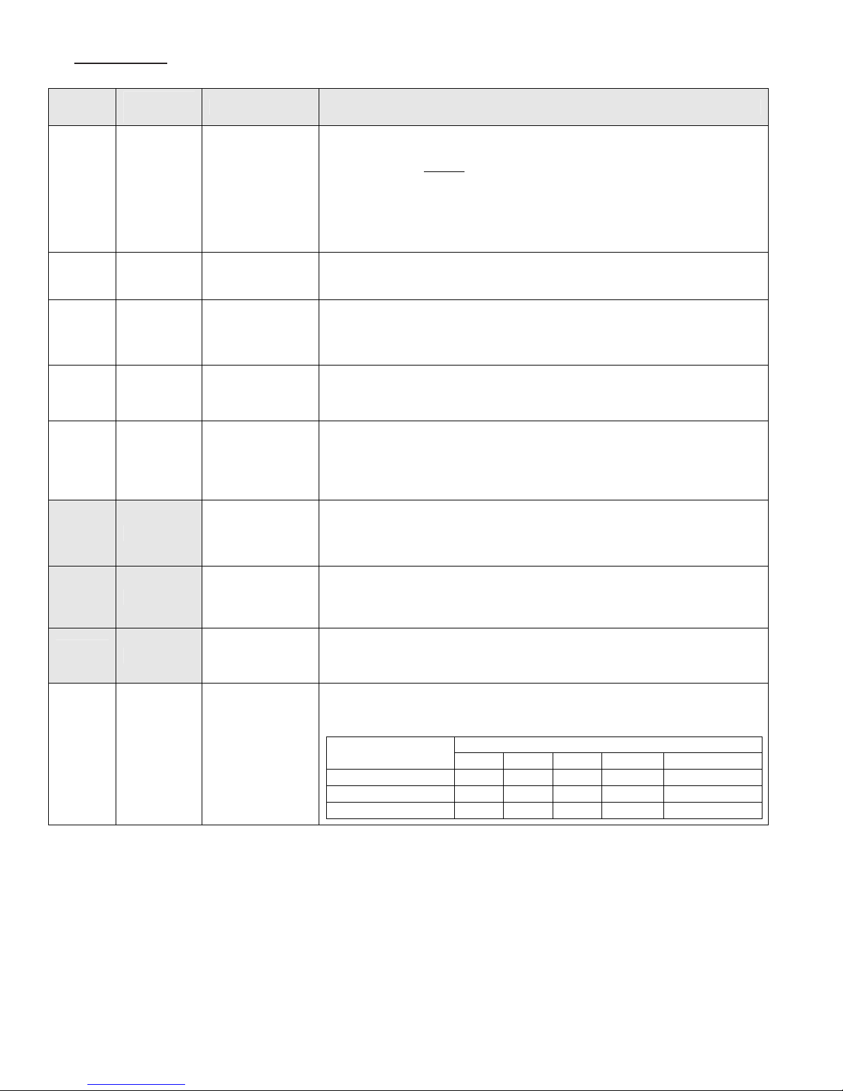
D. SETUP MENU (continued)
EVCA Modulating Fire Test Procedures and Specifications
APPENDIX D (Cont…) - TSBCTM SETUP Menu
Display
Outdoor
Sensor
Outdoor
Set Up
Boiler
Set Up
Outdoor
Design
Boiler
Design
Factory
Settings
No
55 40 F to 100 F
140 80F to 180 F
30 -20 F to 50 F
180 80F to 220 F
Range/Choices Description
Enables the Outside Air Temperature sensor display and control logic.
No: Outside Air Input (O+O-) is ignored.
No
Display Only
Outdoor Reset
Display Only: Do Not
Outdoor Reset: Calculate the temperature setpoint based on outdoor
The Outdoor Set Up temperature is the outdoor temperature at which the
Boiler Set Up temperature is supplied.
Only visible when Outdoor Sensor is set to Outdoor Reset .
The Boiler Set Up Temperature is the starting boiler water temperature of the
reset ratio. If the building feels cool during mild outdoor conditions, the
Boiler Set Up setting should be increased.
Only visible when Outdoor Sensor is set to Outdoor Reset.
The Outdoor Design Temperature is the outdoor temperature at which the
Boiler Design temperature is supplied.
Only visible when Outdoor Sensor is set to Outdoor Reset.
The Boiler Design setting is the water temperature required to satisfy the
building heat loss during the Outdoor Design temperature. If the building feels
cool during cold outside conditions, the Boiler Design setting should be
increased.
Only visible when Outdoor Sensor is set to Outdoor Reset.
Calculate setpoint based on outdoor temperature,
Display Outside Air Temperature.
temperature using a reset curve defined by Outdoor Set Up,
Boiler Set Up, Outdoor Design and boiler Design
parameters.
Blower
SPD
High
Blower
SPD
Low
Low Fire
Spd
Fan
Purge
Spd
Percent of (0 - 10 vdc output (V+, V-) output that represents a 100%
100 0 to 100 %
0 0 to 100 %
50 0 to 100 % Modulation % used for Low Fire Hold and Low Fire Start conditions.
See
Description
0 to 100 %
modulation rate. This scaling factor allows the controller to display 100%
when the blower is at rated boiler output.
Percent of (0 - 10 vdc output (V+, V-) output that represents a 0% modulation
rate. This scaling factor allows the controller to display 0% when the blower is
at minimum boiler output.
Percent of blower operating range that the blower should be run during Fan
Purge (at ignition).
Build
Standard 100 100 100 100 55
Low fire proving 25 24 23 26 55
Venturi 100 100 23 26 N/A
750 1000 1500 2000 3000
Boiler model
90
Page 91
EVCA Modulating Fire Test Procedures and Specifications
APPENDIX D (Cont…) - TSBCTM SETUP Menu
D. SETUP MENU (continued)
Display
Low
Fire
Hold
Post
Purge
Time
Local
Pid
P
Local
PID
I
Local
PID
D
Remote
PID
P
Remote
PID
I
Remote
PID
D
Mixing
Valve
P
Mixing
Valve
I
Mixing
Valve D
Max
Delta T
P
Max
Delta T
I
Max
Delta T
D
Factory
Settings
20 10 to 1200 (s)
30 0 to 600 (s)
20 0 to 10000
30 0 to 10000
0 0 to 10000
20 0 to 10000
30 0 to 10000
0 0 to 10000
10 0 to 10000
60 0 to 10000
0 0 to 10000
10 0 to 10000
60 0 to 10000
0 0 to 10000
Range Description
Time modulation rate is held at present value (Low Fire Spd or Fan Purge Spd
depending on the state and configuration of spare input) after the Fuel Valve
Energized Input (CS) is energized.
Time modulation rate is held at Fan Purge Spd after the Fuel Valve Energize Input
(CS) is de-energized.
Proportional Gain value for boiler outlet temperature sensor control Modes. A larger
gain value results in tighter, more active, PID control. Gain is the primary PID
modulation rate tuning adjustment and provides the immediate modulation rate
response.
Integral gain value for boiler outlet temperature sensor control Modes. A smaller
value makes the Integral ramp in less time (i.e., faster). Integral is a secondary PID
modulation rate tuning adjustment that ramps the output over time (typically
minutes).
The Derivative gain value for boiler outlet temperature sensor control Modes. A
larger Derivative gain value produces a larger PID output contribution proportional to
the rate of change of the error (Setpoint – Boiler Outlet Temperature). When set
equal to zero it has no effect on the output.
Proportional Gain value for Remote System Temperature sensor control Modes.
Refer to Local PID P for explanation.
Integral Gain Term for Remote System Temperature sensor control Modes. Refer to
Local PID I for explanation.
Derivative Gain Term for Remote System Temperature sensor control Modes. Refer
to Local PID D for explanation.
Proportional Gain value for boiler Inlet temperature sensor control mode. A larger
gain value results in tighter, more active, PID control. Gain is the primary PID
modulation rate tuning adjustment and provides the immediate mixing valve
modulation response.
Only visible when mixing valve = yes.
Integral gain value for boiler inlet temperature sensor control mode. A smaller value
makes the Integral ramp in less time (i.e., faster). Integral is a secondary PID
modulation rate tuning adjustment that ramps the output over time (typically
minutes).
Only visible when mixing valve = yes.
The Derivative gain value for boiler inlet temperature sensor control mode. A larger
Derivative gain value produces a larger PID output contribution proportional to the
rate of change of the error (Setpoint – Boiler Inlet Temperature). When set equal to
zero it has no effect on the output.
Only visible when mixing valve = yes.
Proportional Gain value for boiler differential (boiler outlet minus inlet temperature
sensor) temperature control mode. Refer to Local PID P for explanation.
Only visible when mixing valve = yes.
Integral Gain value for boiler differential (boiler outlet minus inlet temperature
sensor) temperature control mode. Refer to Local PID I for explanation.
Only visible when mixing valve = yes.
Derivative Gain Term for boiler differential (boiler outlet minus inlet temperature
sensor) temperature control mode. Refer to Local PID D for explanation.
Only visible when mixing valve = yes.
91
Page 92

E. BOILER CONFIGURATION MENU
EVCA Modulating Fire Test Procedures and Specifications
APPENDIX D (Cont…) - TSBCTM BOILER CONFIG Menu
N
Display
Display
Units
Factory
Setting
Deg F
Boiler
Pump
Purge
Pump
Prepurge
Postpurge
Delta
Inlet
Sensor
Mixing
Valve
Set
Time/Date
Spare
Input
15 0 to 600 (s)
5
Yes
Yes
-
Off
Range/
Choices
Deg F
Deg C
None
Always On
Purge
Lead On
0 to 20
(C or F)
No
Yes
No
Yes
hour : minute
Month / day /
year
Off
Sys Pump
FB
Low Fire
Description
Selects how temperature parameter values are displayed.
None: No Boiler Pump.
Always On: Pump Runs Continuously.
Purge: Pump Runs during pump pre/post purge operations and during call
for heat and then turns off.
Lead On: Lead boiler’s pump runs continuously when the boiler is the lead
boiler and reverts to “Purge” operation when it is a lag boiler.
Sets length of time the boiler pump will be run prior to closing the “Call for Heat”
relay (CH).
Only visible when Boiler Pump does not equal None.
Defines the temperature above BIT that BOT must be at or below before turning off
the boiler pump during pump post purge (Pump Cooldown State).
Only visible when Boiler Pump does not equal None.
Enables the inlet temperature display and control logic.
Enables the mixing valve control output and user display.
Sets the time and date of the boiler’s real time clock. This item also displays the
time and date.
Sets the function of the Spare Input Terminal (SI).
Off: Ignore.
Sys Pump Feedback: Input (SI) should be wired to a flow switch inserted in the flow
path of the primary system pump. Input (SI) indicates the
primary system pump is operating. If output (SP) is set to
System Backup Pump, system pump output (SP) is
energized and System pump Feedback is de-energized the
System Backup Pump output (SP) is energized.
Low Fire: When the Fuel Valve Energized input (CS) is not energized
and Input (SI) is energized the modulation rate is set to the
“Low Fire Spd” setpoint. When input (SI) is not energized
the modulation rate is set to “Fan Purge Spd” setpoint.
When the fuel valve energized input (CS) is energized input
(SI) is ignored.
Fuel limit
Spare
output
Yes
Off
o
Yes
Off
CAD
System
Pump BU
Soft Alarm
Specifies whether high and low gas pressure switches are connected to input (GP).
Enables Fuel Limit Hold and alarm messages.
Sets the function of the Spare Output Terminal (SO).
Off: Never close output (SO).
CAD: Closes SO relay with a call for heat, Opens SO relay 2
minutes after call for heat has been de-activated.
System Pump BU: Closes when System Pump output is activated but the
System Pump Feedback indicates the Primary System
Pump is not operating.
Soft Alarm: Closes when a any alarm is active.
92
Page 93
F. SYSTEM CONFIGURATION MENU
EVCA Modulating Fire Test Procedures and Specifications
APPENDIX D (Cont…) – TSBCTM SYSTEM CONFIG Menu
Display
Factory
Settings
Range
Description
Enables Domestic Hot Water Priority (DHWP) control feature. When input (DP) is
Off
Isolated
DHWP Off
Remote
Control
No
Demand
Shared
Demand
No
Remote
SP
Modbus
SP
Remote
Mod
Modbus
Mod
energized DHWP becomes active as selected.
Off: No DHWP.
Isolated Demand: Boiler that receives the input (DP) drops off the Peer-To-Peer
network and it’s temperature setpoint is adjusted above the DHWP
Setpoint. The PID output is based on boiler outlet temperature and
setpoint. If Remote SP or Remote System temperature sensors were
selected, control is switched to the Boiler Outlet Sensor.
Shared Demand: If the lead boiler receives the input (DP) the temperature setpoint for
all boilers on the peer-to-peer network is adjusted above the DHWP
Setpoint.
Sets the remote (Energy Management System) control mode as follows.
No: Local setpoint and modulation rate is used. Modbus and remote
input (C+,C-) are ignored.
Remote SP: Remote Input (C+, C-) is used as the temperature setpoint.
Parameter 22 & 23 may be used to adjust the signal range.
Modbus SP: RS485 Modbus (40006) is used as the temperature setpoint.
Remote Mod: Remote Input (C+, C-) is used as the modulation rate.
Modbus Mod: RS485 Modbus (40006) is used as the modulation rate.
Remote
1.0 volt =
Remote
9.0 volt =
Remote
Sensor
System
Pump
LWC
or
CAD
“Low
Water
Level”
140
220
Control
No
Yes
(If
applicable)
“Low
Water
Level”
60 F to
170 F
150 F to
220 F
No
Display
Only
Control
No
Yes
No
Yes
16 Text
Characters
Sets the temperature corresponding to input (C+,C-) 1V. Voltage below 1V is
considered invalid, (failed or miss wired sensor).
Only visible when Remote Control equals Remote SP.
Sets the temperature corresponding to input (C+,C-) 9 Volts. Voltage above 9V is
considered invalid, (failed or miss wired sensor).
Only visible when Remote Control equals Remote SP.
Enables the Remote System Temperature sensor display and control logic.
No: Remote Sensor Input (R+.R-) is ignored.
Display Only: Remote Sensor Input (R+,R-) is used for display only.
Control: Remote Sensor Input (R+,R-) is compared with the temperature
setpoint to establish a modulation rate.
Enables the System Pump output (SP).
Specifies a Low Water Cut-off Switch or Combustion Air Damper (Fresh Air Damper).
Open switch is connected to input (LC). Enables Limit Hold and Alarm Messages.
Only visible if LWC or CAD is selected. The Limit hold and Alarm message displayed
corresponding to the sensor connected to input (LC). The “Enter” key and “Up” and
“Down” arrow keys are used to change the text message.
93
Page 94

G. SETPOINTS MENU
EVCA Modulating Fire Test Procedures and Specifications
APPENDIX D (Cont…) - TSBCTM SETPOINTS Menu
The Warm Weather Shutdown (WWSD) Setpoint used to disable boiler and or
Only visible when WWSD does not equal Off.
modes
Display
Operational
SP
On Point -5 0 to 99 F
Off Point 15 0 to 99 F
High Temp
Stop
Factory
Settings
180 60 to 230 F
Boilers
230
Range/Choices Description
Setpoint used in Local Setpoint Mode when not servicing a Domestic Hot Water
Priority (DHWP) request
The boiler starts when the water temperature drops ‘On Point’ degrees below the
setpoint.
The boiler stops when the water temperature rises ‘Off Point’ degrees above the
setpoint.
60 to 230 F
The boiler stops when water temperature is above the High Temperature Stop
setpoint. This setpoint is active in every control mode.
The Domestic Hot Water Priority (DHWP) Setpoint is active when DHW Input
(DP) closes and “DHWP” parameter is set to “yes” and Local SP Mode is
DHWP
Setpoint
WWSD
Setpoint
180
70 40 to 90 F
140 to 230 F
selected. When the contact is closed, the boiler outlet is maintained at, or above,
the DHW Setpoint.
Only visible when DHWP equals Yes.
system pump operation when enabled by setting the “WWSD” parameter to
“WWSD of Boiler”, “WWSD of Sys Pump” or “Both”
Max SP
Min SP 70 60 to 230 F
Min BIT 120 110 to 235 F Low Boiler Inlet Temperature alarm and event setpoint.
Min In H2O
Temp
Max H2O
Delta T
Max
Delta T
Hold
Boilers
230
130 110 to 180 F
50 20 to 50 F
50 20 to 50 F
140 to 230 F The Maximum Operational Setpoint for all possible Local and Remote modes
The Minimum Operational Setpoint is the lower limit for all Local and Remote
Minimum Inlet Water Temperature setpoint used as the Mixing Valve inlet
temperature setpoint.
Only visible when Mixing Valve equals Yes.
Maximum Water Differential (Boiler Outlet minus Boiler Inlet) Temperature
setpoint used as the Mixing Valve differential temperature setpoint.
Only visible when Mixing Valve equals Yes.
Maximum Water Differential (Boiler Outlet minus Boiler Inlet) Temperature used
to hold modulation rate at low fire.
94
Page 95

H. COMMUNICATION MENU
EVCA Modulating Fire Test Procedures and Specifications
APPENDIX D (Cont…) – TSBCTM COMMUNICATIONS Menu
Display
Protocol
Modbus
Address
Baud
Rate
Parity Odd
Timeout 30 1 to 120 Only visible when Protocol equals Modbus.
Messages
Rcvd
Messages
Sent
Factory
Settings
Peer to
Peer
1 1 to 247
19.2
Range/Choices
Peer to Peer
Modbus
9.6
19.2
38.4
Odd
Even
None
Description
Selects between Peer-To-Peer (multiple boiler Lead/Lag control network) and a
Modbus slave communication.
Each boiler must be given a unique address.
Only visible when Protocol equals Modbus.
Units are 1000 Bits Per Second (KBPS).
Only visible when Protocol equals Modbus.
Only visible when Protocol equals Modbus.
Diagnostic tool used to confirm wiring and Modbus master configuration.
Only visible when Protocol equals Modbus.
Diagnostic tool used to confirm wiring and Modbus master configuration.
Only visible when Protocol equals Modbus.
Boiler
Address
Online
Status
1 1 to 8
xxxxxxxx
Each boiler must be given a unique address. The boiler address assignment
determines the boiler sequencing order. A value of 0 disables the network
communications.
Only visible when Protocol equals Peer to Peer.
Each space can be either the boiler address or a ‘ - ‘ depending on whether there
is a boiler of that address on-line.
Example: - - 6 - - - 321 indicates that boilers 6,3,2 and 1 are online
Only visible when Protocol equals Peer to Peer.
.
95
Page 96

I. MANUAL MODE MENU
EVCA Modulating Fire Test Procedures and Specifications
APPENDIX D (Cont…) - TSBCTM MANUAL MODE Menu
Display
Boiler
Man/Auto
Modulation
Rate
Boiler
On/Off
Mixing
Valve
M/A
Mixing
Valve
Factory
Settings
Auto
Varies 0 to 100
Varies
Auto
Varies 0 to 100
Range/Choices Description
Man
Auto
On,
Off
Man
Auto
Man: Remain in Manual Mode.
Auto: Return to Boiler Mode specified by parameter/boiler conditions.
Activated only when in Supervisor Mode.
Sets the modulation rate to be used for boiler when in Manual Mode.
Activated only when in Supervisor Mode and Boiler Man/Auto = Man.
Sets the boiler start/stop status when in Manual Mode.
No: Turn off boiler if running, otherwise remain off.
Yes: Turn on boiler if off, otherwise remain on.
Activated only when in Supervisor Mode and Boiler Man/Auto = Man.
Man: Remain in Manual Mode.
Auto: Return to Control Mode specified by parameter/boiler conditions.
Activated only when in Supervisor Mode.
Sets the Mixing Valve % Open to be used for valve when in Manual
Mode.
Activated only when in Supervisor Mode and Mixing Valve M/A equals
Man.
96
Page 97

NOTES
97
Page 98

NOTES
98
Page 99

NOTES
99
Page 100

X. Warranty
ermal Solutions
LIMITED WARRANTY
LIMITED WARRANTY
Subject to the terms and conditions herein and except
as provided below with respect to products or parts not
manufactured by ermal Solutions, Seller warrants to the
original owner at the original installation site that products
manufactured by Seller (“Products”) comply, at the time of
manufacture, the primary heat exchanger with recognized
hydronics industry regulatory agency standards and
requirements then in eect and will be free from defects in
materials and workmanship for a period of 5 years from date
of shipment (the “Warranty Period”). e secondary heat
exchanger is also covered under the limited warranty for 3 years
and the burner for 10 years from the date of shipment (the
"Warranty" Period). For products or parts not manufactured
by ermal Solutions, the warranty obligations of ermal
Solutions shall, in all respects, be limited to one year.
REMEDY
A. e sole remedy for breach of this warranty is expressly
limited to the repair or replacement of any part found to
be defective under conditions of normal use within the
Warranty Period. Labor for removal and/or installation is
not included.
B. Warranty - e owner must notify the original installer of
the Product and Seller (Attention: ermal Solutions, P.O.
Box 3244, Lancaster, PA 17604-3244), in writing, within
the Warranty Period, providing a detailed description of
all claimed defects. Transportation to a factory or other
designated facility for repairs of any products or items
alleged defective shall, in all events, be the responsibility
and at the cost of the owner.
EXCLUSIONS
Seller shall have no liability for and this warranty does not
cover:
A. Incidental, special or consequential damages, such as
loss of the use of products, facilities or production,
inconvenience, loss of time or labor expense involved in
repairing or replacing the alleged defective Product.
B. e performance of any Product under conditions varying
materially from those under which such Product is usually
tested under industry standards as of the time of shipment.
C. Any damage to the Product due to abrasion, erosion,
corrosion, deterioration, abnormal temperatures or the
inuence of foreign matter or energy.
D. e design or operation of owner’s plant or equipment
or of any facility or system of which any Product may be
made a part.
E. e suitability of any Product for any particular
application.
F. Any failure resulting from misuse, modication not
authorized by Seller in writing, improper installation or
lack of or improper maintenance.
("seller")
G. Equipment furnished by the owner, either mounted or
unmounted, or when contracted for by the owner to be
installed or handled.
H. Leakage or other malfunction caused by:
1. Defective installations in general and specically, any
installation which is made:
a. in violation of applicable state or local plumbing
housing or building codes,
b. without a certied ASME, pressure relief valve, or
c. contrary to the written instructions furnished with
the unit.
2. Adverse local conditions in general and, specically,
sediment or lime precipitation in the tubes and/or
headers or corrosive elements in the atmosphere.
3. Misuse in general and, specically, operation and
maintenance contrary to the written instructions
furnished with the unit, disconnection, alteration or
addition of components or apparatus, not approved by
seller, operation with fuels or settings other than those
set forth on the rating plate or accidental or exterior
damage.
I. Production of noise, odors, discoloration or rusty water.
J. Damage to surrounding area or property caused by leakage
or malfunction.
K. Costs associated with the replacement and/or repair
of the unit including: any freight, shipping or delivery
charges, any removal, installation or reinstallation charges,
any material and/or permits required for installation
reinstallation or repair, charges to return the boiler and or
components.
Seller’s liability under this warranty shall not in any case exceed
the amount paid for the Product found to be defective.
THIRD-PARTY WARRANTIES
For goods or components not manufactured by Seller, the
warranty obligations of Seller shall, in all respects, conform and
be limited to one year from the date of shipment
SEVERABILITY
To the extent that any provision of this warranty would be void
or prohibited under applicable law, such provisions shall be
limited in eect to the minimum extent necessary to render the
remaining provisions hereof enforceable.
100
 Loading...