

ThermalRite Blast Chiller GBF88-66S Service Manual
Service Manual
ETL Blast Chiller Series
September, 2012

ETL Blast Chiller Service Manual
2
Customer Service: (800) 333-5653, www.thermalrite.com
ETL Blast Chiller Service Manual
Safety Precautions
THIS MANUAL HAS BEEN PREPARED FOR PERSONNEL QUALIFIED
TO INSTALL, MAINTAIN AND REPAIR ELECTRICAL REFRIGERATION
EQUIPMENT, WHO SHOULD PERFORM THE INITIAL FIELD STARTUP
AND ADJUSTMENTS OF THE EQUIPMENT COVERED BY THIS MANUAL.
READ THIS MANUAL THOROUGHLY BEFORE OPERATING, INSTALLING,
PERFORMING MAINTENANCE ON, OR REPAIRING THE EQUIPMENT.
: Failure to follow all the instructions in this manual can
cause property damage, injury or death.
: Improper installation, adjustment, alteration, service or
maintenance can cause property damage, injury or death.
: Electrical connections should be performed only by a
certied professional.
: Electrical and grounding connections must comply
with the applicable portions of the National Electric Code and/or all
local electric codes. Failure to comply with this procedure can cause
property damage, injury or death.
: Before connecting the unit to the electrical supply,
verify that the electrical and grounding connections comply with the
applicable portions of the National Electric Code and/or other local
electrical codes. Failure to comply with this procedure can cause
property damage, injury or death.
: Before connecting the unit to the electrical supply,
verify that the electrical connection agrees with the specications
on the data plate. Failure to comply with this procedure can cause
property damage, injury or death.
: UL73 grounding instructions: This appliance must
be connected to a grounded, metal, permanent wiring system. Or
an equipment-grounding conductor must be run with the circuit
conductors and connected to the equipment-grounding terminal or
lead on the appliance. Failure to comply with this procedure can cause
property damage, injury or death.
: Appliances equipped with a exible electric supply
cord, are provided with a three-prong grounding plug. It is imperative
that this plug be connected into a properly grounded three-prong
receptacle. Failure to comply with this procedure can cause property
damage, injury or death.
Customer Service: (800) 333-5653, www.thermalrite.com
3
ETL Blast Chiller Service Manual
: If the receptacle is not the proper grounding type,
contact an electrician. Do not remove the grounding prong from
the plug. Failure to comply with this procedure can cause property
damage, injury or death.
: Before performing any service that involves
electrical connection or disconnection and/or exposure to electrical
components, always perform the Electrical LOCKOUT/TAGOUT
Procedure. Disconnect all circuits. Failure to comply with this
procedure can cause property damage, injury or death.
: Before removing any sheet metal panels, always
perform the Electrical LOCKOUT/TAGOUT Procedure. Be sure all
circuits are disconnected. Failure to comply with this procedure can
cause property damage, injury or death.
: Do not operate this equipment without properly placing
and securing all covers and access panels. Failure to comply with this
procedure can cause property damage, injury or death.
: Do not use or store gasoline or other ammable vapors
or liquids in the vicinity of this or any other appliance. Failure to
comply can cause property damage, injury or death.
: In the event of a power failure, do not attempt to
operate this appliance. Failure to comply can cause property damage,
injury or death.
General Safety
: ThermalRite accepts no responsibility for any situation
resulting from work carried out in an unprofessional manner, or from
the incorrect interpretation or application of regulations.
General Installation
: Incorrect installation or any modications made to the
appliance may damage property or result in injury or death.
Electrical
: Electrical connections or any work required on the
electrical circuits inside the appliance must be performed by certied
technicians in compliance with local, state, and federal regulations.
: Make sure all facility electrical connections are in
compliance with all local and federal electrical code regulations.
4
Customer Service: (800) 333-5653, www.thermalrite.com

ETL Blast Chiller Service Manual
Inspection and Maintenance
: Appliance maintenance must be carried out by only by
suitably trained personnel.
: Before any maintenance work is performed, the
appliance must be disconnected from the electrical supply. Apply a
lockout tag to the electrical supply connection.
: All replacement parts that are not supplied by Arctic
Air must be pre-approved before installation.
Repair Work Safety
: Repair work must only be performed by ThermalRite
or one of its authorized representatives. ThermalRite accepts no
responsibility for any situation resulting from work performed by
untrained and/or unauthorized technicians.
ELECTRICAL LOCKOUT/TAGOUT PROCEDURE
: Before performing any service that involves
electrical connection or disconnection and/or exposure to electrical
components, always follow the Electrical LOCKOUT/TAGOUT
Procedure. Disconnect all circuits. Failure to comply can cause
property damage, injury or death.
The Electrical LOCKOUT/TAGOUT Procedure is used to protect
personnel working on an electrical appliance. Before performing
any maintenance or service that requires exposure to electrical
components, follow these steps:
1. In electrical box, place appliance circuit breaker into OFF position.
2. Place a lock or other device on electrical box cover to prevent
someone from placing circuit breaker ON.
3. Place a tag on electrical box cover to indicate that appliance has
been disconnected for service and power should not be restored
until tag is removed by maintenance personnel.
4. Disconnect appliance power cord from electrical outlet.
5. Place a tag on the cord to indicate that unit has been disconnected
for service and power should not be restored until tag is removed by
maintenance personnel.
Customer Service: (800) 333-5653, www.thermalrite.com
5

ETL Blast Chiller Service Manual
6
Customer Service: (800) 333-5653, www.thermalrite.com

ETL Blast Chiller Service Manual
Table of Contents
Page
SECTION 1 BASIC SERVICE INFORMATION ....................................................................... 9
ALARM/FAILURE LIST ..................................................................................... 9
FAILURE CODE DETAILS ................................................................................ 10
SERVICE MENU – CONFIGURATION PARAMETERS .................................... 10
Entering the Conguration Parameters .................................................. 10
Parameter List (Factory Setting) ............................................................. 10
Temperature Probe Display .................................................................... 15
HACCP PRINTER ............................................................................................ 16
Printing Alarm List .................................................................................. 17
Printing Cycle Data ................................................................................. 17
Replacing the printer paper .................................................................... 18
SECTION 2 TROUBLESHOOTING ........................................................................................ 19
PROBES ......................................................................................................... 19
Checking the Probes ............................................................................... 19
Probe Resistance Graph and Chart ........................................................ 20
DOOR SWITCH .............................................................................................. 23
Checking the Door Switch ...................................................................... 23
PRESSURE SWITCH ...................................................................................... 24
Pressure Switch Working Principles ...................................................... 24
Pressure Switch Factory Setting ............................................................ 24
DOOR FRAME HEATER .................................................................................. 25
Heater Cable Specications ................................................................... 25
MAIN BOARD ................................................................................................ 25
Testing Relay Outputs ............................................................................. 26
KEYPAD .........................................................................................................27
Keypad Troubleshooting ......................................................................... 27
REFRIGERANT PRESSURE CHECKS .............................................................. 27
Suction Pressure: 1.5 – 2 psig ............................................................... 28
Discharge Pressure: 230 psig ................................................................ 28
SECTION 3 SERVICE AND REPAIR PROCEDURES ...........................................................29
REMOVING THE FRONT PANEL ....................................................................29
Models from GBC30SG to GBF171-132S ............................................... 29
Model GBF15-11S .................................................................................. 30
REVERSING THE DOOR SWING .................................................................... 31
Customer Service: (800) 333-5653, www.thermalrite.com
7

ETL Blast Chiller Service Manual
Section 3 (continued)
Page
ACCESSING THE CONDENSING UNIT (SELF-CONTAINED MODELS) ..........34
Models from GBC39S to GBF171-132S .................................................. 34
Models from GBC30SG to GBF44-26SP ................................................. 38
Model GBF15-11S .................................................................................. 42
Remote Units – Models GBF440-38R and GBF837-727R ...................... 43
ACCESSING THE EVAPORATOR ASSEMBLY .................................................44
Evaporator Assembly Description .......................................................... 44
Accessing the Evaporator ...................................................................... 45
REPLACING THE TEMPERATURE SENSING PROBES .................................... 46
REPLACING THE EVAPORATOR FAN ............................................................. 48
REPLACING THE DOOR SWITCH ................................................................... 49
Model GBF15-11S .................................................................................. 49
Models GBC30SG to GBF171-132S ........................................................ 50
REPLACING THE PRESSURE SWITCH .......................................................... 50
REPLACING THE DOOR FRAME HEATER ...................................................... 51
REPLACING THE RELAY BOARD ....................................................................52
REPLACING THE KEYPAD .............................................................................. 53
Section 4
VACUUM AND CHARGING PROCEDURE ...................................................... 54
Vacuum and Charging Instructions .........................................................55
Vacuum and Charging Recommendations ..............................................56
SECTION 5 SCHEMATICS & WIRING DIAGRAMS ........................................................... 57
APPENDICES ................................................................................................. 57
I. Model Numbers .................................................................................. 57
II. Data Chart .......................................................................................... 58
COMPONENT SCHEMATIC............................................................................ 59
WIRING – SINGLE-PHASE UNITS (SELF-CONTAINED) ................................. 60
WIRING – 3-PHASE UNITS (SELF-CONTAINED) ........................................... 61
WIRING – 3-PHASE UNITS (WITH REMOTE CONDENSOR) ......................... 62
8
Customer Service: (800) 333-5653, www.thermalrite.com
ETL Blast Chiller Service Manual
Section 1 Basic Service Information
Alarm/Failure List
The Controller will display alarms and failure codes that will assist in identifying
the cause of a problem and direct attention to the components and circuits
involved. In addition, a diagnostic service menu allows technicians to quickly
check the temperature sensors, such as the needle probe, the chamber probe or
the evaporator probe.
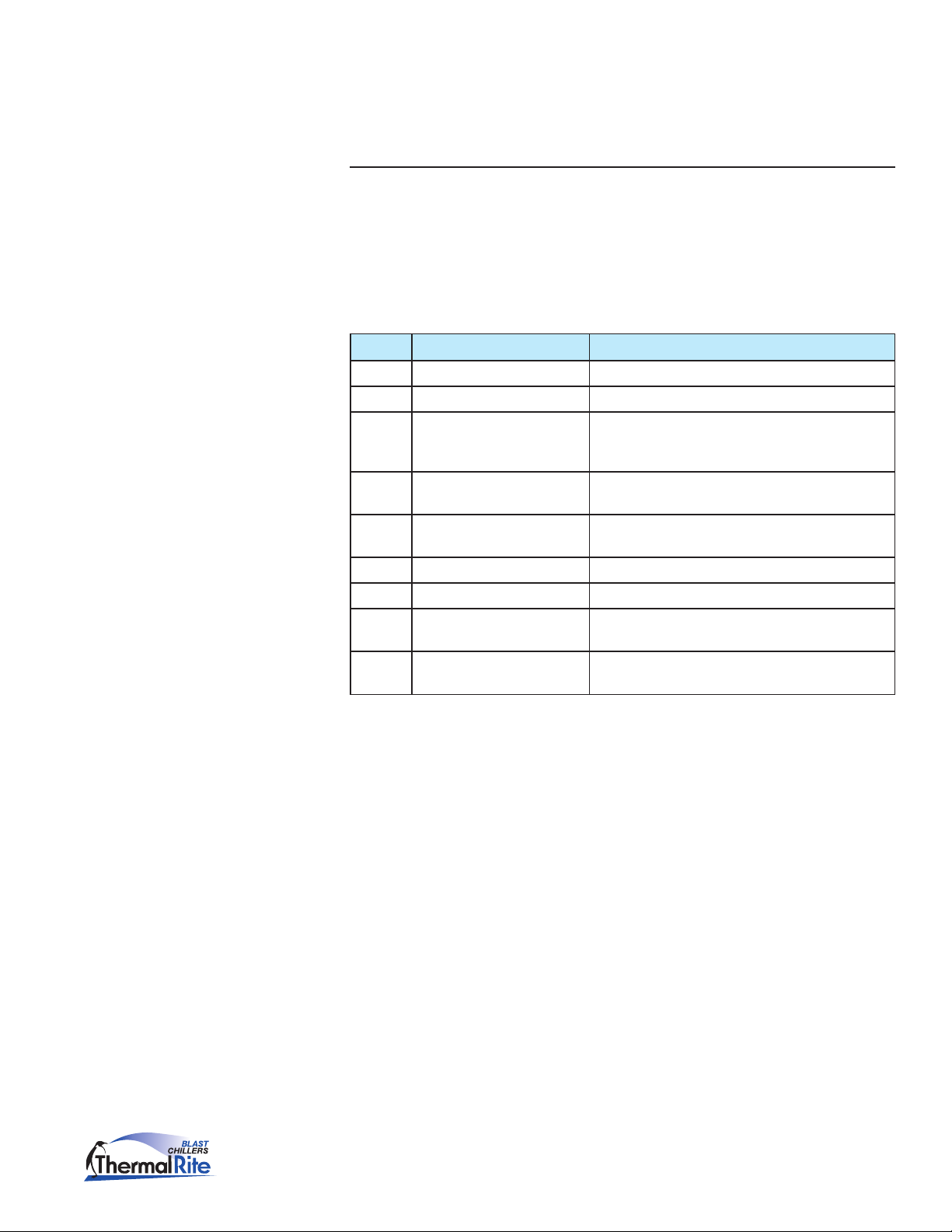
CODE CAUSE CONSEQUENCE
Er0 Chamber Probe Failure Does not allow unit to cycle. If running, cycle will stop.
Er1 Evaporator Probe Failure During storage cycle, evaporator fans do not run.
Er3 Needle Probe Failure Does not allow a needle probe set temperature cycle
to run. Unit will stop if running on needle probe set
temperature cycle.
HP High Discharge Pressure or Low
Suction Pressure 1
d-r Door is Open for More than P39 Compressor and condenser fan will stop. Evaporator fan
AH High Chamber Temperature None
AL Low Chamber Temperature None
Err Key Pad – Control Module
Communication Error 2
RES Power Failure During Cycle Cycle will restart when power is restored. Message will
1
The pressure switch in this model series provides a single output, open or closed. The circuit is
normally open and will close when either the High or Low Pressure limits are reached. In effect, the
failure code, HP, could mean either high discharge pressure as well as low suction pressure.
2
Additional troubleshooting at the Key Pad – Control Module connections:
Unit will not operate in any cycle. If running, compressor,
evaporator and condenser fans will stop.
will cycle according to P37
None
ash to indicate cycle has restarted.
• NoGroundconnection–Displayashesand/ordims
• NoNegative(-)connection–Displaymayworknormallywithoutfailure
code
• NoPositive(+)connection–FailureCodeErrorisdisplayed
• No12Vconnection–Displaywillnotlightup.
Customer Service: (800) 333-5653, www.thermalrite.com
9

ETL Blast Chiller Service Manual
Failure Code Details
Service Menu –
Conguration
Parameters
The HACCP feature provides the ability to get additional information such as
failure code, date of occurrence, min/max temperature (if applicable), and
duration of alarm condition. To access previous failure codes, press and hold
the PROGRAM key for 5 seconds. Use the UP and DOWN arrow keys to scroll
through the previous failure codes. Press the PROGRAM key to exit.
Entering the Conguration Parameters
This menu can only be accessed when the unit is in the OFF Mode.
1. Press and hold the UP and DOWN arrow keys at the same time for ve (5)
seconds.
PA – for password will be displayed in the upper display. No password is
needed.
2. Press either the UP or DOWN arrow key to scroll through the menu of
parameters.
3. To select a parameter that is being displayed, press the TIME key.
4. To change the value, press the UP or DOWN arrow key.
5. Press the TIME key to save any changes and return to Parameters Menu.
Parameter List (Factory Setting)
The following table shows the factory settings for both Blast Chiller (GBC) and
Shock Freezer (GBF) units.
Note: Selecting a freezing cycle on a GBC unit will run a normal chilling cycle
(Cabinet at 4°F, needle probe end cycle temperature at 37°F)
CODE U.O.M. GBC DESCRIPTION GBF
P0 - 0 unit of temperature measurement
0 = °F
1 = °C
P1 °F 4 cabinet probe offset 4
P2 °F 0 evaporator probe offset 0
P3 °F 0 needle probe offset 0
GROUP - - MAIN CONTROLLER -
P4 °F 20 operational setpoint during the second hard chill
step; also, operational setpoint during normal chilling
(with reference to the cabinet probe)
0
20
10
P5 °F -4 operational setpoint during freezing (with reference
Customer Service: (800) 333-5653, www.thermalrite.com
-40
to the cabinet probe)
ETL Blast Chiller Service Manual
Service Menu –
Conguration
Parameters
(continued)
CODE U.O.M. GBC DESCRIPTION GBF
P6 °F -4 operational setpoint during the rst hard chill step
(with reference to the cabinet probe)
P7 °F 37 operational setpoint during post-chill storage (with
reference to the cabinet probe)
P8 °F -4 operational setpoint during post-freeze storage (with
reference to the cabinet probe)
P9 °F 2 P4, P5, P6, P7 and P8 differential 2
P10 °F 37 set temperature chill end temperature (with
reference to the needle probe)
P11 °F 37 set temperature freeze end temperature (with
reference to the needle probe)
P12 °F 46 temperature at which the hard chill switches from
the rst step to the second (with reference to the
needle probe)
P13 °F 99 temperature above which it is not possible to start a
set-temperature operational cycle (with reference to
the needle probe)
P14 °F 9 needle probe and cabinet temperature differential for
verication of correct needle probe insertion
0 = the test will not be performed
-4
37
-4
37
0
46
99
9
P15 sec 60 duration of the second test to check correct needle
probe insertion; see also P14
P16 min 90 maximum set temperature chill duration; also timed
chill duration
P17 min 90 maximum set temperature freeze duration; also timed
freeze duration
P18 min 45 rst hard timed chill step duration 45
GROUP - - COMPRESSOR PROTECTIONS -
P19 min 0 compressor delay from device power on (from
restoration of power)
P20 min 0 minimum elapsed time period between two
consecutive compressor start-up operations
P21 min 0 minimum compressor shut-down time 0
GROUP - - DEFROSTING -
P22 - 1 defrost type
0 = electric (defrost on relay)
1 = hot gas (defrost compressor and relay on)
2 = air (evaporator fan on)
P23 °F 46 defrost end temperature (with reference to the
evaporator probe)
P24 min 10 maximum defrost duration 10
P25 hour 6 defrost interval during storage; see also P26
0 = intermittent defrosting will never be activated
(only the rst will be activated)
60
90
240
0
0
1
46
6
Customer Service: (800) 333-5653, www.thermalrite.com
11
ETL Blast Chiller Service Manual
Service Menu –
Conguration
Parameters
(continued)
CODE U.O.M. GBC DESCRIPTION GBF
P26 min 1 rst defrost delay from start of storage; see also P25 1
P27 - 1 defrosting at start of chilling and freezing
1 = YES
P28 min 2 drip-drain duration 2
P29 - 0 resetting of compressor protections at start of
defrosting (only if P22 = 1)
1 = YES
P30 sec 30 elapsed time between the defrost request and
switching on the compressor (only if P22 = 1 and
providing that the compressor is off when the defrost
is requested); see P31 (7) (8)also
P31 sec 0 elapsed time between the defrost request and
activation of the solenoid valve (only if P22 = 1
and on condition that the compressor is off when
defrosting is requested); see also P30
GROUP - - EVAPORATOR FAN -
P32 °F 37 temperature above which the evaporator fan is
switched off during storage (with reference to the
evaporator probe)
P33 °F 2 P32 differential 2
P34 - 0 evaporator fan activity during defrosting (only if P22
= 0 or 1)
0 = on
1 = off
P35 min 3 evaporator stop time after dripping 3
P36 °F 99 temperature above which the evaporator fan is
switched off (with reference to the cabinet probe)
1
0
30
0
37
0
99
P37 - 1 effect caused by activation of microport input on
evaporator fan
0 = no effect
1 = the evaporator fan will be switched off
GROUP - - DIGITAL INPUTS -
P38 - 1 microport input contact type
0 = NA (input active with contact closed)
1 = NC (input active with contact open)
P39 min 0 micro port input alarm delay 0
P40 - 1 high pressure input contact type
0 = NA (input active with contact closed)
1 = NC (input active with contact open)
P41 min 120 high pressure input alarm delay 120
P42 - 0 low pressure input contact type
0 = NA (input active with contact closed)
1 = NC (input active with contact open)
P43 min 0 low pressure input alarm delay 0
P44 - 0 compressor thermal protection input contact type
0 = NA (input active with contact closed)
1 = NC (input active with contact open)
1
1
1
0
0
12
Customer Service: (800) 333-5653, www.thermalrite.com
ETL Blast Chiller Service Manual
Service Menu –
Conguration
Parameters
(continued)
CODE U.O.M. GBC DESCRIPTION GBF
P45 min 0 compressor thermal protection input alarm delay 0
GROUP - - CABINET STERILISATION -
P46 min 5 UV light on duration (duration of cabinet sterilisation) 5
GROUP - - NEEDLE PROBE HEATING -
P47 °F 99 needle probe heating end temperature (with
reference to the needle probe)
P48 sec 15 maximum duration of needle probe heating 15
GROUP - - DOOR ELEMENTS -
P49 °F 41 the temperature, below which the door elements are
switched on (with reference to the cabinet probe)
P50 °F 4 P49 differential 4
GROUP - - CONDENSER FAN -
P51 - 1 condenser fan activity in the absence of the
condenser probe (P61 = 0)
0 = in parallel with compressor
1 = on
P52 °F 68 the temperature below which the condenser fan is
switched off in the presence of the condenser probe
(P61 = 1) and on condition that the compressor is on
(with reference to the condenser probe); see also P54
99
41
1
68
P53 °F 9 P52 differential 9
P54 sec 30 condenser fan switch off delay on switching off the
compressor in the presence of the condenser probe
(P61 = 1); see also P52
GROUP - - MISCELLANEOUS -
P55 sec 3 chill and freeze cycle completion buzzer duration 3
P56 sec 15 maximum buzzer duration during an alarm state 15
P57 sec 10 elapsed time between switching on the compressor
and pump down valve activation (pump down in
power up); also elapsed time between deactivation
of the pump down valve and switching off the
compressor (pump down in power down)
P58 - 0 defrost parameter units of measurement
0 = P25 h, P24, P26, P28 and P35 min
1 = P25 min, P24, P26, P28 and P35 s
P59 - 0 reserved 0
P60 - 0 probe type
0 = NTC
1 = PTC
P61 - 0 condenser probe enabling
1 = YES
30
10
0
0
0
Customer Service: (800) 333-5653, www.thermalrite.com
13

ETL Blast Chiller Service Manual
Service Menu –
Conguration
Parameters
(continued)
CODE U.O.M. GBC DESCRIPTION GBF
GROUP - - CONDENSER TEMPERATURE ALARMS -
P62 °F 99 the temperature above which the condenser
temperature alarm is activated (with reference to the
condenser probe)
P63 °F 18 P62 differential 18
GROUP - - CABINET TEMPERATURE ALARMS -
P64 °F -7 temperature below which the minimum temperature
alarm is activated during post-chill storage, with
relationtoP7,i.e.“P7+P64”(withreferencetothe
cabinet probe)
0 = no alarm
P65 °F 7 temperature above which the maximum temperature
alarm is activated during post-chill storage, with
relationtoP7,i.e.“P7+P65”(withreferencetothe
cabinet probe)
0 = no alarm
P66 °F 0 temperature below which the minimum temperature
alarm is activated during post-freezing storage, with
relationtoP8,i.e.“P8+P66”(withreferencetothe
cabinet probe)
0 = no alarm
P67 °F 0 temperature above which the maximum temperature
alarm is activated during post-freezing storage, with
relationtoP8,i.e.“P8+P67”(withreferencetothe
cabinet probe)
0 = no alarm
P68 °F 0 P64, P65, P66 and P67 differential 0
P69 min 25 storage operation start-up temperature alarm delay 25
P70 min 10 temperature alarm delay 10
GROUP - - DATA PRINTING -
P71 - 0 enable printing
1 = YES
99
-7
7
-7
7
0
14
P72 min 5 print interval 5
P73 - 0 HACCP alarm list deletion
P74 - 2 Baud rate
P75 - 2 Bit polarity
P76 - 1 Board address 1
Customer Service: (800) 333-5653, www.thermalrite.com
0
1 = YES
2
0=2400
1=4800
2=9600
3=19200
2
0=no polarity
1=even
2=odd
ETL Blast Chiller Service Manual
Service Menu –
Conguration
Parameters
(continued)
Temperature Probe Display
To check the reading of the unit’s temperature sensing probes, rst make sure
the unit is in the OFF mode.
1. Press the NEEDLE PROBE key and the DOWN arrow key together and hold
for ve (5) seconds.
2. To scroll through the reading use the UP or DOWN arrow key.
DISPLAY PROBE
Pr1 Cabinet Probe
Pr2 Needle Probe
Pr3 Evaporator Probe
Valuable information can be obtained by checking the evaporator probe when
the unit is struggling to reach the cabinet temperature setpoint, (i.e. -40°F).
This may indicate that the evaporator coil is not being supplied with sufcient
refrigerant.
With a cabinet setpoint of -40°F the actual evaporator temperature is
approximately -49°F at 0 PSIG. In this case, the controller evaporator probe
reading MUST BE at least -42°F, which is the minimum readable temperature.
Customer Service: (800) 333-5653, www.thermalrite.com
15
ETL Blast Chiller Service Manual
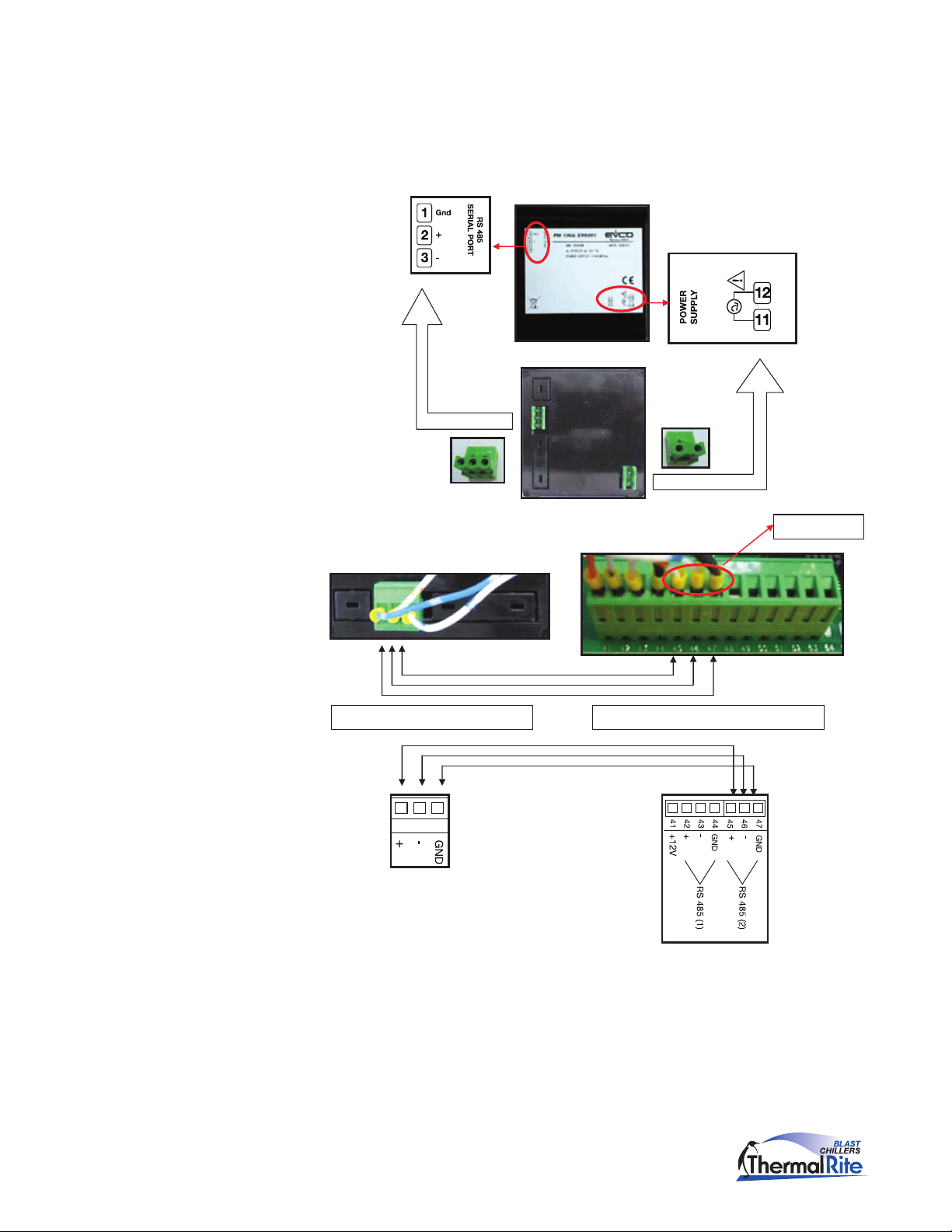
HACCP Printer
Blast Chillers can be ordered with an optional printer, or one can be installed as
a retrot. The printer has its own power supply connection (110VAC – 240VAC
50/60 Hz). The printer is connected to the Main Board at the second RS 485
connection port (shown).
A belden shielded cable (3 wires) must be used.
RS485 (2)
45 46 47
PRINTER TERMINAL BLOCK MAIN BOARD TERMINAL BLOCK
16
Customer Service: (800) 333-5653, www.thermalrite.com
ETL Blast Chiller Service Manual
HACCP Printer
(continued)
1. Connect the printer to the Main Board using coaxial shielded cables.
2. The main controller must be set to recognize the printer and enable
communication. Set conguration parameter P71 to 1 to enable the printer
port on the Main Board. In addition, ensure that the following parameters
are set as shown:
P76 – 1
P75 – 2
An LED on the printer will indicate its status: RED = ON.
4. Press the feed key to output blank paper in either ON or OFF status.
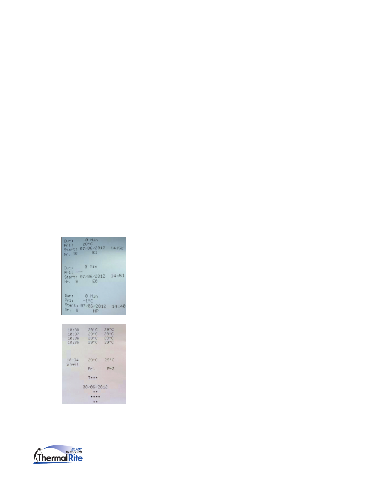
Printing Alarm List
To print the alarm list, the controller must be in the OFF mode.
1. Press the PROGRAM key for ve (5) seconds.
If the printer communication has been enabled, the rst display shown is
“Prt”.
2. To print the alarm code, press the PROGRAM key.
3. To exit from printing, press either the UP or DOWN arrow key and the alarm
list will be shown in the display.
The controller will only save the previous 10 alarms.
Printed codes will be as shown:
• Alarmduration
• Max/MinTemperature
• Date/Time
• AlarmCode
Printing Cycle Data
With the HACCP printer, it is also possible to print data history related to the
freezing and chilling cycles.
If the printer is left ON and a cycle is started, the data will be captured. Data
capture frequency is set in Parameter P72 (example: If P72 = 1, device will print
every minute) and give the following information:
• Typeofcycle
• Startdateandtime
• Time,CabinetandNeedleProbetemperatures(eachcaptureline)
Customer Service: (800) 333-5653, www.thermalrite.com
17
ETL Blast Chiller Service Manual
HACCP Printer
(continued)
Legend – Type of cycle:
Cycle code Description
T* Needle probe soft chilling
T*** Needle probe freezing
T>>>* Needle probe hard chilling
t* Time soft chilling
t*** Time freezing
t>>>* Time hard chilling
P1……..99 Programmed cycle
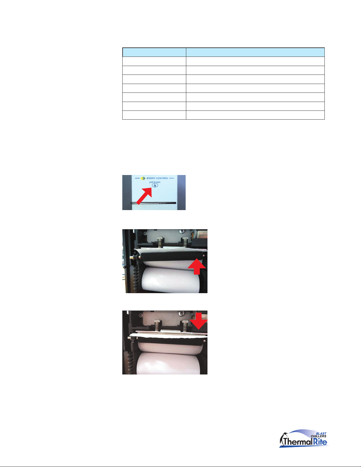
Replacing the printer paper
1. Press on the printer front cover as indicated. The cover will open allowing
access to the paper roll.
2. Pull the paper roll to one side to remove.
3. Insert the new paper roll.
4. Thread the paper between the rollers.
18
5. Reset roller and close the cover.
Customer Service: (800) 333-5653, www.thermalrite.com
ETL Blast Chiller Service Manual
Section 2 Troubleshooting
WARNING: Before performing any service that involves electrical
connection or disconnection and/or exposure to electrical components,
always follow the Electrical LOCKOUT/TAGOUT Procedure. Disconnect
all circuits. Failure to comply can cause property damage, injury or
death.
If, upon rst inspection, the cause of a problem is not obvious, a more thorough
troubleshooting may be necessary. The unit may need to be unplugged or
otherwise removed from the power supply so the internal components can be
tested.
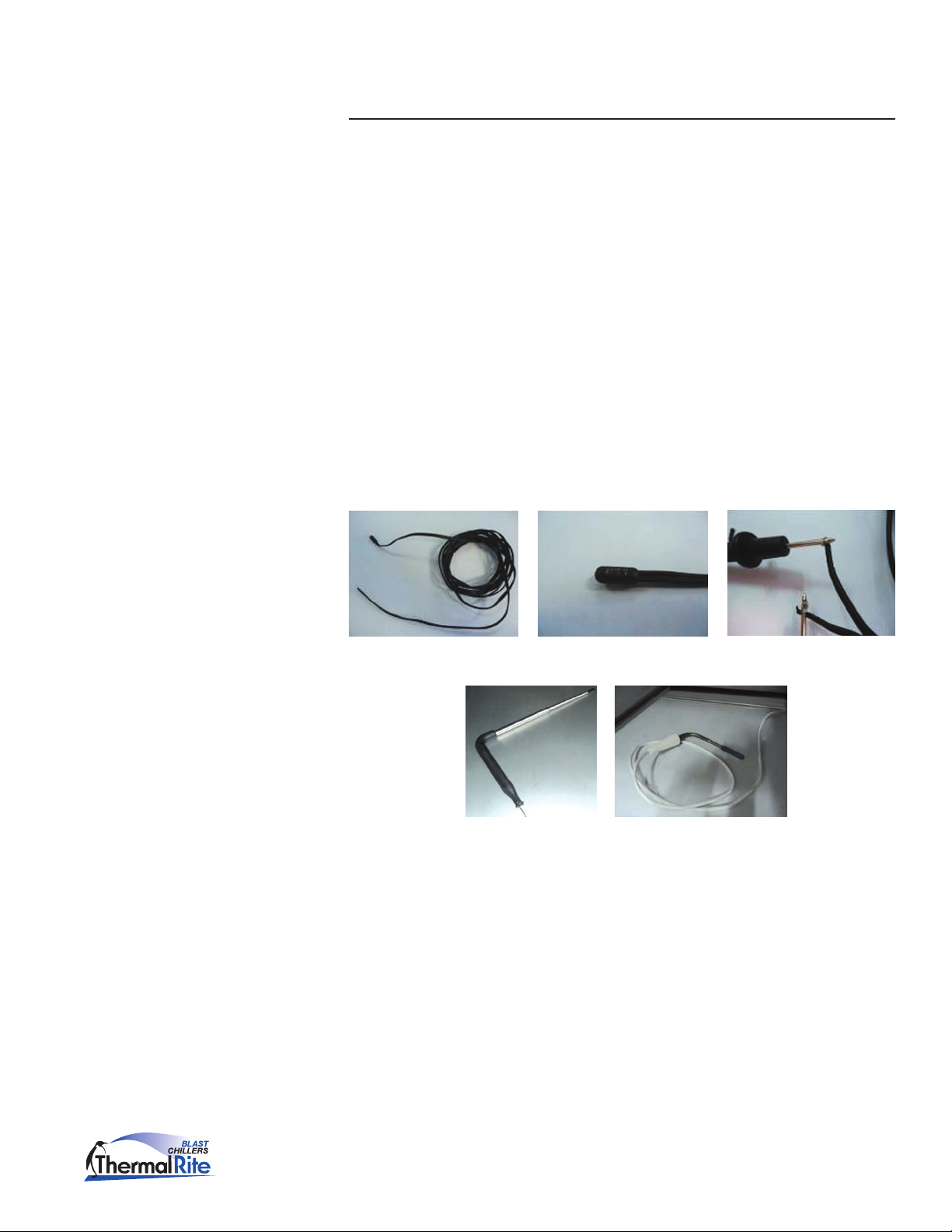
Probes
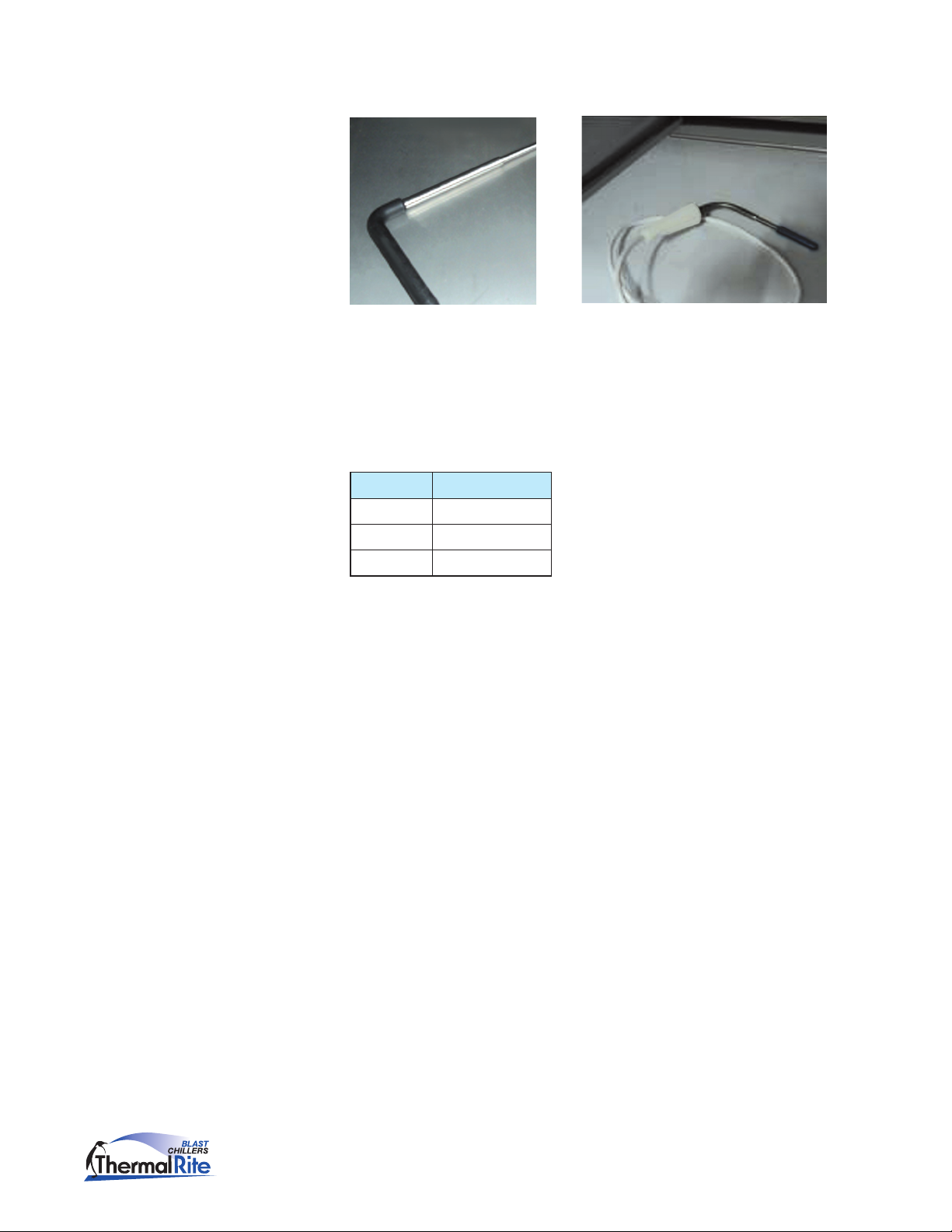
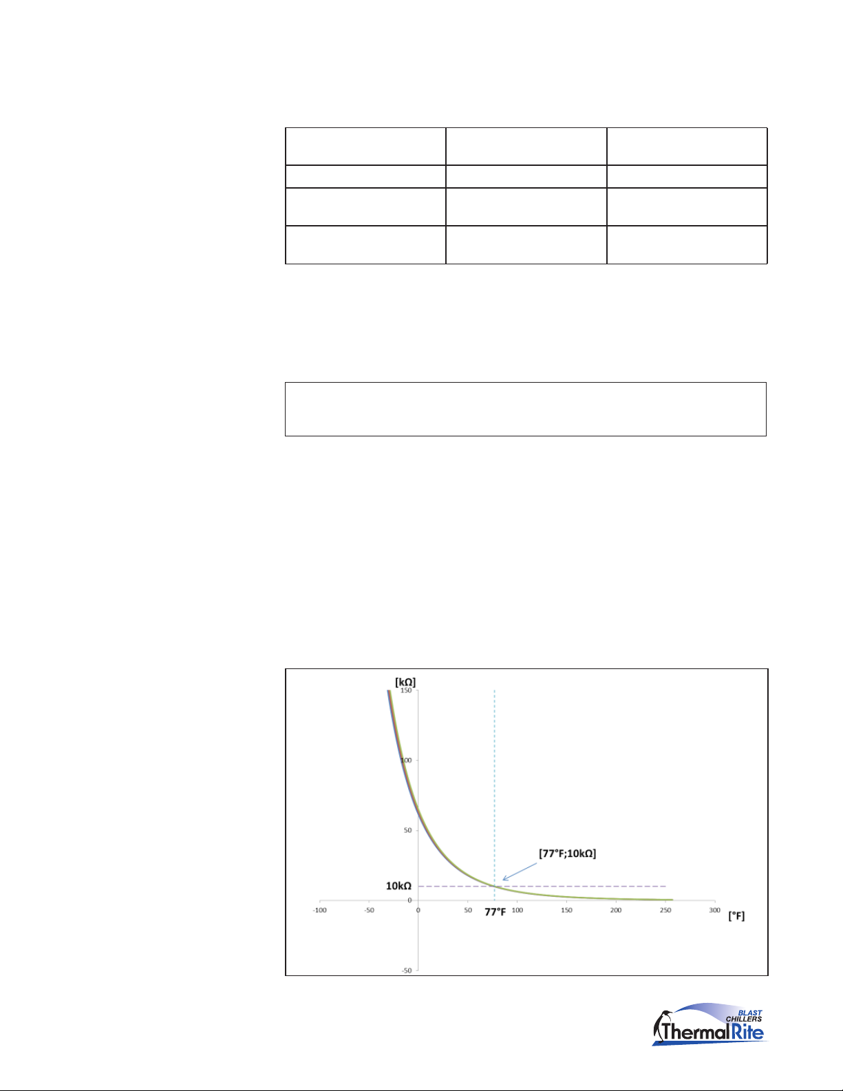
The Blast Chiller is equipped with several temperature sensing probes. These
probes are Negative Temperature Coefcient (NTC) thermoset sensors. The
chamber and evaporator probes have the same conguration.
NTC Probe
Bulb Probe Measuring
NTC Needle Probe Types
The needle probe has a different sensing element. Both types of probes have the
same resistance to temperature correlation.
Checking the Probes
When a Probe alarm occurs, it means there is something wrong with the sensor
reading. The problem may be in either the sensor wires or the sensor itself.
Probe alarms Er0, Er1, and Er3 are commonly due to an interrupted (open) circuit
in the wires.
The cause may be a short to the chassis or the two leads shorting together.
Customer Service: (800) 333-5653, www.thermalrite.com
19
ETL Blast Chiller Service Manual
Probes (continued)
To nd the cause of the alarm, disconnect the indicated probe and check the
resistance between the two wires.
If the Ohm reading is 0 Probe circuit is shorted between
the two wires
Ohm reading is innity, ∞ Probe is open Replace the probe
Reading matches the resistance
chart at a known temperature
Reading is not 0 or ∞ and does
not match the resistance chart
Probe is good Another problem is the cause
Probe is out of range Replace the probe
Replace the probe
If none of these choices is the case:
Ohm out each wire to the chassis. If the reading is 0 or anything less than
∞, the
probe is shorted to the chassis and must be replaced.
Note: A spare probe can be used in place of the suspected one. If the alarm
continues, the problem is something other than the probe.
The problem could also be in the probe connection to the Main Board.
Check for corrosion, water, loose or missing connections.
The problem could also be a result of an internal failure on the Main Board. If
all previous probe troubleshooting has not found the problem and the alarm still
occurs, replace the Main Board.
Probe Resistance Graph and Chart
Resistance Graph
20
Customer Service: (800) 333-5653, www.thermalrite.com
 Loading...