

ThermalRite Blast Chiller GBC-5G Installation Manual

1.GENERAL DOCUMENTATION
MODEL
NUMBER OF
TRAYS
MODEL
NUMBER OF
TRAYS
GBF-3GN2/3
3
GBC-20GN2/1
20
GBC-5G
5
GBC-40GN2/1
40
GBC-7
7
GBF-20GN2/1
20
GBF-10
10
GBF-40GN2/1
40
GBF-12GN2/1
12
GBF-20GN2/1
20
GBC-15
15
GBF-40GN2/1
40
GBC-18
18
GBF-12GN2/1
12
GBF-5P
5
GBF-23GN1/1
23
GBF-5G
5
GBF-12GN2/1RCV
12
GBF-7
7
GBF-20GN1/1T
20
GBF-15
15
GBF-20GN1/1CV
20
GBF-18
18
GBF-20GN1/1RT
20
GBF-5P+
5
GBF-23GN1/1+
23
GBF-5G+
5
GBF-12GN2/1RCV+
12
GBF-7+
7
GBF-20GN1/1T+
20
GBF-10+
10
GBF-20GN1/1CV+
20
GBF-15+
15
GBF-20GN1/1RT+
20
GBF-18+
18
The present manual is exclusively valid and applicable to the following products series:
European series

United states series
MODEL
NUMBER OF
TRAYS
MODEL
NUMBER OF
TRAYS
GBF-3GN2/3-ETL
3
GBC-20GN2/1-ETL
20
GBC-5G-ETL
5
GBC-40GN2/1-ETL
40
GBC-7-ETL
7
GBF-20GN2/1-ETL
20
GBF-10-ETL
10
GBF-40GN2/1-ETL
40
GBF-12GN2/1-ETL
12
GBF-20GN2/1+ETL
20
GBC-15-ETL
15
GBF-40GN2/1+ETL
40
GBC-18-ETL
18
GBF-12GN2/1+ETL
12
GBF-5P-ETL
5
GBF-23GN1/1-ETL
23
GBF-5G-ETL
5
GBF-12GN2/1RCV-ETL
12
GBF-7-ETL
7
GBF-20GN1/1T-ETL
20
GBF-15-ETL
15
GBF-20GN1/1CV-ETL
20
GBF-18-ETL
18
GBF-20GN1/1RT-ETL
20
GBF-5P+ETL
5
GBF-23GN1/1+ETL
23
GBF-5G+ETL
5
GBF-12GN2/1RCV+ETL
12
GBF-7+ETL
7
GBF-20GN1/1T+ETL
20
GBF-10+ETL
10
GBF-20GN1/1CV+ETL
20
GBF-15+ETL
15
GBF-20GN1/1RT+ETL
20
GBF-18+ETL
18
1.1General information
• This manual is an integral part of the
product, providing all the information
required to ensure correct installation,
operation and maintenance of the machine.
• Read the manual carefully, making
reference to it for machine operation. Keep
the manual in a safe place where it can
be accessed by all authorised operators
(installers, operators and service
personnel). The european series machines
are been constructed in compliance with
the directives 73/23/CEE (low-voltage),
89/336/CEE (electromagnetic compatibility)
and 98/37/CE (machines; for certain
models only), while, the United states
series machines are been constructed in
compliance with the standard for Safety
Commercial Refrigerators and Freezers,
ANSI/UL 471, Issued: 2006/01/27 Ed:9
Rev:2008/10/24; Refrigeration Equipment
General Instruction No 1-2 (R2004);
CAN/CSA-C22.2 No.120, Issue:1991/01/01
Ed:3; Commercial Refrigerators and
Freezers, NSF/ANSI 7, Issue: 2007/06/01.
• The machine has been designed for
professional applications only and should
only be operated by qualified personnel.
• The machine must only be used for the
purposes for which it was designed, i.e.
for chilling and freezing food products.
The machine must not be used for products
requiring constant temperature control
and recording, such as:
- heat-sensitive chemicals,
- medicines or
- blood products.
• The manufacturer declines all
responsibility for any damage caused by
incorrect or unreasonable machine use,
such as:
• improper use by untrained persons;
• technical modifications or operations
not suited to specific models;
• use of non-original or non-specific spare
parts;
• failure to follow the instructions given in
this manual.
1.2 Installation
The machine must be installed by a
specialised technician authorised by and in
compliance with the instructions given in
this manual. In the event that the machine
is fitted with a remote condenser unit, the
installation technician is responsible for
checking all connections in compliance with
the instructions given by for plant and
machine installation.
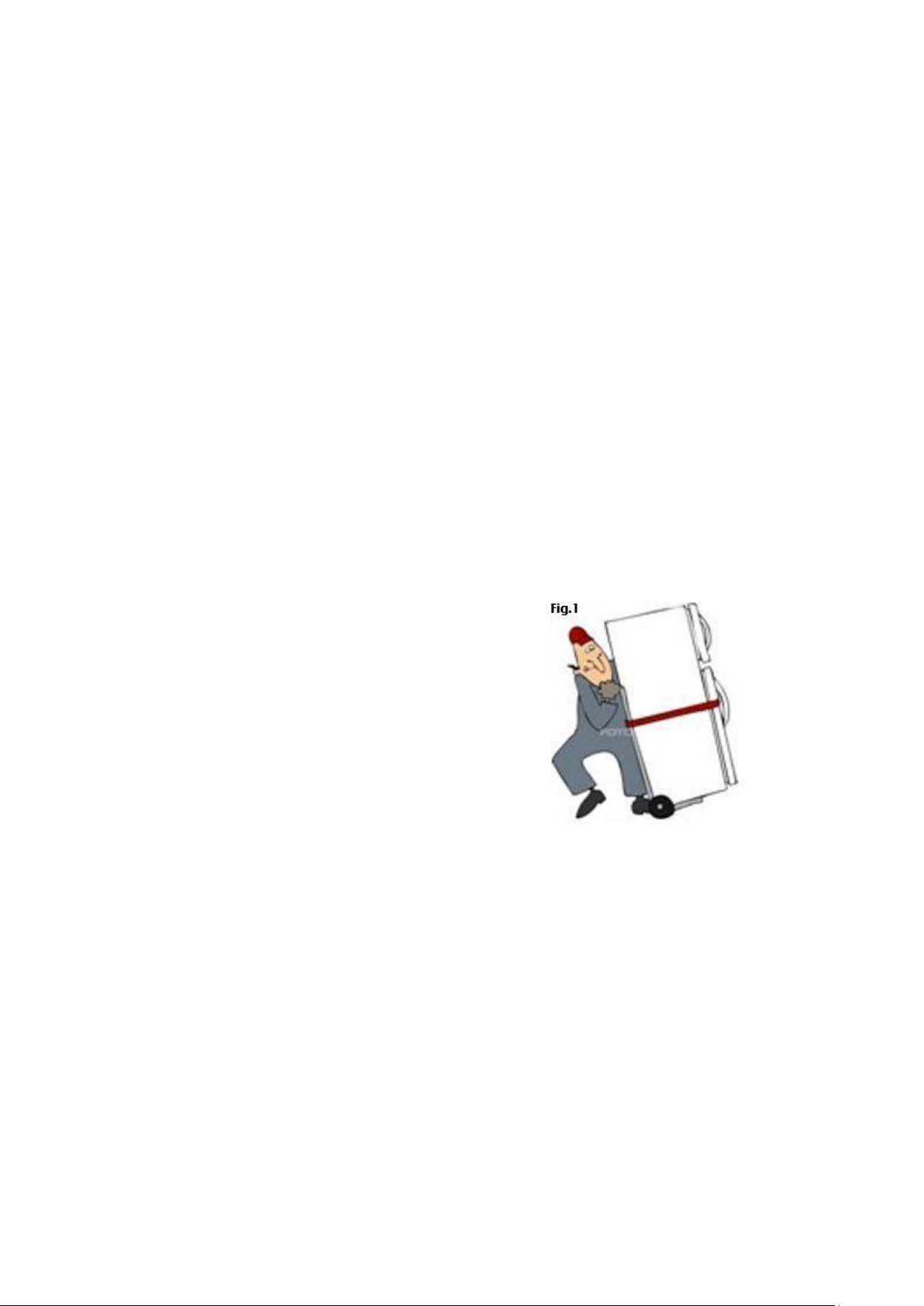
1.3 Transport and handling
• To load or unload the machine and/or
components from/onto the means of
transport, use a lift truck or fork lift
equipped with forks that are at least half
the length of the machine housing; use a
crane if the machine is fitted with eye
bolts. Select the lifting equipment suited
to the weight and overall dimensions of
the packaged machine/components.
• When handling the machine/ components,
apply all precautions to prevent
damage, in compliance with the information
given on the packaging material (fig.1).
1.4 Unpacking
• Remove all cardboard, wood or other
materials from the wood base on which
the machine is set. Lift the
machine/components with suitable means
(e.g. lift truck), remove the wood base, then
position the machine/components in the
allocated site.
• Once all packing material has been
removed, check that the machine has
not been damaged in any way.
• Remove the protective PVC film on the
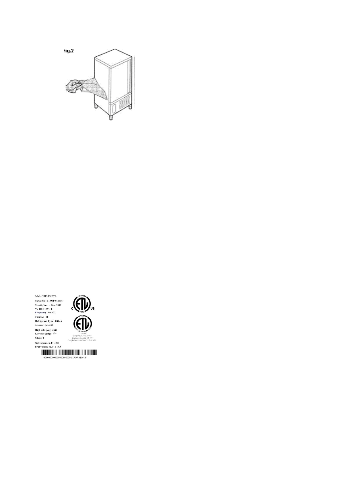
stainless steel panels from all internal and
external surfaces (fig. 2).
• Always wear protective gloves when
handling
packing material and the wood base.
• NB Dispose of packing materials in
compliance
with disposal regulations applied
in the country where the machine is to be
installed. Never dispose of materials in
the environment.
1.5 General safety regulations
Failure to observe the recommendations
made by the present manual will be at the
entire responsibility of the machine user.
The main safety regulations are as follows:
- do not touch the machine with moist
or wet hands or feet;
- never operate the machine while
barefoot;
- do not insert screwdrivers, cooking
utensils or any other object between
the guards and moving parts;
- before performing cleaning or routine
maintenance operations, disconnect
the machine from the power supply at
the master switch and the main knife
switch (if present);
- never pull on the power cable to
disconnect the machine from the power
supply.
2.1 Data plate information
• Check that the data specified on the
plate correspond to the characteristics
of the power supply (V, kW, Hz, no. phases
and power available).
• The dataplate with appliance (fig.3)
specifications is located at the rear exterior
of the machine and/or on the electrical
boards The set-up of individual units and
the installation of condensers are subject to
the fire-safety regulations of the country in
which the machine is installed; seek all
necessary advice from the local firefighting
authorities. Bear in mind that the
intervention of safety valves or plug fuses in
the refrigerating circuit will lead to the
immediate discharge of refrigerant into the
environment.
2.2 Positioning
• The machine must be installed and
commissioned in complete compliance with
safety regulations, procedures and standing
laws.
• The installation technician bears the
responsibility of ensuring compliance with
fire safety requirements; seek all necessary
advice from the local firefighting authorities.
• Position the machine in the allocated site.
• Adjust the machine feet until the appliance
is perfectly level. In the case of particularly
heavy equipment, use appropriate lifting
means
2.INSTALLATION
• If the appliance is not perfectly level,
correct operation and condensate flow-off
will not be assured.
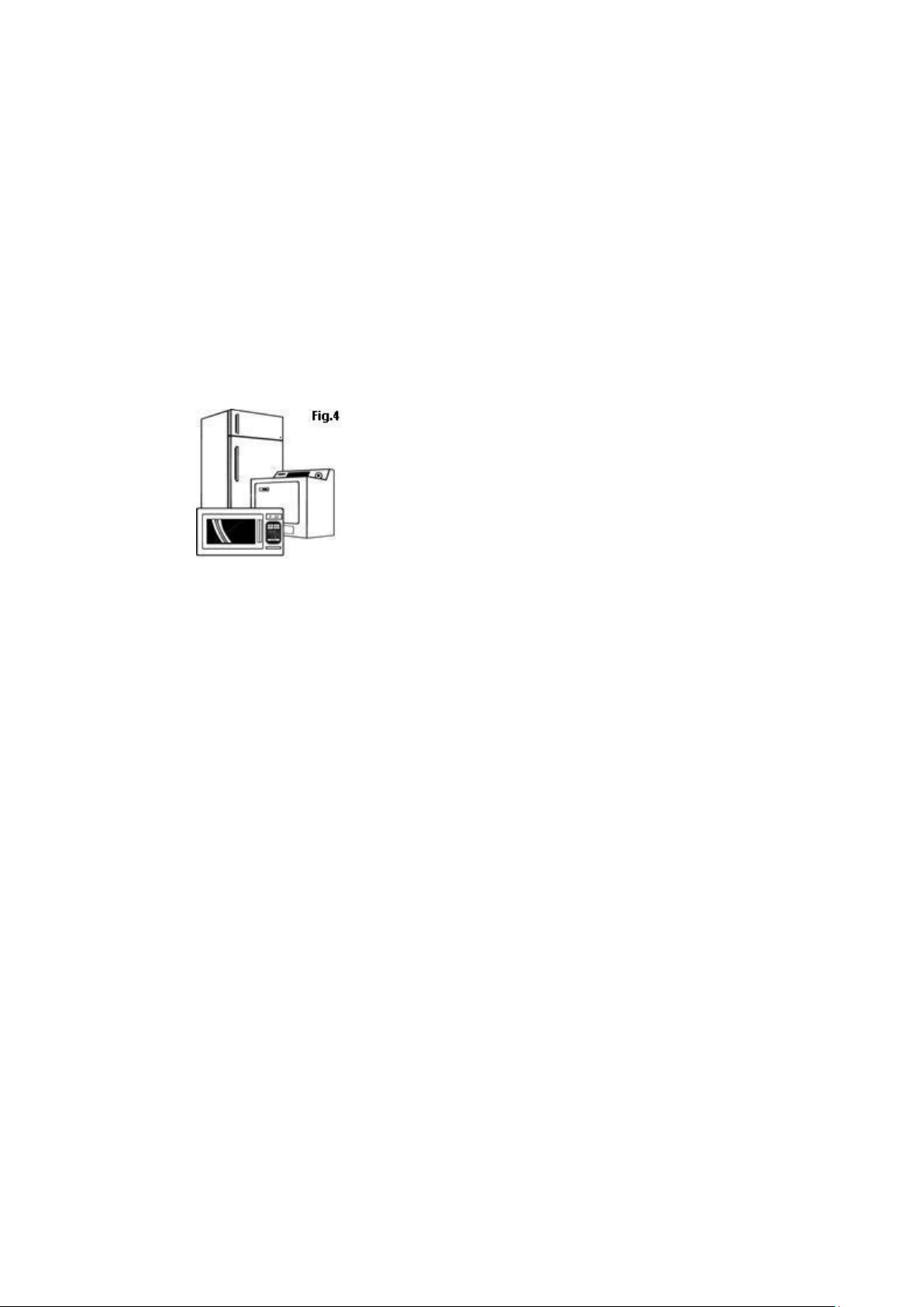
AVOID
• direct exposure to sunlight;
• closed sites with high temperatures and
poor air circulation;
• installing the machine near sources of
heat (fig. 4).
2.3 Ambient temperature and air
circulation
For air-cooled appliances, the maximum
ambient temperature for operation is 32°C.
Correct operation cannot be guaranteed at
higher temperatures. The machine may
operate safely to a maximum temperature
of 38°C. Remote condensing units must be
installed in special rooms or outdoors,
protected against direct sunlight by a
shelter or roof structure (at the cost of the
purchaser)..
Sufficient air circulation must be guaranteed
at all times
2.4 Electrical connections
A dedicated thermal-magnetic circuit
breaker compliant with established
regulations must be installed on the
appliance power line.
• Connected electrical cables must
correspond to the technical data (as
specified on electrical drawings provided by
the installation technician). Connect the
grounding conductor to an efficient
grounding system.
THE MANUFACTURER DECLINES ALL
LIABILITY AND GUARANTEE
OBLIGATIONS IN THE EVENT OF
INJURY TO PERSONS OR DAMAGE TO
EQUIPMENT AND OBJECTS DUE TO
INCORRECT INSTALLATION AND/OR
FAILURE TO COMPLY WITH STANDING
INSTALLATION REGULATIONS.
2.5 Refrigeration component
connections - remote assemblies
Appliance power lines are sized for
installation distances of up to 5 metres. For
greater distances, seek advice from .
2.6 Information for the installation
Technician
Before starting up the machine, check that
it has been correctly installed and
commissioned (test report).
1. Check that there are no gas leaks from
weldings or joints made during installation
works.
2. Check that the pipes connecting the
condenser to the remote condensing
unit have been well insulated.
3. Check all wiring connections.
4. Check electrical input.
5. Check the standard pressure in the
refrigerant system.
.

6. check the expansion valve during
operation.
7. Perform at least one blast freezing cycle
(to the SET temperature) and one manual
defrosting cycle
In the event that the appliance or the
remote condensing unit have not been
transported in a vertical position (e.g. on
the back) or have been overturned during
installation works, allow at least 4 hours
before starting up the equipment.
• Inform the customer of the exact purpose
of the appliance, with specific reference
to the use and requirements of the
customer.
The appliance must be installed and put
into service by a technician authorised.
2.7 Safety and control systems
• Door micro switch: shuts down fan
operation in the cell when the door is
opened.
• General fuses: protect the power circuit
against short circuiting and overloads.
• Compressor heat relay: intervenes in the
event of overloads or operating faults.
• Safety pressure switch: intervenes in the
event of excessive pressure in the
refrigerant circuit.
• Plug fuses: intervene in the event of
overpressure or operating fault in the safety
pressure switch (see above).
• Chamber temperature control: operated
by the electronic board by means of a
probe inside the cell.
• Temperature control end defrost cycle:
controlled by the electronic board by
means of the probe in the evaporator
.
2.8 Appliance disposal
Demolish and dispose of the machine in
compliance with the regulations applied in
the country of installation, particularly in
regards to refrigerant gas and compressor
lubricant oil.
WEEE Notice
The Directive on Waste Electrical and
Electronic Equipment (WEEE), which
entered into force as European law on 13th
February 2003, resulted in a major change
in the treatment of electrical equipment at
end-of-life. The purpose of this Directive is,
as a first priority, the prevention of WEEE,
and in addition, to promote the reuse,
recycling and other forms of recovery of
such wastes so as to reduce disposal.
The WEEE logo on the product or on its box
indicates that this product must not be
disposed of or dumped with your other
household waste. You are liable to dispose
of ali your electronic or electrical waste
equipment by relocating over to the
specified collection point for recycling of
such hazardous waste. Isolated collection
and proper recovery of your electronic and
electrical waste equipment at the time of
disposal will allow us to help conserving
natural resources. Moreover, proper
recycling of the electronic and electrical
waste equipment will ensure safety of
human health and environment. For more
information about electronic and electrical
waste equipment disposal, recovery, and
collection points, please contact your local
city centre, WEEE professional disposal
service, shop from where you purchased
the equipment, or manufacturer of the
equipment.
3. ADVICE TO ENSURE EFFICIENT APPLIANCE
3.1 Shut-down procedures
In the event of emergency, shut down the
appliance by switching off power at the
main panel, by means of the knife switch or
by removing the plug from the power
socket.
3.2 Operating tips
Before starting up the appliance, clean the
inside of the cell thoroughly.
3.3 Pre-cooling
Before using the appliance for the first
time, or after a prolonged period of disuse,
pre-cool the cell by running an empty
cycle until the set operating temperature
has been reached. To ensure optimal
performance without any alteration to food
quality: arrange food products in such a
way as to favour the circulation of cold air
throughout the cell; open the door as little
as possible.
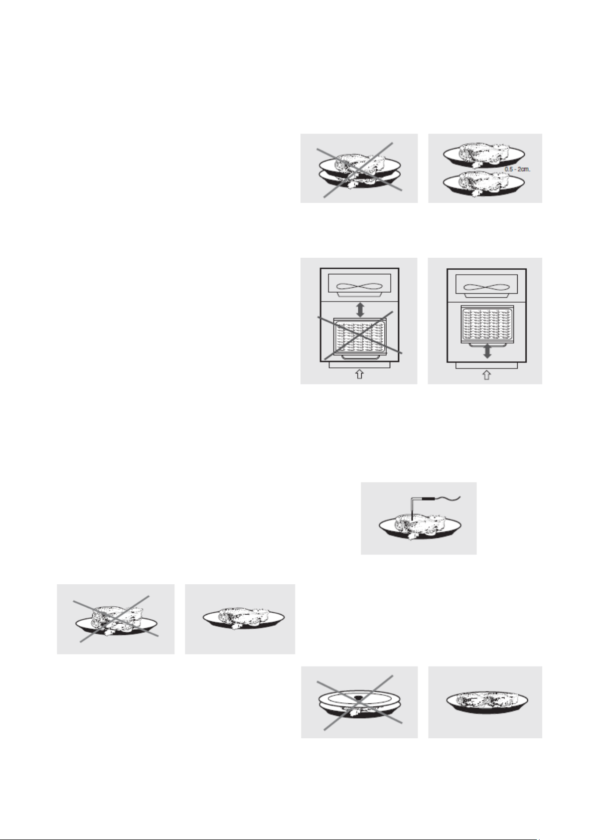
3.4 Loading the appliance
a) Ensure that foods to be chilled and/or
frozen are separate and do not have a
thickness greater than 50-80 mm. Do not
load the appliance beyond the quantity by
the manufacturer.
b) Ensure that there is sufficient clearance
between trays to enable free air circulation.
If the appliance is not completely full,
distribute the trays and foods evenly
throughout the available space.
c) Position trays inside the tray
compartment
as far as they will go, as close as
possible to the evaporator.
d) Position the core probe at the centre of
the largest product or food item; make
sure that the tip of the probe does not
protrude or touch the tray.
The probe must be cleaned and sanitised
before each new cycle (operation)
to prevent inadvertent contamination.
e) Avoid covering the trays and/or
containers
with insulating covers or film. The
more the product is insulated, the more
time is required for chilling or freezing.
Trays must be packaged when the product
has been chilled, before being
placed in storage.
OPERATION
4.PROGRAMMING AND OPERATING INSTRUCTIONS
Please read these instructions carefully prior to installation and use, and follow all the
precautions for installation and electrical connections; keep these instructions with the
device for future consultation.
The device must be disposed of in accordance with local regulations pertaining to the
collection of electrical and electronic appliances.
4.1 Introductory information
The device has the following operational states:
•"on" (the device is switched on and an operating cycle is running)
•"stand-by" (the device is switched on and no operating cycle is running, but it is
possible to select one)
•"off" (the device is switched on and no operating cycle is running, and it is not
possible to select any).
If power is interrupted while in the "on" mode, when power is restored the device will be in
the same state and the operational cycle will be restarted from the point reached when the
power interr. occurred .
If power is interrupted while in "stand-by" or "off" mode, when power is restored the device
will be in the same state.
4.2 Switching the device on/off ("off"/"stand-by")

•ensure no procedures are running
•press B1 for 5 s
The regulators are switched off while in "off" mod.
4.3 Starting/stopping an operational cycle ("on"/ "stand-by")
•ensure no procedures are running
•press B1
The regulators are switched off while in "stand-by" mode.
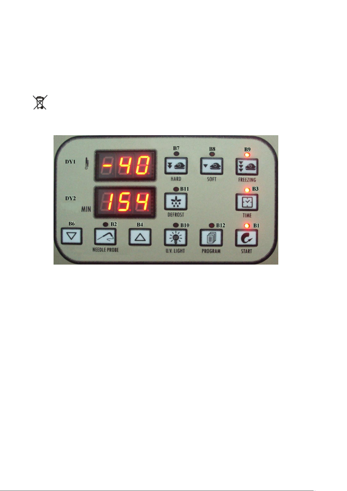
4.4 The display
In the "on" state, during normal operation, display DY1 shows:
•the temperature measured by the needle probe if a set-temperature chilling or
freezing operation is ongoing
•the temperature of the cabinet if a set-temperature chilling, or timed freezing or a
storage operation is ongoing.
Display DY2 shows:
•the amount of time for a blast chill or freezing operation, if these are ongoing
While in "stand-by" mode, display DY1 shows the cabinet temperature and display DY2
shows "- - -".
While in "off" mode, display DY1 shows "OFF" and display DY2 is off.
4.5 Displaying the temperatures detected by the probes
•ensure the device is in "off" mode and no procedures are running
•press B2 + B4 for 5 s: display DY1 will show the message "Pr1" and
display DY2 will show the cabinet temperature
•press B4 or B6 to select one of the labels shown in the table below.
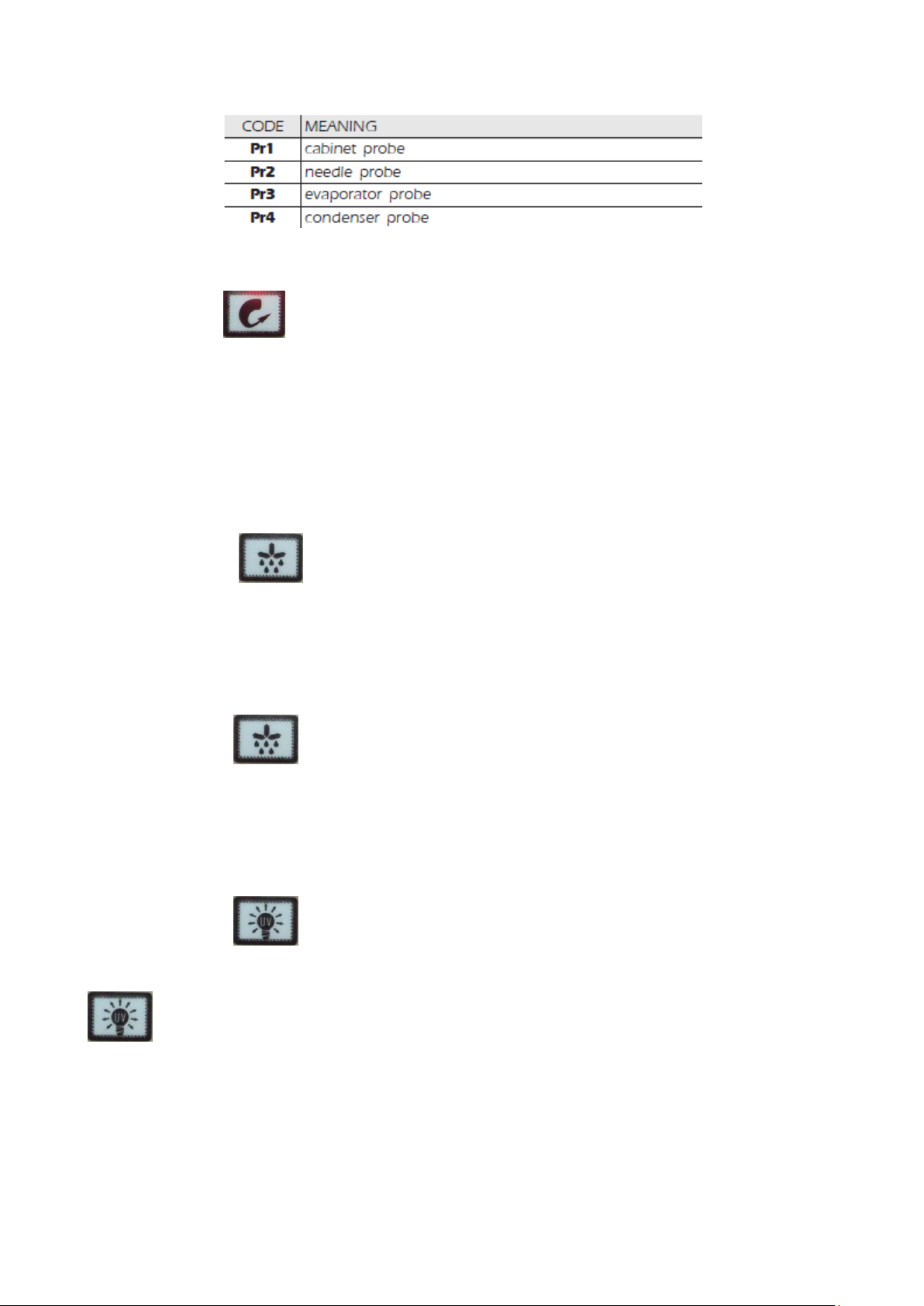
To exit the procedure:
•press B1
If there is no condenser probe (parameter P3 = 0), label "Pr4" will not be displayed.
4.6 Starting/stopping manual defrosting
To start defrosting in manual mode:
•ensure the device is in "off" mode and no procedures are running
•press B11 display DY1 will show “dEF”.
If the evaporator temperature is above the value set by parameter P23, defrosting will not
be activated.
To stop defrosting in manual mode:
•press B11
4.7 Switching on the UV light (cabinet sterilisation)
•ensure that the device is in "stand-by" mode, that no procedures are running and
that the micro port input is not active
•press B10
The UV light is turned on for the period of time established by parameter P46 or until B10
is pressed once more.
4.8 Heating the needle probe
•ensure that the device is in "stand-by" mode, that no procedures are running and
that the micro port input is not active

•press B2 for 5 s: the needle probe will be heated until it reaches the
temperature set by parameter P47 or at most for the period of time set by parameter
P48.
If the temperature detected by the needle probe is above the value set by parameter P47,
heating will not be started.
The micro-port input will not be reported during needle probe heating.
4.9 Buzzer mute
•ensure no procedures are running
•press B4
After the period of time established by parameter P56 has elapsed, the buzzer is
automatically muted.
5. OPERATIONAL CYCLES
5.1 Introductory information
The device has the following operational cycles:
•hard set-temperature chilling and storage
•normal set-temperature chilling and storage
•set-temperature freezing and storage
•hard timed chilling and storage
•timed normal chilling and storage
•timed freezing and storage.
Set-temperature cycles are preceded by a test to check correct needle probe insertion
(see parameters P14 and P15); if the result of the test is negative, cycles will be started in
timed mode.
5.2 Hard set-temperature chilling and storage cycle
To select the cycle:
•ensure the device is in "off" mode and no procedures are running
•press B7 : display DY1 will show the operational set point and LED B7 will
switch on.
 Loading...