

Page 1

Thermalright
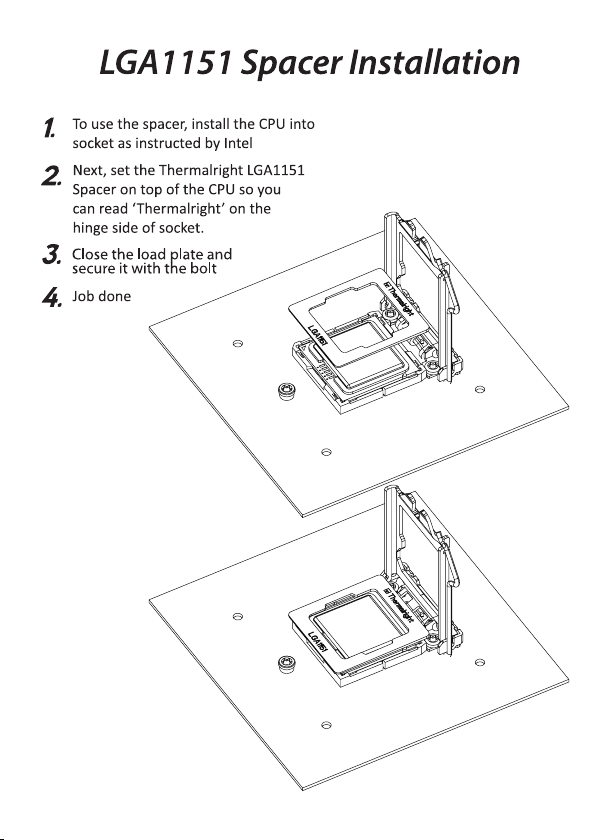
TRUE Spirit 90 Direct
Page 2
Page 3
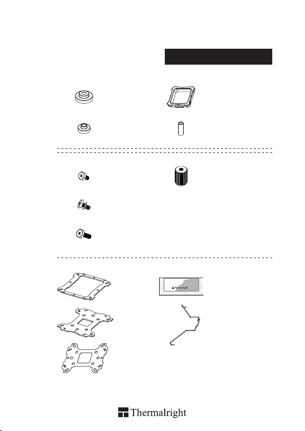
TRUE Spirit 90 Direct
× 4 × 1
Assembly package
× 4 × 8
× 5
× 3
× 5
× 1 × 1
× 1
× 1
Chill Factor
× 4
2g
× 4
4
4
8
Page 4
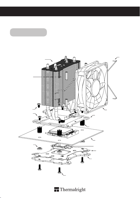
TRUE Spirit 90 Direct
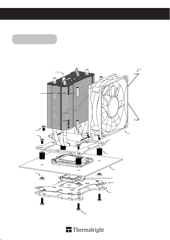
Intel 775/1150/1151/1155/1156/1366
Exploded View
Important! Before proceeding with installation, please check for the most
up-to-date instructions at www.thermalright.com
Rubber Tubes
M3L7 Screw
M3L6 Screw
Intel Washer
(small)
1
Heatsink Body
M3L10 Screw
Anchoring Mount
Screw Nut
Motherboard
Back Plate Cap
Mylar Film
Metal Back Plate
Fan Clip
TY-9225B
Page 5

Component
1
2
4 5 76 8
9
13
TS-90 Direct
1
Heatsink Body ×1
Screw Nut ×4
4 5 6
M3 L6 Screw ×5
7 8
Backplate Cap ×1
10
TY-9225B ×1
13
14
1110 12
Anchoring Mount ×1
2
Intel Washer (small) ×4
Fan Clip ×4
11
Mylar Film ×1
14
15
3
9
12
15
3
Chill Factor
Metal Back Plate ×1
M3L10 Screw ×5M3L7 Screw ×3
AMD Washer (big) ×4
Thermal paste ×1
Rubber Tubes ×8
2g
The Ultimate Cooling Solutions!
www.thermalright.com
2
Page 6
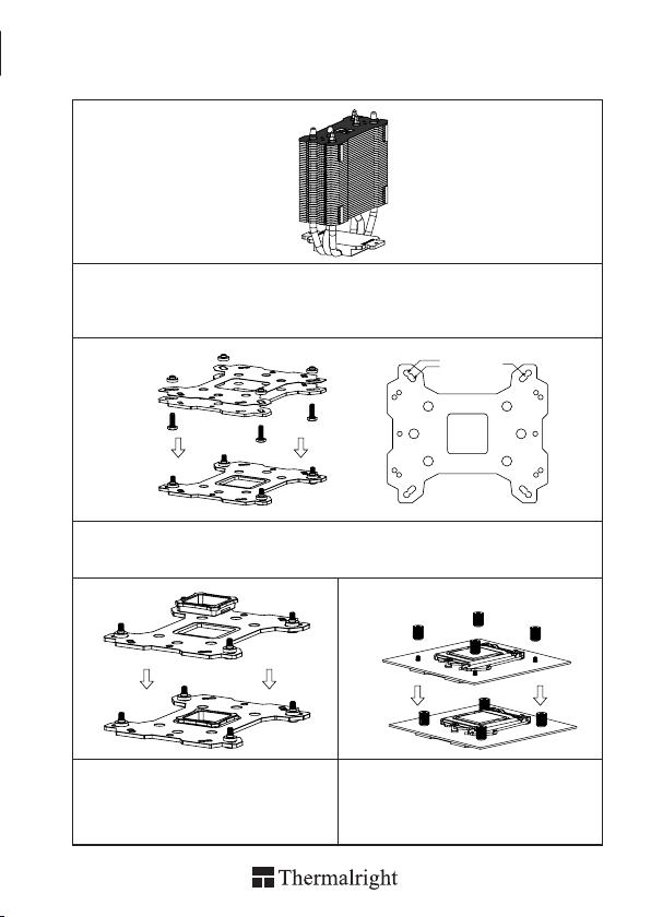
Installation Instructions:
Step 1:
Step1 : Rubber Tubes Installation
Insert the four black Rubber Tubes (Noise damping use) into the four indents on the front of the heat-sink
body. Do not remove them.
Step 2:
Step 2 : Backplate Installation
Choose the platform (775/1150/1151/1155/1156/1366) you are in use. Make four M3L10 Screw Pillars
go through the Metal Back Plate and the Mylar lm from bottom towards top.And then place the Metal
Back Plate on the table. Put the four Washers (for Intel) around the Screw Pillars.
Step 3:
Step 4:
1
Step 3 : 775 Back Plate Cap
Note: When installing on a 775 platform, please
rst insert the Back Plate Cap into the opening on
the Back plate, make sure you have the Cap facing
downwards. (Only for LGA775 platform, all other
platforms go directly to Step 4.).
Step 4 : Screw Cylinder Installation
Place the motherboard on top of the Back Plate.
See the four Screw Pillars go through the four holes
around the processor socket.Cap the four Screw
Pillars with the four Screw Nuts.Make sure the side
with a washer is facing the Back Plate.
1150
1151
1366
1155
775
1156
4
3
3
2
Page 7
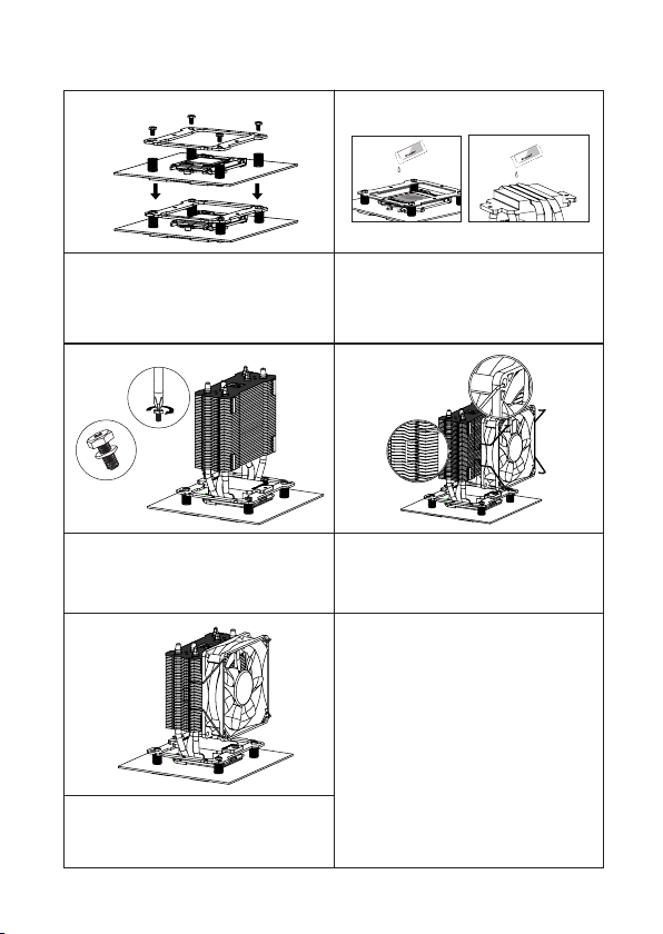
Step 5: Step 6:
4
1
2
3
2g
Chill Factor2gChill Factor
2g
Chill Factor2gChill Factor
Step 5 : Anchoring Mount Installation
Place the Anchoring Mount on the Screw
Nuts. Use the four M3L6 Screws to x the
Anchoring Mount on to the Screw Nuts.
Step 6 : Apply the Thermal Paste
Apply the Thermal Paste to the base of the heat-
sink and the surface of the CPU evenly. (A at
edge, like a business card or an old credit card
would be benecial in spreading the Thermal
Paste.)
Step 7: Step 8:
Step 7: Easy Access
Place the Heatsink Body on top of the CPU.
And then use the two M3L7 Screws to secure the
Anchoring Mount"
Step 8: Fan Installation
Place the included TY-9225B onto the Heatsink
Body. And then secure it with the Fan Clips, by
pulling the Fan Clips to place the four ends at the
four holes on the TY-9225B.
Step 9:
Step 9: Installation completed
Plug in the fan connector to the CPU PWM Fan
socket on the motherboard. Installation complete.
The Ultimate Cooling Solutions!
www.thermalright.com
4
Page 8
TRUE Spirit 90 Direct
AM2/AM2+/AM3/AM3+/AM4/FM1/FM2/FM2+
Exploded View
Important! Before proceeding with installation, please check for the most
up-to-date instructions at www.thermalright.com
Heatsink Body
Rubber Tubes
M3L7 Screw
M3L6 Screw
AMD Washer
(big)
5
Fan Clip
TY-9225B
Anchoring Mount
Screw Nut
Motherboard
Back Plate Cap
Mylar Film
Metal Back Plate
M3L10 Screw
Page 9
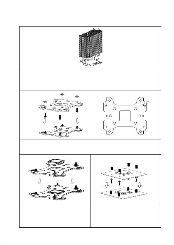
Installation Instructions:
Step 1:
Step1 : Rubber Tubes Installation
Insert the four black Rubber Tubes (Noise damping use) into the four indents on the front of the heatsink body. Do not remove them.
Step 2:
AM4
AM3
Step 2 : Backplate Installation
Choose the platform AMD AM3/AM4 you are in use. Make four M3L10 Screw Pillars go through the
Metal Back Plate and the Mylar lm from bottom towards top. And then place the Metal Back Plate on
the table. Put the four Washers (for AMD) around the Screw Pillars.
Step 3: Step 4:
Step 3 : Back Plate Cap
Note: When installing on an AMD platform, please
rst insert the Back Plate Cap into the opening on
the Metal Back plate, make sure you have the Cap
facing downwards.
Step 4 : Screw Cylinder Installation
Place the motherboard on top of the Back Plate.
See the four Screw Pillars go through the four
holes around the processor socket.Cap the four
Screw Pillars with the four Screw Nuts.Make sure
the side with a washer is facing the Back Plate.
The Ultimate Cooling Solutions!
www.thermalright.com
4
1
2
3
6
Page 10

Step 5: Step 6:
4
1
2
3
2g
Chill Factor2gChill Factor
2g
Chill Factor2gChill Factor
Step 5 : Anchoring Mount Installation
Place the Anchoring Mount on the Screw
Nuts. Use the four M3L6 Screws to x the
Anchoring Mount on to the Screw Nuts.
Step 6 : Apply the Thermal Paste
Apply the Thermal Paste to the base of the heat-
sink and the surface of the CPU evenly. (A at
edge, like a business card or an old credit card
would be benecial in spreading the Thermal
Paste.)
Step 7: Step 8:
Step 7: Easy Access
Place the Heatsink Body on top of the CPU.
And then use the two M3L7 Screws to secure the
Anchoring Mount"
Step 8: Fan Installation
Place the included TY-9225B onto the Heatsink
Body. And then secure it with the Fan Clips, by
pulling the Fan Clips to place the four ends at the
four holes on the TY-9225B.
Step 9:
Step 9: Installation completed
Plug in the fan connector to the CPU PWM Fan
socket on the motherboard. Installation complete.
Page 11

TRUE Spirit 90 Direct
Explosionszeichnung
Bitte prüfen Sie vor der Montage, ob für Ihren Kühler aktualisierte
Wichtig!
Montagehinweise auf der Webseite:
Intel 775/1150/1151/1155/1156/1366
www.thermalright.com
verfügbar sind.
Lüfterentkoppler
M3L7 Schraube
M3L6 Schraube
Montagerahmen
Backplateeinsatz
The Ultimate Cooling Solutions!
Kühlkörper
Lüfterklammer
TY-9225B
Rändelschraube
Motherboard
Intel Unterlegscheibe
(klein)
Leitschutzfolie
Multi Plattform Backplate
M3L10 Schraube
www.thermalright.com
8
Page 12

TRUE Spirit 90 Direct
Komponenten
1
2
4 5 76 8
9
13
TS-90 Direct
1
Kühlkörper ×1
Rändelschrauben ×4
4 5 6
M3 L6 Schraube ×5
7 8
Backplateeinsatz ×1
10
TY-9225B ×1
13
14
1110 12
Montagerahmen ×1
2
M3L7 Schraube ×3
Intel Unterlegscheibe
(klein) ×4
Lüfterklammer ×4
11
Schraubendreher ×1
14
15
3
9
12
15
3
Chill Factor
Mulit Plattform
Backplate ×1
M3L10 Schraube ×5
AMD Unterlegscheibe
(groß) ×4
Wärmeleitpaste ×1
Lüfterentkoppler ×8
2g
9
Page 13

Installationsanleitung:
Schritt 1:
Nehmen Sie den TS-90 Direct aus dem Karton. Bringen Sie die vier Lüfterentkoppler in den
vorgesehenen Vertiefungen auf der Vorderseite des Kühlkörpers an.
Schritt 2:
Achten Sie auf die entsprechenden Intel Sockel (775/1150/1151/1155/1156/1366) vorgesehene
Bohrungen in der Multi Plattform Backplate. Führen Sie die M3L10 Schrauben jeweils von unten durch
die Backplate und die mitgelieferte Leitschutzfolie und legen dann die Backplate auf den Tisch. Legen
Sie die vier Unterlegscheiben (für Intel) über die hervorstehenden Gewinde.
Schritt 3:
Schritt 4:
1
Beachten Sie:
Bei Verwendung einer Intel Socket 775 Plattform
setzen Sie zuerst den Backplateeinsatz in die
quadratische Öffnung der Backplate ein. Gehen
Sie sicher das der Aufsatz nach unten zeigt.
(Nur für LGA775 Plattformen)
The Ultimate Cooling Solutions!
Platzieren Sie das Mainboard von oben auf die
Backplate, so dass die hervorstehenden
Schraubgewinde durch die Löcher um den
Prozessorsockel gehen. Schrauben Sie die
vier beiliegenden Rändelschrauben auf die vier
Schraubengewinde. Achten Sie dabei darauf, dass
die Seite mit der Unterlegscheibe zur Backplate
zeigt.
www.thermalright.com
1150
1151
1366
1155
775
1156
4
2
3
10
Page 14

Schritt 5: Schritt 6:
4
1
2
3
2g
Chill Factor2gChill Factor
2g
Chill Factor2gChill Factor
Setzen Sie den Montagerahmen auf die vier
Rändelschrauben. Verwenden Sie die vier
M3L6 Schrauben, um den Montagerahmen
auf den Rändelschrauben zu befestigen.
Tragen Sie eine hauchdünne Schicht
Wärmeleitpaste auf der Oberäche der CPU und
auf der Unterseite des Kühlers auf.
Schritt 7: Schritt 8:
Platzieren Sie den Kühlkörper auf der CPU.
Nutzen Sie die zwei M3L7 Schrauben um den
Montagerahmen zu sichern.
Platzieren Sie den TY-9225B an dem Kühlkörper
und bringen Sie die Lüfterklammern an. Dazu
haken Sie die Lüfterklammern in die äußeren
Montagelöcher des Lüfters ein (s. Zeichnung)
und spannen sie sie in die dafür vorgesehenen
Aussparungen an den Seiten des Kühlkörpers ein.
Schritt 9:
Schließen Sie den Lüfterstecker an den CPU
PWM Lüfteranschluss auf dem Mainboard an
Die Installation ist abgeschlossen.
Page 15

TRUE Spirit 90 Direct
TRUE Spirit 90 Direct
Explosionszeichnung
Bitte prüfen Sie vor der Montage, ob für Ihren Kühler aktualisierte
Wichtig!
Montagehinweise auf der Webseite:
AM2/AM2+/AM3/AM3+/AM4/FM1/FM2/FM2+
www.thermalright.com
verfügbar sind.
Kühlkörper
Lüfterentkoppler
M3L7 Schraube
M3L6 Schraube
Montagerahmen
Backplateeinsatz
AMD Unterlegscheibe
(groß)
The Ultimate Cooling Solutions!
Lüfterklammer
TY-9225B
Rändelschraube
Motherboard
Leitschutzfolie
Multi Plattform Backplate
M3L10 Schraube
www.thermalright.com
12
Page 16

Installationsanleitung:
Schritt 1:
Nehmen Sie den TS-90 Direct aus dem Karton. Bringen Sie die vier Lüfterentkoppler in den
vorgesehenen Vertiefungen auf der Vorderseite des Kühlkörpers an.
Schritt 2:
Achten Sie auf die für den AMD AM3/AM4 Sockel vorgesehene Bohrungen in der Multi Plattform
Backplate. Führen Sie die vier M3L10 Schrauben jeweils von unten durch die Backplate und
die mitgelieferte Leitschutzfolie und legen dann die Backplate auf den Tisch. Legen Sie die vier
Unterlegscheiben (für AMD) über die hervorstehenden Gewinde.
Schritt 3:
Schritt 4:
4
1
2
3
AM4
AM3
Bei Verwendung einer AMD Sockel 939 Plattform
setzen Sie zuerst den Backplateeinsatz in die
quadratische Öffnung der Backplate ein. Gehen
Sie sicher, dass der Aufsatz nach unten zeigt.
13
Platzieren Sie das Mainboard von oben auf die
Backplate, so dass die hervorstehenden
Schraubgewinde durch die Löcher um den
Prozessorsockel gehen. Schrauben Sie die
vier beiliegenden Rändelschrauben auf die vier
Schraubengewinde. Achten Sie dabei darauf, dass
die Seite mit der Unterlegscheibe zur Backplate
zeigt.
Page 17

Schritt 5: Schritt 6:
4
1
2
3
2g
Chill Factor2gChill Factor
2g
Chill Factor2gChill Factor
Setzen Sie den Montagerahmen auf die
Rändelschrauben. Verwenden Sie die vier
M3L6 Schrauben, um den Montagerahmen
auf den Rändelschrauben zu befestigen
Tragen Sie eine hauchdünne Schicht
Wärmeleitpaste auf der Oberäche der CPU und
auf der Unterseite des Kühlers auf.
Schritt 7: Schritt 8:
Platzieren Sie den Kühlkörper auf der CPU.
Nutzen Sie die zwei M3L7 Schrauben um den
Montagerahmen zu sichern.
Platzieren Sie den TY-9225B an dem Kühlkörper
und bringen Sie die Lüfterklammern an. Dazu
haken Sie die Lüfterklammern in die äußeren
Montagelöcher des Lüfters ein (s. Zeichnung)
und spannen sie sie in die dafür vorgesehenen
Aussparungen an den Seiten des Kühlkörpers ein.
Schritt 9:
Schließen Sie den Lüfterstecker an den CPU
PWM Lüfteranschluss auf dem Mainboard an.
Die Installation ist abgeschlossen.
The Ultimate Cooling Solutions!
www.thermalright.com
14
Page 18

TRUE Spirit 90 Direct
爆炸圖
注意 ! 在您安裝前請先至官網首頁查看是否有更新版安裝指南
www.thermalright.com
Intel 775/1150/1151/1155/1156/1366
M3L7
M3L6
螺絲
多孔扣具
Intel 墊片( 小 )
775/AMD 背蓋
15
散熱器本體
橡膠管
螺絲
手轉螺絲
主機板
鐵背板
M3L10
風扇線扣
TY-9225B
塑膠絕緣片
螺絲
Page 19

分裝圖
1
2
4 5 76 8
9
13
TS-90 Direct
1
散熱器本體
手轉螺絲
4 5 6
M3 L6
螺絲
7 8
775/AMD 背蓋
10
TY-9225B ×1
13
14
×1
×4
×5
×1
1110 12
×1
多孔扣具
2
螺絲
Intel 墊片 ( 小 )
風扇線扣
11
塑膠絕緣片
14
15
3
×3
×4
9
×4
×1
12
15
3
Chill Factor
×1
鐵背板
M3L10
螺絲
AMD 墊片 ( 大 )
×1
導熱膏
×8
橡膠管
2g
×5M3L7
×4
The Ultimate Cooling Solutions!
www.thermalright.com
16
Page 20

安裝指南 :
步驟一 :
步驟一 :
將四個黑色矽膠管放入鰭片的四個凹痕
步驟二 :
1150
1151
1366
1155
775
1156
步驟二 :
依照您的處理器類型 (
穿過鐵背板及塑膠絕緣片後套上 Intel 墊圈 ( 小 )。
775/1150/1151/1155/1156/1366
步驟三 :
步驟三 :
注意 ! 當您安裝於 775 主機板時,請先將775 背
蓋安裝於鐵背板上。
17
) 選擇對應於鐵背板的孔位,將四根 M3L10 螺絲
步驟四 :
步驟四 :
將鐵背板安裝於主機板背面,再依序將穿過主機
板的四個螺絲套上手轉螺絲。
4
1
2
3
Page 21

步驟五 : 步驟六 :
4
1
2
3
2g
Chill Factor2gChill Factor
2g
Chill Factor2gChill Factor
步驟五 :
將多孔扣具置於手轉螺絲上,再將 M3L6螺
絲穿過多孔扣具,依序鎖入手轉螺絲上。
步驟六 :
塗抹導熱膏於散熱器熱導管及中央處理器銅蓋
上。
步驟七 : 步驟八 :
步驟七
將散熱器置放於中央處理器上,再用 M3L7 螺絲
穿過散熱器底部兩邊的螺絲孔位,鎖入多孔扣具
的對應孔位。
步驟八 :
將風扇平貼於散熱器上,並將風扇線扣扣置風扇
螺絲固定孔。
步驟九 :
步驟九 :
最後將風扇接頭插入主機板上的 CPU FAN 插
槽,安裝完成。
The Ultimate Cooling Solutions!
www.thermalright.com
18
Page 22

TRUE Spirit 90 Direct
爆炸圖
注意 ! 在您安裝前請先至官網首頁查看是否有更新版安裝指南
www.thermalright.com
AM2/AM2+/AM3/AM3+/AM4/FM1/FM2/FM2+
橡膠管
M3L7
M3L6
螺絲
多孔扣具
AMD 墊片 ( 大 )
塑膠絕緣片
19
散熱器本體
螺絲
手轉螺絲
主機板
775/AMD 背蓋
鐵背板
M3L10
螺絲
風扇線扣
TY-9225B
Page 23

安裝指南 :
步驟一 :
步驟一 :
將四個黑色矽膠管放入鰭片的四個凹痕
步驟二 :
步驟二 :
依照您的處理器類型選擇對應於鐵背板的孔位,將四根 M3L10螺絲穿過鐵背板及塑膠絕緣片後套上
AMD 墊圈 ( 大 )。
AM4
AM3
步驟三 :
步驟三 :
注意 ! 當您安裝於 939 主機板時,請先將 939背
蓋安裝於鐵背板上。
步驟四 :
步驟四 :
將鐵背板安裝於主機板背面,再依序將穿過主機
板的四個螺絲套上手轉螺絲。
The Ultimate Cooling Solutions!
4
1
2
3
www.thermalright.com
20
Page 24

TRUE Spirit 90 Direct
步驟五
步驟五 :
將多孔扣具置於手轉螺絲上,再將 M3L6螺
絲穿過多孔扣具,依序鎖入手轉螺絲上。
4
1
2
3
步驟七 :
步驟七 :
將散熱器置放於中央處理器上,再用 M3L7 螺絲
穿過散熱器底部兩邊的螺絲孔位,鎖入多孔扣具
的對應孔位。
步驟九 :
步驟六 :
2g
Chill Factor2gChill Factor
步驟六 :
塗抹導熱膏於散熱器熱導管及中央處理器銅蓋上。
2g
Chill Factor2gChill Factor
步驟八 :
步驟八 :
將風扇平貼於散熱器上,並將風扇線扣扣置風扇
螺絲固定孔。
步驟九 :
最後將風扇接頭插入主機板上的 CPU FAN插槽,
安裝完成。
21
Page 25

TRUE Spirit 90 Direct
Technical Spec
Heatsink Specifications:
Dimension: Length 104mm x Width 77mm x Height 122mm
Weight: 250g
Heatpipe: 6mm heatpipe*3 units
Fan Specification:
Dimension: L92mm x H92mm x W25mm
Weight: 100g
Fan speed: 800~2000RPM
Fan noise: 21~27dBA MAX
Airflow: 15.75~39.36CFM MAX
Connector: 4 Pin (PWM Fan connector)
The Ultimate Cooling Solutions!
www.thermalright.com
22
Page 26

TRUE Spirit 90 Direct
Technische Spezikationen
Kühlkörper Spezifikationen:
Maße: Länge 104mm x Breite 77mm x Höhe 122mm
Gewicht: 250g
Heatpipe: 6mm Heatpipe*3 Stück
Lüfter Spezifikationen:
Maße: L92mm x H92mm x B25mm
Gewicht: 100g
Drehzahl: 800~2000 U/min
Lautstärke: 21~27dBA max.
Fördermenge: 15.75~39.36CFM MAX
Anschluss: 4 Pin (PWM Lüfteranschluss)
23
Page 27

TRUE Spirit 90 Direct
散熱器規格書
散熱器規格 :
尺寸 : 長 104mm x 寬 77mm x 高 122mm
重量 : 250 克
熱導管 : 6mm 熱導管 *3 支
風扇規格 :
尺寸 : 長 92mm x 高 92mm x 寬 25mm
重量 : 100 克
風扇轉速 : 800~2000RPM
風扇噪音 : 21~27dBA MAX
風量 : 15.75~39.36CFM MAX
接頭類型 : 4Pin PWM 接頭
The Ultimate Cooling Solutions!
www.thermalright.com
24
Page 28

TRUE Spirit 90 Direct
104
42
77
122.35
35.95
25
32
40
32
40
Page 29

Page 30

The Ultimate Cooling Solutions!
Thermalright Produkte werden in
Europa importiert und vertrieben
durch die:
PC-Cooling GmbH
Eichenallee 3
24589 Nortorf
www.thermalright.com
TEL: +886-2-2915-5005
FAX: +886-2-2915-5123
EMAIL: sales@thermalright.com
170612
 Loading...